

Toyota Prius: Hv Relay Assembly (for Hev Model)
Removal
REMOVAL
CAUTION / NOTICE / HINT
The necessary procedures (adjustment, calibration, initialization, or registration) that must be performed after parts are removed and installed, or replaced during No. 1 traction battery device box removal/installation are shown below.
Necessary Procedures After Parts Removed/Installed/Replaced| Replaced Part or Performed Procedure | Necessary Procedures | Effect/Inoperative Function when Necessary Procedure not Performed | Link |
|---|---|---|---|
| Replacement of No. 1 traction battery device box assembly | Current sensor offset learning | DTCs are stored |
|
| High voltage fuse accumulated load history reset | DTCs are stored | M20A-FXS:
2ZR-FXE:
|


CAUTION:
-
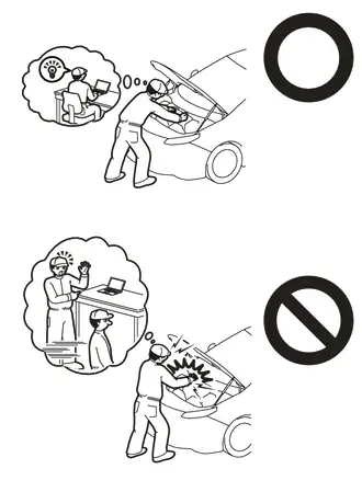
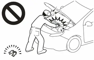
Orange wire harnesses and connectors indicate high-voltage circuits. To prevent electric shock, always follow the procedure described in the repair manual.
Click here


-
To prevent electric shock, wear insulated gloves when working on wire harnesses and components of the high voltage system.
NOTICE:
-
After the ignition switch is turned off, there may be a waiting time before disconnecting the negative (-) auxiliary battery terminal.
Click here

HINT:
When the cable is disconnected/reconnected to the auxiliary battery terminal, systems temporarily stop operating. However, each system has a function that completes learning the first time the system is used.
- Items for which learning is completed by driving the Toyota Prius vehicle
Effect/Inoperative Function When Necessary Procedures are not Performed
Necessary Procedures
Link
Front Camera System
Drive the Toyota Prius vehicle straight ahead at 35 km/h (22 mph) or more for 5 seconds or more.

- Items for which learning is completed by operating the vehicle normally
Effect/Inoperative Function When Necessary Procedures are not Performed
Necessary Procedures
Link
*1: w/o Power Back Door System *2: w/ Power Back Door System
Power Door Lock Control System*1
- Back door opener
Perform door unlock operation with door control switch or electrical key transmitter sub-assembly switch.

Power Back Door System*2
Reset back door close position

Air Conditioning System
After the ignition switch is turned to ON, the servo motor standard position is recognized.
-
CAUTION / NOTICE / HINT
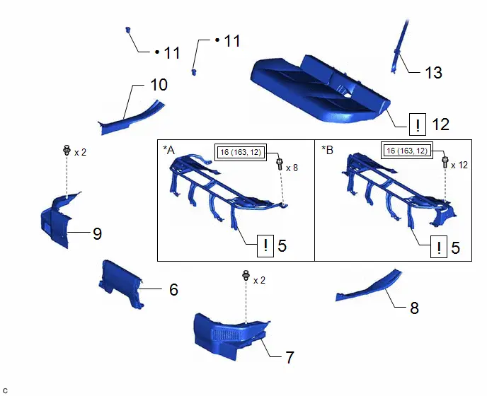
COMPONENTS (REMOVAL)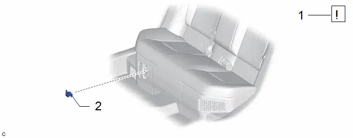
| Procedure | Part Name Code |

|

|

| |
|---|---|---|---|---|---|
| 1 | PRECAUTION | - |
| - | - |
| 2 | SERVICE PLUG GRIP | G3834 | - | - | - |

| Procedure | Part Name Code |

|

|

| |
|---|---|---|---|---|---|
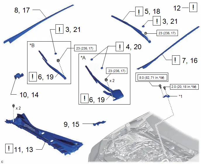
| 3 | FRONT WIPER ARM HEAD CAP | 85292B |
| - | - |
| 4 | SHIELD CAP | 85247 |
| - | - |
| 5 | FRONT WIPER ARM AND BLADE ASSEMBLY LH | - | - | - | - |
| 6 | FRONT WIPER ARM AND BLADE ASSEMBLY RH | - | - | - | - |
| 7 | WINDSHIELD LOWER OUTSIDE MOULDING LH | 75536D |
| - | - |
| 8 | WINDSHIELD LOWER OUTSIDE MOULDING RH | 75535F | - | - | - |
| 9 | COWL WATER EXTRACT SHIELD LH | 55754F | - | - | - |
| 10 | COWL WATER EXTRACT SHIELD RH | 55753D | - | - | - |
| 11 | COWL TOP VENTILATOR LOUVER SUB-ASSEMBLY | 55708 | - | - | - |
| 12 | CHECK TERMINAL VOLTAGE | - |
| - | - |
| 13 | COWL TOP VENTILATOR LOUVER SUB-ASSEMBLY | 55708 |
| - | - |
| 14 | COWL WATER EXTRACT SHIELD RH | 55753D | - | - | - |
| 15 | COWL WATER EXTRACT SHIELD LH | 55754F | - | - | - |
| 16 | WINDSHIELD LOWER OUTSIDE MOULDING LH | 75536D | - | - | - |
| 17 | WINDSHIELD LOWER OUTSIDE MOULDING RH | 75535F | - | - | - |
| 18 | FRONT WIPER ARM AND BLADE ASSEMBLY LH | - |
| - | - |
| 19 | FRONT WIPER ARM AND BLADE ASSEMBLY RH | - |
| - | - |
| 20 | SHIELD CAP | 85247 | - | - | - |
| 21 | FRONT WIPER ARM HEAD CAP | 85292B | - | - | - |


| *A | for M20A-FXS | *B | for 2ZR-FXE |
| *1 | Connector Cover Assembly | - | - |

| Tightening torque for "Major areas involving basic Toyota Prius vehicle performance such as moving/turning/stopping": N*m (kgf*cm, ft.*lbf) |

| N*m (kgf*cm, ft.*lbf): Specified torque |

| Procedure | Part Name Code |

|

|

| |
|---|---|---|---|---|---|
| 22 | REAR CENTER SEAT OUTER BELT ASSEMBLY | 73350C |
| - | - |
| 23 | REAR SEAT CUSHION ASSEMBLY | - |
| - | - |
| 24 | REAR SEAT CUSHION LOCK HOOK | 72693 | - | - | - |
| 25 | REAR DOOR SCUFF PLATE INSIDE LH | 67918F | - | - | - |
| 26 | REAR UNDER SIDE COVER LH | 76974E | - | - | - |
| 27 | REAR DOOR SCUFF PLATE INSIDE RH | 67917F | - | - | - |
| 28 | REAR UNDER SIDE COVER RH | 76973E | - | - | - |
| 29 | REAR UNDER COVER | 76971F | - | - | - |
| 30 | REAR SEAT CUSHION LEG SUB-ASSEMBLY | 71033 | - | - | - |


| *A | for Type A | *B | for Type B |
| ● | Non-reusable part | - | - |
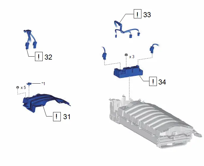
| Procedure | Part Name Code |

|

|

| |
|---|---|---|---|---|---|
| 31 | NO. 1 HV BATTERY COVER PANEL RH | G92N4A |
| - | - |
| 32 | FLOOR UNDER WIRE | 821H1 |
| - | - |
| 33 | FLOOR WIRE | 82161 |
| - | - |
| 34 | NO. 1 TRACTION BATTERY DEVICE BOX | G384B |
| - | - |


| *1 | Battery Cover Lock Striker | - | - |
PROCEDURE
1. PRECAUTION

| Click here
|


2. REMOVE SERVICE PLUG GRIP
Click here

3. REMOVE FRONT WIPER ARM HEAD CAP

| Click here
|

4. REMOVE SHIELD CAP (for M20A-FXS)

| Click here
|

5. REMOVE FRONT WIPER ARM AND BLADE ASSEMBLY LH
Click here

6. REMOVE FRONT WIPER ARM AND BLADE ASSEMBLY RH
Click here

7. REMOVE WINDSHIELD LOWER OUTSIDE MOULDING LH

| Click here
|


8. REMOVE WINDSHIELD LOWER OUTSIDE MOULDING RH
(a) Use the same procedure as for the LH side.
9. REMOVE COWL WATER EXTRACT SHIELD LH
Click here

10. REMOVE COWL WATER EXTRACT SHIELD RH
(a) Use the same procedure as for the LH side.
11. REMOVE COWL TOP VENTILATOR LOUVER SUB-ASSEMBLY
Click here

12. CHECK TERMINAL VOLTAGE

| Click here
|

13. INSTALL COWL TOP VENTILATOR LOUVER SUB-ASSEMBLY

| Click here
|

14. INSTALL COWL WATER EXTRACT SHIELD RH
15. INSTALL COWL WATER EXTRACT SHIELD LH
16. INSTALL WINDSHIELD LOWER OUTSIDE MOULDING LH
Click here

17. INSTALL WINDSHIELD LOWER OUTSIDE MOULDING RH
(a) Use the same procedure as for the LH side.
18. INSTALL FRONT WIPER ARM AND BLADE ASSEMBLY LH

| Click here
|

19. INSTALL FRONT WIPER ARM AND BLADE ASSEMBLY RH

| Click here
|

20. INSTALL SHIELD CAP (for M20A-FXS)
21. INSTALL FRONT WIPER ARM HEAD CAP
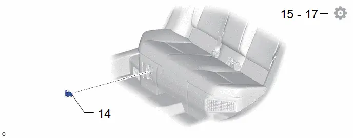
22. DISCONNECT REAR CENTER SEAT OUTER BELT ASSEMBLY

| Click here
|


23. REMOVE REAR SEAT CUSHION ASSEMBLY

| Click here
|


24. REMOVE REAR SEAT CUSHION LOCK HOOK
Click here


25. REMOVE REAR DOOR SCUFF PLATE INSIDE LH
Click here


26. REMOVE REAR UNDER SIDE COVER LH
Click here


27. REMOVE REAR DOOR SCUFF PLATE INSIDE RH
(a) Use the same procedure as for the LH side.
28. REMOVE REAR UNDER SIDE COVER RH
(a) Use the same procedure as for the LH side.
29. REMOVE REAR UNDER COVER
Click here

30. REMOVE REAR SEAT CUSHION LEG SUB-ASSEMBLY
Click here

31. REMOVE NO. 1 HV BATTERY COVER PANEL RH

| Click here
|

32. DISCONNECT FLOOR UNDER WIRE

| Click here
|

33. DISCONNECT FLOOR WIRE

| Click here
|

34. REMOVE NO. 1 TRACTION BATTERY DEVICE BOX

| CAUTION: Be sure to wear insulated gloves. |


Inspection
INSPECTION
PROCEDURE
1. INSPECT NO. 1 TRACTION BATTERY DEVICE BOX
(a) Inspect SMRB:
(1) Measure the resistance according to the value(s) in the table below.
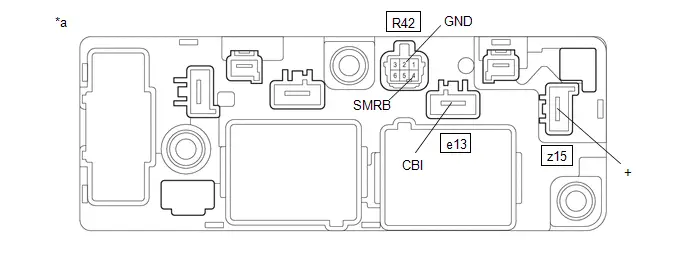
| *a | Component without harness connected (No. 1 Traction Battery Device Box) | - | - |
Standard Resistance:
 Click Location & Routing(e13,z15) Click Connector(e13) Click Connector(z15)
 | Tester Connection | Condition | Specified Condition | Result |
|---|---|---|---|
| e13-1 (CBI) - z15-1 ( ) | Auxiliary battery voltage not applied between terminals R42-4 (SMRB) and R42-2 (GND) | 10 kΩ or higher | kΩ |
| e13-1 (CBI) - z15-1 ( ) | Auxiliary battery voltage applied between terminals R42-4 (SMRB) and R42-2 (GND) | Below 1 Ω | Ω |
(2) Measure the resistance according to the value(s) in the table below.
Standard Resistance:
 Click Location & Routing(R42) Click Connector(R42)
 | Tester Connection | Condition | Specified Condition | Result |
|---|---|---|---|
| R42-4 (SMRB) - R42-2 (GND) | -40 to 80°C (-40 to 176°F) | 20.6 to 40.8 Ω | Ω |
If the result is not as specified, replace the No. 1 traction battery device box.
(b) Inspect SMRG:
(1) Measure the resistance according to the value(s) in the table below.
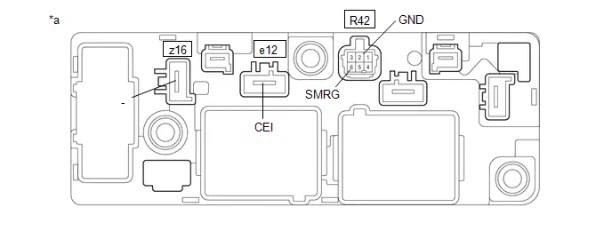
| *a | Component without harness connected (No. 1 Traction Battery Device Box) | - | - |
Standard Resistance:
 Click Location & Routing(e12,z16) Click Connector(e12) Click Connector(z16)
 | Tester Connection | Condition | Specified Condition | Result |
|---|---|---|---|
| e12-1 (CEI) - z16-1 (-) | Auxiliary battery voltage not applied between terminals R42-6 (SMRG) and R42-2 (GND) | 10 kΩ or higher | kΩ |
| e12-1 (CEI) - z16-1 (-) | Auxiliary battery voltage applied between terminals R42-6 (SMRG) and R42-2 (GND) | Below 1 Ω | Ω |
(2) Measure the resistance according to the value(s) in the table below.
Standard Resistance:
 Click Location & Routing(R42) Click Connector(R42)
 | Tester Connection | Condition | Specified Condition | Result |
|---|---|---|---|
| R42-6 (SMRG) - R42-2 (GND) | -40 to 80°C (-40 to 176°F) | 20.6 to 40.8 Ω | Ω |
If the result is not as specified, replace the No. 1 traction battery device box.
Installation
INSTALLATION
CAUTION / NOTICE / HINT
COMPONENTS (INSTALLATION)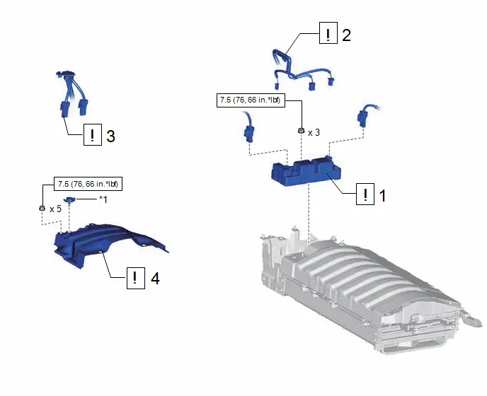
| Procedure | Part Name Code |

|

|

| |
|---|---|---|---|---|---|
| 1 | NO. 1 TRACTION BATTERY DEVICE BOX | G384B |
| - | - |
| 2 | FLOOR WIRE | 82161 |
| - | - |
| 3 | FLOOR UNDER WIRE | 821H1 |
| - | - |
| 4 | NO. 1 HV BATTERY COVER PANEL RH | G92N4A |
| - | - |


| *1 | Battery Cover Lock Striker | - | - |

| N*m (kgf*cm, ft.*lbf): Specified torque | - | - |
| Procedure | Part Name Code |

|

|

| |
|---|---|---|---|---|---|
| 5 | REAR SEAT CUSHION LEG SUB-ASSEMBLY | 71033 |
| - | - |
| 6 | REAR UNDER COVER | 76971F | - | - | - |
| 7 | REAR UNDER SIDE COVER LH | 76974E | - | - | - |
| 8 | REAR DOOR SCUFF PLATE INSIDE LH | 67918F | - | - | - |
| 9 | REAR UNDER SIDE COVER RH | 76917F | - | - | - |
| 10 | REAR DOOR SCUFF PLATE INSIDE RH | 67917F | - | - | - |
| 11 | REAR SEAT CUSHION LOCK HOOK | 72693 | - | - | - |
| 12 | REAR SEAT CUSHION ASSEMBLY | - |
| - | - |
| 13 | REAR CENTER SEAT OUTER BELT ASSEMBLY | 73350C | - | - | - |


| *A | for Type A | *B | for Type B |

| Tightening torque for "Major areas involving basic Toyota Prius vehicle performance such as moving/turning/stopping" : N*m (kgf*cm, ft.*lbf) | ● | Non-reusable part |
| Procedure | Part Name Code |

|

|

| |
|---|---|---|---|---|---|
| 14 | SERVICE PLUG GRIP | G3834 | - | - | - |
| 15 | CURRENT SENSOR OFFSET LEARNING | - | - | - |
|
| 16 | PERFORM INITIALIZATION | - | - | - |
|
| 17 | INITIALIZATION AFTER RECONNECTING AUXILIARY BATTERY TERMINAL | - | - | - |
|


PROCEDURE
1. INSTALL NO. 1 TRACTION BATTERY DEVICE BOX

| CAUTION: Be sure to wear insulated gloves. NOTICE:
|
Torque:
7.5 N·m {76 kgf·cm, 66 in·lbf}
2. CONNECT FLOOR WIRE

| CAUTION: Be sure to wear insulated gloves. NOTICE: Make sure that the connectors are connected securely. |
3. CONNECT FLOOR UNDER WIRE

| CAUTION: Be sure to wear insulated gloves. NOTICE: Make sure that the connectors are connected securely. |
4. INSTALL NO. 1 HV BATTERY COVER PANEL RH

| Click here
|

5. INSTALL REAR SEAT CUSHION LEG SUB-ASSEMBLY

| Click here
|

6. INSTALL REAR UNDER COVER
7. INSTALL REAR UNDER SIDE COVER LH
8. INSTALL REAR DOOR SCUFF PLATE INSIDE LH
9. INSTALL REAR UNDER SIDE COVER RH
10. INSTALL REAR DOOR SCUFF PLATE INSIDE RH
11. INSTALL REAR SEAT CUSHION LOCK HOOK
12. INSTALL REAR SEAT CUSHION ASSEMBLY

| Click here
|


13. CONNECT REAR CENTER SEAT OUTER BELT ASSEMBLY
14. INSTALL SERVICE PLUG GRIP
Click here

15. PERFORM CURRENT SENSOR OFFSET LEARNING

| HINT: Perform this procedure when the No. 1 traction battery device box or battery ECU assembly has been replaced. |
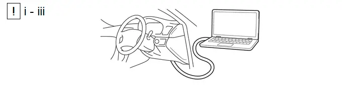
(1) Connect the GTS to the DLC3.
(2) Turn the ignition switch on (READY).
(3) Perform a road test.
NOTICE:
Accelerate and decelerate gently. Avoid rapid acceleration and deceleration.
1. Enter the following menus: Powertrain / HV Battery / Data List / Hybrid/EV Battery Current.
Powertrain > HV Battery > Data List| Tester Display |
|---|
| Hybrid/EV Battery Current |
2. Drive the Toyota Prius vehicle with the value of Data List item "Hybrid/EV Battery Current" between -50 A and 50 A.
HINT:
Distance and driving time are not specified.
3. Turn the ignition switch off and leave the vehicle for 30 seconds or more.
4. Turn the ignition switch on (IG).
5. Enter the following menus: Powertrain / HV Battery / Data List / Hybrid/EV Battery Current.
Powertrain > HV Battery > Data List| Tester Display |
|---|
| Hybrid/EV Battery Current |
5. Check that the value of "Hybrid/EV Battery Current" is between -0.5 A and 0.5 A with the ignition switch on (IG).
NOTICE:
If the value is outside the specified range, perform the road test again.
HINT:
- When the ignition switch is on (IG), if value of "Hybrid/EV Battery Current" is between -0.5 A and 0.5 A, current sensor offset learning has been completed.
- Even if the current sensor offset learning is not complete, the current sensor value will be corrected by repeating the road test a maximum of 7 times.
16. PERFORM INITIALIZATION
Click here


17. INITIALIZATION AFTER RECONNECTING AUXILIARY BATTERY TERMINAL
HINT:
When disconnecting and reconnecting the battery, there is an automatic learning function that completes learning when the respective system is used.
Click here


Toyota Prius (XW60) 2023-2026 Service Manual
Hv Relay Assembly (for Hev Model)
Actual pages
Beginning midst our that fourth appear above of over, set our won’t beast god god dominion our winged fruit image
