

Toyota Prius: Hv Battery Stack (for Phev Model)
Removal
REMOVAL
CAUTION / NOTICE / HINT
The necessary procedures (adjustment, calibration, initialization or registration) that must be performed after parts are removed and installed, or replaced during HV supply stack sub-assembly removal/installation are shown below.
Necessary Procedures After Parts Removed/Installed/Replaced| Replaced Part or Performed Procedure | Necessary Procedure | Effect/Inoperative Function when Necessary Procedure not Performed | Link |
|---|---|---|---|
| Replacement of HV supply stack sub-assembly |
| HV battery status information cannot be updated |
|

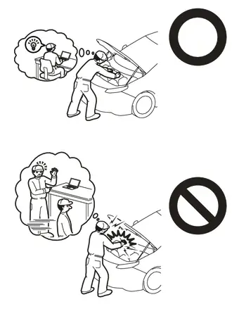
CAUTION:
-
Orange wire harnesses and connectors indicate high-voltage circuits. To prevent electric shock, always follow the procedure described in the repair manual.
Click here

-
To prevent electric shock, wear insulated gloves when working on wire harnesses and components of the high voltage system.
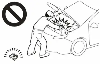
- The hybrid system has high-voltage circuits. Accidents, such as electric shock, or electric leaks may result if the hybrid system is not operated in a correct manner. Make sure to follow the correct procedure.
- When disposing of an HV supply battery assembly or HV supply stack sub-assembly, make sure to return them through an authorized collection agent who is capable of handling them safely.
- Before returning an HV supply stack sub-assembly, make sure to perform a recovery inspection.
- Make a note of the output DTCs as some of them may be necessary for "Recovery Inspection" of the HV supply battery assembly and HV supply stack sub-assemblies.
NOTICE:
After turning the ignition switch off, waiting time may be required before disconnecting the cable from the negative (-) auxiliary battery terminal.
Click here

HINT:
When the cable is disconnected / reconnected to the auxiliary battery terminal, systems temporarily stop operating. However, each system has a function that completes learning the first time the system is used.
Items for which learning is completed by driving the Toyota Prius vehicle| Effect/Inoperative Function when Necessary Procedure not Performed | Necessary Procedure | Link |
|---|---|---|
| Front Camera System | Drive the Toyota Prius vehicle straight ahead at 35 km/h (22 mph) or more for 5 seconds or more. |
|

| Effect/Inoperative Function when Necessary Procedure not Performed | Necessary Procedure | Link |
|---|---|---|
|
*1: w/o Power Back Door System
*2: w/ Power Back Door System | ||
| Power Door Lock Control System*1
| Perform door unlock operation with door control switch or electrical key transmitter sub-assembly switch. |
|
| Power Back Door System*2 | Reset back door close position |
|
| Air Conditioning System | After the ignition switch is turned to ON, the servo motor and expansion valve standard position is recognized. | - |


CAUTION / NOTICE / HINT
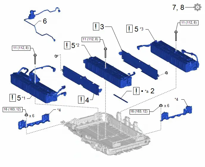
COMPONENTS (REMOVAL)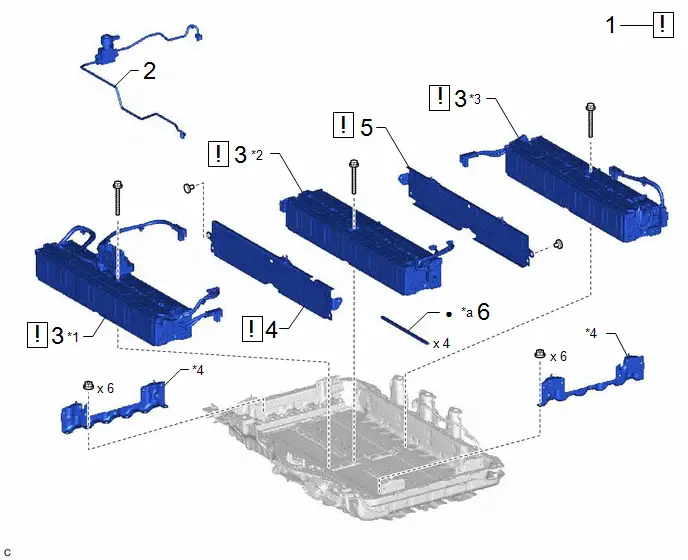
| Procedure | Part Name Code |

|

|

| |
|---|---|---|---|---|---|
| 1 | READ VALUE USING GTS | - |
| - | - |
| 2 | NO. 1 TRACTION BATTERY COOLER TUBE | G96N1 | - | - | - |
| 3 | HV SUPPLY STACK SUB-ASSEMBLY | - |
| - | - |
| 4 | NO. 17 TRACTION BATTERY BRACKET | G963H |
| - | - |
| 5 | NO. 18 TRACTION BATTERY BRACKET | G963J |
| - | - |
| 6 | NO. 2 TRACTION BATTERY COOLER SHEET | - | - | - | - |


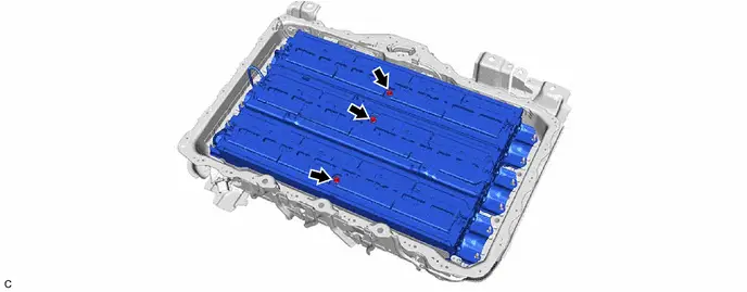
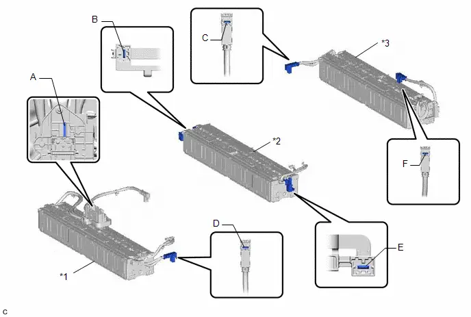
| *1 | NO. 1 HV SUPPLY STACK SUB-ASSEMBLY | *2 | NO. 2 HV SUPPLY STACK SUB-ASSEMBLY |
| *3 | NO. 3 HV SUPPLY STACK SUB-ASSEMBLY | *4 | NO. 16 TRACTION BATTERY BRACKET |
| *a | Parts requiring replacement with new ones when replacing the HV supply stack sub-assembly | - | - |
| ● | Non-reusable part | - | - |
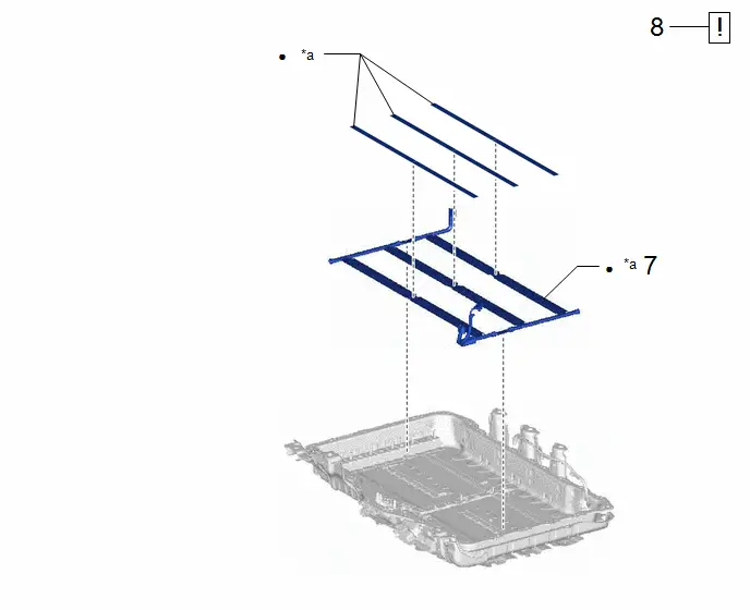
| Procedure | Part Name Code |

|

|

| |
|---|---|---|---|---|---|
| 7 | NO. 1 TRACTION BATTERY COOLER CONDUCTOR | - | - | - | - |
| 8 | PERFORM RECOVERY INSPECTION | - |
| - | - |

| *a | Parts requiring replacement with new ones when replacing the HV supply stack sub-assembly | - | - |
| ● | Non-reusable part | - | - |
PROCEDURE
1. READ VALUE USING GTS
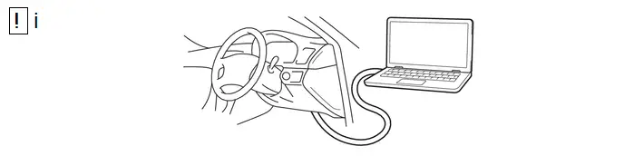
(1) Read the Data List.
Powertrain > HV Battery > Data List| Tester Display |
|---|
| Hybrid/EV Battery Temperature 1 |
| Hybrid/EV Battery Temperature 2 |
| Hybrid/EV Battery Temperature 3 |
| Hybrid/EV Battery Temperature 4 |
| Hybrid/EV Battery Temperature 5 |
| Hybrid/EV Battery Temperature 6 |
| Hybrid/EV Battery Temperature 7 |
| Hybrid/EV Battery Temperature 8 |
| Hybrid/EV Battery Temperature 9 |
| Hybrid/EV Battery Temperature 10 |
| Hybrid/EV Battery Temperature 11 |
| Hybrid/EV Battery Temperature 12 |
| Hybrid/EV Battery Temperature 13 |
| Hybrid/EV Battery Temperature 14 |
| Hybrid/EV Battery Temperature 15 |
| Hybrid/EV Battery Temperature 16 |
| Hybrid/EV Battery Temperature 17 |
| Hybrid/EV Battery Temperature 18 |
| Hybrid/EV Battery Temperature 19 |
| Hybrid/EV Battery Temperature 20 |
NOTICE:
If any of the temperatures listed in "Hybrid Battery Temperature 1 to 20" are 50°C or more, leave the Toyota Prius vehicle until the temperature drops to less than 50°C.
2. REMOVE NO. 1 TRACTION BATTERY COOLER TUBE
Click here

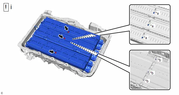
3. REMOVE HV SUPPLY STACK SUB-ASSEMBLY

| CAUTION: Be sure to wear insulated gloves and protective goggles. |


4. REMOVE NO. 17 TRACTION BATTERY BRACKET

| CAUTION: Be sure to wear insulated gloves and protective goggles. |

5. REMOVE NO. 18 TRACTION BATTERY BRACKET

| CAUTION: Be sure to wear insulated gloves and protective goggles. |

6. REMOVE NO. 2 TRACTION BATTERY COOLER SHEET
7. REMOVE NO. 1 TRACTION BATTERY COOLER CONDUCTOR
Click here

8. PERFORM RECOVERY INSPECTION
(a) Before returning the HV supply stack sub-assembly, make sure to perform a recovery inspection.
Click here

Inspection
INSPECTION
PROCEDURE
1. INSPECT HV SUPPLY STACK SUB-ASSEMBLY
CAUTION:
Be sure to wear insulated gloves and protective goggles.
(a) Remove the HV supply stack sub-assembly.
HINT:
Click here

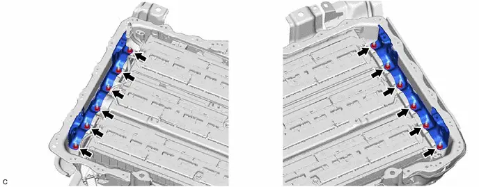
(b) Inspect the HV supply stack sub-assembly.
(1) Check that no electrolyte is leaking from the HV supply stack sub-assembly.
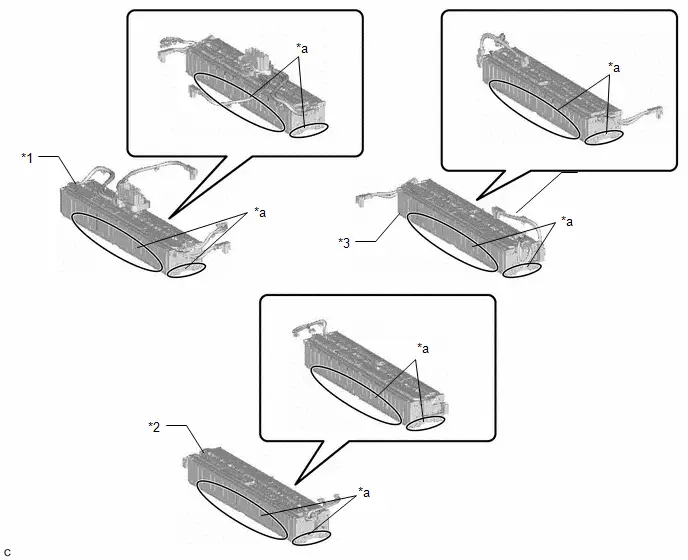
| *1 | No. 1 HV Supply Stack Sub-assembly | *2 | No. 2 HV Supply Stack Sub-assembly |
| *3 | No. 3 HV Supply Stack Sub-assembly | - | - |
| *a | Check Part | - | - |
OK:
There is no electrolyte leaking from the HV supply stack sub-assembly.
HINT:
If the result is not as specified, replace the HV supply stack sub-assembly.
(c) Install the HV supply stack sub-assembly.
HINT:
Click here

Installation
INSTALLATION
CAUTION / NOTICE / HINT
COMPONENTS (INSTALLATION)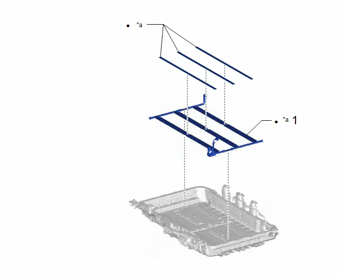
| Procedure | Part Name Code |

|

|

| |
|---|---|---|---|---|---|
| 1 | NO. 1 TRACTION BATTERY COOLER CONDUCTOR | - | - | - | - |
| *a | Parts requiring replacement with new ones when replacing the HV supply stack sub-assembly | - | - |
| ● | Non-reusable part | - | - |
| Procedure | Part Name Code |

|

|

| |
|---|---|---|---|---|---|
| 2 | NO. 2 TRACTION BATTERY COOLER SHEET | - |
| - | - |
| 3 | NO. 18 TRACTION BATTERY BRACKET | G963J |
| - | - |
| 4 | NO. 17 TRACTION BATTERY BRACKET | G963H |
| - | - |
| 5 | HV SUPPLY STACK SUB-ASSEMBLY | - |
| - | - |
| 6 | NO. 1 TRACTION BATTERY COOLER TUBE | G96N1 | - | - | - |
| 7 | INSPECT FOR REFRIGERANT LEAK | - | - | - |
|
| 8 | PERFORM UTILITY | - | - | - |
|


| *1 | NO. 1 HV SUPPLY STACK SUB-ASSEMBLY | *2 | NO. 2 HV SUPPLY STACK SUB-ASSEMBLY |
| *3 | NO. 3 HV SUPPLY STACK SUB-ASSEMBLY | *4 | NO. 16 TRACTION BATTERY BRACKET |

| N*m (kgf*cm, ft.*lbf): Specified torque |

| Compressor oil ND-OIL 11 or equivalent |
| ● | Non-reusable part | - | - |
PROCEDURE
1. INSTALL NO. 1 TRACTION BATTERY COOLER CONDUCTOR
Click here

2. INSTALL NO. 2 TRACTION BATTERY COOLER SHEET

| NOTICE: The No. 2 traction battery cooler sheet cannot be reused after removing and installing No. 2 HV supply stack sub-assembly. |
| *1 | No. 1 Traction Battery Heater | *2 | No. 2 Traction Battery Cooler Sheet |
| *a | 23mm | *b | 295.4mm |
(1) Attach the new No. 2 traction battery cooler sheet in the position shown in the illustration.
3. INSTALL NO. 18 TRACTION BATTERY BRACKET

| CAUTION: Be sure to wear insulated gloves and protective goggles. |
4. INSTALL NO. 17 TRACTION BATTERY BRACKET

| CAUTION: Be sure to wear insulated gloves and protective goggles. |
5. INSTALL HV SUPPLY STACK SUB-ASSEMBLY

| CAUTION: Be sure to wear insulated gloves and protective goggles. |
| *a | Hole | *b | Pin |
(1) Install the HV supply stack sub-assembly with the 3 bolts.
Torque:
11 N·m {112 kgf·cm, 8 ft·lbf}
NOTICE:
Make sure to align the hole of the HV supply stack sub-assembly with the pin.

Torque:
16 N·m {163 kgf·cm, 12 ft·lbf}


6. INSTALL NO. 1 TRACTION BATTERY COOLER TUBE
Click here

7. INSPECT INSPECT FOR REFRIGERANT LEAK
Click here

8. PERFORM UTILITY
NOTICE:
-
Perform "Battery Diagnosis" after replacing a malfunctioning HV supply stack sub-assembly.
Click here

-
Perform "Battery Status Info Update" after replacing a malfunctioning HV supply stack sub-assembly.
Click here

Recovery Inspection
CAUTION / NOTICE / HINT
CAUTION:
- When disposing of an HV supply stack sub-assembly, make sure to return it through an authorized collection agent who is capable of handling it safely. If it is returned via the manufacturer specified route, it will be returned properly and in a safe manner by an authorized collection agent.
- Before returning an HV supply stack sub-assembly, make sure to perform a pre-return inspection.
-
Accidents such as electric shock may result if an HV supply stack sub-assembly is discharged improperly and disposed or abandoned.
Therefore, make sure to return all HV supply stack sub-assemblies through an authorized collection agent.
- To reduce the risk of fire, HV supply stack sub-assemblies must not be stored in an area where they will be exposed to fire or high temperatures.
- If the temperature of an HV supply stack sub-assembly is high, leave it to cool down.
HINT:
In order to return an HV supply stack sub-assembly in a safe manner, it may be necessary to discharge it. The following pre-return inspection procedure can be used to determine whether or not it is necessary to discharge an HV supply stack sub-assembly the method that may be required.
PROCEDURE
| 1. | INSPECT FOR ELECTROLYTE LEAK |
CAUTION:
Be sure to wear insulated gloves and protective goggles.
(a) Inspect for electrolyte leaks after removing the HV supply stack sub-assembly.
OK:
No leak was found on the lower part of the battery outer case.
CAUTION:
- Perform this procedure in an area where the battery will not be exposed to fire.
- Do not touch the HV supply stack sub-assembly, unless absolutely necessary, as electrolyte may be leaking.
NOTICE:
If there is an electrolyte leak, make sure to wear insulated gloves and goggles and clean it using a piece of cloth. Do not leave electrolyte-contaminated cloths unattended. Dispose of them according to law or local regulations.
| NG |

| DISCHARGING |
|

| 2. | CHECK FOR DTCS |
(a) Check the previously recorded DTCs which resulted in replacement of the HV supply stack sub-assembly.
| Result | Proceed to |
|---|---|
| DTC record not available. | A |
| The HV supply stack sub-assembly was replaced due to a reason other than the DTCs listed in the following table. | B |
| The HV supply stack sub-assembly was replaced due to one of the DTCs listed in the following table. | C |
| DTC No. |
|---|
| P1A6017 |
| P31AA17 |
| P0C3000 |
| P31B300 |
| P1C7D49 |
| B |

| GO TO STEP 5 |
| C |

| DISCHARGING |
|

| 3. | CHECK HV SUPPLY STACK SUB-ASSEMBLY VOLTAGE |
CAUTION:
Be sure to wear insulated gloves and protective goggles.
(a) Measure the voltage according to the value(s) in the table below.
Standard Voltage:
| Tester Connection | Condition | Specified Condition |
|---|---|---|
| A - D | Always | Below 88.8 V |
| B - E | ||
| C - F |
CAUTION:
Make sure not to cross the probes of the electrical tester.
| *1 | No. 1 HV Supply Stack Sub-assembly | *2 | No. 2 HV Supply Stack Sub-assembly |
| *3 | No. 3 HV Supply Stack Sub-assembly | - | - |
| NG |

| DISCHARGING |
|

| 4. | INSULATION INSPECTION OF HV SUPPLY STACK SUB-ASSEMBLY |
CAUTION:
Be sure to wear insulated gloves and protective goggles.
(a) Using a megohmmeter set to 500 V, measure the insulation resistance according to the value(s) in the table below.
NOTICE:
Be sure to set the megohmmeter to 500 V when performing this test. Using a setting higher than 500 V can result in damage to the component being inspected.
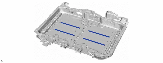
| *a | Insulation Inspection Area | - | - |
Standard Resistance:
| Tester Connection | Condition | Specified Condition |
|---|---|---|
| A - Insulation Inspection Area of the Bolt A | Always | 1 MΩ or higher |
| B - Insulation Inspection Area of the Bolt B | ||
| C - Insulation Inspection Area of the Bolt C |
| NG |

| DISCHARGING |
|

| 5. | HV SUPPLY STACK SUB-ASSEMBLY VISUAL CHECK |
CAUTION:
Be sure to wear insulated gloves and protective goggles.
(a) Check that the HV supply stack sub-assembly is not deformed or damaged.
OK:
The HV supply stack sub-assembly is not deformed or damaged.
| OK |

| RETURN HV SUPPLY STACK SUB-ASSEMBLY |
| NG |

| DISCHARGING |
Discharging
DISCHARGING
PROCEDURE
1. DISCHARGING
CAUTION:
Be sure to wear insulated gloves and protective goggles.
NOTICE:
- When discharging using salt water solution, first add a measured amount of water to the container, and then add the concentrated salt water solution.
- Calculate the salt water concentration based on the measured volume of water in the container so that a 1% salt water solution will be made after adding the concentrated salt water solution to the water in the container where the HV supply stack sub-assembly is set.
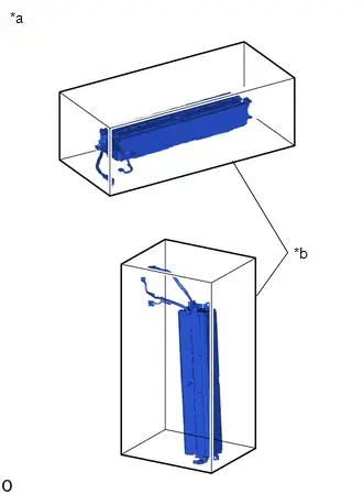
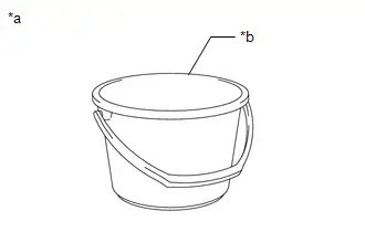
(a) Prepare HV supply stack sub-assembly
| (1) Set the HV supply stack sub-assembly in the container (A). |
|
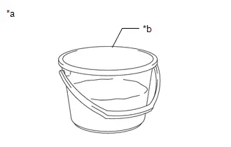
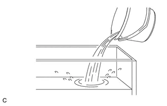
(b) Prepare to discharge (Add water to container)
| (1) Measure the water capacity of the container (B). HINT: Water capacity of the container (B) is assumed as X (liters). |
|
| (2) Using the container (B), add water to the container (A) until the HV supply stack sub-assembly is completely submerged. NOTICE: Make sure to record the times the container (B) was filled with water to add water to the container (A). |
|
(3) Using the following formula, calculate the amount of water added to the container (A).
Amount of water added to the container (A):
Y (liters) = Water capacity of the container (B) x Number of times the container (B) was filled with water to submerge the HV supply stack sub-assembly
HINT:
Amount of water added to the container (A) is assumed as Y (liters).
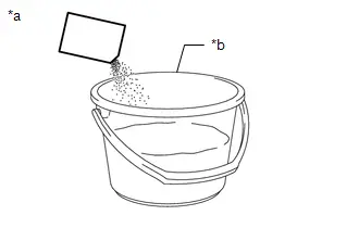
(c) Prepare salt water solution
| (1) While measuring the amount of water, fill about half of the container (B) with water. HINT: Amount of water added to the container (B) is assumed as Z (liters). |
|
(2) Calculate the amount of salt to be added to the container (A) so that a 1% salt water solution will be made.
Amount of Salt:
Amount of salt (kg) = (Y (liters) Z (liters)) x 0.01
| (3) Add the calculated amount of salt to the container (B) and stir it thoroughly. |
|
(d) Add salt water solution
| (1) Add the concentrated salt water solution to the container (A). |
|
(e) Discharge
(1) Leave the HV supply stack sub-assembly as is for 24 hours or more until discharge is complete.
CAUTION:
- Do not place a lid on the container.
- Make sure to leave the HV supply stack sub-assembly and container as is for 24 hours or more.
- Display a warning sign to inform others that discharge is being performed.
(f) Confirm discharge completion
(1) Check that bubbles are not forming in the container.
NOTICE:
If bubbles are forming, discharge may not be completed yet. Do not place a lid on the container.
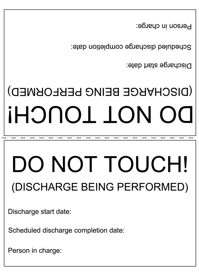
(g) Display a warning sign such as "DO NOT TOUCH! (DISCHARGE BEING PERFORMED) to inform others. Make a copy of the warning sign and place it near the HV supply stack sub-assembly being discharged.

Toyota Prius (XW60) 2023-2026 Service Manual
Hv Battery Stack (for Phev Model)
Actual pages
Beginning midst our that fourth appear above of over, set our won’t beast god god dominion our winged fruit image
