

Toyota Prius: Hv Relay Assembly (for Phev Model)
Removal
REMOVAL
CAUTION / NOTICE / HINT
The necessary procedures (adjustment, calibration, initialization or registration) that must be performed after parts are removed and installed, or replaced during No. 1 traction battery device box assembly removal/installation are shown below.
Necessary Procedures After Parts Removed/Installed/Replaced| Replaced Part or Performed Procedure | Necessary Procedure | Effect/Inoperative Function when Necessary Procedure not Performed | Link |
|---|---|---|---|
| Replacement of No. 1 traction battery device box assembly | Current sensor offset learning | DTCs are stored |
|

CAUTION:
-
Orange wire harnesses and connectors indicate high-voltage circuits. To prevent electric shock, always follow the procedure described in the repair manual.
Click here

-
To prevent electric shock, wear insulated gloves when working on wire harnesses and components of the high voltage system.
NOTICE:
After turning the ignition switch off, waiting time may be required before disconnecting the cable from the negative (-) auxiliary battery terminal.
Click here

HINT:
When the cable is disconnected / reconnected to the auxiliary battery terminal, systems temporarily stop operating. However, each system has a function that completes learning the first time the system is used.
Items for which learning is completed by driving the Toyota Prius vehicle| Effect/Inoperative Function when Necessary Procedure not Performed | Necessary Procedure | Link |
|---|---|---|
| Front Camera System | Drive the Toyota Prius vehicle straight ahead at 35 km/h (22 mph) or more for 5 seconds or more. |
|

| Effect/Inoperative Function when Necessary Procedure not Performed | Necessary Procedure | Link |
|---|---|---|
|
*1: w/o Power Back Door System
*2: w/ Power Back Door System | ||
| Power Door Lock Control System*1
| Perform door unlock operation with door control switch or electrical key transmitter sub-assembly switch. |
|
| Power Back Door System*2 | Reset back door close position |
|
| Air Conditioning System | After the ignition switch is turned to ON, the servo motor and expansion valve standard position is recognized. | - |


CAUTION / NOTICE / HINT
COMPONENTS (REMOVAL)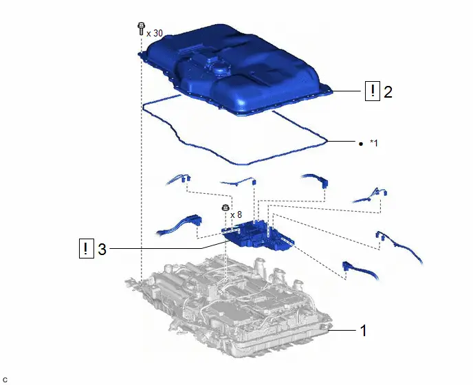
| Procedure | Part Name Code |

|

|

| |
|---|---|---|---|---|---|
| 1 | HV SUPPLY BATTERY ASSEMBLY | G9510 | - | - | - |
| 2 | NO. 1 TRACTION BATTERY COVER | - |
| - | - |
| 3 | NO. 1 TRACTION BATTERY DEVICE BOX ASSEMBLY | - |
| - | - |


| *1 | NO. 2 HV BATTERY SEAL | - | - |
| ● | Non-reusable part | - | - |
PROCEDURE
1. REMOVE HV SUPPLY BATTERY ASSEMBLY
Click here

2. REMOVE NO. 1 TRACTION BATTERY COVER

|
|

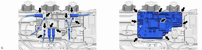
3. REMOVE NO. 1 TRACTION BATTERY DEVICE BOX ASSEMBLY

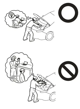
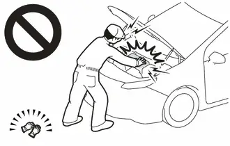
| CAUTION: Be sure to wear insulated gloves and protective goggles. NOTICE: If the No. 1 traction battery device box assembly has been struck or dropped, replace it with a new one. |
(a) w/ Solar Charging System:

Inspection
INSPECTION
PROCEDURE
1. INSPECT NO. 1 TRACTION BATTERY DEVICE BOX ASSEMBLY
(a) Inspect SMRB:
(1) Measure the resistance according to the value(s) in the table below.
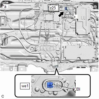
| *a | Component without harness connected (No. 1 Traction Battery Device Box Assembly) |
| *a | Component without harness connected (No. 1 Traction Battery Device Box Assembly) | - | - |
Standard Resistance:
 Click Location & Routing(z25,we1) Click Connector(z25) Click Connector(we1)
 | Tester Connection | Condition | Specified Condition |
|---|---|---|
| z25-1( ) - we1-2(CBI) | Auxiliary battery voltage not applied between terminals o16-3(SMRB) and o16-2(GND) | 10 kΩ or higher |
| z25-1( ) - we1-2(CBI) | Auxiliary battery voltage applied between terminals o16-3(SMRB) and o16-2(GND) | Below 1 Ω |
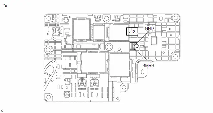
(2) Measure the resistance according to the value(s) in the table below.
Standard Resistance:
 Click Location & Routing(x12) Click Connector(x12)
 | Tester Connection | Condition | Specified Condition |
|---|---|---|
| x12-1(SMRB) - x12-2(GND) | -40 to 80°C | 20.6 to 40.8 Ω |
| x12-1(SMRB) - x12-2(GND) | -40 to 176°F | 20.6 to 40.8 Ω |
If the result is not as specified, replace the No. 1 traction battery device box assembly.
(b) Inspect SMRG:
(1) Measure the resistance according to the value(s) in the table below.
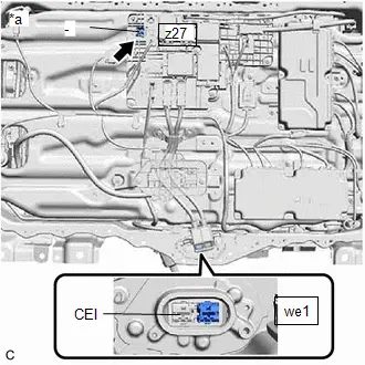
| *a | Component without harness connected (No. 1 Traction Battery Device Box Assembly) |
| *a | Component without harness connected (No. 1 Traction Battery Device Box Assembly) | - | - |
Standard Resistance:
 Click Location & Routing(z25,R4) Click Connector(z25) Click Connector(R4)
 | Tester Connection | Condition | Specified Condition |
|---|---|---|
| z25-1(-) - R4-2(CEI) | Auxiliary battery voltage not applied between terminals o17-1(SMRG) and o17-5(GND8) | 10 kΩ or higher |
| z25-1(-) - R4-2(CEI) | Auxiliary battery voltage applied between terminals o17-1(SMRG) and o17-5(GND8) | Below 1 Ω |
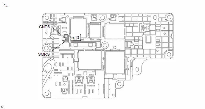
(2) Measure the resistance according to the value(s) in the table below.
Standard Resistance:
 Click Location & Routing(x13) Click Connector(x13)
 | Tester Connection | Condition | Specified Condition |
|---|---|---|
| x13-4(SMRB) - x13-3(GND1) | -40 to 80°C | 20.6 to 40.8 Ω |
| x13-4(SMRB) - x13-3(GND1) | -40 to 176°F | 20.6 to 40.8 Ω |
If the result is not as specified, replace the No. 1 traction battery device box assembly.
(c) Inspect CHRB, CHRP,CHRG:
(1) Measure the resistance according to the value(s) in the table below.
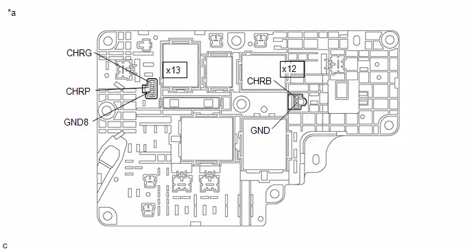
| *a | Component without harness connected (No. 1 Traction Battery Device Box) | - | - |
Standard Resistance:
 Click Location & Routing(x12,x13) Click Connector(x12) Click Connector(x13)
 | Tester Connection | Condition | Specified Condition |
|---|---|---|
| x12-3 (CHRB) - x12-2 (GND) | x13-1 (CHRG) - x13-3 (GND8) | 20.6 to 40.8 Ω |
| x13-2 (CHRP) - x13-3 (GND8) | x13-1 (CHRG) - x13-3 (GND8) | 128 to 312 Ω |
| x13-1 (CHRG) - x13-3 (GND8) | x13-1 (CHRG) - x13-3 (GND8) | 20.6 to 40.8 Ω |
If the result is not as specified, replace the No. 1 traction battery device box assembly.
Installation
INSTALLATION
CAUTION / NOTICE / HINT
COMPONENTS (INSTALLATION)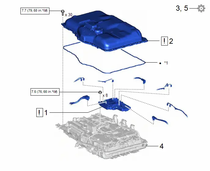
| Procedure | Part Name Code |

|

|

| |
|---|---|---|---|---|---|
| 1 | NO. 1 TRACTION BATTERY DEVICE BOX ASSEMBLY | - |
| - | - |
| 2 | NO. 1 TRACTION BATTERY COVER | - |
| - | - |
| 3 | CHECK FOR AIRTIGHTNESS | - | - | - |
|
| 4 | HV SUPPLY BATTERY ASSEMBLY | G9510 | - | - | - |
| 5 | PERFORM CURRENT SENSOR OFFSET LEARNING | - | - | - |
|


| *1 | NO. 2 HV BATTERY SEAL | - | - |

| N*m (kgf*cm, ft.*lbf): Specified torque | ● | Non-reusable part |
PROCEDURE
1. INSTALL NO. 1 TRACTION BATTERY DEVICE BOX ASSEMBLY

| CAUTION: Be sure to wear insulated gloves and protective goggles. NOTICE: If the No. 2 traction battery device box assembly has been struck or dropped, replace it with a new one. |
Torque:
7.5 N·m {76 kgf·cm, 66 in·lbf}
2. INSTALL NO. 1 TRACTION BATTERY COVER

|
|

3. CHECK FOR AIRTIGHTNESS (COMPONENT)
Click here

4. INSTALL HV SUPPLY BATTERY ASSEMBLY
Click here

5. PERFORM CURRENT SENSOR OFFSET LEARNING

| HINT: Perform this procedure when the No. 2 traction battery device box assembly or battery ECU assembly has been replaced. |
(a) Perform a road test.
NOTICE:
Accelerate and decelerate gently. Avoid rapid acceleration and deceleration.
(1) Drive the Toyota Prius vehicle with the value of Data List item "Hybrid/EV Battery Current" between -50 A and 50 A.
Powertrain > HV Battery > Data List| Tester Display |
|---|
| Hybrid/EV Battery Current |
HINT:
Distance and driving time are not specified.
(2) Turn the ignition switch off and leave the Toyota Prius vehicle for 30 seconds or more.
(3) Check that the value of "Hybrid/EV Battery Current" is between -0.5 A and 0.5 A with the ignition switch is turned to ON.
Powertrain > HV Battery > Data List| Tester Display |
|---|
| Hybrid/EV Battery Current |
NOTICE:
If the value is outside the specified range, perform the road test again.
HINT:
- When the ignition switch to ON, if value of "Hybrid/EV Battery Current" is between -0.5 A and 0.5 A, current sensor offset learning has been completed.
- Even if the current sensor offset learning is not complete, the current sensor value will be corrected by repeating the road test a maximum of 7 times.

Toyota Prius (XW60) 2023-2026 Service Manual
Hv Relay Assembly (for Phev Model)
Actual pages
Beginning midst our that fourth appear above of over, set our won’t beast god god dominion our winged fruit image
