

Toyota Prius: Hood
On-vehicle Inspection
ON-VEHICLE INSPECTION
PROCEDURE
1. INSPECT HOOD SUB-ASSEMBLY
(a) Check that the clearance measurements of areas a through g are within each standard range.
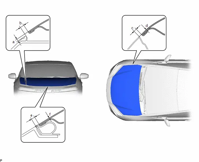 Standard Clearance
 | Area | Measurement | Area | Measurement |
|---|---|---|---|
| a | 0.4 to 4.4 mm (0.016 to 0.173 in.) | b | 2.7 to 6.7 mm (0.106 to 0.264 in.) |
| c | 2.5 to 5.5 mm (0.098 to 0.217 in.) | d | -1.5 to 1.5 mm (-0.059 to 0.059 in.) |
| e | 2.0 to 6.0 mm (0.079 to 0.236 in.) | f | -2.0 to 2.0 mm (-0.079 to 0.079 in.) |
Disassembly
DISASSEMBLY
CAUTION / NOTICE / HINT
COMPONENTS (DISASSEMBLY)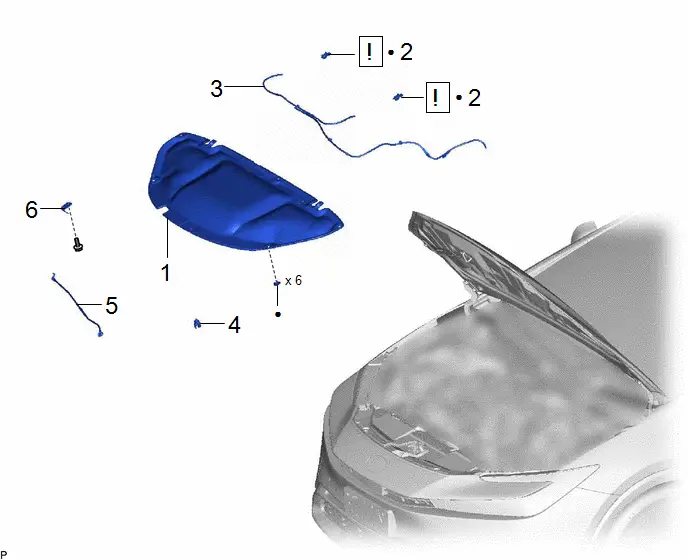
| Procedure | Part Name Code |

|

|

| |
|---|---|---|---|---|---|
| 1 | HOOD INSULATOR | 53341B | - | - | - |
| 2 | WASHER NOZZLE SUB-ASSEMBLY | 85035 |
| - | - |
| 3 | WASHER HOSE ASSEMBLY | - | - | - | - |
| 4 | HOOD STAY HOLDER | 53452 | - | - | - |
| 5 | HOOD SUPPORT ROD | 53451 | - | - | - |
| 6 | HOOD STAY BRACKET | 53336A | - | - | - |

| ● | Non-reusable part | - | - |
PROCEDURE
1. REMOVE HOOD INSULATOR

2. REMOVE WASHER NOZZLE SUB-ASSEMBLY

| Click here
|

3. DISCONNECT WASHER HOSE ASSEMBLY

4. REMOVE HOOD STAY HOLDER

5. REMOVE HOOD SUPPORT ROD

6. REMOVE HOOD STAY BRACKET

Reassembly
REASSEMBLY
CAUTION / NOTICE / HINT
| Procedure | Part Name Code |

|

|

| |
|---|---|---|---|---|---|
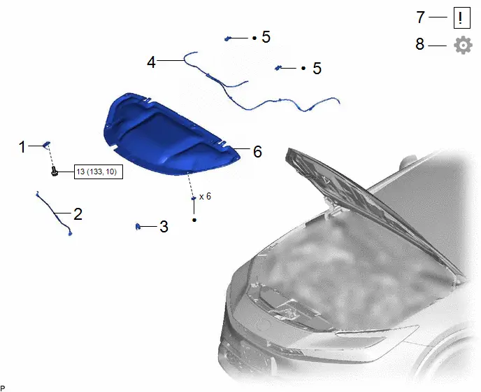
| 1 | HOOD STAY BRACKET | 53336A | - | - | - |
| 2 | HOOD SUPPORT ROD | 53451 | - | - | - |
| 3 | HOOD STAY HOLDER | 53452 | - | - | - |
| 4 | WASHER HOSE ASSEMBLY | - | - | - | - |
| 5 | WASHER NOZZLE SUB-ASSEMBLY | 85035 | - | - | - |
| 6 | HOOD INSULATOR | 53341B | - | - | - |
| 7 | INSPECT WASHER NOZZLE SUB-ASSEMBLY | 85035 |
| - | - |
| 8 | ADJUST WASHER NOZZLE SUB-ASSEMBLY | 85035 | - | - |
|


| N*m (kgf*cm, ft.*lbf): Specified torque | ● | Non-reusable part |
PROCEDURE
1. INSTALL HOOD STAY BRACKET
Torque:
13 N·m {133 kgf·cm, 10 ft·lbf}
2. INSTALL HOOD SUPPORT ROD
3. INSTALL HOOD STAY HOLDER
4. CONNECT WASHER HOSE ASSEMBLY
5. INSTALL WASHER NOZZLE SUB-ASSEMBLY
6. INSTALL HOOD INSULATOR
7. INSPECT WASHER NOZZLE SUB-ASSEMBLY

| Click here
|

8. ADJUST WASHER NOZZLE SUB-ASSEMBLY
Click here

Adjustment
ADJUSTMENT
CAUTION / NOTICE / HINT
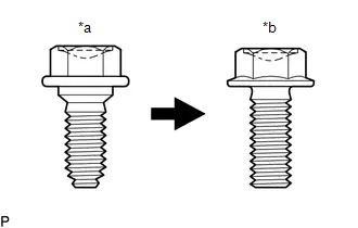
| *a | Centering Bolt |
| *b | Standard Bolt |
HINT:
- Centering bolts are used to install the hood hinges and hood lock. The hood and hood lock cannot be adjusted with the centering bolts installed. Substitute the centering bolts with standard bolts (with washers) when making adjustments.
-
The specified torque for standard bolts is shown in the standard bolt chart.
Click here

PROCEDURE
1. INSPECT HOOD SUB-ASSEMBLY
Click here

2. ADJUST HOOD SUB-ASSEMBLY
(a) Horizontally and vertically adjust the hood.
| (1) Loosen the 4 hinge bolts of the hood. |
|
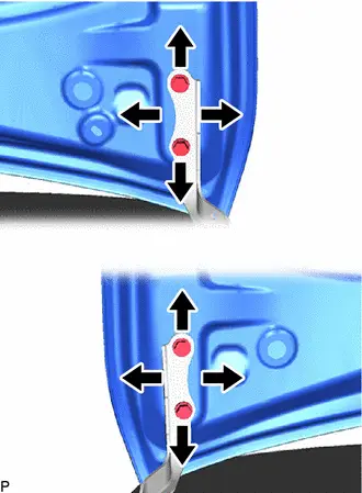
(2) Adjust the clearance between the hood and front fenders by moving the hood.
(3) Tighten the 4 hinge bolts after adjustment.
Torque:
13 N·m {133 kgf·cm, 10 ft·lbf}
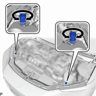
(b) Adjust the height of the front end of the hood using the hood bumper cushions.
| (1) Adjust the 2 hood bumper cushions so that the heights of the hood and fenders are aligned. HINT: Raise or lower the front end of the hood by turning the 2 hood bumper cushions. |
|
(c) Adjust the hood lock.
(1) Remove the radiator support opening cover.
Click here

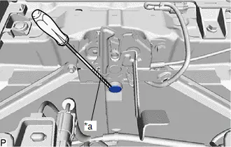
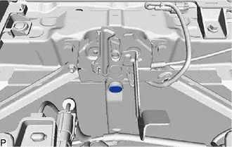
| (2) Using a screwdriver with its tip wrapped with protective tape, remove the hood lock nut cap. |
|
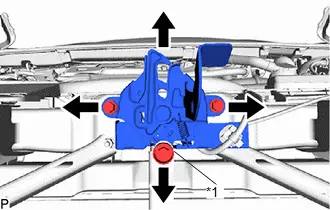
| (3) Loosen the 2 bolts and hood lock bolt. |
|
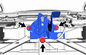
| (4) Adjust the hood lock assembly and tighten the 3 bolts. Torque: 8.0 N·m {82 kgf·cm, 71 in·lbf} |
|
(5) Check that the striker can engage the hood lock assembly smoothly.
| (6) Install a new hood lock nut cap. |
|
(7) Install the radiator support opening cover.

Toyota Prius (XW60) 2023-2026 Service Manual
Hood
Actual pages
Beginning midst our that fourth appear above of over, set our won’t beast god god dominion our winged fruit image
