

Toyota Prius: Fuel Lid Opener System
- Precaution
- Parts Location
- System Diagram
- System Description
- How To Proceed With Troubleshooting
- Operation Check
- Problem Symptoms Table
- Terminals Of Ecu
- Data List / Active Test
- Fuel Lid Opener does not Operate
Precaution
PRECAUTION
PRECAUTIONS FOR DISCONNECTING CABLE FROM NEGATIVE (-) AUXILIARY BATTERY TERMINAL
NOTICE:
After the ignition switch is turned off, there may be a waiting time before disconnecting the negative (-) auxiliary battery terminal.
Click here

HINT:
When disconnecting and reconnecting the auxiliary battery, there is an automatic learning function that completes learning when the respective system is used.
Click here


PRECAUTIONS FOR REMOVAL, INSTALLATION AND REPLACEMENT OF COMPONENTS
(a) After replacing certain components, it may be necessary to update the ECU security key.
Click here


Parts Location
PARTS LOCATION
ILLUSTRATION
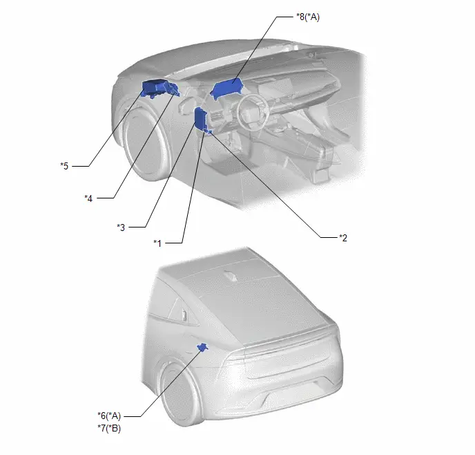
| *A | for M20A-FXS | *B | for 2ZR-FXE |
| *1 | FUEL LID OPENER SWITCH | *2 | DLC3 |
| *3 | POWER DISTRIBUTION BOX ASSEMBLY - FUEL OPN FUSE - FUEL OPN RELAY/FUEL LOCK RELAY | *4 | ECM |
| *5 | NO.1 ENGINE ROOM RELAY BLOCK AND NO.1 JUNCTION BLOCK ASSEMBLY - EFI NO.3 FUSE | *6 | FUEL LID WITH MOTOR LOCK ASSEMBLY - FUEL LID COURTESY SWITCH |
| *7 | FUEL LID WITH MOTOR LOCK ASSEMBLY | *8 | COMBINATION METER ASSEMBLY |
System Diagram
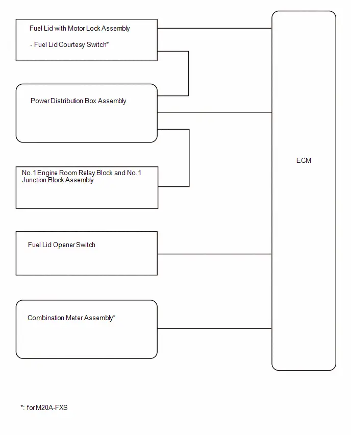
SYSTEM DIAGRAM
System Description
SYSTEM DESCRIPTION
for M20A-FXS
When the fuel lid opener switch is operated, the pressure in the fuel tank is decreased and a message is displayed on the multi-information display. After the pressure has decreased, the ECM turns on the FUEL OPN relay/FUEL LOCK relay to operate the fuel lid with motor lock assembly to open the fuel lid. When the fuel lid is opened, a fuel lid courtesy switch signal is output and a message is displayed on the multi-information display.
for 2ZR-FXE
When the fuel lid opener switch is operated, the fuel lid with motor lock assembly opens the fuel lid.
How To Proceed With Troubleshooting
CAUTION / NOTICE / HINT
HINT:
- Use the following procedure to troubleshoot the fuel lid opener system.
- *: Use the GTS.
PROCEDURE
| 1. | Toyota Prius Vehicle BROUGHT TO WORKSHOP |
|

| 2. | CUSTOMER PROBLEM ANALYSIS |
HINT:
- In troubleshooting, confirm that the problem symptoms have been accurately identified. Preconceptions should be discarded in order to make an accurate judgment. To clearly understand what the problem symptoms are, it is extremely important to ask the customer about the problem and the conditions at the time the malfunction occurred.
- Gather as much information as possible for reference. Past problems that seem unrelated may also help in some cases.
-
The following 5 items are important points for problem analysis:
What
Toyota Prius Vehicle model, system name
When
Date, time, occurrence frequency
Where
Road conditions
Under what conditions?
Driving conditions, weather conditions
How did it happen?
Problem symptoms
|

| 3. | INSPECT AUXILIARY BATTERY VOLTAGE |
(a) Measure the auxiliary battery voltage with the ignition switch off.
Standard voltage:
11 to 14 V
HINT:
- A simple method to determine whether the auxiliary battery is discharged is to operate the horn.
- If the voltage is below 11 V, recharge or replace the auxiliary battery before proceeding.
(b) Check the fuses and relays.
(c) Check the connector connections and terminals to make sure that there are no abnormalities such as loose connections, deformation, etc.
|

| 4. | SYSTEM CHECK |
(a) Check the Toyota Prius vehicle specification.
| Result | Proceed to |
|---|---|
| for M20A-FXS | A |
| for 2ZR-FXE | B |
| B |

| GO TO STEP 6 |
|

| 5. | CHECK FOR DTC* |
(a) Clear the DTCs.
Powertrain > Engine > Clear DTCs(b) Check for SFI system DTCs.
Powertrain > Engine > Trouble CodesOK:
SFI system DTCs are not output.
| NG |

| GO TO SFI SYSTEM |
|

| 6. | PROBLEM SYMPTOMS TABLE |
(a) Refer to Problem Symptoms Table.
Click here

| Result | Proceed to |
|---|---|
| Fault is not listed in Problem Symptoms Table | A |
| Fault is listed in Problem Symptoms Table | B |
| B |

| ADJUST, REPAIR OR REPLACE IN ACCORDANCE WITH PROBLEM SYMPTOMS TABLE |
|

| 7. | OVERALL ANALYSIS AND TROUBLESHOOTING* |
(a) Data List / Active Test
Click here

(b) Operation Check
Click here

(c) Terminals of ECU
Click here

(d) Inspection
|

| 8. | REPAIR OR REPLACE |
|

| 9. | CONFIRMATION TEST |
| NEXT |

| END |
Operation Check
OPERATION CHECK
CHECK FUEL LID OPENER SYSTEM
(a) Push the fuel lid opener switch and check that messages are displayed on the multi-information display in the combination meter assembly and the fuel lid opens.*1
(b) Push the fuel lid opener switch and check that the fuel lid opens.*2
- *1: for M20A-FXS
- *2: for 2ZR-FXE
Problem Symptoms Table
PROBLEM SYMPTOMS TABLE
NOTICE:
- When replacing the combination meter assembly, always replace it with a new one. If a combination meter assembly which was installed to another vehicle is used, the information stored in it will not match the information from the Toyota Prius vehicle and a DTC may be stored.
-
After replacing combination meter assembly, it may be necessary to update the ECU security key.
Click here
HINT:
- If a malfunction occurs in the close tank valve assembly or vapor pressure sensor, the fuel lid opener does not operate due to ECM control.
- If the fuel lid opener operates after a short time, the close tank valve assembly or fuel tank vent hose may be clogged.
| Symptom | Suspected Area | Link |
|---|---|---|
| Fuel lid opener does not operate | Proceed to "Fuel Lid Opener does not Operate" |
|
| Messages are not displayed on the multi-information display in the combination meter assembly | Harness or connector | - |
| Combination meter assembly |
| |
| ECM |
|


| Symptom | Suspected Area | Link |
|---|---|---|
| Fuel lid opener does not operate | Proceed to "Fuel Lid Opener does not Operate" |
|

Terminals Of Ecu
TERMINALS OF ECU
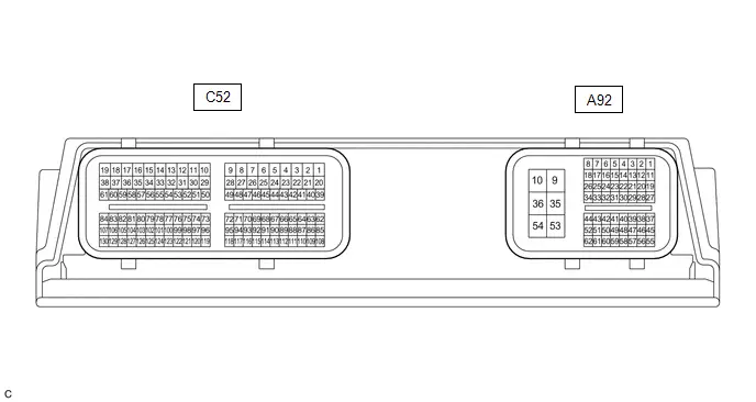
CHECK ECM (for M20A-FXS)
HINT:
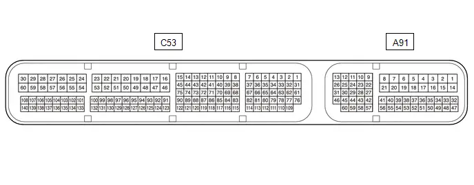
The standard voltage and waveform between each pair of the ECM terminals are shown in the table below. The appropriate conditions for checking each pair of the terminals is also indicated. The result of checks should be compared with the standard voltage, resistance and waveform for each pair of the terminals as displayed in the Specified Condition column. The illustration above can be used as a reference to identify the ECM terminal locations.
| Terminal No. (Symbol) | Terminal Description | Condition | Specified Condition |
|---|---|---|---|
| A92-31 (LIDO) - A92-10 (E1) | Fuel lid with motor lock assembly (fuel lid courtesy switch) signal | Fuel lid closed | Below 1 V |
| Fuel lid open | 11 to 14 V | ||
| A92-38 (FUEL) - A92-10 (E1) | Fuel lid opener switch signal | fuel lid opener switch pressed | Below 1 V |
| fuel lid opener switch not pressed | 11 to 14 V | ||
| A92-41 (LSTM) - A92-10 (E1) | Fuel lid operation signal for combination meter assembly | "Close Fuel Lid" displayed on multi-information display | Pulse generation (see waveform 1) |
| "Ready to Refuel" displayed on multi-information display | Pulse generation (see waveform 2) | ||
| "Please Wait Fuel Door Opening" displayed on multi-information display | Pulse generation (see waveform 3) | ||
| A92-44 (FREL) - A92-10 (E1) | Fuel lid with motor lock assembly operation signal | Fuel lid with motor lock assembly operating | Below 1 V |
| Fuel lid with motor lock assembly not operating | 11 to 14 V |
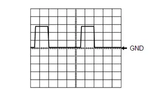
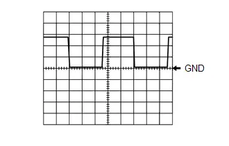
(a) Using an oscilloscope, check waveform 1.
Waveform 1 (Reference)| Item | Content |
|---|---|
| Terminal No. (Symbol) | A92-41 (LSTM) - A92-10 (E1) |
| Tool Setting | 5 V/DIV., 20 ms./DIV. |
| Condition | "Close Fuel Lid" displayed on multi-information display |

HINT:
This waveform is output when the fuel lid opener switch is operated if the fuel lid is open and any of the following conditions are met:
- The Toyota Prius vehicle has been driven for 1 km (0.6 mile) or more at a speed of 50 km/h (31 mph) or more.
- 30 minutes or more have elapsed since the fuel lid opener switch was operated.
(b) Using an oscilloscope, check waveform 2.
Waveform 2 (Reference)| Item | Content |
|---|---|
| Terminal No. (Symbol) | A92-41 (LSTM) - A92-10 (E1) |
| Tool Setting | 5 V/DIV., 20 ms./DIV. |
| Condition | "Ready to Refuel" displayed on multi-information display |

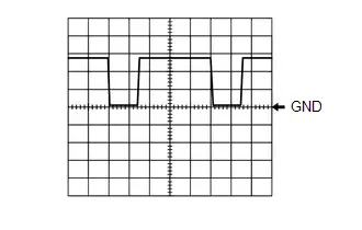
(c) Using an oscilloscope, check waveform 3.
Waveform 3 (Reference)| Item | Content |
|---|---|
| Terminal No. (Symbol) | A92-41 (LSTM) - A92-10 (E1) |
| Tool Setting | 5 V/DIV., 20 ms./DIV. |
| Condition | "Please Wait Fuel Door Opening" displayed on multi-information display |
HINT:
This waveform is output when the internal pressure of the fuel tank is higher than the ambient pressure when the fuel lid opener switch is operated.
CHECK ECM (for 2ZR-FXE)
HINT:
The standard voltage and waveform between each pair of the ECM terminals are shown in the table below. The appropriate conditions for checking each pair of the terminals is also indicated. The result of checks should be compared with the standard voltage, resistance and waveform for each pair of the terminals as displayed in the Specified Condition column. The illustration above can be used as a reference to identify the ECM terminal locations.
| Terminal No. (Symbol) | Terminal Description | Condition | Specified Condition |
|---|---|---|---|
| A91-60 (FUEL) - A91-17 (E1) | Fuel lid opener switch signal | fuel lid opener switch pressed | Below 1 V |
| fuel lid opener switch not pressed | 11 to 14 V | ||
| A91-28 (FREL) - A91-17 (E1) | Fuel lid with motor lock assembly operation signal | Fuel lid with motor lock assembly operating | Below 1 V |
| Fuel lid with motor lock assembly not operating | 11 to 14 V |
CHECK COMBINATION METER ASSEMBLY (for M20A-FXS)
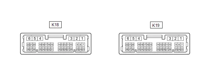
(a) Disconnect the K18 combination meter assembly connector.
(b) Measure the voltage and resistance according to the value(s) in the table below.
| Terminal No. | Terminal Description | Condition | Specified Condition |
|---|---|---|---|
| K18-5 (B) - Body ground | Auxiliary battery | Ignition switch off | 11 to 14 V |
| K18-6 (IG ) - Body ground | Ignition switch signal | Ignition switch off | Below 1 V |
| Ignition switch ON | 11 to 14 V | ||
| K18-1 (EP) - Body ground | Ground | Always | Below 1 Ω |
| K18-2 (ES) - Body ground | Ground | Always | Below 1 Ω |
(c) Reconnect the K18 combination meter assembly connector.
(d) Measure the waveform according to the value(s) in the table below.
| Terminal No. (Symbol) | Terminal Description | Condition | Specified Condition |
|---|---|---|---|
| K18-28 (LST1) - Body ground | Fuel lid operation signal for combination meter assembly | "Close Fuel Lid" displayed on multi-information display | Pulse generation (see waveform 1) |
| "Ready to Refuel" displayed on multi-information display | Pulse generation (see waveform 2) | ||
| "Please Wait Fuel Door Opening" displayed on multi-information display | Pulse generation (see waveform 3) |
(1) Using an oscilloscope, check waveform 1.
Waveform 1 (Reference)| Item | Content |
|---|---|
| Terminal No. (Symbol) | K18-28 (LST1) - Body ground |
| Tool Setting | 5 V/DIV., 20 ms./DIV. |
| Condition | "Close Fuel Lid" displayed on multi-information display |
HINT:
This waveform is output when the fuel lid opener switch is operated if the fuel lid is open and any of the following conditions are met:
- The Toyota Prius vehicle has been driven for 1 km (0.6 mile) or more at a speed of 50 km/h (31 mph) or more.
- 30 minutes or more have elapsed since the fuel lid opener switch was operated.
(2) Using an oscilloscope, check waveform 2.
Waveform 2 (Reference)| Item | Content |
|---|---|
| Terminal No. (Symbol) | K18-28 (LST1) - Body ground |
| Tool Setting | 5 V/DIV., 20 ms./DIV. |
| Condition | "Ready to Refuel" displayed on multi-information display |
(3) Using an oscilloscope, check waveform 3.
Waveform 3 (Reference)| Item | Content |
|---|---|
| Terminal No. (Symbol) | K18-28 (LST1) - Body ground |
| Tool Setting | 5 V/DIV., 20 ms./DIV. |
| Condition | "Please Wait Fuel Door Opening" displayed on multi-information display |

HINT:
This waveform is output when the internal pressure of the fuel tank is higher than the ambient pressure when the fuel lid opener switch is operated.
Data List / Active Test
DATA LIST / ACTIVE TEST
DATA LIST
HINT:
Using the GTS to read the Data List allows the values or states of switches, sensors, actuators and other items to be read without removing any parts. This non-intrusive inspection can be very useful because intermittent conditions or signals may be discovered before parts or wiring is disturbed. Reading the Data List information early in troubleshooting is one way to save diagnostic time.
NOTICE:
In the table below, the values listed under "Normal Condition" are reference values. Do not depend solely on these reference values when deciding whether a part is faulty or not.
(a) According to the display on the GTS, read the "Data List".
Powertrain > Engine > Data List| Tester Display | Measurement Item | Range | Normal Condition | Diagnostic Note |
|---|---|---|---|---|
| Fuel Filler Opener | Fuel lid with motor lock assembly status | OFF or ON | OFF: Fuel lid with motor lock assembly not operating ON: Fuel lid with motor lock assembly operating | for M20A-FXS |
| Fuel Lid SW | Fuel lid opener switch status | Close or Open | Close: Fuel lid opener switch not pushed Open: Fuel lid opener switch pushed | - |
| Fuel Lid Sensor SW | Fuel lid with motor lock assembly (fuel lid courtesy switch) status | Close or Open | Close: Fuel lid closed Open: Fuel lid open | for M20A-FXS |
ACTIVE TEST
HINT:
Using the GTS to perform Active Tests allows relays, VSVs, actuators and other items to be operated without removing any parts. This non-intrusive functional inspection can be very useful because intermittent operation may be discovered before parts or wiring is disturbed. Performing Active Tests early in troubleshooting is one way to save diagnostic time. Data List information can be displayed while performing Active Tests.
(a) According to the display on GTS perform the "Active Test".
Powertrain > Engine > Active Test| Tester Display | Measurement Item | Control Range | Diagnostic Note |
|---|---|---|---|
| Activate the Fuel Filler Opener | Activate fuel lid with motor lock assembly | OFF or ON | for M20A-FXS |
Fuel Lid Opener does not Operate
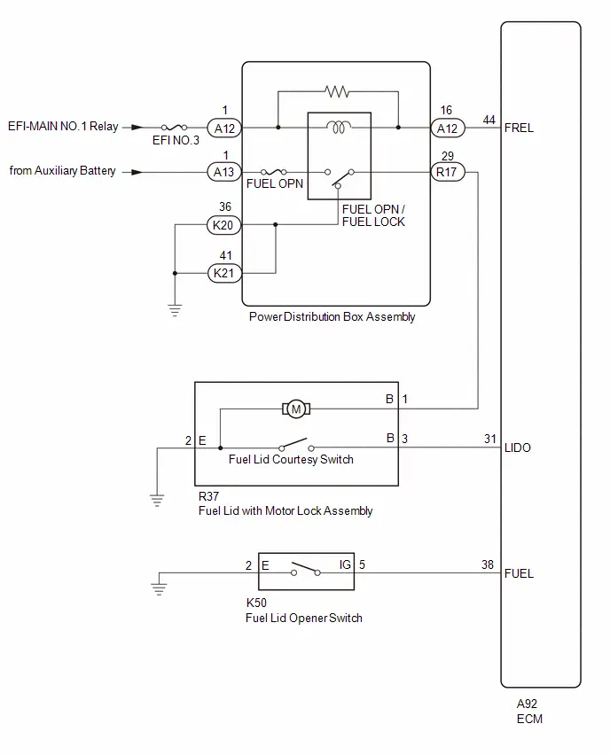
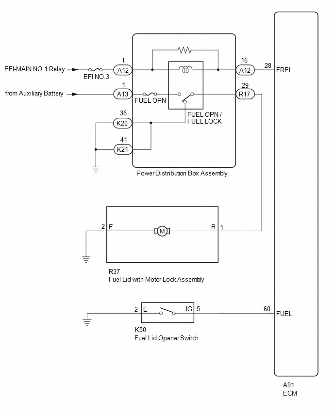
DESCRIPTION
When the fuel lid opener switch is pushed, a fuel lid opener switch signal is sent to the ECM. The ECM turns on the FUEL OPN relay/FUEL LOCK relay and the fuel lid with motor lock assembly opens the fuel lid. When the fuel lid is open, a fuel lid courtesy switch signal is output from the fuel lid with motor lock assembly.
WIRING DIAGRAM
for M20A-FXS
for 2ZR-FXE
CAUTION / NOTICE / HINT
HINT:
- Inspect the fuses for circuits related to this system before performing the following procedure.
- If a malfunction occurs in the close tank valve assembly or vapor pressure sensor, the fuel lid opener does not operate due to ECM control.
- If the fuel lid opener operates after a short time, the close tank valve assembly or fuel tank vent hose may be clogged.
PROCEDURE
| 1. | CONFIRM MODEL |
(a) Choose the model to be inspected.
| Result | Proceed to |
|---|---|
| for M20A-FXS | A |
| for 2ZR-FXE | B |
| B |

| GO TO STEP 16 |
|

| 2. | CHECK FOR DTC |
(a) Using the GTS, check that DTCs related to the close tank valve assembly or vapor pressure sensor are not output.
Powertrain > Engine > Trouble Codes| Result | Proceed to |
|---|---|
| DTCs related to the close tank valve assembly or vapor pressure sensor are not output | A |
| DTCs related to the close tank valve assembly or vapor pressure sensor are output | B |
| B |

| GO TO RELEVANT DIAGNOSTIC TROUBLE CODE PROCEDURE
|


|

| 3. | PERFORM ACTIVE TEST USING GTS |
(a) Perform the Active Test according to the display on the GTS.
Powertrain > Engine > Active Test| Tester Display | Measurement Item | Control Range | Diagnostic Note |
|---|---|---|---|
| Activate the Fuel Filler Opener | Activate fuel lid with motor lock assembly | OFF or ON | - |
| Tester Display |
|---|
| Activate the Fuel Filler Opener |
OK:
The fuel lid with motor lock assembly operates normally.
| NG |

| GO TO STEP 11 |
|

| 4. | READ VALUE USING GTS (Fuel Lid SW) |
(a) Enter the following menus: Powertrain / Engine / Data List.
(b) Read the Data List according to the display on the GTS.
Powertrain > Engine > Data List| Tester Display | Measurement Item | Range | Normal Condition | Diagnostic Note |
|---|---|---|---|---|
| Fuel Lid SW | Fuel lid opener switch status | Close or Open | Close: Fuel lid opener switch not pushed Open: Fuel lid opener switch pushed | - |
| Tester Display |
|---|
| Fuel Lid SW |
OK:
The GTS display changes correctly in response to the operation of the fuel lid opener switch.
| NG |

| GO TO STEP 9 |
|

| 5. | READ VALUE USING GTS (FUEL LID SENSOR SW) |
(a) Read the Data List according to the display on the GTS.
Powertrain > Engine > Data List| Tester Display | Measurement Item | Range | Normal Condition | Diagnostic Note |
|---|---|---|---|---|
| Fuel Lid Sensor SW | Fuel lid courtesy switch status | Close or Open | Close: Fuel lid closed Open: Fuel lid open | - |
| Tester Display |
|---|
| Fuel Lid Sensor SW |
OK:
The GTS display changes correctly in response to the operation of the fuel lid courtesy switch (fuel lid with motor lock assembly).
| NG |

| GO TO STEP 7 |
|

| 6. | CHECK CLOSE TANK VALVE ASSEMBLY OR FUEL TANK VENT HOSE |
(a) Check the close tank valve assembly or fuel tank vent hose for clogging.
Click here


OK:
The close tank valve assembly or fuel tank vent hose is not clogged.
| OK |

| REPLACE ECM
|


| NG |

| REMOVE THE CLOGGING |
| 7. | INSPECT FUEL LID WITH MOTOR LOCK ASSEMBLY (FUEL LID COURTESY SWITCH) |
(a) Remove the fuel lid with motor lock assembly.
Click here


(b) Inspect the fuel lid with motor lock assembly.
Click here

| NG |

| REPLACE FUEL LID LOCK WITH MOTOR ASSEMBLY
|


|

| 8. | CHECK HARNESS AND CONNECTOR (FUEL LID WITH MOTOR LOCK ASSEMBLY - ECM) |
(a) Disconnect the A92 ECM connector.
(b) Disconnect the R37 fuel lid with motor lock assembly connector.
(c) Measure the resistance according to the value(s) in the table below.
Standard Resistance:
 Click Location & Routing(R37,A92) Click Connector(R37) Click Connector(A92)
 | Tester Connection | Condition | Specified Condition |
|---|---|---|
| R37-3 (B) - A92-31 (LIDO) | Always | Below 1 Ω |
| R37-3 (B) or A92-31 (LIDO) - Body ground | Always | 10 kΩ or higher |
| OK |

| REPLACE ECM
|


| NG |

| REPAIR OR REPLACE HARNESS OR CONNECTOR |
| 9. | INSPECT FUEL LID OPENER SWITCH |
(a) Remove the fuel lid opener switch.
Click here

(b) Inspect the fuel lid opener switch.
Click here

| NG |

| REPLACE FUEL LID OPENER SWITCH |
|

| 10. | CHECK HARNESS AND CONNECTOR (FUEL LID OPENER SWITCH - ECM AND BODY GROUND) |
(a) Disconnect the A92 ECM connector.
(b) Disconnect the K50 fuel lid opener switch connector.
(c) Measure the resistance according to the value(s) in the table below.
Standard Resistance:
 Click Location & Routing(K50,A92) Click Connector(K50) Click Connector(A92)
 | Tester Connection | Condition | Specified Condition |
|---|---|---|
| K50-5 (IG) - A92-38 (FUEL) | Always | Below 1 Ω |
| K50-5 (IG) or A92-38 (FUEL) - Body ground | Always | 10 kΩ or higher |
| K50-2 (E) - Body ground | Always | Below 1 Ω |
| OK |

| REPLACE ECM
|


| NG |

| REPAIR OR REPLACE HARNESS OR CONNECTOR |
| 11. | INSPECT FUEL LID WITH MOTOR LOCK ASSEMBLY (MOTOR OPERATION) |
(a) Remove the fuel lid with motor lock assembly.
Click here


(b) Inspect the fuel lid with motor lock assembly.
Click here

| NG |

| REPLACE FUEL LID WITH MOTOR LOCK ASSEMBLY
|


|

| 12. | CHECK HARNESS AND CONNECTOR (FUEL LID WITH MOTOR LOCK ASSEMBLY - POWER DISTRIBUTION BOX ASSEMBLY AND BODY GROUND) |
(a) Disconnect the R37 fuel lid with motor lock assembly connector.
(b) Disconnect the R17 power distribution box assembly connector.
(c) Measure the resistance according to the value(s) in the table below.
Standard Resistance:
 Click Location & Routing(R37,R17) Click Connector(R37) Click Connector(R17)
 | Tester Connection | Condition | Specified Condition |
|---|---|---|
| R37-1 (B) - R17-29 | Always | Below 1 Ω |
| R37-2 (E) - Body ground | Always | Below 1 Ω |
| R37-1 (B) or R17-29 - Body ground | Always | 10 kΩ or higher |
| NG |

| REPAIR OR REPLACE HARNESS OR CONNECTOR |
|

| 13. | CHECK HARNESS AND CONNECTOR (POWER DISTRIBUTION BOX ASSEMBLY - BATTERY) |
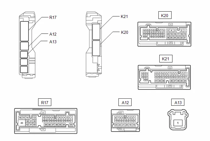
(a) Disconnect the A12, A13, K20 and K21 power distribution box assembly connectors.
(b) Measure the voltage and resistance according to the value(s) in the table below.
Standard Voltage:
 Click Location & Routing(A13,A12) Click Connector(A13) Click Connector(A12)
 | Tester Connection | Switch Condition | Specified Condition |
|---|---|---|
| A13-1 - Body ground | Ignition switch off | 11 to 14 V |
| A12-1 - Body ground | Ignition switch ON | 11 to 14 V |
| Ignition switch off | Below 1 V |
Standard Resistance:
 Click Location & Routing(K20,K21) Click Connector(K20) Click Connector(K21)
 | Tester Connection | Switch Condition | Specified Condition |
|---|---|---|
| K20-36 - Body ground | Always | Below 1 Ω |
| K21-41 - Body ground | Always | Below 1 Ω |
| NG |

| REPAIR OR REPLACE HARNESS OR CONNECTOR |
|

| 14. | CHECK HARNESS AND CONNECTOR (POWER DISTRIBUTION BOX ASSEMBLY - ECM) |
(a) Disconnect the A12 power distribution box assembly connector.
(b) Disconnect the A92 ECM connector.
(c) Measure the resistance according to the value(s) in the table below.
Standard Resistance:
 Click Location & Routing(A12,A92) Click Connector(A12) Click Connector(A92)
 | Tester Connection | Condition | Specified Condition |
|---|---|---|
| A12-16 - A92-44 (FREL) | Always | Below 1 Ω |
| A12-16 or A92-44 (FREL) - Body ground | Always | 10 kΩ or higher |
| NG |

| REPAIR OR REPLACE HARNESS OR CONNECTOR |
|

| 15. | INSPECT POWER DISTRIBUTION BOX ASSEMBLY (FUEL OPN RELAY/FUEL LOCK RELAY) |
(a) Remove the power distribution box assembly.
Click here


(b) Remove the main body ECU (multiplex network body ECU) from the power distribution box assembly.
Click here


(c) Measure the resistance according to the value(s) in the table below.
Standard Resistance:
 Click Location & Routing(A13,R17,K20,K21) Click Connector(A13) Click Connector(R17) Click Connector(K20) Click Connector(K21)
 | Tester Connection | Condition | Specified Condition |
|---|---|---|
| A13-1 - R17-29 | Voltage applied between terminals A12-1 and A12-16 | Below 1 Ω |
| A13-1 - R17-29 | Voltage not applied between terminals A12-1 and A12-16 | 10 kΩ or higher |
| K20-36 - R17-29 | Voltage not applied between terminals A12-1 and A12-16 | Below 1 Ω |
| K21-41 - R17-29 | ||
| K20-36 - R17-29 | Voltage applied between terminals A12-1 and A12-16 | 10 kΩ or higher |
| K21-41 - R17-29 |
| OK |

| REPLACE ECM
|


| NG |

| REPLACE POWER DISTRIBUTION BOX ASSEMBLY
|


| 16. | READ VALUE USING GTS (Fuel Lid SW) |
(a) Enter the following menus: Powertrain / Engine / Data List.
(b) Read the Data List according to the display on the GTS.
Powertrain > Engine > Data List| Tester Display | Measurement Item | Range | Normal Condition | Diagnostic Note |
|---|---|---|---|---|
| Fuel Lid SW | Fuel lid opener switch status | Close or Open | Close: Fuel lid opener switch not pushed Open: Fuel lid opener switch pushed | - |
| Tester Display |
|---|
| Fuel Lid SW |
OK:
The GTS display changes correctly in response to the operation of the fuel lid opener switch.
| NG |

| GO TO STEP 22 |
|

| 17. | INSPECT FUEL LID WITH MOTOR LOCK ASSEMBLY (MOTOR OPERATION) |
(a) Remove the fuel lid with motor lock assembly.
Click here


(b) Inspect the fuel lid with motor lock assembly.
Click here

| NG |

| REPLACE FUEL LID WITH MOTOR LOCK ASSEMBLY
|


|

| 18. | CHECK HARNESS AND CONNECTOR (FUEL LID WITH MOTOR LOCK ASSEMBLY - POWER DISTRIBUTION BOX ASSEMBLY AND BODY GROUND) |
(a) Disconnect the R37 fuel lid with motor lock assembly connector.
(b) Disconnect the R17 power distribution box assembly connector.
(c) Measure the resistance according to the value(s) in the table below.
Standard Resistance:
 Click Location & Routing(R37,R17) Click Connector(R37) Click Connector(R17)
 | Tester Connection | Condition | Specified Condition |
|---|---|---|
| R37-1 (B) - R17-29 | Always | Below 1 Ω |
| R37-2 (E) - Body ground | Always | Below 1 Ω |
| R37-1 (B) or R17-29 - Body ground | Always | 10 kΩ or higher |
| NG |

| REPAIR OR REPLACE HARNESS OR CONNECTOR |
|

| 19. | CHECK HARNESS AND CONNECTOR (POWER DISTRIBUTION BOX ASSEMBLY - BATTERY) |
(a) Disconnect the A12, A13, K20 and K21 power distribution box assembly connectors.
(b) Measure the voltage and resistance according to the value(s) in the table below.
Standard Voltage:
 Click Location & Routing(A13,A12) Click Connector(A13) Click Connector(A12)
 | Tester Connection | Switch Condition | Specified Condition |
|---|---|---|
| A13-1 - Body ground | Ignition switch off | 11 to 14 V |
| A12-1 - Body ground | Ignition switch ON | 11 to 14 V |
| Ignition switch off | Below 1 V |
Standard Resistance:
 Click Location & Routing(K20,K21) Click Connector(K20) Click Connector(K21)
 | Tester Connection | Switch Condition | Specified Condition |
|---|---|---|
| K20-36 - Body ground | Always | Below 1 Ω |
| K21-41 - Body ground | Always | Below 1 Ω |
| NG |

| REPAIR OR REPLACE HARNESS OR CONNECTOR |
|

| 20. | CHECK HARNESS AND CONNECTOR (POWER DISTRIBUTION BOX ASSEMBLY - ECM) |
(a) Disconnect the A12 power distribution box assembly connector.
(b) Disconnect the A91 ECM connector.
(c) Measure the resistance according to the value(s) in the table below.
Standard Resistance:
 Click Location & Routing(A12,A91) Click Connector(A12) Click Connector(A91)
 | Tester Connection | Condition | Specified Condition |
|---|---|---|
| A12-16 - A91-28 (FREL) | Always | Below 1 Ω |
| A12-16 or A91-28 (FREL) - Body ground | Always | 10 kΩ or higher |
| NG |

| REPAIR OR REPLACE HARNESS OR CONNECTOR |
|

| 21. | INSPECT POWER DISTRIBUTION BOX ASSEMBLY (FUEL OPN RELAY/FUEL LOCK RELAY) |

(a) Remove the power distribution box assembly.
Click here


(b) Remove the main body ECU (multiplex network body ECU) from the power distribution box assembly.
Click here


(c) Measure the resistance according to the value(s) in the table below.
Standard Resistance:
 Click Location & Routing(A13,R17,K20,K21) Click Connector(A13) Click Connector(R17) Click Connector(K20) Click Connector(K21)
 | Tester Connection | Condition | Specified Condition |
|---|---|---|
| A13-1 - R17-29 | Voltage applied between terminals A12-1 and A12-16 | Below 1 Ω |
| A13-1 - R17-29 | Voltage not applied between terminals A12-1 and A12-16 | 10 kΩ or higher |
| K20-36 - R17-29 | Voltage not applied between terminals A12-1 and A12-16 | Below 1 Ω |
| K21-41 - R17-29 | ||
| K20-36 - R17-29 | Voltage applied between terminals A12-1 and A12-16 | 10 kΩ or higher |
| K21-41 - R17-29 |
| OK |

| REPLACE ECM |
| NG |

| REPLACE POWER DISTRIBUTION BOX ASSEMBLY
|


| 22. | INSPECT FUEL LID OPENER SWITCH |
(a) Remove the fuel lid opener switch.
Click here

(b) Inspect the fuel lid opener switch.
Click here

| NG |

| REPLACE FUEL LID OPENER SWITCH |
|

| 23. | CHECK HARNESS AND CONNECTOR (FUEL LID OPENER SWITCH - ECM AND BODY GROUND) |
(a) Disconnect the A91 ECM connector.
(b) Disconnect the K50 fuel lid opener switch connector.
(c) Measure the resistance according to the value(s) in the table below.
Standard Resistance:
 Click Location & Routing(K50,A91) Click Connector(K50) Click Connector(A91)
 | Tester Connection | Condition | Specified Condition |
|---|---|---|
| K50-5 (IG) - A91-60 (FUEL) | Always | Below 1 Ω |
| K50-5 (IG) or A91-60 (FUEL) - Body ground | Always | 10 kΩ or higher |
| K50-2 (E) - Body ground | Always | Below 1 Ω |
| OK |

| REPLACE ECM |
| NG |

| REPAIR OR REPLACE HARNESS OR CONNECTOR |

Toyota Prius (XW60) 2023-2026 Service Manual
Fuel Lid Opener System
- Precaution
- Parts Location
- System Diagram
- System Description
- How To Proceed With Troubleshooting
- Operation Check
- Problem Symptoms Table
- Terminals Of Ecu
- Data List / Active Test
- Fuel Lid Opener does not Operate
Actual pages
Beginning midst our that fourth appear above of over, set our won’t beast god god dominion our winged fruit image
