

Toyota Prius: Heat Exchanger Temperature Sensor
Removal
REMOVAL
CAUTION / NOTICE / HINT
The necessary procedures (adjustment, calibration, initialization or registration) that must be performed after parts are removed and installed, or replaced during thermostat assembly removal/installation are shown below.
Necessary Procedures After Parts Removed/Installed/Replaced| Replaced Part or Performed Procedure | Necessary Procedures | Effect/Inoperative Function When Necessary Procedures are not Performed | Link |
|---|---|---|---|
| *: Even when not replacing the part, it is necessary to perform the specified necessary procedures after installation. | |||
| Front bumper assembly* | Front television camera view adjustment | Panoramic View Monitor System |
|
| Advanced Park |
| ||


CAUTION / NOTICE / HINT
COMPONENTS (REMOVAL)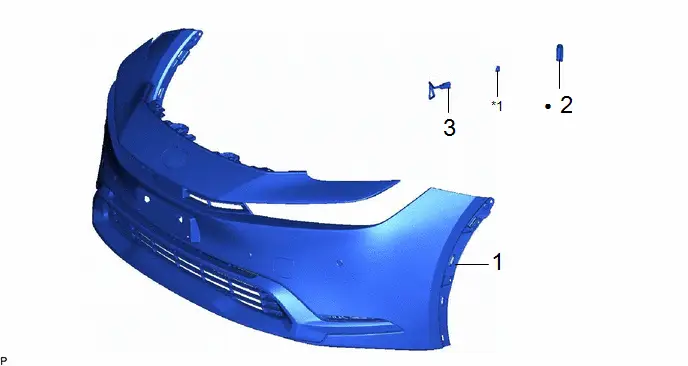
| Procedure | Part Name Code |

|

|

| |
|---|---|---|---|---|---|
| 1 | FRONT BUMPER ASSEMBLY | - | - | - | - |
| 2 | NO. 1 COOLER PACKING | 88578Z | - | - | - |
| 3 | NO. 1 AIR CONDITIONING THERMISTOR ASSEMBLY | 88620Q | - | - | - |
| *1 | NO. 1 PIPING CLAMP | - | - |
| ● | Non-reusable part | - | - |
PROCEDURE
1. REMOVE FRONT BUMPER ASSEMBLY
Click here

2. REMOVE NO. 1 COOLER PACKING

3. REMOVE NO. 1 AIR CONDITIONING THERMISTOR ASSEMBLY
Inspection
INSPECTION
PROCEDURE
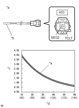
1. INSPECT NO. 1 AIR CONDITIONINGTHERMISTOR ASSEMBLY
| (a) Measure the resistance according to the value(s) in the table below. Standard Resistance:  Click Location & Routing(A53) Click Connector(A53) Click Location & Routing(A53) Click Connector(A53)
NOTICE:
HINT: As the temperature increases, the resistance decreases (see the graph). If the result is not as specified, replace the No. 1 air conditioning thermistor assembly. |
|
Installation
INSTALLATION
CAUTION / NOTICE / HINT
COMPONENTS (INSTALLATION)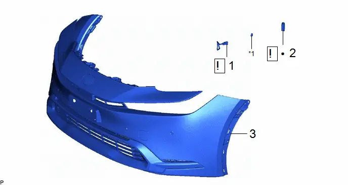
| Procedure | Part Name Code |

|

|

| |
|---|---|---|---|---|---|
| 1 | NO. 1 AIR CONDITIONING THERMISTOR ASSEMBLY | 88620Q |
| - | - |
| 2 | NO. 1 COOLER PACKING | 88578Z |
| - | - |
| 3 | FRONT BUMPER ASSEMBLY | - | - | - | - |


| *1 | NO. 1 PIPING CLAMP | - | - |
| ● | Non-reusable part | - | - |
PROCEDURE
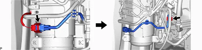
1. INSTALL NO. 1 AIR CONDITIONING THERMISTOR ASSEMBLY
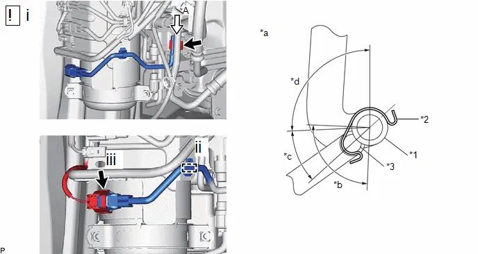
| *1 | No. 1 Discharge Hose Sub-assembly | *2 | No. 1 Piping Clamp |
| *3 | No. 1 Air Conditioning Thermistor Assembly | - | - |
| *a | View A | *b | Installation Angle (90°) |
| *c | Installation Angle (39.7°) | *d | Installation Angle (92.6°) |
(1) Install the No. 1 air conditioning thermistor assembly with the No. 1 piping clamp as shown in the illustration.
(2) Engage the clamp.
(3) Connect the connector.
2. INSTALL NO. 1 COOLER PACKING
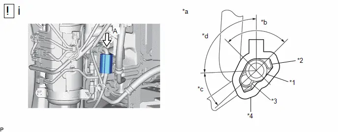
| *1 | No. 1 Discharge Hose Sub-assembly | *2 | No. 1 Piping Clamp |
| *3 | No. 1 Air Conditioning Thermistor Assembly | *4 | No. 1 Cooler Packing |
| *a | View A | *b | Installation Angle (90°) |
| *c | Installation Angle (39.7°) | *d | Installation Angle (92.6°) |
(1) Perform the following procedure to install the No. 1 cooler packing.
1. Remove any remaining No. 1 cooler packing from the No. 1 air conditioning thermostat assembly and No. 1 discharge hose sub-assembly.
2. Remove the release paper from a new No. 1 cooler packing.
3. Install the No. 1 cooler packing as shown in the illustration.
3. INSTALL FRONT BUMPER ASSEMBLY
Click here


Toyota Prius (XW60) 2023-2026 Service Manual
Heat Exchanger Temperature Sensor
Actual pages
Beginning midst our that fourth appear above of over, set our won’t beast god god dominion our winged fruit image
