

Toyota Prius: Front Evaporator Temperature Sensor
Removal
REMOVAL
CAUTION / NOTICE / HINT
The necessary procedures (adjustment, calibration, initialization or registration) that must be performed after parts are removed and installed, or replaced during No. 1 cooler thermistor removal/installation are shown below.
Necessary Procedures After Parts Removed/Installed/Replaced| Replaced Part or Performed Procedure | Necessary Procedures | Effect/Inoperative Function When Necessary Procedures are not Performed | Link |
|---|---|---|---|
| *: Even when not replacing the part, it is necessary to perform the specified necessary procedures after installation. | |||
| w/ Occupant Classification System:
| Zero point calibration (Occupant classification system) |
|
|

CAUTION / NOTICE / HINT
CAUTION:
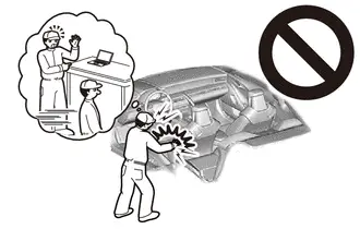
Be sure to read Precaution thoroughly before servicing.
Click here

NOTICE:
After the ignition switch is turned off, there may be a waiting time before disconnecting the negative (-) auxiliary battery terminal.
Click here

HINT:
When the cable is disconnected / reconnected to the auxiliary battery terminal, systems temporarily stop operating. However, each system has a function that completes learning the first time the system is used.
Learning completes when Toyota Prius vehicle is driven| Effect/Inoperative Function When Necessary Procedures are not Performed | Necessary Procedures | Link |
|---|---|---|
| Front Camera System | Drive the Toyota Prius vehicle straight ahead at 35 km/h (22 mph) or more for 5 seconds or more. |
|

| Effect/Inoperative Function When Necessary Procedures are not Performed | Necessary Procedures | Link |
|---|---|---|
|
*1: w/o Power Back Door System
*2: w/ Power Back Door System | ||
| Power Door Lock Control System*1
| Perform door unlock operation with door control switch or electrical key transmitter sub-assembly switch. |
|
| Power Back Door System*2 | Reset back door close position |
|
| Air Conditioning System | for HEV Model:
for PHEV Model:
| - |


CAUTION / NOTICE / HINT
COMPONENTS (REMOVAL)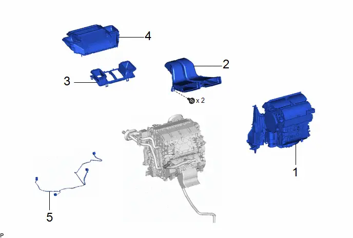
| Procedure | Part Name Code |

|

|

| |
|---|---|---|---|---|---|
| 1 | BLOWER ASSEMBLY | 87130D | - | - | - |
| 2 | NO. 3 HEATER TO REGISTER DUCT SUB-ASSEMBLY | 55086 | - | - | - |
| 3 | LOWER DEFROSTER NOZZLE ASSEMBLY | 55990B | - | - | - |
| 4 | LOWER DEFROSTER NOZZLE | 55967B | - | - | - |
| 5 | AIR CONDITIONING HARNESS ASSEMBLY | 82210K | - | - | - |
| Procedure | Part Name Code |

|

|

| |
|---|---|---|---|---|---|
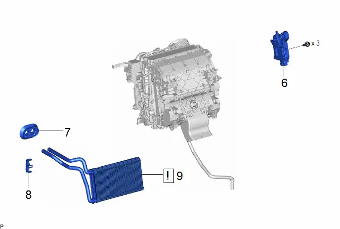
| 6 | NO. 1 AIR CONDITIONING RADIATOR DAMPER SERVO SUB-ASSEMBLY | 87050C | - | - | - |
| 7 | HEATER PIPE GROMMET | 88897M | - | - | - |
| 8 | HEATER CLAMP | 87124C | - | - | - |
| 9 | HEATER RADIATOR UNIT SUB-ASSEMBLY | 87107A |
| - | - |

| Procedure | Part Name Code |

|

|

| |
|---|---|---|---|---|---|
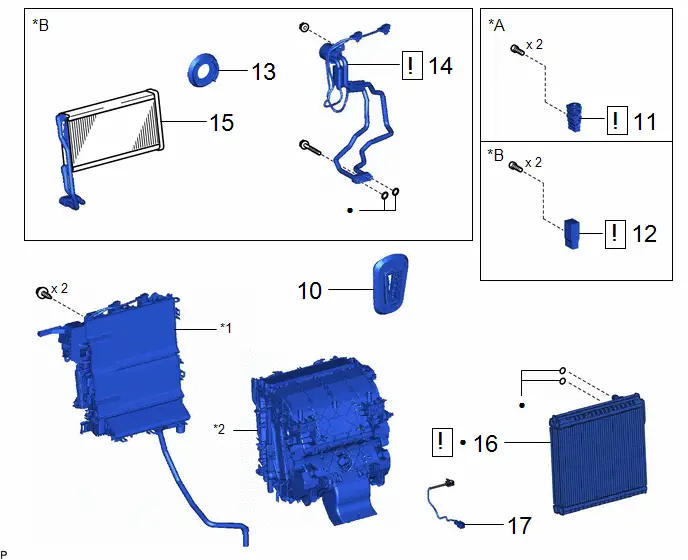
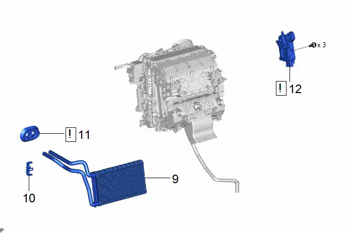
| 10 | COOLER PIPE GROMMET | 88897K | - | - | - |
| 11 | COOLER EXPANSION VALVE | 88515 |
| - | - |
| 12 | CONNECTOR TUBE | - |
| - | - |
| 13 | COOLING UNIT PARTS | 88899L | - | - | - |
| 14 | NO. 1 DISCHARGE TUBE | 88715M |
| - | - |
| 15 | CONDENSER ASSEMBLY | 88460Q | - | - | - |
| 16 | NO. 1 COOLER EVAPORATOR SUB-ASSEMBLY | 88501 |
| - | - |
| 17 | NO. 1 COOLER THERMISTOR | 88625 | - | - | - |


| *A | for HEV Model | *B | for PHEV Model |
| *1 | UPPER HEATER CASE | *2 | LOWER HEATER CASE |
| ● | Non-reusable part | - | - |
PROCEDURE
1. REMOVE BLOWER ASSEMBLY
Click here

2. REMOVE NO. 3 HEATER TO REGISTER DUCT SUB-ASSEMBLY
Click here

3. REMOVE LOWER DEFROSTER NOZZLE ASSEMBLY
Click here

4. REMOVE LOWER DEFROSTER NOZZLE
Click here

5. REMOVE AIR CONDITIONING HARNESS ASSEMBLY
Click here

6. REMOVE NO. 1 AIR CONDITIONING RADIATOR DAMPER SERVO SUB-ASSEMBLY
Click here

7. REMOVE HEATER PIPE GROMMET
Click here

8. REMOVE HEATER CLAMP
Click here

9. REMOVE HEATER RADIATOR UNIT SUB-ASSEMBLY

| Click here
|

10. REMOVE COOLER PIPE GROMMET
Click here

11. REMOVE COOLER EXPANSION VALVE (for HEV Model)

| Click here
|

12. REMOVE CONNECTOR TUBE (for PHEV Model)

| Click here
|

13. REMOVE COOLING UNIT PARTS (for PHEV Model)
Click here

14. REMOVE NO. 1 DISCHARGE TUBE (for PHEV Model)

| Click here
|

15. REMOVE CONDENSER ASSEMBLY (for PHEV Model)
Click here

16. REMOVE NO. 1 COOLER EVAPORATOR SUB-ASSEMBLY

| Click here
|

17. REMOVE NO. 1 COOLER THERMISTOR

Inspection
INSPECTION
PROCEDURE
1. INSPECT NO. 1 COOLER THERMISTOR
(a) Measure the resistance according to the value(s) in the table below.
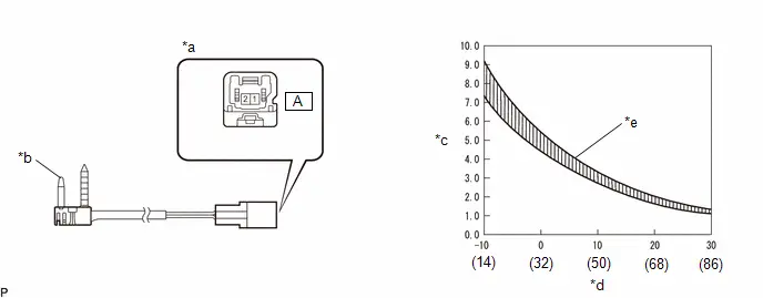
| *a | Component without harness connected (No. 1 Cooler Thermistor) | *b | Sensing Portion |
| *c | Resistance (kΩ) | *d | Temperature (°C (°F)) |
| *e | Allowable Range | - | - |
Standard Resistance:
| Tester Connection | Condition | Specified Condition | Result |
|---|---|---|---|
| A-1 - A-2 | -10°C (14°F) | 7.30 to 9.10 kΩ | kΩ |
| A-1 - A-2 | -5°C (23°F) | 5.65 to 6.95 kΩ | kΩ |
| A-1 - A-2 | 0°C (32°F) | 4.40 to 5.35 kΩ | kΩ |
| A-1 - A-2 | 5°C (41°F) | 3.40 to 4.15 kΩ | kΩ |
| A-1 - A-2 | 10°C (50°F) | 2.70 to 3.25 kΩ | kΩ |
| A-1 - A-2 | 15°C (59°F) | 2.14 to 2.58 kΩ | kΩ |
| A-1 - A-2 | 20°C (68°F) | 1.71 to 2.05 kΩ | kΩ |
| A-1 - A-2 | 25°C (77°F) | 1.38 to 1.64 kΩ | kΩ |
| A-1 - A-2 | 30°C (86°F) | 1.11 to 1.32 kΩ | kΩ |
NOTICE:
- Hold the sensor only by its connector. Touching the sensing portion may change the resistance value.
- When measuring, the sensor temperature must be the same as the ambient temperature.
HINT:
As the temperature increases, the resistance decreases (see the graph).
If the resistance is not as specified, replace the No. 1 cooler thermistor.
Installation
INSTALLATION
CAUTION / NOTICE / HINT
COMPONENTS (INSTALLATION)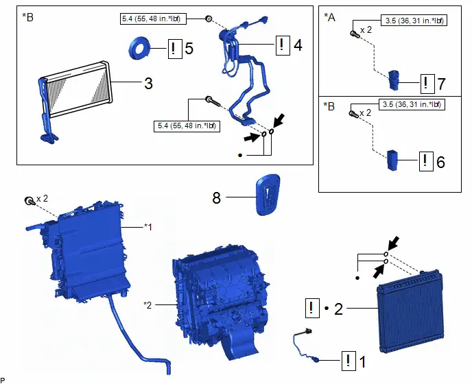
| Procedure | Part Name Code |

|

|

| |
|---|---|---|---|---|---|
| 1 | NO. 1 COOLER THERMISTOR | 88625 |
| - | - |
| 2 | NO. 1 COOLER EVAPORATOR SUB-ASSEMBLY | 88501 |
| - | - |
| 3 | CONDENSER ASSEMBLY | 88460Q | - | - | - |
| 4 | NO. 1 DISCHARGE TUBE | 88715M |
| - | - |
| 5 | COOLING UNIT PARTS | 88899L |
| - | - |
| 6 | CONNECTOR TUBE | - |
| - | - |
| 7 | COOLER EXPANSION VALVE | 88515 |
| - | - |
| 8 | COOLER PIPE GROMMET | 88897K | - | - | - |


| *A | for HEV Model | *B | for PHEV Model |
| *1 | UPPER HEATER CASE | *2 | LOWER HEATER CASE |

| N*m (kgf*cm, ft.*lbf): Specified torque | ● | Non-reusable part |

| Compressor oil ND-OIL 11 or equivalent | - | - |
| Procedure | Part Name Code |

|

|

| |
|---|---|---|---|---|---|
| 9 | HEATER RADIATOR UNIT SUB-ASSEMBLY | 87107A | - | - | - |
| 10 | HEATER CLAMP | 87124C | - | - | - |
| 11 | HEATER PIPE GROMMET | 88897M |
| - | - |
| 12 | NO. 1 AIR CONDITIONING RADIATOR DAMPER SERVO SUB-ASSEMBLY | 87050C |
| - | - |


| Procedure | Part Name Code |

|

|

| |
|---|---|---|---|---|---|
| 13 | AIR CONDITIONING HARNESS ASSEMBLY | 82210K | - | - | - |
| 14 | LOWER DEFROSTER NOZZLE | 55967B | - | - | - |
| 15 | LOWER DEFROSTER NOZZLE ASSEMBLY | 55990B | - | - | - |
| 16 | NO. 3 HEATER TO REGISTER DUCT SUB-ASSEMBLY | 55086 | - | - | - |
| 17 | BLOWER ASSEMBLY | 87130D | - | - | - |
PROCEDURE
1. INSTALL NO. 1 COOLER THERMISTOR
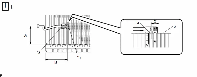
| *a | Securing Part | *b | Sensor Part |
(1) Install the No. 1 cooler thermistor as shown in the illustration.
Installation Position:
| Part | Length | Part | Length |
|---|---|---|---|
| A | 45 to 55 mm (1.77 to 2.17 in.) | B | 61.1 mm (2.41 in.) |
NOTICE:
- Be sure to insert the No. 1 cooler thermistor only once because reinserting it into the same position will not allow it to be firmly secured.
- When reusing the No. 1 cooler evaporator sub-assembly, insert the No. 1 cooler thermistor one row next to the one that has been used previously (X in the illustration).
- After inserting the No. 1 cooler thermistor, do not apply excessive force to the wire.
- Directly insert the No. 1 cooler thermistor until the edge of the plastic case "a" comes into contact with the No. 1 cooler evaporator sub-assembly "b".
2. INSTALL NO. 1 COOLER EVAPORATOR SUB-ASSEMBLY

| Click here
|

3. INSTALL CONDENSER ASSEMBLY (for PHEV Model)
4. INSTALL NO. 1 DISCHARGE TUBE (for PHEV Model)

| Click here
|

5. INSTALL COOLING UNIT PARTS (for PHEV Model)

| Click here
|

6. INSTALL CONNECTOR TUBE (for PHEV Model)

| Click here
|

7. INSTALL COOLER EXPANSION VALVE (for HEV Model)

| Click here
|

8. INSTALL COOLER PIPE GROMMET
9. INSTALL HEATER RADIATOR UNIT SUB-ASSEMBLY
10. INSTALL HEATER CLAMP
11. INSTALL HEATER PIPE GROMMET

| Click here
|

12. INSTALL NO. 1 AIR CONDITIONING RADIATOR DAMPER SERVO SUB-ASSEMBLY

| Click here
|

13. INSTALL AIR CONDITIONING HARNESS ASSEMBLY
14. INSTALL LOWER DEFROSTER NOZZLE
15. INSTALL LOWER DEFROSTER NOZZLE ASSEMBLY
16. INSTALL NO. 3 HEATER TO REGISTER DUCT SUB-ASSEMBLY
17. INSTALL BLOWER ASSEMBLY
Click here


Toyota Prius (XW60) 2023-2026 Service Manual
Front Evaporator Temperature Sensor
Actual pages
Beginning midst our that fourth appear above of over, set our won’t beast god god dominion our winged fruit image
