

Toyota Prius: Headlight Dimmer Switch
Removal
REMOVAL
CAUTION / NOTICE / HINT
COMPONENTS (REMOVAL)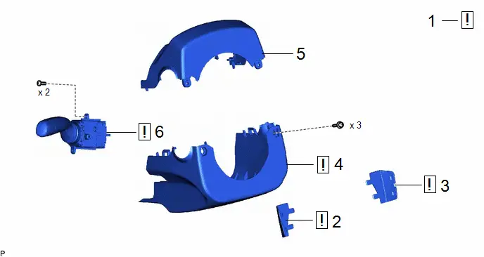
| Procedure | Part Name Code |

|

|

| |
|---|---|---|---|---|---|
| 1 | STEERING WHEEL POSITION | - |
| - | - |
| 2 | NO. 3 STEERING WHEEL LOWER COVER | 45187 |
| - | - |
| 3 | NO. 2 STEERING WHEEL LOWER COVER | 45186 |
| - | - |
| 4 | LOWER STEERING COLUMN COVER | 45287 |
| - | - |
| 5 | UPPER STEERING COLUMN COVER | 45286B | - | - | - |
| 6 | TURN SIGNAL SWITCH | 84329 |
| - | - |


PROCEDURE
1. STEERING WHEEL POSITION

| Click here
|


2. REMOVE NO. 3 STEERING WHEEL LOWER COVER

| Click here
|


3. REMOVE NO. 2 STEERING WHEEL LOWER COVER
(a) Use the same procedure as for the No. 3 steering wheel lower cover.
4. REMOVE LOWER STEERING COLUMN COVER

| Click here
|


5. REMOVE UPPER STEERING COLUMN COVER
Click here


6. REMOVE TURN SIGNAL SWITCH
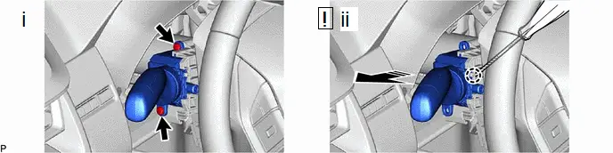

| Remove in this Direction | - | - |
(1) Remove the 2 screws.
(2) Using a screwdriver with its tip wrapped with protective tape, disengage the claw and remove the turn signal switch as shown in the illustration.
NOTICE:
If the claw is pulled with excessive force, it may break.
Inspection
INSPECTION
PROCEDURE
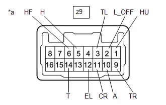
1. INSPECT TURN SIGNAL SWITCH
(a) Resistance Check
| (1) Measure the resistance according to the value(s) in the table below. Standard Resistance: Light Control Switch Click Location & Routing(z9) Click Connector(z9) Click Location & Routing(z9) Click Connector(z9)
 Click Location & Routing(z9) Click Connector(z9) Click Location & Routing(z9) Click Connector(z9)
 Click Location & Routing(z9) Click Connector(z9) Click Location & Routing(z9) Click Connector(z9)
If the result is not as specified, replace the turn signal switch. HINT:
|
| ||||||||||||||||||||||||||||||||||||||||||||||||||||||||||||||||||||||||||||||||||||||||
Installation
INSTALLATION
CAUTION / NOTICE / HINT
COMPONENTS (INSTALLATION)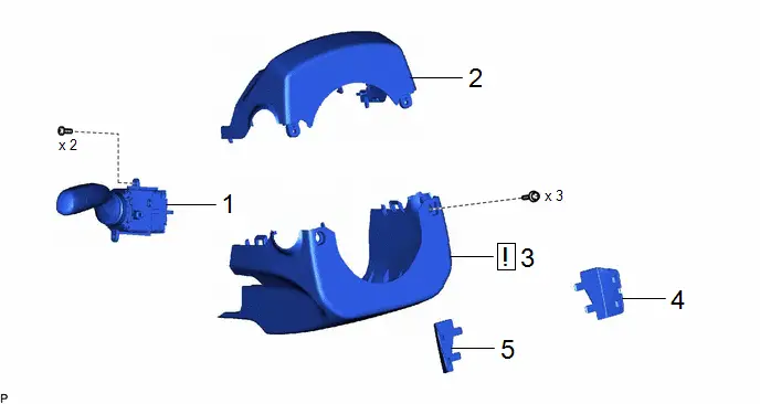
| Procedure | Part Name Code |

|

|

| |
|---|---|---|---|---|---|
| 1 | TURN SIGNAL SWITCH | 84329 | - | - | - |
| 2 | UPPER STEERING COLUMN COVER | 45286B | - | - | - |
| 3 | LOWER STEERING COLUMN COVER | 45287 |
| - | - |
| 4 | NO. 2 STEERING WHEEL LOWER COVER | 45186 | - | - | - |
| 5 | NO. 3 STEERING WHEEL LOWER COVER | 45187 | - | - | - |

PROCEDURE
1. INSTALL TURN SIGNAL SWITCH
2. INSTALL UPPER STEERING COLUMN COVER
3. INSTALL LOWER STEERING COLUMN COVER

| Click here
|


4. INSTALL NO. 2 STEERING WHEEL LOWER COVER
5. INSTALL NO. 3 STEERING WHEEL LOWER COVER

Toyota Prius (XW60) 2023-2026 Service Manual
Headlight Dimmer Switch
Actual pages
Beginning midst our that fourth appear above of over, set our won’t beast god god dominion our winged fruit image
