

Toyota Prius: Headlight Assembly
Precaution
PRECAUTION
NOTICE:
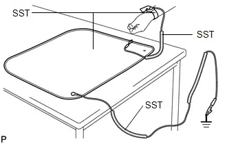
When disassembling the headlight assembly, use static electricity countermeasures SST (desktop anti-static mat set) and observe all precautions to prevent damage to the system by electrostatic discharge (ESD).
STATIC ELECTRICITY COUNTERMEASURES SST
SST: Desktop anti-static mat set (09890-47010)
-
Wristband
SST:
09891-04020
-
Wristband connection wire (No. 1 grounding wire)
SST:
09891-04030
-
Anti-static mat
SST:
09891-04010
-
Ground connection wire (No. 2 grounding wire)
SST:
09891-04040
PRECAUTIONS DURING REPLACEMENT
(a) Precautions during procedures:
(1) Before performing any procedures, touch an unpainted metal part or ground bolt of the Toyota Prius vehicle to eliminate any static electricity.
(2) To prevent damage to electrical equipment, disconnect the battery power supply before installing and removing electrical equipment.
(3) Never touch the electronic parts of a printed wire board or the pins of an integrated circuit.
(4) When performing procedures, do not allow clothing to come near or contact parts.

(b) Wear SST (wristband) firmly on your wrist.
SST:
09891-04020
(c) Connect SST (No. 2 grounding wire) and SST (anti-static mat) to an appropriate grounding point in the workspace and on the work table.
SST:
09891-04040
09891-04010
HINT:
When working inside the Toyota Prius vehicle:
Connect SST (No. 2 grounding wire) to an unpainted metal part or a ground bolt, etc.
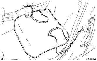
(d) Connect SST (No. 1 grounding wire), SST (wristband) and SST (anti-static mat).
SST:
09891-04030
(e) Always place the headlight assembly and its components on SST (anti-static mat).
Removal
REMOVAL
CAUTION / NOTICE / HINT
The necessary procedures (adjustment, calibration, initialization or registration) that must be performed after parts are removed and installed, or replaced during headlight assembly removal/installation are shown below.
Necessary Procedures After Parts Removed/Installed/Replaced| Replaced Part or Performed Procedure | Necessary Procedures | Effect/Inoperative Function When Necessary Procedures are not Performed | Link |
|---|---|---|---|
| *1: Even when not replacing the part, it is necessary to perform the specified necessary procedures after installation. | |||
| Front bumper assembly*1 | Front television camera view adjustment | Panoramic View Monitor System |
|
| Advanced Park |
| ||
| Replacement or removal and installation of 2 or more parts:
| Television camera view adjustment | Panoramic View Monitor System |
|


CAUTION / NOTICE / HINT
HINT:
- Use the same procedure for the RH side and LH side.
- The following procedure is for the LH side.
-
w/ Front Side Radar:
If the headlight assembly is damaged or deformed due to an accident, contact, etc., and repairs have been made to the area of the body to which the headlight assembly is installed, it is necessary to perform front side radar sensor adjustment.
for Driving Adjustment: Click here

for Target Adjustment (Triangle Target): Click here

CAUTION / NOTICE / HINT
COMPONENTS (REMOVAL)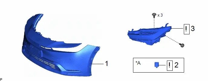
| Procedure | Part Name Code |

|

|

| |
|---|---|---|---|---|---|
| 1 | FRONT BUMPER ASSEMBLY | - | - | - | - |
| 2 | FRONT SIDE RADAR SENSOR | 882B1 |
| - | - |
| 3 | HEADLIGHT ASSEMBLY | - |
| - | - |


| *A | w/ Front Side Radar | - | - |
PROCEDURE
1. REMOVE FRONT BUMPER ASSEMBLY
Click here

2. REMOVE FRONT SIDE RADAR SENSOR (w/ Front Side Radar)

| Click here
|


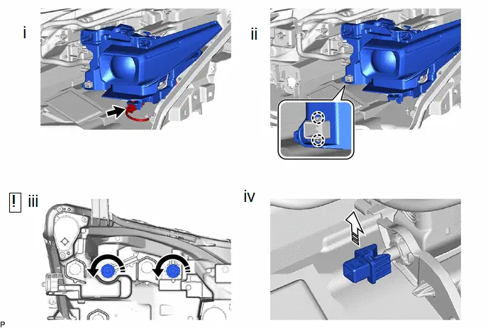
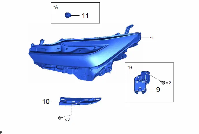
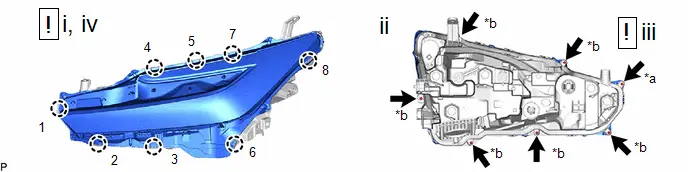
3. REMOVE HEADLIGHT ASSEMBLY
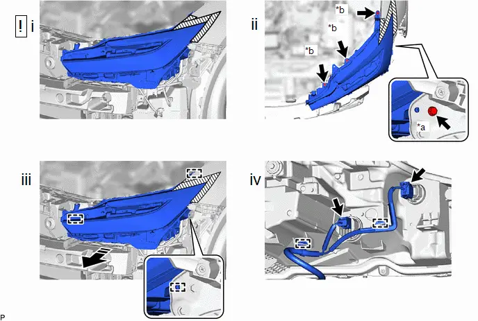
| *a | Bolt | *b | Screw |

| Protective Tape |

| Disengage in this Direction |
(1) Apply protective tape around the headlight assembly as shown in the illustration.
(2) Remove the bolt and 3 screws.
(3) Disengage the 3 guides as shown in the illustration.
(4) Disconnect the 2 connectors and disengage the 2 clamps to remove the headlight assembly.
Disassembly
DISASSEMBLY
CAUTION / NOTICE / HINT
HINT:
- Use the same procedure for the RH side and LH side.
- The following procedure is for the LH side.
CAUTION / NOTICE / HINT
COMPONENTS (DISASSEMBLY)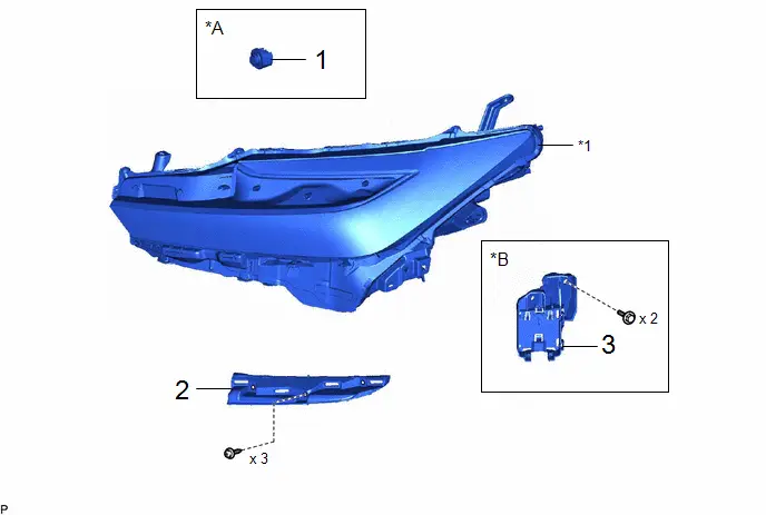
| Procedure | Part Name Code |

|

|

| |
|---|---|---|---|---|---|
| 1 | HEADLIGHT FRONT TURN SIGNAL LED | 8113A | - | - | - |
| 2 | HEADLIGHT BRACKET | 53246B | - | - | - |
| 3 | FRONT SIDE RADAR SENSOR BRACKET | 88215C | - | - | - |
| *A | w/ Front Turn Signal LED Socket | *B | w/ Front Side Radar |
| *1 | HEADLIGHT UNIT SUB-ASSEMBLY | - | - |
| Procedure | Part Name Code |

|

|

| |
|---|---|---|---|---|---|
| 4 | HEADLIGHT LENS | 81186 |
| - | - |
| 5 | HEADLIGHT LENS GASKET | 81132B |
| - | - |
| 6 | INNER LENS ASSEMBLY | - | - | - | - |
| 7 | REFLECTOR | - | - | - | - |
| 8 | INNER ASSEMBLY | - |
| - | - |
| 9 | HEADLIGHT UNIT | 81175 |
| - | - |
| 10 | HEADLIGHT LEVELING MOTOR | 85691 | - | - | - |
| 11 | LIGHT CONTROL LED ECU | 85967D | - | - | - |


| *1 | HEADLIGHT LEVELING MOTOR WITH BRACKET | *2 | HEADLIGHT LEVELING MOTOR BRACKET |
| ● | Non-reusable part | - | - |
PROCEDURE
1. REMOVE HEADLIGHT FRONT TURN SIGNAL LED (w/ Front Turn Signal LED Socket)

2. REMOVE HEADLIGHT BRACKET

3. REMOVE FRONT SIDE RADAR SENSOR BRACKET (w/ Front Side Radar)

4. REMOVE HEADLIGHT LENS

| NOTICE:
|
SST: 09890-47010
09891-04010
09891-04020
09891-04030
09891-04040

| *a | "TORX" screw | *b | Screw |
(1) Remove the 6 screws.
(2) Using a T20H "TORX" driver, remove the "TORX" screw.
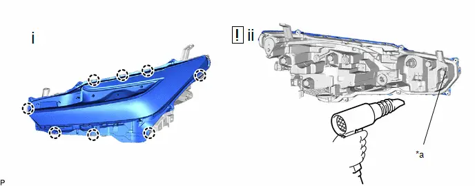
| *a | Separation Starting Point | - | - |
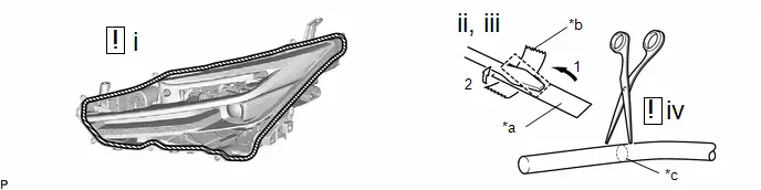
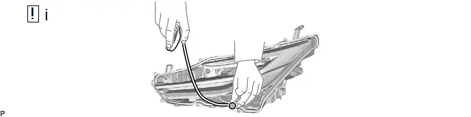
(1) Disengage the 8 claws.
(2) Using a dryer, warm the headlight lens gasket from the backside of the headlight unit assembly at the separation starting point of the headlight lens and headlight housing.
NOTICE:
If the headlight unit assembly is heated unevenly, it will deform or melt.

| Headlight Lens |

| Separation Starting Point |

| Headlight Lens Gasket |

| Headlight Housing |
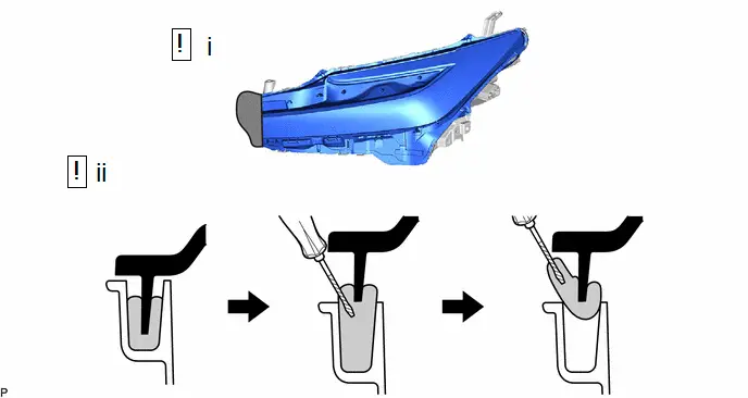
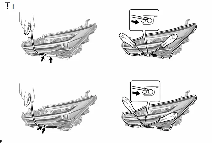
(1) Insert a finger between the headlight lens and headlight housing and lift up the headlight lens.
HINT:
- With all of the claws disengaged, lift up the headlight lens.
- When the headlight lens is lifted up, the claws may re-engage.
(2) Using a screwdriver with its tip wrapped with protective tape, pull out the headlight lens gasket through the opening.
NOTICE:
Do not damage the groove in the headlight housing or the headlight lens.
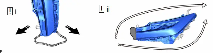

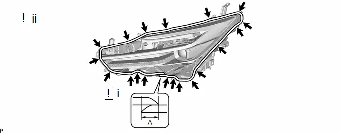
| Separation Starting Point |

| Headlight Lens Gasket |

| Pull out in this Direction |

| Remove in this Direction |
(1) Pull out the headlight lens gasket as shown in the illustration to remove the headlight lens.
HINT:
- With all of the claws disengaged, lift up the headlight lens.
- When the headlight lens is lifted up, the claws may re-engage.
- Before lifting up the headlight lens, check that the surrounding claws have not re-engaged.
- If the headlight lens gasket is disconnected while being pulled out, lift up the headlight lens and pull the headlight lens gasket again.
(2) Remove the headlight lens from the headlight housing from the separation starting point toward the outside of the Toyota Prius vehicle as shown in the illustration.
5. REMOVE HEADLIGHT LENS GASKET

| NOTICE:
|
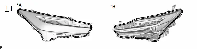
| *A | Headlight Lens Side | *B | Headlight Housing Side |

| Headlight Lens Gasket | - | - |
(1) Remove the remaining headlight lens gasket from the headlight lens and headlight housing.
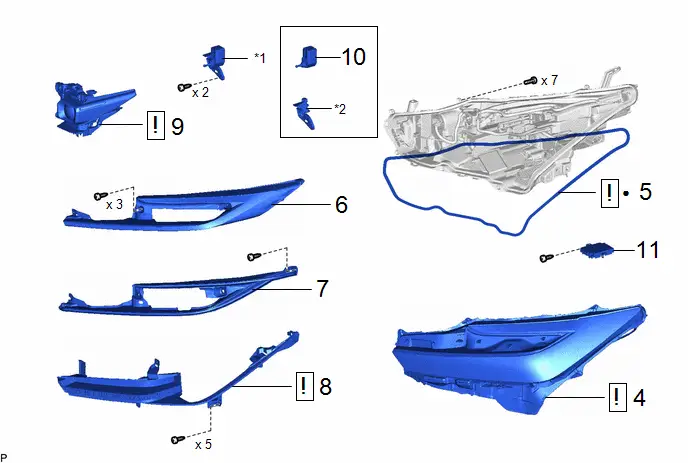
6. REMOVE INNER LENS ASSEMBLY

7. REMOVE REFLECTOR

8. REMOVE INNER ASSEMBLY

| Place Hand Here |

| Remove in this Direction |
(1) Remove the 5 screws.
(2) Disengage the clip to remove the inner assembly as shown in the illustration.
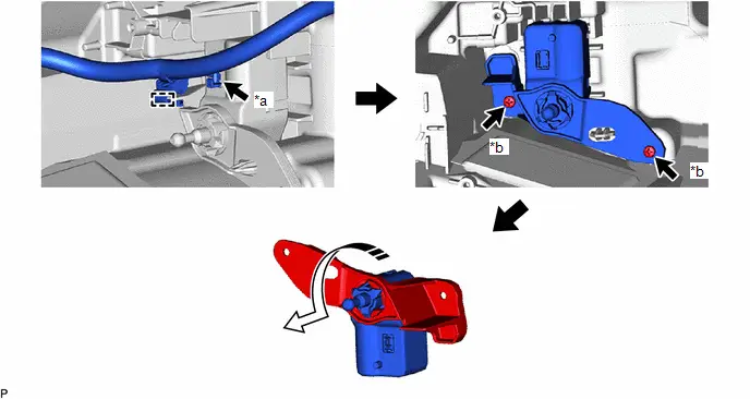
9. REMOVE HEADLIGHT UNIT

| NOTICE:
|
SST: 09890-47010
09891-04010
09891-04020
09891-04030
09891-04040
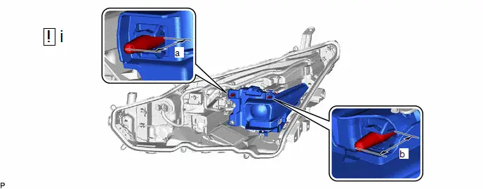
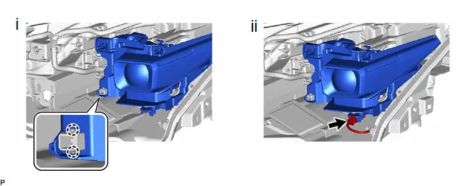
(1) Using a vernier caliper, record the dimensions of a and b shown in the illustration.

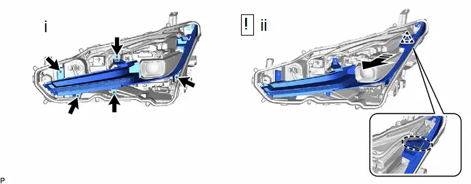
| Turn in this Direction |

| Remove in this Direction |
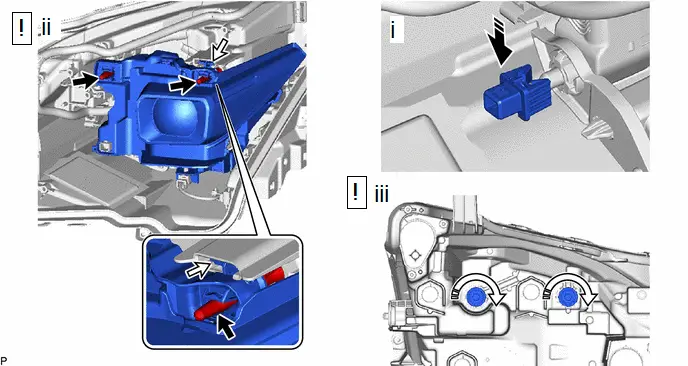
(1) Disconnect the connector.
(2) Disengage the 2 claws.
(3) While holding the headlight unit assembly by hand, turn the aiming screws as shown in the illustration until the aiming screws are separated from the headlight unit.
(4) Remove the pivot collar as shown in the illustration.
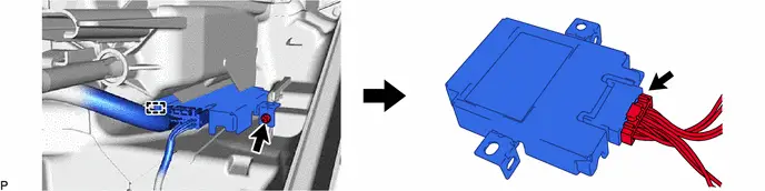
10. REMOVE HEADLIGHT LEVELING MOTOR
| *a | Connector | *b | Screw |

| Remove in this Direction | - | - |
11. REMOVE LIGHT CONTROL LED ECU
Inspection
INSPECTION
PROCEDURE
1. INSPECT HEADLIGHT HOUSING LH (w/ Front Turn Signal LED Socket)
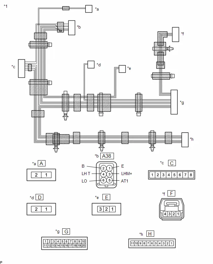
(a) Measure the resistance according to the value(s) in the table below.

| *1 | Headlight Housing LH (Headlight Cord) | - | - |
| *a | Component without harness connected (to No. 1 Headlight Clearance LED LH) | *b | Component without harness connected (to Wire Harness) |
| *c | Component without harness connected (to Headlight Leveling Motor LH) | *d | Component without harness connected (to Headlight Unit LH) |
| *e | Component without harness connected (to Light Control ECU) | *f | Component without harness connected (to Headlight Turn Signal LED Unit) |
(1) Inspect the clearance light/daytime running light circuit.
Standard Resistance:
| Tester Connection | Condition | Specified Condition | Result |
|---|---|---|---|
| A-1 - F-5 | Always | Below 1 Ω | Ω |
| A-2 - E-6 | Always | Below 1 Ω | Ω |
| E-7 - F-1 | Always | Below 1 Ω | Ω |
| E-12 - F-8 | Always | Below 1 Ω | Ω |
| E-13 - F-9 | Always | Below 1 Ω | Ω |
| E-14 - F-2 | Always | Below 1 Ω | Ω |
| E-17 - F-4 | Always | Below 1 Ω | Ω |
If the result is not as specified, replace the headlight housing LH (headlight cord).
(2) Inspect the Lo/Hi beam circuit.
Standard Resistance:
| Tester Connection | Condition | Specified Condition | Result |
|---|---|---|---|
| D-1 - E-16 | Always | Below 1 Ω | Ω |
| D-2 - E-10 | Always | Below 1 Ω | Ω |
| D-3 - E-15 | Always | Below 1 Ω | Ω |
| D-4 - E-4 | Always | Below 1 Ω | Ω |
If the result is not as specified, replace the headlight housing LH (headlight cord).
(3) Inspect the headlight leveling motor circuit.
Standard Resistance:
 Click Location & Routing(A38) Click Connector(A38)
 | Tester Connection | Condition | Specified Condition | Result |
|---|---|---|---|
| A38-2 (B) - C-3 | Always | Below 1 Ω | Ω |
| A38-3 (LHM ) - C-2 | Always | Below 1 Ω | Ω |
| A38-4 (LH T) - C-1 | Always | Below 1 Ω | Ω |
If the result is not as specified, replace the headlight housing LH (headlight cord).
(4) Inspect the light control ECU power source circuit.
Standard Resistance:
 Click Location & Routing(A38) Click Connector(A38)
 | Tester Connection | Condition | Specified Condition | Result |
|---|---|---|---|
| A38-2 (B) - E-8 | Always | Below 1 Ω | Ω |
| A38-5 (AT1) - E-19 | Always | Below 1 Ω | Ω |
| A38-6 (LO) - E-11 | Always | Below 1 Ω | Ω |
If the result is not as specified, replace the headlight housing LH (headlight cord).
2. INSPECT HEADLIGHT HOUSING LH (w/o Front Turn Signal LED Socket)
(a) Measure the resistance according to the value(s) in the table below.
| *1 | Headlight Housing LH (Headlight Cord) | - | - |
| *a | Component without harness connected (to No. 1 Headlight Clearance LED LH) | *b | Component without harness connected (to Wire Harness) |
| *c | Component without harness connected (to Headlight Turn Signal LED Unit) | *d | Component without harness connected (to No. 2 Headlight Clearance LED LH) |
| *e | Component without harness connected (to Headlight Leveling Motor LH) | *f | Component without harness connected (to Headlight Unit LH) |
| *g | Component without harness connected (to Light Control ECU) | *h | Component without harness connected (to No. 3 Headlight Clearance LED LH) |
(1) Inspect the clearance light/daytime running light circuit.
Standard Resistance:
| Tester Connection | Condition | Specified Condition | Result |
|---|---|---|---|
| A-1 - H-7 | Always | Below 1 Ω | Ω |
| A-2 - G-6 | Always | Below 1 Ω | Ω |
| D-1 - G-20 | Always | Below 1 Ω | Ω |
| D-2 - G-3 | Always | Below 1 Ω | Ω |
| G-7 - H-10 | Always | Below 1 Ω | Ω |
| G-12 - H-1 | Always | Below 1 Ω | Ω |
| G-13 - H-2 | Always | Below 1 Ω | Ω |
| G-14 - H-11 | Always | Below 1 Ω | Ω |
| G-17 - H-8 | Always | Below 1 Ω | Ω |
If the result is not as specified, replace the headlight housing LH (headlight cord).
(2) Inspect the turn signal light circuit.
Standard Resistance:
 Click Location & Routing(A38) Click Connector(A38)
 | Tester Connection | Condition | Specified Condition | Result |
|---|---|---|---|
| A38-1 (E) - C-2 | Always | Below 1 Ω | Ω |
| A38-2 (B) - C-3 | Always | Below 1 Ω | Ω |
| C-4 - H-5 | Always | Below 1 Ω | Ω |
| C-5 - H-3 | Always | Below 1 Ω | Ω |
| C-6 - H-4 | Always | Below 1 Ω | Ω |
| C-8 - H-6 | Always | Below 1 Ω | Ω |
If the result is not as specified, replace the headlight housing LH (headlight cord).
(3) Inspect the Lo/Hi beam circuit.
Standard Resistance:
| Tester Connection | Condition | Specified Condition | Result |
|---|---|---|---|
| F-1 - G-16 | Always | Below 1 Ω | Ω |
| F-2 - G-10 | Always | Below 1 Ω | Ω |
| F-3 - G-15 | Always | Below 1 Ω | Ω |
| F-4 - G-4 | Always | Below 1 Ω | Ω |
If the result is not as specified, replace the headlight housing LH (headlight cord).
(4) Inspect the headlight leveling motor circuit.
Standard Resistance:
 Click Location & Routing(A38) Click Connector(A38)
 | Tester Connection | Condition | Specified Condition | Result |
|---|---|---|---|
| A38-2 (B) - E-3 | Always | Below 1 Ω | Ω |
| A38-3 (LHM ) - E-2 | Always | Below 1 Ω | Ω |
| A38-4 (LH T) - E-1 | Always | Below 1 Ω | Ω |
If the result is not as specified, replace the headlight housing LH (headlight cord).
(5) Inspect the light control ECU power source circuit.
Standard Resistance:
 Click Location & Routing(A38) Click Connector(A38)
 | Tester Connection | Condition | Specified Condition | Result |
|---|---|---|---|
| A38-2 (B) - G-8 | Always | Below 1 Ω | Ω |
| A38-5 (AT1) - G-19 | Always | Below 1 Ω | Ω |
| A38-6 (LO) - G-11 | Always | Below 1 Ω | Ω |
If the result is not as specified, replace the headlight housing LH (headlight cord).
3. INSPECT HEADLIGHT HOUSING RH (w/ Front Turn Signal LED Socket)
(a) Measure the resistance according to the value(s) in the table below.
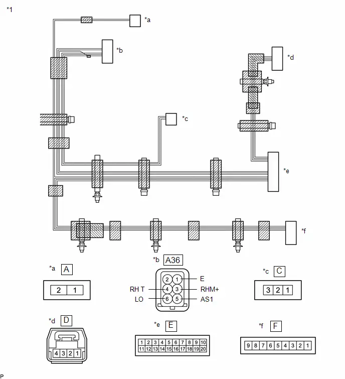
| *1 | Headlight Housing RH (Headlight Cord) | - | - |
| *a | Component without harness connected (to No. 1 Headlight Clearance LED RH) | *b | Component without harness connected (to Wire Harness) |
| *c | Component without harness connected (to Headlight Leveling Motor RH) | *d | Component without harness connected (to Headlight Unit RH) |
| *e | Component without harness connected (to Light Control ECU) | *f | Component without harness connected (to Headlight Turn Signal LED Unit) |
(1) Inspect the clearance light/daytime running light circuit.
Standard Resistance:
| Tester Connection | Condition | Specified Condition | Result |
|---|---|---|---|
| A-1 - F-5 | Always | Below 1 Ω | Ω |
| A-2 - E-6 | Always | Below 1 Ω | Ω |
| E-7 - F-1 | Always | Below 1 Ω | Ω |
| E-12 - F-8 | Always | Below 1 Ω | Ω |
| E-13 - F-9 | Always | Below 1 Ω | Ω |
| E-14 - F-2 | Always | Below 1 Ω | Ω |
| E-17 - F-4 | Always | Below 1 Ω | Ω |
If the result is not as specified, replace the headlight housing RH (headlight cord).
(2) Inspect the Lo/Hi beam circuit.
Standard Resistance:
| Tester Connection | Condition | Specified Condition | Result |
|---|---|---|---|
| D-1 - E-16 | Always | Below 1 Ω | Ω |
| D-2 - E-10 | Always | Below 1 Ω | Ω |
| D-3 - E-15 | Always | Below 1 Ω | Ω |
| D-4 - E-4 | Always | Below 1 Ω | Ω |
If the result is not as specified, replace the headlight housing RH (headlight cord).
(3) Inspect the headlight leveling motor circuit.
Standard Resistance:
 Click Location & Routing(A36) Click Connector(A36)
 | Tester Connection | Condition | Specified Condition | Result |
|---|---|---|---|
| A36-2 (B) - C-3 | Always | Below 1 Ω | Ω |
| A36-3 (RHM ) - C-2 | Always | Below 1 Ω | Ω |
| A36-4 (RH T) - C-1 | Always | Below 1 Ω | Ω |
If the result is not as specified, replace the headlight housing RH (headlight cord).
(4) Inspect the light control ECU power source circuit.
Standard Resistance:
 Click Location & Routing(A36) Click Connector(A36)
 | Tester Connection | Condition | Specified Condition | Result |
|---|---|---|---|
| A36-2 (B) - E-8 | Always | Below 1 Ω | Ω |
| A36-5 (AS1) - E-19 | Always | Below 1 Ω | Ω |
| A36-6 (LO) - E-11 | Always | Below 1 Ω | Ω |
If the result is not as specified, replace the headlight housing RH (headlight cord).
4. INSPECT HEADLIGHT HOUSING RH (w/o Front Turn Signal LED Socket)
(a) Measure the resistance according to the value(s) in the table below.

| *1 | Headlight Housing RH (Headlight Cord) | - | - |
| *a | Component without harness connected (to No. 1 Headlight Clearance LED RH) | *b | Component without harness connected (to Wire Harness) |
| *c | Component without harness connected (to Headlight Turn Signal LED Unit) | *d | Component without harness connected (to No. 2 Headlight Clearance LED RH) |
| *e | Component without harness connected (to Headlight Leveling Motor RH) | *f | Component without harness connected (to Headlight Unit RH) |
| *g | Component without harness connected (to Light Control ECU) | *h | Component without harness connected (to No. 3 Headlight Clearance LED RH) |
(1) Inspect the clearance light/daytime running light circuit.
Standard Resistance:
| Tester Connection | Condition | Specified Condition | Result |
|---|---|---|---|
| A-1 - H-4 | Always | Below 1 Ω | Ω |
| A-2 - G-6 | Always | Below 1 Ω | Ω |
| D-1 - G-20 | Always | Below 1 Ω | Ω |
| D-2 - G-3 | Always | Below 1 Ω | Ω |
| G-7 - H-1 | Always | Below 1 Ω | Ω |
| G-12 - H-10 | Always | Below 1 Ω | Ω |
| G-13 - H-11 | Always | Below 1 Ω | Ω |
| G-14 - H-2 | Always | Below 1 Ω | Ω |
| G-17 - H-5 | Always | Below 1 Ω | Ω |
If the result is not as specified, replace the headlight housing RH (headlight cord).
(2) Inspect the turn signal light circuit.
Standard Resistance:
 Click Location & Routing(A36) Click Connector(A36)
 | Tester Connection | Condition | Specified Condition | Result |
|---|---|---|---|
| A36-1 (E) - C-2 | Always | Below 1 Ω | Ω |
| A36-2 (B) - C-3 | Always | Below 1 Ω | Ω |
| C-4 - H-6 | Always | Below 1 Ω | Ω |
| C-5 - H-8 | Always | Below 1 Ω | Ω |
| C-6 - H-9 | Always | Below 1 Ω | Ω |
| C-8 - H-7 | Always | Below 1 Ω | Ω |
If the result is not as specified, replace the headlight housing RH (headlight cord).
(3) Inspect the Lo/Hi beam circuit.
Standard Resistance:
| Tester Connection | Condition | Specified Condition | Result |
|---|---|---|---|
| F-1 - G-16 | Always | Below 1 Ω | Ω |
| F-2 - G-10 | Always | Below 1 Ω | Ω |
| F-3 - G-15 | Always | Below 1 Ω | Ω |
| F-4 - G-4 | Always | Below 1 Ω | Ω |
If the result is not as specified, replace the headlight housing RH (headlight cord).
(4) Inspect the headlight leveling motor circuit.
Standard Resistance:
 Click Location & Routing(A36) Click Connector(A36)
 | Tester Connection | Condition | Specified Condition | Result |
|---|---|---|---|
| A36-2 (B) - E-3 | Always | Below 1 Ω | Ω |
| A36-3 (RHM ) - E-2 | Always | Below 1 Ω | Ω |
| A36-4 (RH T) - E-1 | Always | Below 1 Ω | Ω |
If the result is not as specified, replace the headlight housing RH (headlight cord).
(5) Inspect the light control ECU power source circuit.
Standard Resistance:
 Click Location & Routing(A36) Click Connector(A36)
 | Tester Connection | Condition | Specified Condition | Result |
|---|---|---|---|
| A36-2 (B) - G-8 | Always | Below 1 Ω | Ω |
| A36-5 (AS1) - G-19 | Always | Below 1 Ω | Ω |
| A36-6 (LO) - G-11 | Always | Below 1 Ω | Ω |
If the result is not as specified, replace the headlight housing RH (headlight cord).
Adjustment
ADJUSTMENT
CAUTION / NOTICE / HINT
HINT:
- Use the same procedure for the RH side and LH side.
- The following procedure is for the LH side.
PROCEDURE
1. PREPARE VEHICLE FOR HEADLIGHT AIM ADJUSTMENT
(a) Prepare the Toyota Prius vehicle:
- Ensure that there is no damage or deformation to the vehicle body around the headlights.
- Fill the fuel tank.
- Make sure that the engine oil is filled to the specified level.
- Make sure that the engine coolant is filled to the specified level.
- Inflate the tires to the appropriate pressure.
- Unload the trunk and Toyota Prius vehicle, ensuring that the spare tire, tools and jack are in their original positions.
- Sit a person of average weight (68 kg, 150 lb) in the driver's seat.
2. PREPARE FOR HEADLIGHT AIMING (Using a headlight aim test machine)
(a) Adjust the headlight aim in accordance with the headlight aim test machine instructions.
3. PREPARE FOR HEADLIGHT AIMING (Using a screen)
(a) Prepare the Toyota Prius vehicle:
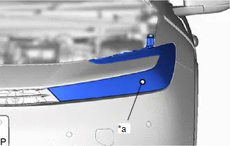
| *a | Center Mark |
- Place the Toyota Prius vehicle in a location that is dark enough to clearly observe the cutoff line. The cutoff line is a distinct line, below which light from the headlights can be observed and above which it cannot.
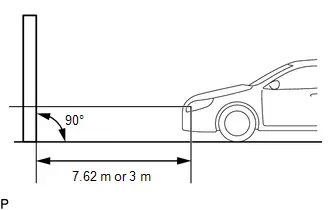
- Place the vehicle at a 90° angle to the wall.
- Create a 7.62 m (25 ft.) distance between the Toyota Prius vehicle (center marks of the headlights) and the wall.
- Make sure that the vehicle is on a level surface.
- Position the front wheels straight ahead.
- Bounce the vehicle up and down to settle the suspension.
NOTICE:
A distance of 7.62 m (25 ft.) between the Toyota Prius vehicle (center marks of the headlights) and the wall is necessary for proper aim adjustment. If sufficient space is not available, secure a distance of exactly 3 m (9.84 ft.) to allow for checking and adjustment of headlight aim. (The size of the target zone will change with the distance, so follow the instructions in the illustration.)
(b) Prepare a piece of thick white paper (approximately 2 m (6.56 ft.) (height) x 4 m (13.1 ft.) (width)) to use as a screen.
(c) Draw a vertical line down the center of the screen (V line).
(d) Set the screen as shown in the illustration.
HINT:
- Stand the screen perpendicular to the ground.
- Align the V line on the screen with the center of the Toyota Prius vehicle.
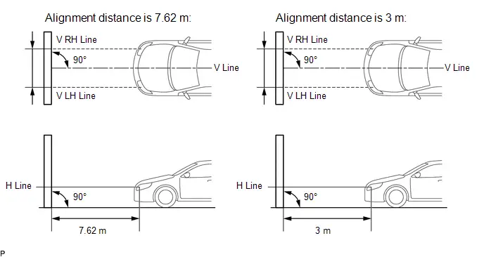
(e) Draw base lines (H, V LH, and V RH lines) on the screen as shown in the illustration.
HINT:
- The base lines differ for "low beam inspection" and "high beam inspection".
- Mark the headlight center marks on the screen.

| *a | Center Mark |
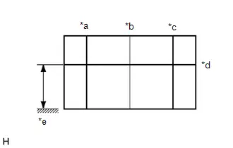
| *a | V LH Line |
| *b | V Line |
| *c | V RH Line |
| *d | H Line |
| *e | Ground |
(1) H Line (Headlight height):
Draw a horizontal line across the screen so that it passes through the center marks. The H line should be at the same height as the center marks of the headlights.
(2) V LH Line, V RH Line (Center mark position of left-hand (LH) and right-hand (RH) headlights):
Draw 2 vertical lines so that they intersect the H line at each center mark (aligned with the center marks of the headlights).
4. INSPECT HEADLIGHT AIMING
(a) Cover the headlight on the opposite side to prevent light from the headlight that is not being inspected from affecting the headlight aiming inspection.
NOTICE:
Do not keep the headlight covered for more than 3 minutes. The headlight lens is made of synthetic resin, which may melt or be damaged due to excessive heat.
HINT:
When checking the aim of the high beam, cover the low beam.
(b) Start the engine.
(c) Turn on the headlights and check the aiming of each beam.
HINT:
- Since the low beam headlight and the high beam headlight are a unit, if the aim on the low beam is correct, the high beam should also be correct. However, check both beams just to make sure.
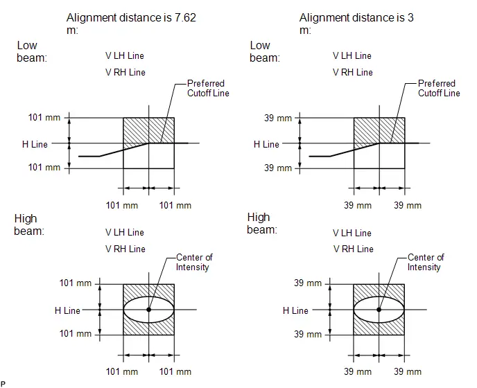
-
If the alignment distance is 7.62 m (25 ft.):
The low beam cutoff line should be between 101 mm (3.97 in.) above or below the H line as well as 101 mm (3.97 in.) left or right of the V LH or RH line (SAE J599).
-
If the alignment distance is 3 m (9.84 ft.):
The low beam cutoff line should be between 39 mm (1.56 in.) above or below the H line as well as 39 mm (1.56 in.) left or right of the V LH or RH line (SAE J599).
-
If the alignment distance is 7.62 m (25 ft.):
The high beam center of intensity should be within 101 mm (3.97 in.) above or below the H line as well as 101 mm (3.97 in.) left and right of the V LH or RH line (SAE J599).
-
If the alignment distance is 3 m (9.84 ft.):
The high beam center of intensity should be within 39 mm (1.56 in.) above or below the H line as well as 39 mm (1.56 in.) left or right of the V LH or RH line (SAE J599).
5. ADJUST HEADLIGHT AIMING
(a) Adjust the aim vertically:
(1) Adjust the aim of each headlight to the specified range by turning each aiming screw with a screwdriver.
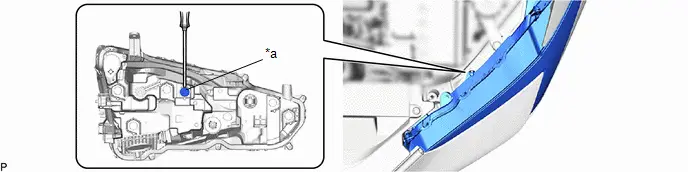
| *a | Aiming Screw | - | - |
NOTICE:
The final turn of the aiming screw should be made in the clockwise direction. If the screw is tightened excessively, loosen it and then retighten it, so that the final turn of the screw is in the clockwise direction.
HINT:
- Since the low beam headlight and the high beam headlight are a unit, if the aim on the low beam is correct, the high beam should also be correct. However, check both beams just to make sure.
- If it is not possible to correctly adjust headlight aim, check the headlight unit and headlight unit lens installation.
- Confirm the direction of rotation of the aiming screw by observing it while it is being adjusted. Due to the position of the screwdriver, the direction of rotation of the adjusting screw can be different than the direction of rotation of the screwdriver being used to adjust it.
Reassembly
REASSEMBLY
CAUTION / NOTICE / HINT
HINT:
- Use the same procedure for the RH side and LH side.
- The following procedure is for the LH side.
CAUTION / NOTICE / HINT
COMPONENTS (REASSEMBLY)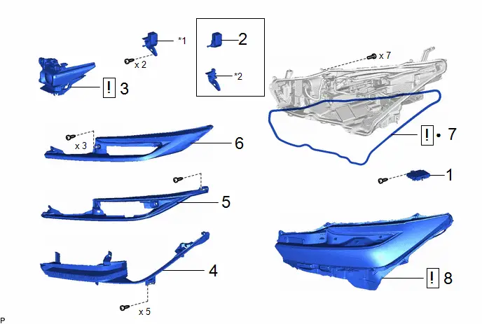
| Procedure | Part Name Code |

|

|

| |
|---|---|---|---|---|---|
| 1 | LIGHT CONTROL LED ECU | 85967D | - | - | - |
| 2 | HEADLIGHT LEVELING MOTOR | 85691 | - | - | - |
| 3 | HEADLIGHT UNIT | 81171A |
| - | - |
| 4 | INNER LENS ASSEMBLY | - | - | - | - |
| 5 | REFLECTOR | - | - | - | - |
| 6 | INNER LENS ASSEMBLY | - | - | - | - |
| 7 | HEADLIGHT LENS GASKET | 81132B |
| - | - |
| 8 | HEADLIGHT LENS | 81186 |
| - | - |


| *1 | HEADLIGHT LEVELING MOTOR WITH BRACKET | *2 | HEADLIGHT LEVELING MOTOR BRACKET |
| ● | Non-reusable part | - | - |
| Procedure | Part Name Code |

|

|

| |
|---|---|---|---|---|---|
| 9 | FRONT SIDE RADAR SENSOR BRACKET | 88215C | - | - | - |
| 10 | HEADLIGHT BRACKET | 53246B | - | - | - |
| 11 | HEADLIGHT FRONT TURN SIGNAL LED | 8113A | - | - | - |
| *A | w/ Front Turn Signal LED Socket | *B | w/ Front Side Radar |
| *1 | HEADLIGHT UNIT SUB-ASSEMBLY | - | - |
PROCEDURE
1. INSTALL LIGHT CONTROL LED ECU
2. INSTALL HEADLIGHT LEVELING MOTOR
3. INSTALL HEADLIGHT UNIT

| NOTICE:
|
SST: 09890-47010
09891-04010
09891-04020
09891-04030
09891-04040

| Adjustment Aiming Screws |

| Adjustment Aiming Rail |

| Install in this Direction |

| Turn in this Direction |
(1) Install the pivot collar as shown in the illustration.
(2) Temporarily install the headlight unit assembly to the 2 adjustment aiming rails and 2 adjustment aiming screws as shown in the illustration.
(3) Hold the headlight unit assembly LH with one hand to prevent it from tipping over, alternately tighten the 2 adjustment aiming screws in the direction indicated by the arrow shown in the illustration, and align the dimensions with the recorded values at removal.
(1) Engage the 2 claws to connect the pivot collar.
(2) Connect the connector to install the headlight unit.
4. INSTALL INNER ASSEMBLY
5. INSTALL REFLECTOR
6. INSTALL INNER LENS ASSEMBLY
7. INSTALL HEADLIGHT LENS GASKET

| NOTICE:
|
| *a | Release Paper | *b | Tape |
| *c | 90° | - | - |

| Cleaning Area | - | - |
(1) Clean the installation groove of the headlight lens.
(2) Partially remove the release paper from a new headlight lens gasket, and cut off a piece of it.
(3) Fold the release paper over the tip of a screwdriver and secure it in place with tape as indicated by the arrows, in the order shown in the illustration.
(4) Using scissors, cut the end of the headlight lens gasket at a 90° angle.

| Starting Position | - | - |
(1) Starting from the position shown in the illustration and moving clockwise, temporarily install the headlight lens gasket as shown in the illustration.
NOTICE:
Gently install the headlight lens gasket without pulling it.

| Straight Groove |

| Press in this Direction |

| Release Paper | - | - |
(1) Repeat the following until the headlight lens gasket reaches the starting position.
1. Using 2 screwdrivers with their tips wrapped with release paper, completely press the headlight lens gasket into the straight groove to install it.
NOTICE:
- Gently install the headlight lens gasket without pulling it.
- If the headlight lens gasket is pulled while it is installed, it will not be installed properly.
2. Temporarily install the headlight lens gasket to the straight groove.
3. Temporarily install it to the corner groove.
NOTICE:
- Gently install the headlight lens gasket without pulling it.
- If the headlight lens gasket is pulled while it is installed, it will not be installed properly.
4. Completely press it into the groove.

| Corner Groove | - | - |
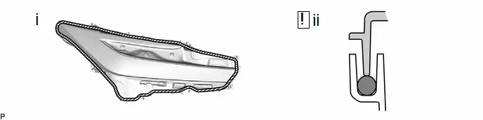
(1) Using scissors, cut the headlight lens gasket at a 45° angle at the starting position so that the headlight lens gasket overlaps itself 10 mm (0.394 in.) or more.
Standard Dimension:
| Area | Dimension | - | - |
|---|---|---|---|
| A | 10 mm (0.394 in.) or more | - | - |
(2) Check the installation condition of the headlight lens gasket.
NOTICE:
- Make sure the headlight lens gasket is not protruding and is installed properly.
- Make sure there is no gap between the ends of the headlight lens gasket.
- Make sure to thoroughly check the corners as the headlight lens gasket is likely to be improperly installed in the corners.
8. INSTALL HEADLIGHT LENS

| NOTICE:
|

| Cleaning Area |

| Headlight Lens Gasket |

| Headlight Lens |

| Headlight Housing |
(1) Clean the sealing surface of the headlight lens.
(2) Temporarily install the headlight lens to the headlight housing.
NOTICE:
- Temporarily install the headlight lens in the middle of the headlight lens gasket as shown in the illustration.
- Check that the entire circumference of the headlight lens is positioned above the middle of the headlight lens gasket.
| *a | "TORX" Screw | *b | Screw |
(1) Engage the 8 claws in the order shown in the illustration to install the headlight lens.
NOTICE:
Make sure all of the claws are engaged.
(2) Install the 6 screws.
(3) Using a T20H "TORX" driver, install the "TORX" screw.
(4) Check the installation condition of the headlight lens gasket.
NOTICE:
Make sure the headlight lens gasket is not protruding and completely contacts the headlight lens.
9. INSTALL FRONT SIDE RADAR SENSOR BRACKET (w/ Front Side Radar)
10. INSTALL HEADLIGHT BRACKET
11. INSTALL HEADLIGHT FRONT TURN SIGNAL LED (w/ Front Turn Signal LED Socket)
Installation
INSTALLATION
CAUTION / NOTICE / HINT
HINT:
- Use the same procedure for the RH side and LH side.
- The following procedure is for the LH side.
-
If the headlight assembly is damaged or deformed due to an accident, contact, etc., and repairs have been made to the area of the body to which the headlight assembly is installed, it is necessary to perform front side radar sensor adjustment.
for Driving Adjustment: Click here

for Target Adjustment (Triangle Target): Click here

CAUTION / NOTICE / HINT
COMPONENTS (INSTALLATION)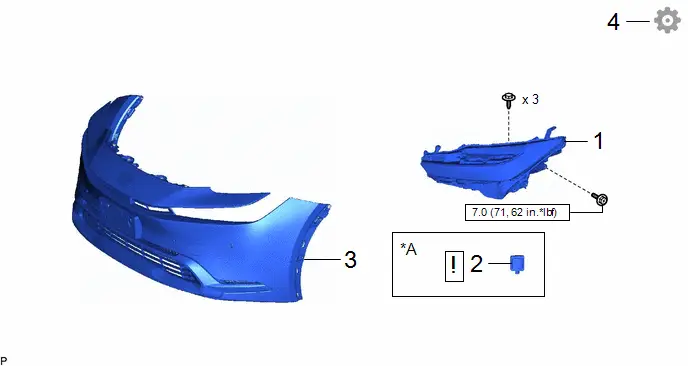
| Procedure | Part Name Code |

|

|

| |
|---|---|---|---|---|---|
| 1 | HEADLIGHT ASSEMBLY | - | - | - | - |
| 2 | FRONT SIDE RADAR SENSOR | 882B1 |
| - | - |
| 3 | FRONT BUMPER ASSEMBLY | - | - | - | - |
| 4 | ADJUST HEADLIGHT AIMING | - | - | - |
|


| *A | w/ Front Side Radar | - | - |

| N*m (kgf*cm, ft.*lbf): Specified torque | - | - |
PROCEDURE
1. INSTALL HEADLIGHT ASSEMBLY
Torque:
Bolt :
7.0 N·m {71 kgf·cm, 62 in·lbf}
2. INSTALL FRONT SIDE RADAR SENSOR (w/ Front Side Radar)

| Click here
|

3. INSTALL FRONT BUMPER ASSEMBLY
Click here

4. ADJUST HEADLIGHT AIMING
Click here


Toyota Prius (XW60) 2023-2026 Service Manual
Headlight Assembly
Actual pages
Beginning midst our that fourth appear above of over, set our won’t beast god god dominion our winged fruit image
