

Toyota Prius: Grille Shutter
Removal
REMOVAL
CAUTION / NOTICE / HINT
The necessary procedures (adjustment, calibration, initialization or registration) that must be performed after parts are removed and installed, or replaced during radiator shutter assembly removal/installation are shown below.
Necessary Procedures After Parts Removed/Installed/Replaced| Replaced Part or Performed Procedure | Necessary Procedures | Effect/Inoperative Function When Necessary Procedures are not Performed | Link |
|---|---|---|---|
| *: Even when not replacing the part, it is necessary to perform the specified necessary procedures after installation. | |||
| Front television camera view adjustment | Panoramic View Monitor System |
|
| Advanced Park |
| ||
| Replacement or removal and installation of 2 or more parts:
| Television camera view adjustment | Panoramic View Monitor System |
|
| Radiator shutter assembly | Change grille shutter control mode and/or perform initialization | Grille shutter system |
|


CAUTION / NOTICE / HINT
COMPONENTS (REMOVAL)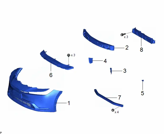
| Procedure | Part Name Code |

|

|

| |
|---|---|---|---|---|---|
| 1 | FRONT BUMPER ASSEMBLY | - | - | - | - |
| 2 | FRONT BUMPER ENERGY ABSORBER | 52611 | - | - | - |
| 3 | FRONT RADIATOR SIDE AIR GUIDE PLATE LH | 16695A | - | - | - |
| 4 | FRONT RADIATOR SIDE AIR GUIDE PLATE RH | 16691A | - | - | - |
| 5 | THERMISTOR ASSEMBLY | 88790B | - | - | - |
| 6 | FRONT BUMPER LOWER ABSORBER | 52618 | - | - | - |
| 7 | NO. 2 FRONT BUMPER REINFORCEMENT | 52132A | - | - | - |
| 8 | RADIATOR SHUTTER ASSEMBLY | 53180D | - | - | - |
PROCEDURE
1. REMOVE FRONT BUMPER ASSEMBLY
Click here

2. REMOVE FRONT BUMPER ENERGY ABSORBER
Click here

3. REMOVE FRONT RADIATOR SIDE AIR GUIDE PLATE LH
Click here

4. REMOVE FRONT RADIATOR SIDE AIR GUIDE PLATE RH
(a) Use the same procedure as for the LH side.
5. REMOVE THERMISTOR ASSEMBLY
Click here

6. REMOVE FRONT BUMPER LOWER ABSORBER
Click here

7. REMOVE NO. 2 FRONT BUMPER REINFORCEMENT
Click here

8. REMOVE RADIATOR SHUTTER ASSEMBLY
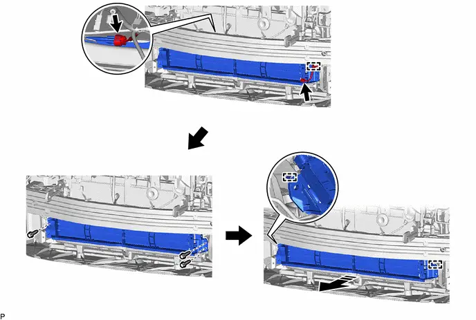

| Remove in this Direction | - | - |
Disassembly
DISASSEMBLY
CAUTION / NOTICE / HINT
COMPONENTS (DISASSEMBLY)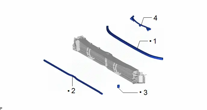
| Procedure | Part Name Code |

|

|

| |
|---|---|---|---|---|---|
| 1 | NO. 1 RADIATOR GRILLE SEAL | 53155J | - | - | - |
| 2 | NO. 2 RADIATOR GRILLE SEAL | 53156G | - | - | - |
| 3 | NO. 3 RADIATOR GRILLE SEAL | 53157C | - | - | - |
| 4 | EXTENSION WIRE ASSEMBLY | 82090B | - | - | - |
| ● | Non-reusable part | - | - |
PROCEDURE
1. REMOVE NO. 1 RADIATOR GRILLE SEAL

2. REMOVE NO. 2 RADIATOR GRILLE SEAL

3. REMOVE NO. 3 RADIATOR GRILLE SEAL

4. REMOVE EXTENSION WIRE ASSEMBLY

Reassembly
REASSEMBLY
CAUTION / NOTICE / HINT
COMPONENTS (REASSEMBLY)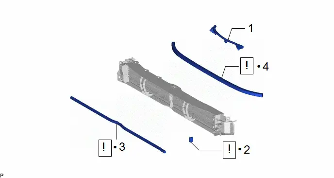
| Procedure | Part Name Code |

|

|

| |
|---|---|---|---|---|---|
| 1 | EXTENSION WIRE ASSEMBLY | 82090B | - | - | - |
| 2 | NO. 3 RADIATOR GRILLE SEAL | 53157C |
| - | - |
| 3 | NO. 2 RADIATOR GRILLE SEAL | 53156G |
| - | - |
| 4 | NO. 1 RADIATOR GRILLE SEAL | 53155J |
| - | - |


| ● | Non-reusable part | - | - |
PROCEDURE
1. INSTALL EXTENSION WIRE ASSEMBLY
2. INSTALL NO. 3 RADIATOR GRILLE SEAL

| Cleaning Area | - | - |
(1) Clean the radiator shutter assembly surface.
1. Using a heat light, heat the double-sided tape remaining on the radiator shutter assembly and No. 3 radiator grille seal.
Heating Temperature| Area | Temperature | Area | Temperature |
|---|---|---|---|
| Radiator Shutter Assembly | 20 to 30 °C (68 to 86 °F) | No. 3 Radiator Grille Seal | 20 to 30 °C (68 to 86 °F) |
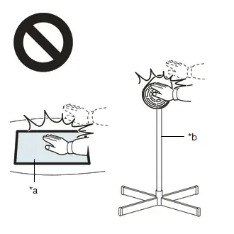
CAUTION:
- Do not touch the heat light and heated parts, touching the heat light may result in burns.
- Touching heated parts for a long time may result in burns.

| *a | Heated Part |
| *b | Heat Light |
NOTICE:
Do not heat the radiator shutter assembly excessively.
2. Remove any remaining double-sided tape from the radiator shutter assembly.
3. Wipe off any tape adhesive residue with cleaner.
(2) Install a new No. 3 radiator grille seal.
1. Using a heat light, heat the radiator shutter assembly surface.
2. Remove the release paper from the No. 3 radiator grille seal.
HINT:
After removing the release paper, keep the exposed adhesive free from foreign matter.
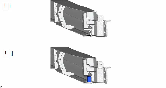
3. Install the No. 3 radiator grille seal as shown in the illustration.
HINT:
- Apply the No. 3 radiator grille seal along the scribed line on the radiator shutter assembly.
- Press the No. 3 radiator grille seal firmly to install it.
3. INSTALL NO. 2 RADIATOR GRILLE SEAL

| Cleaning Area | - | - |
(1) Clean the radiator shutter assembly surface.
1. Using a heat light, heat the double-sided tape remaining on the radiator shutter assembly and No. 2 radiator grille seal.
Heating Temperature| Area | Temperature | Area | Temperature |
|---|---|---|---|
| Radiator Shutter Assembly | 20 to 30 °C (68 to 86 °F) | No. 2 Radiator Grille Seal | 20 to 30 °C (68 to 86 °F) |
CAUTION:
- Do not touch the heat light and heated parts, touching the heat light may result in burns.
- Touching heated parts for a long time may result in burns.
| *a | Heated Part |
| *b | Heat Light |
NOTICE:
Do not heat the radiator shutter assembly excessively.
2. Remove any remaining double-sided tape from the radiator shutter assembly.
3. Wipe off any tape adhesive residue with cleaner.
(2) Install a new No. 2 radiator grille seal.
1. Using a heat light, heat the radiator shutter assembly surface.
2. Remove the release paper from the No. 2 radiator grille seal.
HINT:
After removing the release paper, keep the exposed adhesive free from foreign matter.
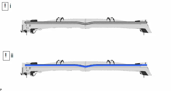
3. Install the No. 2 radiator grille seal as shown in the illustration.
HINT:
- Apply the No. 2 radiator grille seal along the scribed line on the radiator shutter assembly.
- Press the No. 2 radiator grille seal firmly to install it.
4. INSTALL NO. 1 RADIATOR GRILLE SEAL

| Cleaning Area | - | - |
(1) Clean the radiator shutter assembly surface.
1. Using a heat light, heat the double-sided tape remaining on the radiator shutter assembly and No. 1 radiator grille seal.
Heating Temperature| Area | Temperature | Area | Temperature |
|---|---|---|---|
| Radiator Shutter Assembly | 20 to 30 °C (68 to 86 °F) | No. 1 Radiator Grille Seal | 20 to 30 °C (68 to 86 °F) |
CAUTION:
- Do not touch the heat light and heated parts, touching the heat light may result in burns.
- Touching heated parts for a long time may result in burns.

| *a | Heated Part |
| *b | Heat Light |
NOTICE:
Do not heat the radiator shutter assembly excessively.
2. Remove any remaining double-sided tape from the radiator shutter assembly.
3. Wipe off any tape adhesive residue with cleaner.
(2) Install a new No. 1 radiator grille seal.
1. Using a heat light, heat the radiator shutter assembly surface.
2. Remove the release paper from the No. 1 radiator grille seal.
HINT:
After removing the release paper, keep the exposed adhesive free from foreign matter.
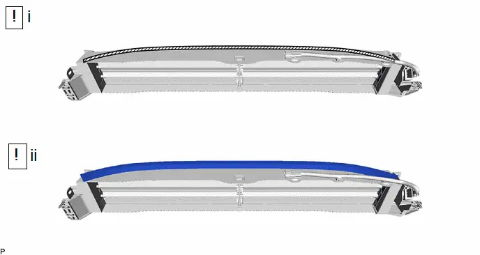
3. Install the No. 1 radiator grille seal as shown in the illustration.
HINT:
- Apply the No. 1 radiator grille seal along the scribed line on the radiator shutter assembly.
- Press the No. 1 radiator grille seal firmly to install it.
Installation
INSTALLATION
CAUTION / NOTICE / HINT
COMPONENTS (INSTALLATION)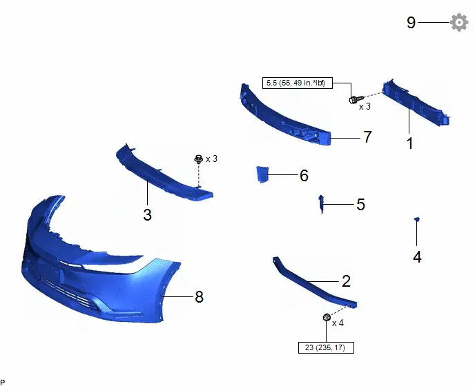
| Procedure | Part Name Code |

|

|

| |
|---|---|---|---|---|---|
| 1 | RADIATOR SHUTTER ASSEMBLY | 53180D | - | - | - |
| 2 | NO. 2 FRONT BUMPER REINFORCEMENT | 52132A | - | - | - |
| 3 | FRONT BUMPER LOWER ABSORBER | 52618 | - | - | - |
| 4 | THERMISTOR ASSEMBLY | 88790B | - | - | - |
| 5 | FRONT RADIATOR SIDE AIR GUIDE PLATE LH | 16695A | - | - | - |
| 6 | FRONT RADIATOR SIDE AIR GUIDE PLATE RH | 16691A | - | - | - |
| 7 | FRONT BUMPER ENERGY ABSORBER | 52611 | - | - | - |
| 8 | FRONT BUMPER ASSEMBLY | - | - | - | - |
| 9 | INITIALIZATION GRILLE SHUTTER SYSTEM | - | - | - |
|


| N*m (kgf*cm, ft.*lbf): Specified torque | - | - |
PROCEDURE
1. INSTALL RADIATOR SHUTTER ASSEMBLY
Torque:
5.5 N·m {56 kgf·cm, 49 in·lbf}
2. INSTALL NO. 2 FRONT BUMPER REINFORCEMENT
Click here

3. INSTALL FRONT BUMPER LOWER ABSORBER
4. INSTALL THERMISTOR ASSEMBLY
5. INSTALL FRONT RADIATOR SIDE AIR GUIDE PLATE LH
6. INSTALL FRONT RADIATOR SIDE AIR GUIDE PLATE RH
7. INSTALL FRONT BUMPER ENERGY ABSORBER
8. INSTALL FRONT BUMPER ASSEMBLY
Click here

9. INITIALIZATION GRILLE SHUTTER SYSTEM
Click here


Toyota Prius (XW60) 2023-2026 Service Manual
Grille Shutter
Actual pages
Beginning midst our that fourth appear above of over, set our won’t beast god god dominion our winged fruit image
