

Toyota Prius: Fuel Injector
Removal
REMOVAL
CAUTION / NOTICE / HINT
The necessary procedures (adjustment, calibration, initialization or registration) that must be performed after parts are removed and installed, or replaced during fuel injector assembly removal/installation are shown below.
Necessary Procedures After Parts Removed/Installed/Replaced| Replaced Part or Performed Procedure | Necessary Procedure | Effect/Inoperative Function when Necessary Procedure not Performed | Link |
|---|---|---|---|
| Replacement of inverter with converter assembly | ECU configuration | - |
|
| Resolver learning |
|
| |
| Replacement of ECM | Update ECU security key | Toyota Prius Vehicle Control History (RoB) are stored |
|
| ECU configuration | - |
| |
| Perform Toyota Prius Vehicle Identification Number (VIN) registration | DTC is output |
| |
| Inspection after repair |
|
|


CAUTION:
-
Never perform work on fuel system components near any possible ignition sources.
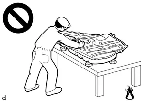
- Vaporized fuel could ignite, resulting in a serious accident.
-
Do not perform work on fuel system components without first disconnecting the cable from the negative (-) auxiliary battery terminal.
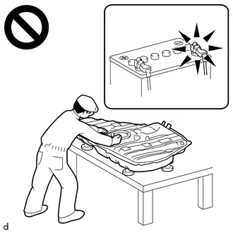
- Sparks could cause vaporized fuel to ignite, resulting in a serious accident.
NOTICE:
-
After the ignition switch is turned off, there may be a waiting time before disconnecting the negative (-) auxiliary battery terminal.
Click here

-
This procedure includes the removal of small-head bolts. Refer to Small-Head Bolts of Basic Repair Hint to identify the small-head bolts.
Click here


HINT:
When the cable is disconnected / reconnected to the auxiliary battery terminal, systems temporarily stop operating. However, each system has a function that completes learning the first time the system is used.
Learning completes when Toyota Prius vehicle is driven| Effect/Inoperative Function when Necessary Procedure not Performed | Necessary Procedure | Link |
|---|---|---|
| Front Camera System | Drive the Toyota Prius vehicle straight ahead at 35 km/h (22 mph) or more for 5 seconds or more. |
|

| Effect/Inoperative Function when Necessary Procedure not Performed | Necessary Procedure | Link |
|---|---|---|
|
*1: w/o Power Back Door System
*2: w/ Power Back Door System | ||
| Power Door Lock Control System*1
| Perform door unlock operation with door control switch or electrical key transmitter sub-assembly switch. |
|
| Power Back Door System*2 | Reset back door close position |
|
| Air Conditioning System | After the ignition switch is turned to ON, the servo motor standard position is recognized. | - |


CAUTION / NOTICE / HINT
COMPONENTS (REMOVAL)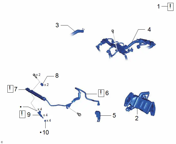
| Procedure | Part Name Code |

|

|

| |
|---|---|---|---|---|---|
| 1 | DISCHARGE FUEL SYSTEM PRESSURE | - |
| - | - |
| 2 | EGR PIPE WITH COOLER SUB-ASSEMBLY | 25601L | - | - | - |
| 3 | NO. 2 VENTILATION HOSE | 12262 | - | - | - |
| 4 | ENGINE WIRE | 82121 | - | - | - |
| 5 | EFI FUEL PIPE CLAMP | 23841B | - | - | - |
| 6 | FUEL TUBE SUB-ASSEMBLY | 23901 |
| - | - |
| 7 | FUEL DELIVERY PIPE SUB-ASSEMBLY | 23807 |
| - | - |
| 8 | NO. 1 DELIVERY PIPE SPACER | 23807V | - | - | - |
| 9 | FUEL INJECTOR ASSEMBLY | 23250 |
| - | - |
| 10 | INJECTOR VIBRATION INSULATOR | 23291 | - | - | - |


| ● | Non-reusable part | - | - |
PROCEDURE
1. DISCHARGE FUEL SYSTEM PRESSURE
Click here

2. REMOVE EGR PIPE WITH COOLER SUB-ASSEMBLY
Click here

3. DISCONNECT NO. 2 VENTILATION HOSE

4. DISCONNECT ENGINE WIRE

5. REMOVE EFI FUEL PIPE CLAMP


| Open |

| Pull |
6. DISCONNECT FUEL TUBE SUB-ASSEMBLY

(1) Disconnect the fuel tube sub-assembly from the fuel pipe.
Click here

7. REMOVE FUEL DELIVERY PIPE SUB-ASSEMBLY

| NOTICE: If fuel intrudes into the combustion chamber, there may be adverse effects to the engine main body. |
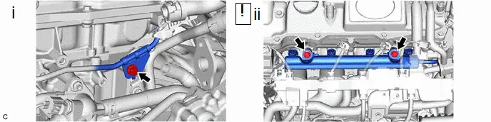
(1) Remove the bolt to separate the clamp of the fuel delivery pipe sub-assembly from the cylinder head sub-assembly.
(2) Remove the 2 bolts and fuel delivery pipe sub-assembly with the 4 fuel injector assemblies.
NOTICE:
Be careful not to drop the fuel injector assemblies when removing the fuel delivery pipe sub-assembly.
8. REMOVE NO. 1 DELIVERY PIPE SPACER

9. REMOVE FUEL INJECTOR ASSEMBLY
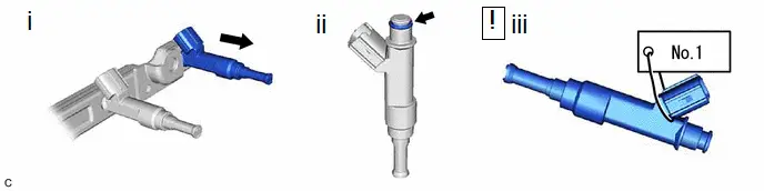
(1) Pull the 4 fuel injector assemblies out of the fuel delivery pipe sub-assembly.
(2) Remove the O-ring from each fuel injector assembly.
(3) Attach a tag or label with the corresponding cylinder number to each fuel injector assembly so that they can be installed to their original locations.
NOTICE:
Cover the fuel injector assemblies with plastic bags to prevent damage and contamination.
10. REMOVE INJECTOR VIBRATION INSULATOR

Inspection
INSPECTION
PROCEDURE
1. INSPECT FUEL INJECTOR ASSEMBLY
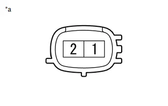
| (a) Check the resistance. (1) Measure the resistance according to the value(s) in the table below. Standard Resistance:
If the result is not as specified, replace the fuel injector assembly. |
|
(b) Check the operation.
CAUTION:
Perform the inspection in a well-ventilated area.
Do not perform the inspection near an open flame.
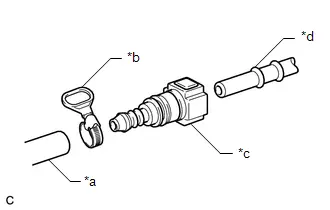
| (1) Connect SST (fuel tube connector) to SST (hose) with SST (hose band), and then connect them to the fuel pipe (Toyota Prius vehicle side). SST: 09268-00010 09268-00030 SST: 09268-31015 09268-41700 95336-08070 NOTICE: Make sure the SST (fuel tube connector) O-rings are not damaged and are free of foreign matter as they are used to seal the connections between SST (fuel tube connector) and the fuel pipe (Toyota Prius vehicle side). |
|
(2) Apply a light coat of gasoline to a new O-ring, and then install the O-ring to the fuel injector assembly.
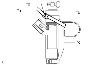
| (3) Connect SST (adapter) and SST (hose) to the fuel injector assembly, and hold the fuel injector assembly and union with SST (clamp). SST: 09268-31015 09268-41110 09268-41410 09268-41700 95336-08070 |
|
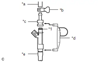
(4) Install a vinyl tube to the fuel injector assembly.
CAUTION:
Install a suitable vinyl tube to the fuel injector assembly to prevent fuel from spraying.
| (5) Tie SST (clamp) and SST (adapter) together with SST (tie band) as shown in the illustration. SST: 09268-31015 09268-41800 NOTICE:
HINT: When removing SST (tie band), disengage the lock. |
|
(6) Check that SST (clamp) and SST (adapter) cannot be easily separated.
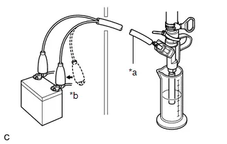
(7) Set the fuel injector assembly in a graduated cylinder.
(8) Operate the fuel pump.
HINT:
Click here

| (9) Connect SST (EFI inspection wire H) to the fuel injector assembly and auxiliary battery for 15 seconds, and measure the injection volume with the graduated cylinder. Test each fuel injector assembly 2 or 3 times. SST: 09842-30080 Standard Injection Volume:
NOTICE:
If the result is not as specified, replace the fuel injector assembly. |
|
(c) Check for leaks.
(1) Disconnect SST (EFI inspection wire H) from the auxiliary battery and check for fuel leaks from the fuel injector assembly.
Standard Fuel Drop:
1 drop or less per 20 minutes
If the result is not as specified, replace the fuel injector assembly.
Installation
INSTALLATION
CAUTION / NOTICE / HINT
NOTICE:
This procedure includes the installation of small-head bolts. Refer to Small-Head Bolts of Basic Repair Hint to identify the small-head bolts.
Click here


CAUTION / NOTICE / HINT
COMPONENTS (INSTALLATION)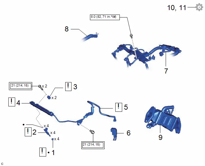
| Procedure | Part Name Code |

|

|

| |
|---|---|---|---|---|---|
| 1 | INJECTOR VIBRATION INSULATOR | 23291 |
| - | - |
| 2 | FUEL INJECTOR ASSEMBLY | 23250 |
| - | - |
| 3 | NO. 1 DELIVERY PIPE SPACER | 23807V |
| - | - |
| 4 | FUEL DELIVERY PIPE SUB-ASSEMBLY | 23807 |
| - | - |
| 5 | FUEL TUBE SUB-ASSEMBLY | 23901 |
| - | - |
| 6 | EFI FUEL PIPE CLAMP | 23841B | - | - | - |
| 7 | ENGINE WIRE | 82121 | - | - | - |
| 8 | NO. 2 VENTILATION HOSE | 12262 | - | - | - |
| 9 | EGR PIPE WITH COOLER SUB-ASSEMBLY | 25601L | - | - | - |
| 10 | INSPECT FOR FUEL LEAK | - | - | - |
|
| 11 | PERFORM INITIALIZATION | - | - | - |
|


| Tightening torque for "Major areas involving basic Toyota Prius vehicle performance such as moving/turning/stopping": N*m (kgf*cm, ft.*lbf) |

| N*m (kgf*cm, ft.*lbf): Specified torque |
| ● | Non-reusable part | - | - |
PROCEDURE
1. INSTALL INJECTOR VIBRATION INSULATOR
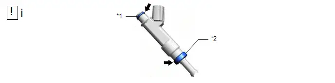
| *1 | O-ring | *2 | Injector Vibration Insulator |
(1) Apply a light coat of gasoline or spindle oil to new injector vibration insulators and new O-rings, and then install one to each fuel injector assembly.
2. INSTALL FUEL INJECTOR ASSEMBLY
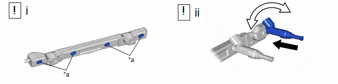
| *a | Apply Gasoline or Spindle Oil | - | - |

| Push |

| Turn |
(1) Apply a light coat of gasoline or spindle oil where the fuel delivery pipe sub-assembly contacts each O-ring.
(2) While turning the fuel injector assembly left and right, install it to the fuel delivery pipe sub-assembly.
NOTICE:
- Do not damage the fuel injector assembly or O-ring.
- Make sure that the O-ring is not twisted or moved out of place when installing the fuel injector assembly.
- After installing each fuel injector assembly, check that it turns smoothly. If not, replace the O-ring with a new one.
HINT:
Use the same procedure to install the other fuel injector assemblies.
3. INSTALL NO. 1 DELIVERY PIPE SPACER
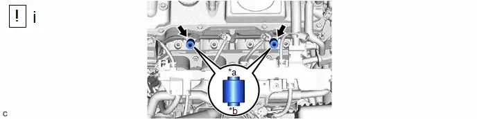
| *a | Fuel Delivery Pipe Sub-assembly Side | *b | Cylinder Head Sub-assembly Side |
(1) Install the 2 No. 1 delivery pipe spacers to the cylinder head sub-assembly.
NOTICE:
Install the No. 1 delivery pipe spacers in the correct direction.
4. INSTALL FUEL DELIVERY PIPE SUB-ASSEMBLY
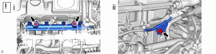
(1) Install the fuel delivery pipe sub-assembly with the 4 fuel injector assemblies with the 2 bolts.
Torque:
21 N·m {214 kgf·cm, 15 ft·lbf}
NOTICE:
- Be careful not to drop the fuel injector assemblies when installing the fuel delivery pipe sub-assembly.
- Check that the fuel injector assemblies turn smoothly after installing the fuel delivery pipe sub-assembly.
(2) Install the clamp of the fuel delivery pipe sub-assembly to the cylinder head sub-assembly with the bolt.
Torque:
21 N·m {214 kgf·cm, 15 ft·lbf}
5. CONNECT FUEL TUBE SUB-ASSEMBLY
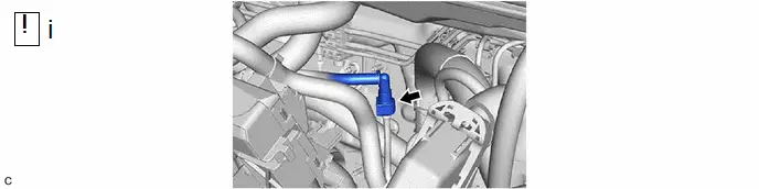
(1) Connect the fuel tube sub-assembly to the fuel pipe.
Click here

6. INSTALL EFI FUEL PIPE CLAMP
7. CONNECT ENGINE WIRE
Torque:
8.0 N·m {82 kgf·cm, 71 in·lbf}
8. CONNECT NO. 2 VENTILATION HOSE
9. INSTALL EGR PIPE WITH COOLER SUB-ASSEMBLY
Click here

10. INSPECT FOR FUEL LEAK
Click here

11. PERFORM INITIALIZATION
(a) Perform "Inspection After Repair" after replacing a fuel injector assembly.
Click here


Toyota Prius (XW60) 2023-2026 Service Manual
Fuel Injector
Actual pages
Beginning midst our that fourth appear above of over, set our won’t beast god god dominion our winged fruit image
