

Toyota Prius: Fuel Filter
Components
COMPONENTS
ILLUSTRATION
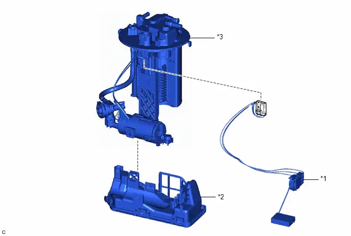
| *1 | FUEL SENDER GAUGE ASSEMBLY | *2 | FUEL FILTER (FUEL SUB-TANK SUB-ASSEMBLY) |
| *3 | FUEL SUCTION PLATE SUB-ASSEMBLY | - | - |
Replacement
REPLACEMENT
CAUTION / NOTICE / HINT
The necessary procedures (adjustment, calibration, initialization or registration) that must be performed after parts are removed and installed, or replaced during fuel filter (fuel sub-tank sub-assembly) removal/installation are shown below.
CAUTION:
-
Never perform work on fuel system components near any possible ignition sources.
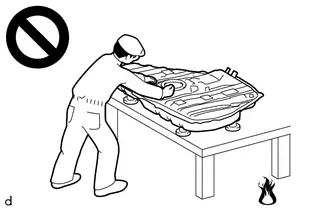
- Vaporized fuel could ignite, resulting in a serious accident.
-
Do not perform work on fuel system components without first disconnecting the cable from the negative (-) auxiliary battery terminal.
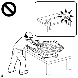
- Sparks could cause vaporized fuel to ignite, resulting in a serious accident.
NOTICE:
-
After the ignition switch is turned off, there may be a waiting time before disconnecting the negative (-) auxiliary battery terminal.
Click here

-
Do not disconnect the tube shown in the illustration when disassembling the fuel suction tube with pump and gauge assembly. Doing so will cause reassembly of the fuel suction tube with pump and gauge assembly to be impossible as the tube is pressed into the fuel suction plate sub-assembly.
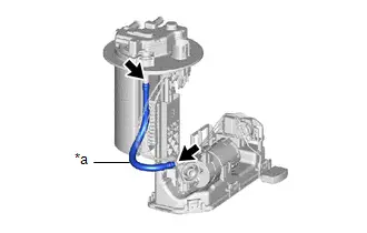
*a
Tube
HINT:
When the cable is disconnected / reconnected to the auxiliary battery terminal, systems temporarily stop operating. However, each system has a function that completes learning the first time the system is used.
Learning completes when Toyota Prius vehicle is driven| Effect/Inoperative Function when Necessary Procedure not Performed | Necessary Procedure | Link |
|---|---|---|
| Front Camera System | Drive the Toyota Prius vehicle straight ahead at 35 km/h (22 mph) or more for 5 seconds or more. |
|

| Effect/Inoperative Function when Necessary Procedure not Performed | Necessary Procedure | Link |
|---|---|---|
|
*1: w/o Power Back Door System
*2: w/ Power Back Door System | ||
| Power Door Lock Control System*1
| Perform door unlock operation with door control switch or electrical key transmitter sub-assembly switch. |
|
| Power Back Door System*2 | Reset back door close position |
|
| Air Conditioning System | After the ignition switch is turned to ON, the servo motor standard position is recognized. | - |


PROCEDURE
1. REMOVE FUEL SUCTION TUBE WITH PUMP AND GAUGE ASSEMBLY
Click here

2. REMOVE FUEL SENDER GAUGE ASSEMBLY
Click here

3. REMOVE FUEL FILTER (FUEL SUB-TANK SUB-ASSEMBLY)
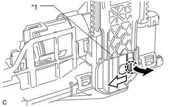
| *1 | Fuel Suction Plate Sub-assembly |

| Pull |

| Slide |
(a) Disengage the claw and slide the fuel filter (fuel sub-tank sub-assembly) and then separate it from the fuel suction plate sub-assembly.
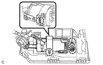
| (b) Disengage the 4 claws and remove the fuel suction plate sub-assembly from the fuel filter (fuel sub-tank sub-assembly). |
|
4. INSTALL FUEL FILTER (FUEL SUB-TANK SUB-ASSEMBLY)
(a) Engage the 4 claws to install the fuel suction plate sub-assembly to the fuel filter (fuel sub-tank sub-assembly).
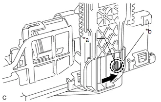
| *a | Protrusion |
| *b | Installation Hole |

| Slide |
(b) Align the protrusion of the fuel filter (fuel sub-tank sub-assembly) with the installation hole of the fuel suction plate sub-assembly and then slide the fuel fuel filter (fuel sub-tank sub-assembly) to install it to the fuel suction plate sub-assembly.
5. INSTALL FUEL SENDER GAUGE ASSEMBLY
Click here

6. INSTALL FUEL SUCTION TUBE WITH PUMP AND GAUGE ASSEMBLY
Click here


Toyota Prius (XW60) 2023-2026 Service Manual
Actual pages
Beginning midst our that fourth appear above of over, set our won’t beast god god dominion our winged fruit image
