

Toyota Prius: Fuel Pressure Regulator
Removal
REMOVAL
CAUTION / NOTICE / HINT
The necessary procedures (adjustment, calibration, initialization or registration) that must be performed after parts are removed and installed, or replaced during fuel pressure regulator assembly removal/installation are shown below.
CAUTION:
-
Never perform work on fuel system components near any possible ignition sources.
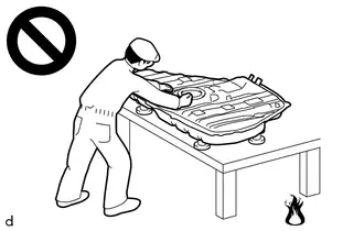
- Vaporized fuel could ignite, resulting in a serious accident.
-
Do not perform work on fuel system components without first disconnecting the cable from the negative (-) auxiliary battery terminal.
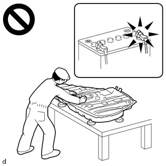
- Sparks could cause vaporized fuel to ignite, resulting in a serious accident.
NOTICE:
After the ignition switch is turned off, there may be a waiting time before disconnecting the negative (-) auxiliary battery terminal.
Click here

HINT:
When the cable is disconnected / reconnected to the auxiliary battery terminal, systems temporarily stop operating. However, each system has a function that completes learning the first time the system is used.
Learning completes when Toyota Prius vehicle is driven| Effect/Inoperative Function when Necessary Procedure not Performed | Necessary Procedure | Link |
|---|---|---|
| Front Camera System | Drive the Toyota Prius vehicle straight ahead at 35 km/h (22 mph) or more for 5 seconds or more. |
|

| Effect/Inoperative Function when Necessary Procedure not Performed | Necessary Procedure | Link |
|---|---|---|
|
*1: w/o Power Back Door System
*2: w/ Power Back Door System | ||
| Power Door Lock Control System*1
| Perform door unlock operation with door control switch or electrical key transmitter sub-assembly switch. |
|
| Power Back Door System*2 | Reset back door close position |
|
| Air Conditioning System | After the ignition switch is turned to ON, the servo motor standard position is recognized. | - |


CAUTION / NOTICE / HINT
COMPONENTS (REMOVAL)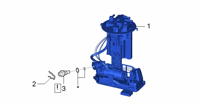
| Procedure | Part Name Code |

|

|

| |
|---|---|---|---|---|---|
| 1 | FUEL SUCTION TUBE WITH PUMP AND GAUGE ASSEMBLY | 77020A | - | - | - |
| 2 | NO. 2 FUEL SUCTION SUPPORT | 77175 | - | - | - |
| 3 | FUEL PRESSURE REGULATOR ASSEMBLY | 23280J |
| - | - |

| ● | Non-reusable part | - | - |
PROCEDURE
1. REMOVE FUEL SUCTION TUBE WITH PUMP AND GAUGE ASSEMBLY
Click here

2. REMOVE NO. 2 FUEL SUCTION SUPPORT

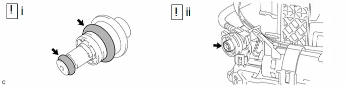
3. REMOVE FUEL PRESSURE REGULATOR ASSEMBLY
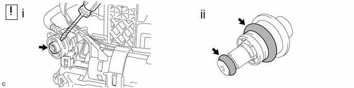
(1) Using a screwdriver with its tip wrapped with protective tape, remove the fuel pressure regulator assembly from the fuel suction tube with pump and gauge assembly.
NOTICE:
- Pull out the fuel pressure regulator assembly carefully because the O-rings are firmly installed between the fuel pressure regulator assembly and the fuel suction tube with pump and gauge assembly.
- Do not damage the fuel suction tube with pump and gauge assembly.
(2) Remove the 2 O-rings from the fuel pressure regulator assembly.
Installation
INSTALLATION
CAUTION / NOTICE / HINT
COMPONENTS (INSTALLATION)
| Procedure | Part Name Code |

|

|

| |
|---|---|---|---|---|---|
| 1 | FUEL PRESSURE REGULATOR ASSEMBLY | 23280J |
| - | - |
| 2 | NO. 2 FUEL SUCTION SUPPORT | 77175 | - | - | - |
| 3 | FUEL SUCTION TUBE WITH PUMP AND GAUGE ASSEMBLY | 77020A | - | - | - |

| ● | Non-reusable part | - | - |
PROCEDURE
1. INSTALL FUEL PRESSURE REGULATOR ASSEMBLY
(1) Apply gasoline to 2 new O-rings. Then install the O-rings to the fuel pressure regulator assembly.
(2) Install the fuel pressure regulator assembly to the fuel suction tube with pump and gauge assembly.
NOTICE:
Make sure that the O-rings are not cut or pinched during installation.
2. INSTALL NO. 2 FUEL SUCTION SUPPORT
3. INSTALL FUEL SUCTION TUBE WITH PUMP AND GAUGE ASSEMBLY
Click here


Toyota Prius (XW60) 2023-2026 Service Manual
Actual pages
Beginning midst our that fourth appear above of over, set our won’t beast god god dominion our winged fruit image
