

Toyota Prius: Front Stabilizer Bar
Removal
REMOVAL
CAUTION / NOTICE / HINT
The necessary procedures (adjustment, calibration, initialization, or registration) that must be performed after parts are removed and installed, or replaced during the front stabilizer bar removal/installation are shown below.
Necessary Procedures After Parts Removed/Installed/Replaced| Replaced Part or Performed Procedure | Necessary Procedure | Effect/Inoperative Function when Necessary Procedure not Performed | Link |
|---|---|---|---|
|
*: Even when not replacing the part, it is necessary to perform the specified necessary procedures after installation.
*1: Also necessary after performing a tire rotation. *2: It is not necessary to perform this procedure if the tire pressure warning valve and transmitters are installed to the same location. *3: The Toyota Prius vehicle height changes because of tire replacement. *4: If matchmarks were not placed when removing parts related to steering operation, perform end position initial setting. | |||
| Front wheel alignment adjustment | Perform "Calibration" |
|
|
| Suspension parts | Rear television camera assembly optical axis (Back camera position setting) | Parking Assist Monitor System |
|
| Parking assist ECU initialization | Panoramic View Monitor System |
| |
| Advanced Park |
| ||
| Tires |
| Tire Pressure Warning System | Refer to Procedures Necessary When Replacing Parts (for Tire Pressure Warning System)
|
| Rear television camera assembly optical axis (Back camera position setting) | Parking Assist Monitor System |
| |
| Parking assist ECU initialization*3 | Panoramic View Monitor System |
| |
| Advanced Park |
| ||
| End position initial setting | - |
|
| Front bumper assembly* | Front television camera view adjustment | Panoramic View Monitor System |
|
| Advanced Park |
| ||


CAUTION / NOTICE / HINT
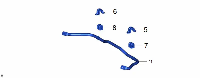
COMPONENTS (REMOVAL)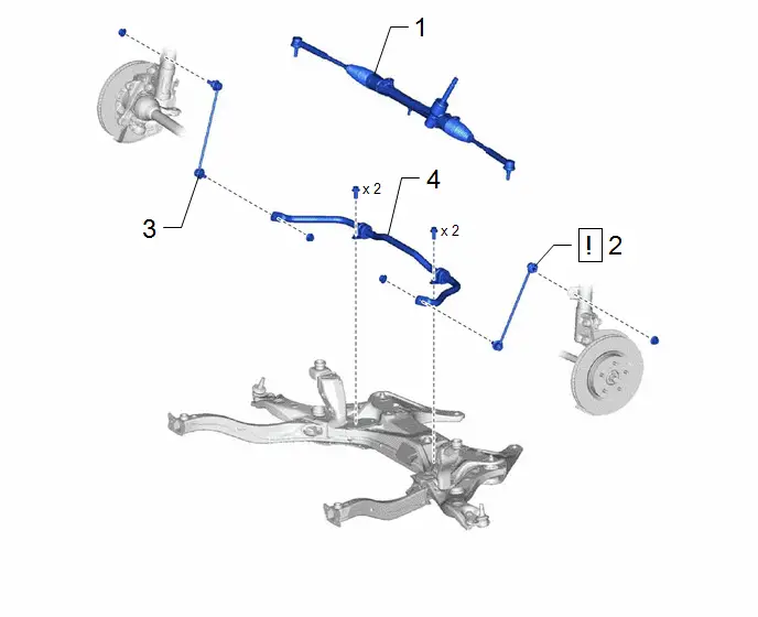
| Procedure | Part Name Code |

|

|

| |
|---|---|---|---|---|---|
| 1 | STEERING LINK ASSEMBLY | - | - | - | - |
| 2 | FRONT STABILIZER LINK ASSEMBLY LH | 48810 |
| - | - |
| 3 | FRONT STABILIZER LINK ASSEMBLY RH | 48820B | - | - | - |
| 4 | FRONT STABILIZER BAR | 48811 | - | - | - |

| Procedure | Part Name Code |

|

|

| |
|---|---|---|---|---|---|
| 5 | FRONT NO. 1 STABILIZER BRACKET LH | 48829A | - | - | - |
| 6 | FRONT NO. 1 STABILIZER BRACKET RH | 48824A | - | - | - |
| 7 | FRONT STABILIZER BAR BUSHING LH | 48815E | - | - | - |
| 8 | FRONT STABILIZER BAR BUSHING RH | 48815D | - | - | - |
| *1 | FRONT STABILIZER BAR | - | - |
PROCEDURE
1. REMOVE STEERING LINK ASSEMBLY
Click here


2. REMOVE FRONT STABILIZER LINK ASSEMBLY LH
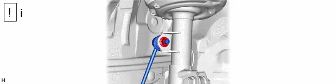
(1) Remove the nut and front stabilizer link assembly from the front shock absorber assembly.
NOTICE:
Do not damage the boot of the ball joint.
HINT:
If the ball joint turns together with the nut, use a 6 mm hexagon socket wrench to hold the stud bolt.
3. REMOVE FRONT STABILIZER LINK ASSEMBLY RH
(a) Perform the same procedure as for the LH side.
4. REMOVE FRONT STABILIZER BAR


| Front of the Toyota Prius Vehicle | - | - |
5. REMOVE FRONT NO. 1 STABILIZER BRACKET LH

6. REMOVE FRONT NO. 1 STABILIZER BRACKET RH
(a) Perform the same procedure as for the LH side.
7. REMOVE FRONT STABILIZER BAR BUSHING LH

8. REMOVE FRONT STABILIZER BAR BUSHING RH
(a) Perform the same procedure as for the LH side.
Inspection
INSPECTION
PROCEDURE
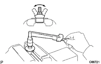
1. INSPECT FRONT STABILIZER LINK ASSEMBLY
| (a) Inspect the turning torque of the ball joint. (1) Secure the front stabilizer link assembly in a vise using aluminum plates. NOTICE: Do not overtighten the vise. (2) Install the nut to the front stabilizer link assembly stud. (3) Using a torque wrench, turn the stud continuously at a rate of 3 to 5 seconds per turn and take the torque reading on the 5th turn. Standard Turning Torque
(4) If the turning torque is not within the specified range, replace the front stabilizer link assembly with a new one. (5) Turn the stud to check that the stud does not catch and there is no play (6) If the stud catches or there is play while turning, replace the front stabilizer link assembly with a new one. |
|
(b) Inspect the dust cover.
(1) Check that the dust cover is not cracked and that there is no grease on it.
(2) If the dust cover is cracked or there is grease on it, replace the front stabilizer link assembly with a new one.
Installation
INSTALLATION
CAUTION / NOTICE / HINT
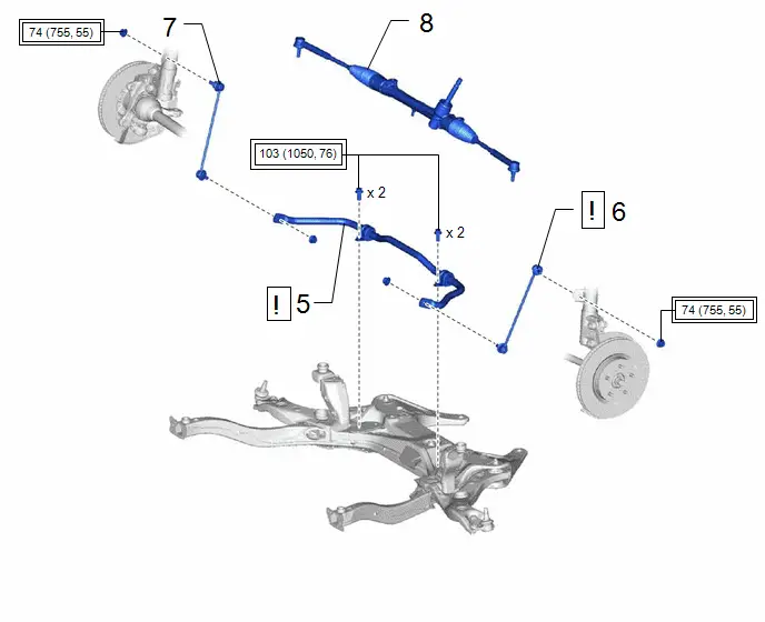
COMPONENTS (INSTALLATION)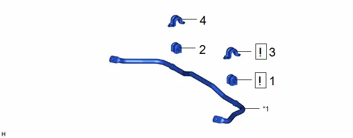
| Procedure | Part Name Code |

|

|

| |
|---|---|---|---|---|---|
| 1 | FRONT STABILIZER BAR BUSHING LH | 48815E |
| - | - |
| 2 | FRONT STABILIZER BAR BUSHING RH | 48815D | - | - | - |
| 3 | FRONT NO. 1 STABILIZER BRACKET LH | 48829A |
| - | - |
| 4 | FRONT NO. 1 STABILIZER BRACKET RH | 48824A | - | - | - |


| *1 | FRONT STABILIZER BAR | - | - |
| Procedure | Part Name Code |

|

|

| |
|---|---|---|---|---|---|
| 5 | FRONT STABILIZER BAR | 48811 |
| - | - |
| 6 | FRONT STABILIZER LINK ASSEMBLY LH | 48810 |
| - | - |
| 7 | FRONT STABILIZER LINK ASSEMBLY RH | 48820B | - | - | - |
| 8 | STEERING LINK ASSEMBLY | - | - | - | - |


| Tightening torque for "Major areas involving basic Toyota Prius vehicle performance such as moving/turning/stopping" : N*m (kgf*cm, ft.*lbf) | - | - |
PROCEDURE
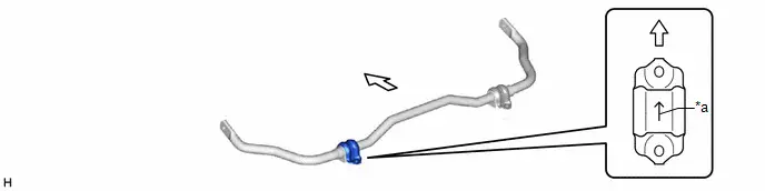
1. INSTALL FRONT STABILIZER BAR BUSHING LH

| NOTICE:
|

| *a | Stopper Ring | *b | Cutout |

| Front of the Toyota Prius Vehicle |

| Outside of the Vehicle |
2. INSTALL FRONT STABILIZER BAR BUSHING RH
3. INSTALL FRONT NO. 1 STABILIZER BRACKET LH

| NOTICE: Make sure to install the front No. 1 stabilizer bracket LH with its arrow facing the front of the Toyota Prius vehicle. |
| *a | Arrow | - | - |

| Front of the Toyota Prius Vehicle | - | - |
4. INSTALL FRONT NO. 1 STABILIZER BRACKET RH
5. INSTALL FRONT STABILIZER BAR
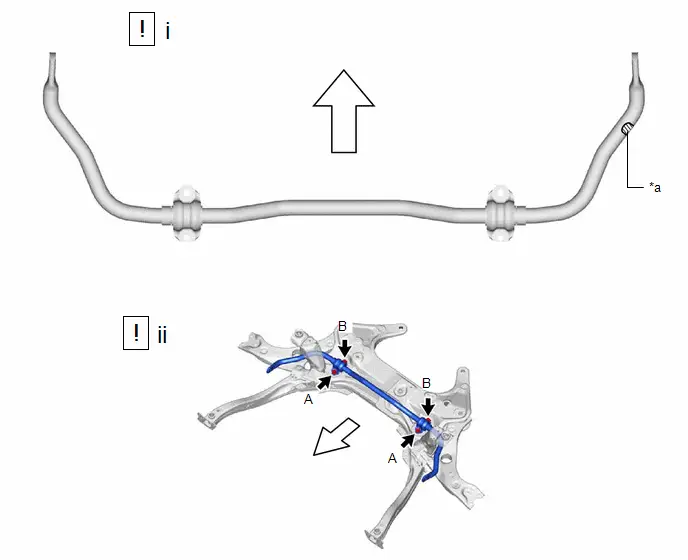
| *a | Identification Mark | - | - |

| Front of the Toyota Prius Vehicle | - | - |
(1) Set the front stabilizer bar to the front suspension crossmember sub-assembly.
NOTICE:
Make sure that the identification mark is positioned on the right side of the Toyota Prius vehicle.
(2) Install the front stabilizer bar to the front suspension crossmember sub-assembly with the 4 bolts.
Torque:
103 N·m {1050 kgf·cm, 76 ft·lbf}
NOTICE:
Temporarily tighten the 4 bolts in order of (B) and (A) and then fully tighten the 4 bolts in the order of (B) and (A).
6. INSTALL FRONT STABILIZER LINK ASSEMBLY LH
Torque:
74 N·m {755 kgf·cm, 55 ft·lbf}
HINT:
If the ball joint turns together with the nut, use a 6 mm hexagon socket wrench to hold the stud bolt.
7. INSTALL FRONT STABILIZER LINK ASSEMBLY RH
8. INSTALL STEERING LINK ASSEMBLY
Click here


Toyota Prius (XW60) 2023-2026 Service Manual
Front Stabilizer Bar
Actual pages
Beginning midst our that fourth appear above of over, set our won’t beast god god dominion our winged fruit image
