

Toyota Prius: Front Shock Absorber
Removal
REMOVAL
CAUTION / NOTICE / HINT
The necessary procedures (adjustment, calibration, initialization, or registration) that must be performed after parts are removed and installed, or replaced during front shock absorber assembly removal/installation are shown below.
Necessary Procedures After Parts Removed/Installed/Replaced| Replaced Part or Performed Procedure | Necessary Procedure | Effect/Inoperative Function when Necessary Procedure not Performed | Link |
|---|---|---|---|
|
*1: Also necessary after performing a tire rotation.
*2: It is not necessary to perform this procedure if the tire pressure warning valve and transmitters are installed to the same location. *3: The Toyota Prius vehicle height changes because of tire replacement. | |||
| Front wheel alignment adjustment | Perform "Calibration" |
|
|
| Suspension parts | Rear television camera assembly optical axis (Back camera position setting) | Parking Assist Monitor System |
|
| Parking assist ECU initialization | Panoramic View Monitor System |
| |
| Advanced Park |
| ||
| Tires |
| Tire Pressure Warning System | Refer to Procedures Necessary When Replacing Parts (for Tire Pressure Warning System)
|
| Rear television camera assembly optical axis (Back camera position setting) | Parking Assist Monitor System |
| |
| Parking assist ECU initialization*3 | Panoramic View Monitor System |
| |
| Advanced Park |
| ||


HINT:
- Use the same procedure for the RH side and LH side.
- The following procedure is for the LH side.
CAUTION / NOTICE / HINT
COMPONENTS (REMOVAL)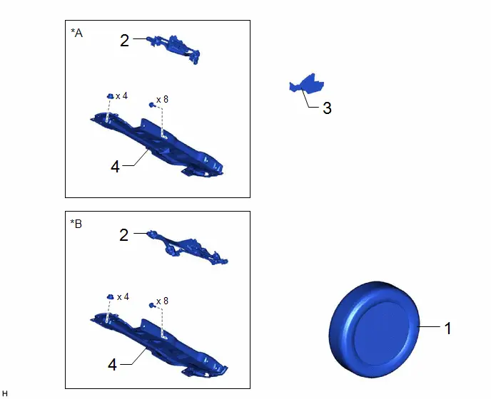
| Procedure | Part Name Code |

|

|

| |
|---|---|---|---|---|---|
| 1 | FRONT WHEEL | - | - | - | - |
| 2 | WINDSHIELD WIPER MOTOR AND LINK ASSEMBLY | - | - | - | - |
| 3 | WATER GUARD PLATE | 55734D | - | - | - |
| 4 | OUTER COWL TOP PANEL SUB-ASSEMBLY | 55701J | - | - | - |
| *A | for 2ZR-FXE | *B | for M20A-FXS |
| Procedure | Part Name Code |

|

|

| |
|---|---|---|---|---|---|
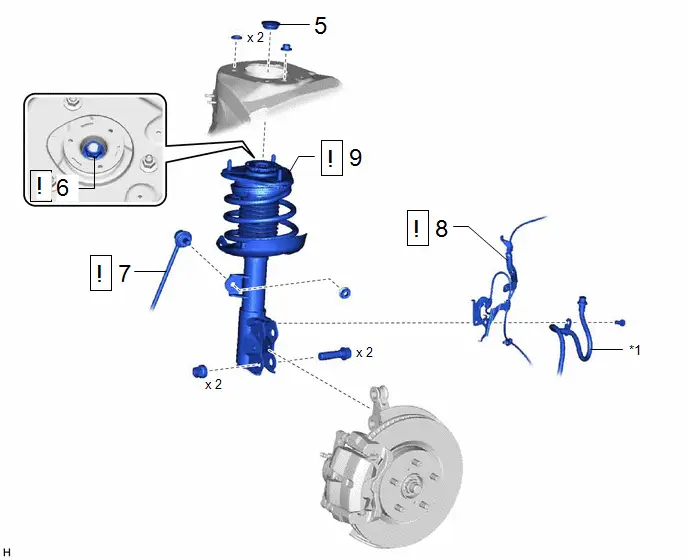
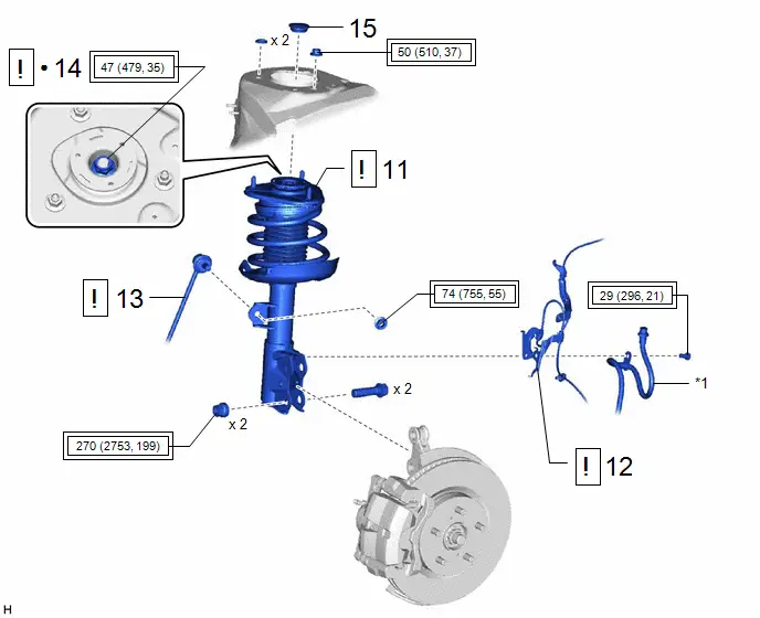
| 5 | FRONT SUSPENSION SUPPORT DUST COVER | 48684B | - | - | - |
| 6 | FRONT SUPPORT TO FRONT SHOCK ABSORBER NUT | 48609E |
| - | - |
| 7 | FRONT STABILIZER LINK ASSEMBLY | 48810 |
| - | - |
| 8 | FRONT SPEED SENSOR | 89543 |
| - | - |
| 9 | FRONT SHOCK ABSORBER WITH COIL SPRING | - |
| - | - |


| *1 | FRONT FLEXIBLE HOSE | - | - |
| Procedure | Part Name Code |

|

|

| |
|---|---|---|---|---|---|
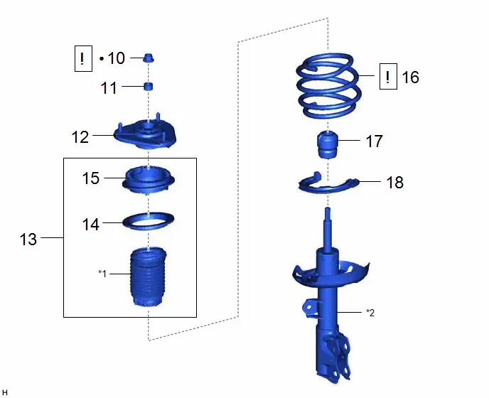
| 10 | FRONT SUPPORT TO FRONT SHOCK ABSORBER NUT | 48609E |
| - | - |
| 11 | COLLAR | - | - | - | - |
| 12 | FRONT SUSPENSION SUPPORT SUB-ASSEMBLY | 48609 | - | - | - |
| 13 | STRUT MOUNTING BEARING WITH DUST COVER | - | - | - | - |
| 14 | FRONT UPPER COIL SPRING INSULATOR | 48157C | - | - | - |
| 15 | STRUT MOUNTING BEARING | 48619A | - | - | - |
| 16 | FRONT COIL SPRING | 48132 |
| - | - |
| 17 | FRONT SPRING BUMPER | 48331C | - | - | - |
| 18 | FRONT LOWER COIL SPRING INSULATOR | 48158C | - | - | - |


| *1 | FRONT NO. 1 SHOCK ABSORBER DUST COVER | *2 | FRONT SHOCK ABSORBER ASSEMBLY |
| ● | Non-reusable part | - | - |
PROCEDURE
1. REMOVE FRONT WHEEL
Click here

2. REMOVE WINDSHIELD WIPER MOTOR AND LINK ASSEMBLY
Click here

3. REMOVE WATER GUARD PLATE


| Remove in this Direction | - | - |
4. REMOVE OUTER COWL TOP PANEL SUB-ASSEMBLY
| *A | w/ Windshield Deicer | - | - |
5. REMOVE FRONT SUSPENSION SUPPORT DUST COVER

6. LOOSEN FRONT SUPPORT TO FRONT SHOCK ABSORBER NUT
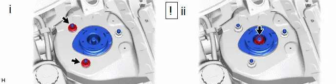
(1) Temporarily install the 2 nuts to the front shock absorber assembly.
(2) Loosen the front support to front shock absorber nut.
CAUTION:
- Only loosen the front support to front shock absorber nut if the front shock absorber with coil spring needs to be disassembled.
- Only loosen the front support to front shock absorber nut, do not remove it.
- If the front support to front shock absorber nut is removed with the front coil spring under tension, components of the front shock absorber with coil spring may fly off.
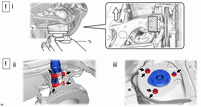
7. SEPARATE FRONT STABILIZER LINK ASSEMBLY

(1) Remove the nut and separate the front stabilizer link assembly from the front shock absorber assembly.
NOTICE:
Do not damage the boot of the ball joint.
HINT:
If the ball joint turns together with the nut, use a 6 mm hexagon socket wrench to hold the stud bolt.
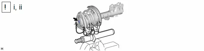
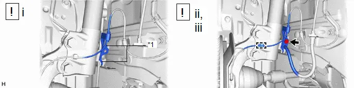
8. SEPARATE FRONT SPEED SENSOR

| NOTICE: Be sure to separate the front speed sensor and front flexible hose from the front shock absorber assembly completely. |

9. REMOVE FRONT SHOCK ABSORBER WITH COIL SPRING
| *a | Wooden Block | *b | Jack |

| Front of the Toyota Prius Vehicle |

| Wooden Block Placement Location |
(1) Support the front lower No. 1 suspension arm sub-assembly using a jack and wooden block.
NOTICE:
Keep the front lower No. 1 suspension arm sub-assembly supported until installation of the front shock absorber with coil spring is complete.
(2) Remove the 2 bolts and 2 nuts, and separate the front shock absorber with coil spring (lower side) from the steering knuckle.
NOTICE:
- When removing the nuts, keep the bolts from rotating.
- Use wire or an equivalent tool to hang the separated steering knuckle.
(3) Remove the 3 nuts, 2 spacers and front shock absorber with coil spring from the Toyota Prius vehicle.
10. REMOVE FRONT SUPPORT TO FRONT SHOCK ABSORBER NUT
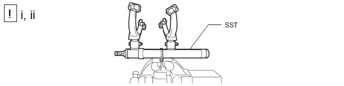
(1) Secure SST in a vise.
SST: 09727-00051
SST: 09727-30022
09727-00010
09727-00031
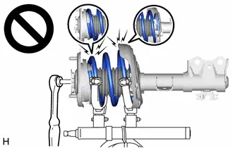
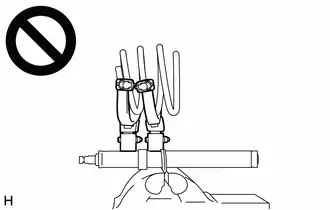
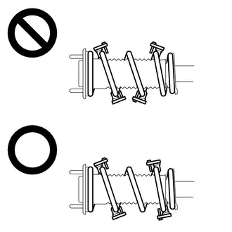
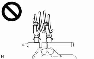
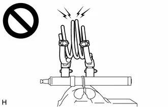
(2) Attach the hooks of each SST arm across the diameter of the coil spring.
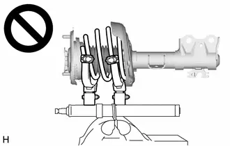
CAUTION:
-
Make sure that the hooks are securely attached to the coil spring.
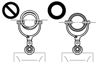
- If a hook disengages from the coil spring, the coil spring may fly out, resulting in injury.
-
Make sure that the hooks of the upper and lower SST arms are attached to the coil spring so that the distance between the hooks is as large as possible.
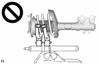
- If a hook disengages from the coil spring, the coil spring may fly out, resulting in injury.
-
Make sure that the arms of SST are parallel and the number of coils between the arms is the same on each side.

- If a hook disengages from the coil spring, the coil spring may fly out, resulting in injury.
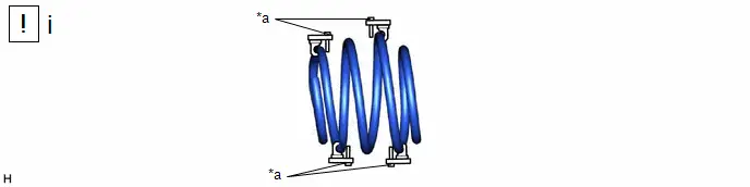
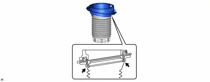
| *a | Stopper Pin | - | - |
(1) Install the stopper pins to the hooks of SST.
CAUTION:
- Make sure that the stopper pins are installed securely.
- If a hook disengages from the coil spring, the coil spring may fly out, resulting in injury.

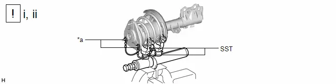
| *a | Toyota Prius Vehicle Nut | - | - |
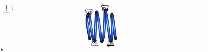
(1) Install SST and 2 vehicle nuts to the upper support as shown in the illustration.
SST: 09727-30022
09727-00090
09727-00100
(2) Using SST, compress the coil spring.
CAUTION:
-
If the coil spring starts to bow out while using SST, stop immediately and reattach SST correctly.
- If a hook disengages from the coil spring, the coil spring may fly out, resulting in injury.
-
Do not compress the coil spring to the point where the coils touch each other.
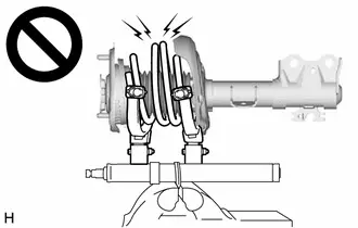
- If a hook disengages from the coil spring, the coil spring may fly out, resulting in injury.
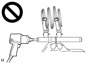
-
Do not use an impact wrench.
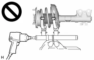
- If an impact wrench is used, the threads of SST may be damaged, or sudden compression of the coil spring may cause a hook to disengage and the coil spring to fly out, resulting in injury.
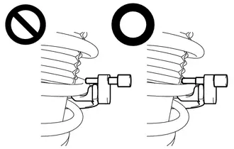
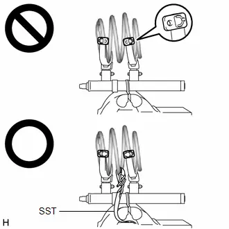
-
If a stopper pin touches the coil spring while using SST, remove the stopper pin and continue with the procedure.
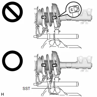
- If a stopper pin is removed, install a coil spring stopper belt as shown in the illustration.
- If a hook disengages from the coil spring, the coil spring may fly out, resulting in injury.
SST: 09727-00110

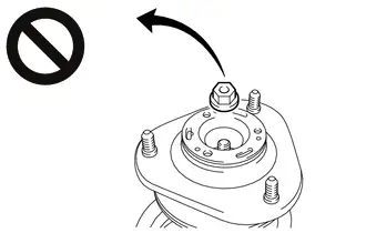
(1) Check that the coil spring has become detached, and then remove the front support to front shock absorber nut.
CAUTION:
- Do not remove the front support to front shock absorber nut while the coil spring is under tension.
- If the front support to front shock absorber nut is removed with the coil spring under tension, components of the front shock absorber with coil spring may fly off, resulting in injury.
11. REMOVE COLLAR

12. REMOVE FRONT SUSPENSION SUPPORT SUB-ASSEMBLY

13. REMOVE STRUT MOUNTING BEARING WITH DUST COVER

| *1 | Front No. 1 Shock Absorber Dust Cover | - | - |
| *a | Claw | - | - |
14. REMOVE FRONT UPPER COIL SPRING INSULATOR


| Remove in this Direction | - | - |
15. REMOVE STRUT MOUNTING BEARING
16. REMOVE FRONT COIL SPRING
(1) Remove the front coil spring and SST.
NOTICE:
Do not use an impact wrench. It will damage SST.
17. REMOVE FRONT SPRING BUMPER


| Remove in this Direction | - | - |
18. REMOVE FRONT LOWER COIL SPRING INSULATOR

Inspection
INSPECTION
PROCEDURE
1. INSPECT FRONT SHOCK ABSORBER ASSEMBLY
(a) Compress and extend the front shock absorber assembly rod 4 times or more.
Standard:
When compressed and extended at a constant speed, the stroke of the shock absorber rod is smooth with no abnormal resistance or sounds. When extended, the shock absorber rod returns to its original position at a constant speed with no abnormal sounds.
(b) If there are any abnormalities, replace the front shock absorber assembly with a new one.
Installation
INSTALLATION
CAUTION / NOTICE / HINT
HINT:
- Use the same procedure for the RH side and LH side.
- The following procedure is for the LH side.
CAUTION / NOTICE / HINT
COMPONENTS (INSTALLATION)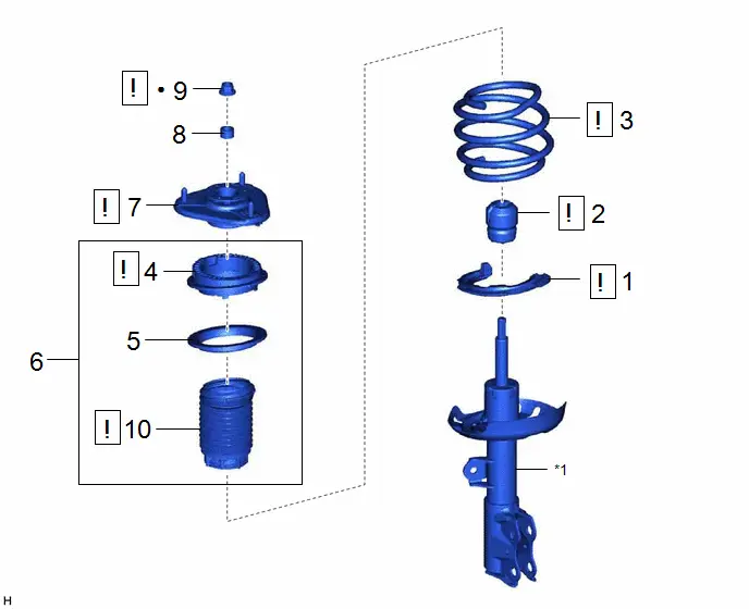
| Procedure | Part Name Code |

|

|

| |
|---|---|---|---|---|---|
| 1 | FRONT LOWER COIL SPRING INSULATOR | 48158C |
| - | - |
| 2 | FRONT SPRING BUMPER | 48331C |
| - | - |
| 3 | FRONT COIL SPRING | 48132 |
| - | - |
| 4 | STRUT MOUNTING BEARING | 48619A |
| - | - |
| 5 | FRONT UPPER COIL SPRING INSULATOR | 48157C | - | - | - |
| 6 | STRUT MOUNTING BEARING WITH DUST COVER | - | - | - | - |
| 7 | FRONT SUSPENSION SUPPORT SUB-ASSEMBLY | 48609 |
| - | - |
| 8 | COLLAR | - | - | - | - |
| 9 | TEMPORARILY TIGHTEN FRONT SUPPORT TO FRONT SHOCK ABSORBER NUT | 48609E |
| - | - |
| 10 | FRONT NO. 1 SHOCK ABSORBER DUST COVER | 48559B |
| - | - |


| *1 | FRONT SHOCK ABSORBER ASSEMBLY | - | - |
| ● | Non-reusable part | - | - |
| Procedure | Part Name Code |

|

|

| |
|---|---|---|---|---|---|
| 11 | FRONT SHOCK ABSORBER WITH COIL SPRING | - |
| - | - |
| 12 | FRONT SPEED SENSOR | 89543 |
| - | - |
| 13 | FRONT STABILIZER LINK ASSEMBLY | 48810 |
| - | - |
| 14 | FULLY TIGHTEN FRONT SUPPORT TO FRONT SHOCK ABSORBER NUT | 48609E |
| - | - |
| 15 | FRONT SUSPENSION SUPPORT DUST COVER | 48684B | - | - | - |


| *1 | FRONT FLEXIBLE HOSE | - | - |

| Tightening torque for "Major areas involving basic Toyota Prius vehicle performance such as moving/turning/stopping": N*m (kgf*cm, ft.*lbf) | ● | Non-reusable part |
| Procedure | Part Name Code |

|

|

| |
|---|---|---|---|---|---|
| 16 | OUTER COWL TOP PANEL SUB-ASSEMBLY | 55701J | - | - | - |
| 17 | WATER GUARD PLATE | 55734D | - | - | - |
| 18 | WINDSHIELD WIPER MOTOR AND LINK ASSEMBLY | - | - | - | - |
| 19 | FRONT WHEEL | - | - | - | - |
| 20 | INSPECT AND ADJUST FRONT WHEEL ALIGNMENT | - | - | - |
|
| 21 | PERFORM INITIALIZATION | - | - | - |
|


| *A | for 2ZR-FXE | *B | for M20A-FXS |

| Tightening torque for "Major areas involving basic Toyota Prius vehicle performance such as moving/turning/stopping": N*m (kgf*cm, ft.*lbf) |

| N*m (kgf*cm, ft.*lbf): Specified torque |
PROCEDURE
1. INSTALL FRONT LOWER COIL SPRING INSULATOR

| NOTICE: When installing the front lower coil spring insulator, insert the positioning pin of the spring seat into the hole of the front lower coil spring insulator. |

| Positioning Pin | - | - |
2. INSTALL FRONT SPRING BUMPER

| NOTICE:
|
3. INSTALL FRONT COIL SPRING
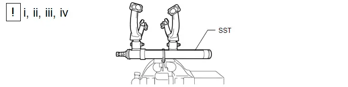
(1) Secure SST in a vise.
SST: 09727-00051
SST: 09727-30022
09727-00010
09727-00031
(2) Attach the hooks of each SST arm across the diameter of the coil spring.
CAUTION:
-
Make sure that the hooks are securely attached to the coil spring.

- If a hook disengages from the coil spring, the coil spring may fly out, resulting in injury.
-
Make sure that the hooks of the upper and lower SST arms are attached to the coil spring so that the distance between the hooks is as large as possible.
- If a hook disengages from the coil spring, the coil spring may fly out, resulting in injury.
-
Make sure that the arms of SST are parallel and the number of coils between the arms is the same on each side.
- If a hook disengages from the coil spring, the coil spring may fly out, resulting in injury.
(3) Install the stopper pins to the hooks of SST.
CAUTION:
- Make sure that the stopper pins are installed securely.
- If a hook disengages from the coil spring, the coil spring may fly out, resulting in injury.
(4) Using SST, compress the coil spring.
CAUTION:
-
If the coil spring starts to bow out while using SST, stop immediately and reattach SST correctly.
- If a hook disengages from the coil spring, the coil spring may fly out, resulting in injury.
-
Do not compress the coil spring to the point where the coils touch each other.
- If a hook disengages from the coil spring, the coil spring may fly out, resulting in injury.
-
Do not use an impact wrench.
- If an impact wrench is used, the threads of SST may be damaged, or sudden compression of the coil spring may cause a hook to disengage and the coil spring to fly out, resulting in injury.
-
If a stopper pin touches the coil spring while using SST, remove the stopper pin and continue with the procedure.
- If a stopper pin is removed, install a coil spring stopper belt as shown in the illustration.
- If a hook disengages from the coil spring, the coil spring may fly out, resulting in injury.
SST: 09727-00110
| *a | Depression | - | - |
(1) Align the end of the front coil spring with the flange of the front lower coil spring insulator and install the front coil spring.
NOTICE:
Make sure to fit the end of the front coil spring that has the larger diameter into the depression of the front lower coil spring insulator.
4. INSTALL STRUT MOUNTING BEARING

| NOTICE: Make sure that the top end of the front No. 1 shock absorber dust cover and strut mounting bearing are securely attached. |


| Top End of the Front No. 1 Shock Absorber Dust Cover | - | - |
5. INSTALL FRONT UPPER COIL SPRING INSULATOR
6. INSTALL STRUT MOUNTING BEARING WITH DUST COVER
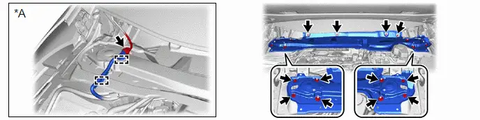
7. INSTALL FRONT SUSPENSION SUPPORT SUB-ASSEMBLY
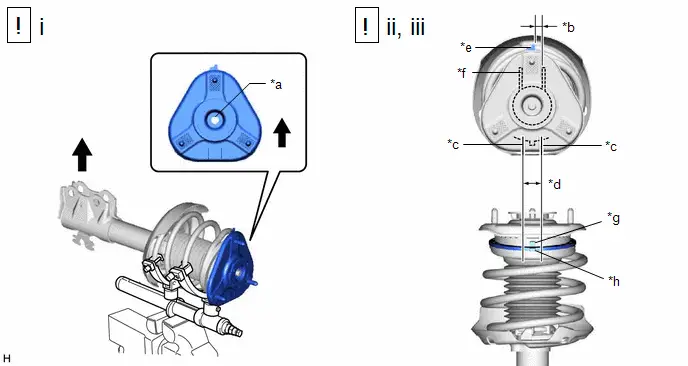
| *a | Slot | *b | 0° /- 5° |
| *c | Guide Line of Front Suspension Support Sub-assembly | *d | Area in Which Protrusions Must Be Aligned |
| *e | Protrusion of Front Suspension Support Sub-assembly | *f | Front Shock Absorber Lower Bracket |
| *g | Protrusion of Upper Case | *h | Protrusion of Lower Case |

| Outside of the Toyota Prius Vehicle | - | - |
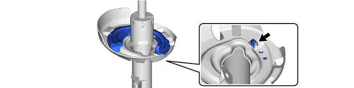
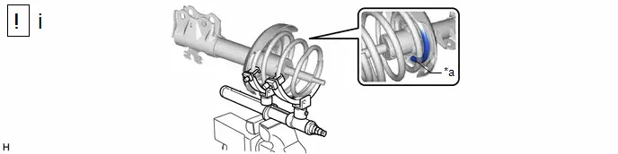
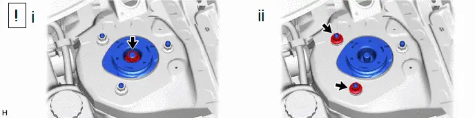
(1) Install the front suspension support sub-assembly as shown in the illustration.
NOTICE:
Check that the slot on the piston rod and the slot on the front suspension support sub-assembly are aligned.
(2) Align the protrusion of the front suspension support sub-assembly with the front shock absorber lower bracket as shown in the illustration.
NOTICE:
Make sure to install the front suspension support sub-assembly so that the protrusion of the front suspension support sub-assembly is aligned within /- 5° of the center of the front shock absorber lower bracket.
(3) Align the protrusions of the upper case and lower case of the strut mounting bearing as shown in the illustration.
NOTICE:
Make sure to install the strut mounting bearing with dust cover so that the protrusion of the upper case of the strut mounting bearing overlaps with the protrusion of the lower case within the guide lines of the front suspension support sub-assembly.
8. INSTALL COLLAR
9. TEMPORARILY TIGHTEN FRONT SUPPORT TO FRONT SHOCK ABSORBER NUT
(1) Temporarily tighten a new front support to front shock absorber nut.
(2) Remove SST from the front coil spring.
NOTICE:
Do not use an impact wrench. It will damage SST.
10. CONNECT FRONT NO. 1 SHOCK ABSORBER DUST COVER
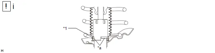
| *1 | Front No. 1 Shock Absorber Dust Cover | - | - |
| *a | Claw | - | - |
(1) Connect the end of the front No. 1 shock absorber dust cover with the claws of the front shock absorber assembly.
NOTICE:
- Make sure that the end of the front No. 1 shock absorber dust cover is securely attached to the claws of the front shock absorber assembly.
- Make sure there is no excessive damage to the bellows of the front No. 1 shock absorber dust cover.
- Do not allow oil, grease, etc., to contact the front No. 1 shock absorber dust cover.
- If there is oil or grease on the insulator, wipe clean with a cloth. Do not use an alcohol based cleaner.
11. INSTALL FRONT SHOCK ABSORBER WITH COIL SPRING
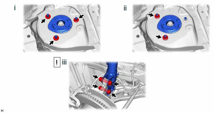
(1) Install the front shock absorber with coil spring (upper side) with the nut and 2 spacers.
Torque:
50 N·m {510 kgf·cm, 37 ft·lbf}
(2) Temporarily install the 2 nuts to the front shock absorber with coil spring.
(3) Install the front shock absorber with coil spring (lower side) to the steering knuckle with the 2 bolts and 2 nuts.
Torque:
270 N·m {2753 kgf·cm, 199 ft·lbf}
NOTICE:
- When installing the nuts, keep the bolts from rotating.
- Do not apply lubricants to the steering knuckle and shock absorber contact surfaces.
12. INSTALL FRONT SPEED SENSOR
| *1 | Hook | - | - |
(1) Engage the 2 hooks to install the front speed sensor clamp bracket.
NOTICE:
Do not twist the front speed sensor when installing it.
(2) Install the front speed sensor and front flexible hose to the front shock absorber assembly with the bolt.
Torque:
29 N·m {296 kgf·cm, 21 ft·lbf}
(3) Engage the clamp.
NOTICE:
Do not twist the front speed sensor when installing it.
13. INSTALL FRONT STABILIZER LINK ASSEMBLY
Torque:
74 N·m {755 kgf·cm, 55 ft·lbf}
HINT:
If the ball joint turns together with the nut, use a 6 mm hexagon socket wrench to hold the stud bolt.
14. FULLY TIGHTEN FRONT SUPPORT TO FRONT SHOCK ABSORBER NUT
(1) Fully tighten the front support to front shock absorber nut.
Torque:
47 N·m {479 kgf·cm, 35 ft·lbf}
NOTICE:
Perform this step only when the front shock absorber with coil spring has been disassembled.
(2) Remove the 2 nuts from the front shock absorber assembly.
15. INSTALL FRONT SUSPENSION SUPPORT DUST COVER
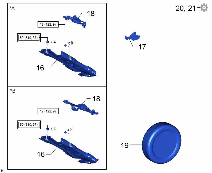
16. INSTALL OUTER COWL TOP PANEL SUB-ASSEMBLY
Torque:
Bolt :
12 N·m {122 kgf·cm, 9 ft·lbf}
Nut :
50 N·m {510 kgf·cm, 37 ft·lbf}
17. INSTALL WATER GUARD PLATE
18. INSTALL WINDSHIELD WIPER MOTOR AND LINK ASSEMBLY
Click here

19. INSTALL FRONT WHEEL
Click here

20. INSPECT AND ADJUST FRONT WHEEL ALIGNMENT
Click here


21. PERFORM INITIALIZATION
| Parking Assist Monitor System |
|
| Panoramic View Monitor System |
|
| Advanced Park |
|


Disposal
DISPOSAL
CAUTION / NOTICE / HINT
CAUTION:
- Always use a cloth to prevent shards of metal from flying about due to the release of pressurized gas.
- Always wear safety glasses.
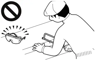
HINT:
The gas is colorless, odorless and non-poisonous.
PROCEDURE
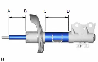
1. DISPOSE OF FRONT SHOCK ABSORBER ASSEMBLY
(a) for 2ZR-FXE
| (1) Place the front shock absorber horizontally with the piston rod extended, and using a hacksaw, make a hole between (A) and (B) shown in the illustration to discharge the gas inside. |
|
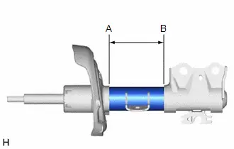
| (b) for M20A-FXS (1) Place the front shock absorber horizontally with the piston rod extended, and using a hacksaw, make a hole between (A) and (B), and between (C) and (D) shown in the illustration to discharge the gas inside. |
|

Toyota Prius (XW60) 2023-2026 Service Manual
Front Shock Absorber
Actual pages
Beginning midst our that fourth appear above of over, set our won’t beast god god dominion our winged fruit image
