

Toyota Prius: Front Suspension Member
Removal
REMOVAL
CAUTION / NOTICE / HINT
The necessary procedures (adjustment, calibration, initialization, or registration) that must be performed after parts are removed and installed, or replaced during front suspension crossmember sub-assembly removal/installation are shown below.
Necessary Procedures After Parts Removed/Installed/Replaced| Replaced Part or Performed Procedure | Necessary Procedure | Effect/Inoperative Function when Necessary Procedure not Performed | Link |
|---|---|---|---|
|
*: Even when not replacing the part, it is necessary to perform the specified necessary procedures after installation.
*1: Also necessary after performing a tire rotation. *2: It is not necessary to perform this procedure if the tire pressure warning valve and transmitters are installed to the same location. *3: The Toyota Prius vehicle height changes because of tire replacement. *4: If matchmarks were not placed when removing parts related to steering operation, perform end position initial setting. | |||
| Front wheel alignment adjustment | Perform "Calibration" |
|
|
| Suspension parts | Rear television camera assembly optical axis (Back camera position setting) | Parking Assist Monitor System |
|
| Parking assist ECU initialization | Panoramic View Monitor System |
| |
| Advanced Park |
| ||
| Tires |
| Tire Pressure Warning System | Refer to Procedures Necessary When Replacing Parts (for Tire Pressure Warning System)
|
| Rear television camera assembly optical axis (Back camera position setting) | Parking Assist Monitor System |
| |
| Parking assist ECU initialization*3 | Panoramic View Monitor System |
| |
| Advanced Park |
| ||
| End position initial setting | - |
|
| Front bumper assembly* | Front television camera view adjustment | Panoramic View Monitor System |
|
| Advanced Park |
| ||


CAUTION / NOTICE / HINT
COMPONENTS (REMOVAL)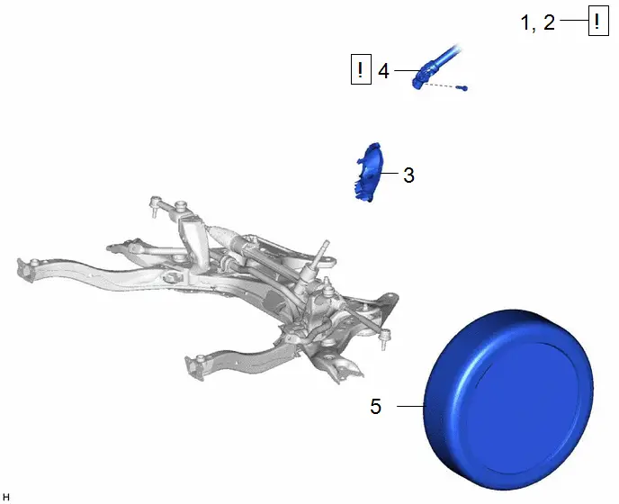
| Procedure | Part Name Code |

|

|

| |
|---|---|---|---|---|---|
| 1 | ALIGN FRONT WHEELS FACING STRAIGHT AHEAD | - |
| - | - |
| 2 | SECURE STEERING WHEEL | - |
| - | - |
| 3 | COLUMN HOLE COVER SILENCER SHEET | 45259A | - | - | - |
| 4 | NO. 2 STEERING INTERMEDIATE SHAFT ASSEMBLY | 45260 |
| - | - |
| 5 | FRONT WHEELS | - | - | - | - |


| Procedure | Part Name Code |

|

|

| |
|---|---|---|---|---|---|
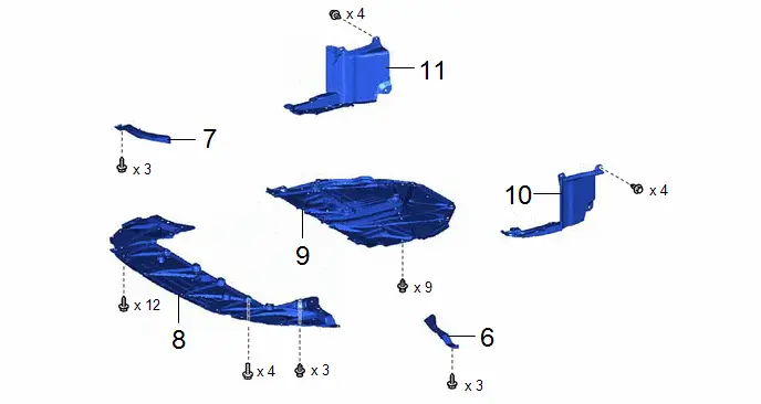
| 6 | FRONT WHEEL OPENING EXTENSION PAD LH | 53852B | - | - | - |
| 7 | FRONT WHEEL OPENING EXTENSION PAD RH | 53851D | - | - | - |
| 8 | CENTER ENGINE UNDER COVER | 51451A | - | - | - |
| 9 | NO. 1 ENGINE UNDER COVER ASSEMBLY | 51410 | - | - | - |
| 10 | REAR ENGINE UNDER COVER LH | 51444A | - | - | - |
| 11 | REAR ENGINE UNDER COVER RH | 51443C | - | - | - |

| Procedure | Part Name Code |

|

|

| |
|---|---|---|---|---|---|
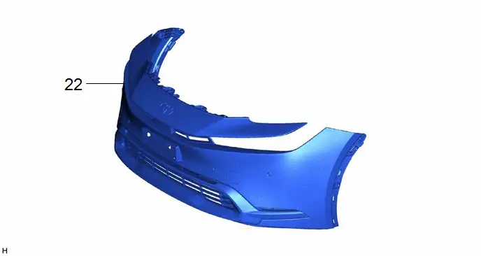
| 12 | FRONT BUMPER ASSEMBLY | - | - | - | - |
| Procedure | Part Name Code |

|

|

| |
|---|---|---|---|---|---|
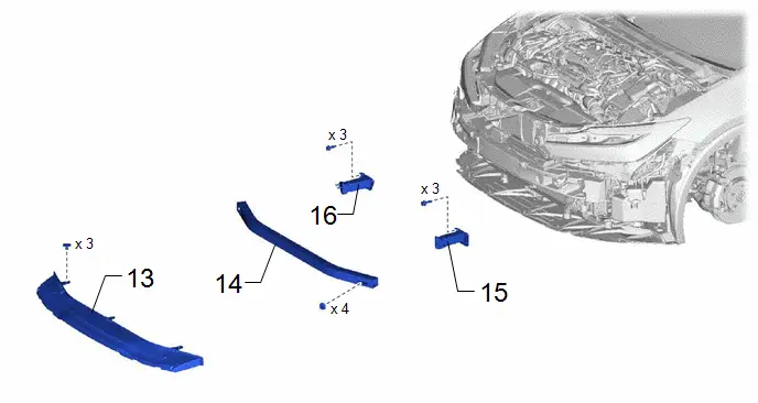
| 13 | FRONT BUMPER LOWER ABSORBER | 52618 | - | - | - |
| 14 | NO. 2 FRONT BUMPER REINFORCEMENT | 52132A | - | - | - |
| 15 | FRONT BUMPER EXTENSION SUB-ASSEMBLY LH | 52103A | - | - | - |
| 16 | FRONT BUMPER EXTENSION SUB-ASSEMBLY RH | 52102B | - | - | - |
| Procedure | Part Name Code |

|

|

| |
|---|---|---|---|---|---|
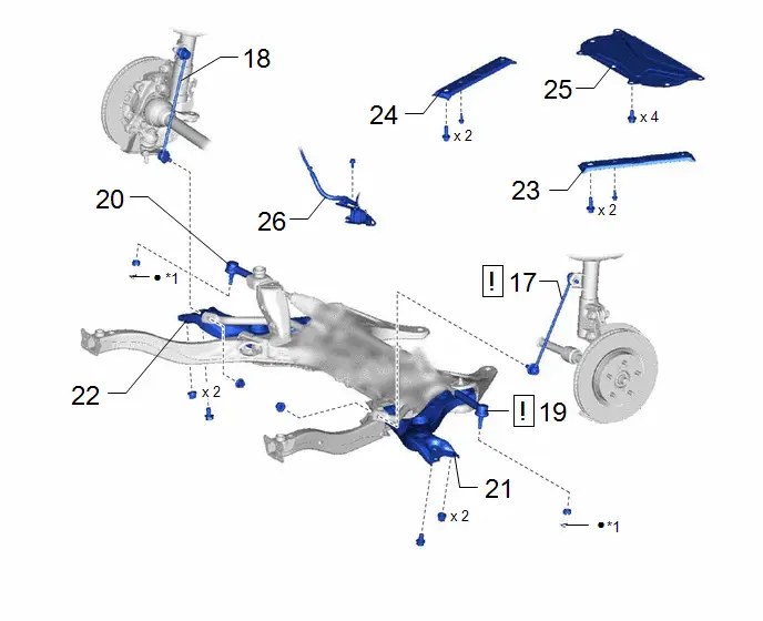
| 17 | FRONT STABILIZER LINK ASSEMBLY LH | 48810 |
| - | - |
| 18 | FRONT STABILIZER LINK ASSEMBLY RH | 48820B | - | - | - |
| 19 | TIE ROD END SUB-ASSEMBLY LH | 45047 |
| - | - |
| 20 | TIE ROD END SUB-ASSEMBLY RH | 45046 | - | - | - |
| 21 | FRONT LOWER NO. 1 SUSPENSION ARM SUB-ASSEMBLY LH | 48069 | - | - | - |
| 22 | FRONT LOWER NO. 1 SUSPENSION ARM SUB-ASSEMBLY RH | 48068 | - | - | - |
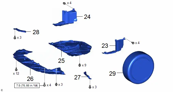
| 23 | NO. 2 CROSSMEMBER GUSSET LH | 51322 | - | - | - |
| 24 | NO. 2 CROSSMEMBER GUSSET RH | 51321 | - | - | - |
| 25 | NO. 2 ENGINE UNDER COVER | 51442 | - | - | - |
| 26 | WIRE HARNESS CLAMP BRACKET | - | - | - | - |


| *1 | COTTER PIN | - | - |
| ● | Non-reusable part | - | - |
| Procedure | Part Name Code |

|

|

| |
|---|---|---|---|---|---|
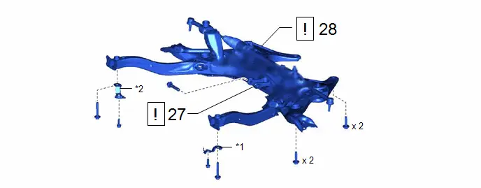
| 27 | ENGINE MOVING CONTROL ROD | 12363A |
| - | - |
| 28 | FRONT SUSPENSION CROSSMEMBER SUB-ASSEMBLY | 51201 |
| - | - |


| *1 | CENTER RADIATOR SUPPORT LH | *2 | CENTER RADIATOR SUPPORT RH |
| Procedure | Part Name Code |

|

|

| |
|---|---|---|---|---|---|
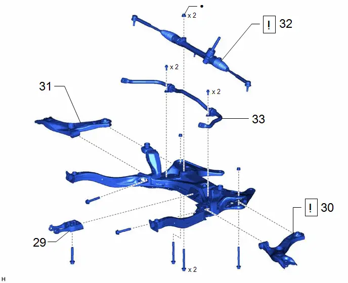
| 29 | ENGINE MOVING CONTROL ROD | 12363A | - | - | - |
| 30 | FRONT LOWER NO. 1 SUSPENSION ARM SUB-ASSEMBLY LH | 48069 |
| - | - |
| 31 | FRONT LOWER NO. 1 SUSPENSION ARM SUB-ASSEMBLY RH | 48068 | - | - | - |
| 32 | STEERING LINK ASSEMBLY | - |
| - | - |
| 33 | FRONT STABILIZER BAR | 48811 | - | - | - |


| ● | Non-reusable part | - | - |
PROCEDURE
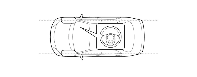
1. ALIGN FRONT WHEELS FACING STRAIGHT AHEAD
2. SECURE STEERING WHEEL
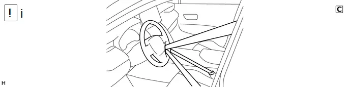
(1) Secure the steering wheel with the seat belt in order to prevent rotation.
HINT:
This operation is useful to prevent damage to the spiral cable.
3. REMOVE COLUMN HOLE COVER SILENCER SHEET
Click here

4. DISCONNECT NO. 2 STEERING INTERMEDIATE SHAFT ASSEMBLY

| Click here
|

5. REMOVE FRONT WHEELS
Click here

6. REMOVE FRONT WHEEL OPENING EXTENSION PAD LH
for M20A-FXS HEV Model: Click here

for M20A-FXS PHEV Model: Click here

for 2ZR-FXE: Click here

7. REMOVE FRONT WHEEL OPENING EXTENSION PAD RH
for M20A-FXS HEV Model: Click here

for M20A-FXS PHEV Model: Click here

for 2ZR-FXE: Click here

8. REMOVE CENTER ENGINE UNDER COVER
for M20A-FXS HEV Model: Click here

for M20A-FXS PHEV Model: Click here

for 2ZR-FXE: Click here

9. REMOVE NO. 1 ENGINE UNDER COVER ASSEMBLY
for M20A-FXS HEV Model: Click here

for M20A-FXS PHEV Model: Click here

for 2ZR-FXE: Click here

10. REMOVE REAR ENGINE UNDER COVER LH
for M20A-FXS HEV Model: Click here

for M20A-FXS PHEV Model: Click here

for 2ZR-FXE: Click here

11. REMOVE REAR ENGINE UNDER COVER RH
for M20A-FXS HEV Model: Click here

for M20A-FXS PHEV Model: Click here

for 2ZR-FXE: Click here

12. REMOVE FRONT BUMPER ASSEMBLY
Click here

13. REMOVE FRONT BUMPER LOWER ABSORBER
Click here

14. REMOVE NO. 2 FRONT BUMPER REINFORCEMENT
Click here

15. REMOVE FRONT BUMPER EXTENSION SUB-ASSEMBLY LH
for M20A-FXS HEV Model: Click here

for M20A-FXS PHEV Model: Click here

for 2ZR-FXE: Click here

16. REMOVE FRONT BUMPER EXTENSION SUB-ASSEMBLY RH
for M20A-FXS HEV Model: Click here

for M20A-FXS PHEV Model: Click here

for 2ZR-FXE: Click here

17. SEPARATE FRONT STABILIZER LINK ASSEMBLY LH
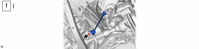
(1) Remove the nut and separate the front stabilizer link assembly LH from the front stabilizer bar.
NOTICE:
Do not damage the boot of the ball joint.
HINT:
If the ball joint turns together with the nut, use a 6 mm hexagon socket wrench to hold the stud bolt.
18. SEPARATE FRONT STABILIZER LINK ASSEMBLY RH
(a) Perform the same procedure as for the LH side.
19. SEPARATE TIE ROD END SUB-ASSEMBLY LH
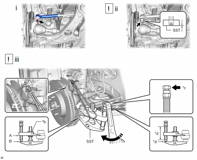
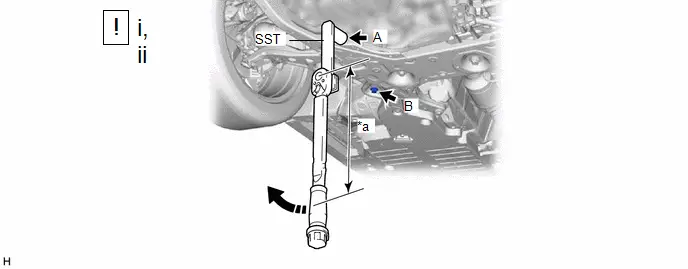
| *a | String | *b | Center Nut |
| *c | Place wrench here | *d | Molybdenum Grease Application Area |

| Turn | - | - |
(1) Remove the cotter pin and nut.
(2) Install SST to the tie rod end sub-assembly LH as shown in the illustration.
SST: 09960-20010
09961-02060
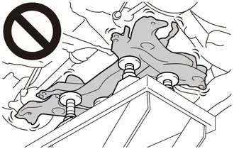
NOTICE:
Make sure that the lower ends of the tie rod end sub-assembly LH and SST are aligned.
(3) Using SST, separate the tie rod end sub-assembly LH from the steering knuckle LH as shown in the illustration.
SST: 09960-20010
09961-02010
09961-02060
CAUTION:
Apply molybdenum grease to the threads and end of the SST bolt.
NOTICE:
- Be sure to tighten the string firmly to secure SST to the steering knuckle LH to prevent SST from falling off.
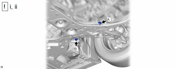
- Install SST with the center nut so that (A) and (B) shown in the illustration are parallel. Otherwise, the ball joint dust cover may be damaged.
- Be sure to place the wrench on the part shown in the illustration.
- Do not damage the front disc brake dust cover.
- Do not damage the ball joint dust cover.
- Do not damage the steering knuckle LH.
20. SEPARATE TIE ROD END SUB-ASSEMBLY RH
(a) Perform the same procedure as for the LH side.
21. SEPARATE FRONT LOWER NO. 1 SUSPENSION ARM SUB-ASSEMBLY LH
Click here

22. SEPARATE FRONT LOWER NO. 1 SUSPENSION ARM SUB-ASSEMBLY RH
(a) Perform the same procedure as for the LH side.
23. REMOVE NO. 2 CROSSMEMBER GUSSET LH
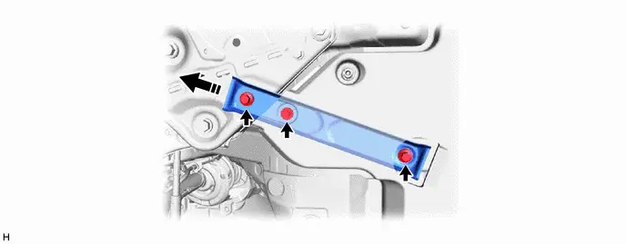

| Remove in this Direction | - | - |
24. REMOVE NO. 2 CROSSMEMBER GUSSET RH
(a) Perform the same procedure as for the LH side.
25. REMOVE NO. 2 ENGINE UNDER COVER
26. DISCONNECT WIRE HARNESS CLAMP BRACKET
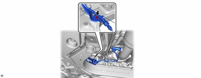
27. DISCONNECT ENGINE MOVING CONTROL ROD
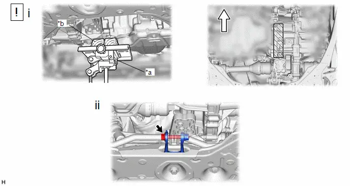
| *a | Transmission Jack | *b | Wooden Block |

| Front of the Toyota Prius Vehicle |

| Wooden block placement location |
(1) Using a transmission jack and a wooden block, support the engine assembly with transaxle.
CAUTION:
- Support the engine assembly with transaxle until the front suspension crossmember sub-assembly is installed.
- If the support is removed before the front suspension crossmember sub-assembly is installed, the engine assembly with transaxle may drop.
(2) Remove the bolt and separate the engine moving control rod.
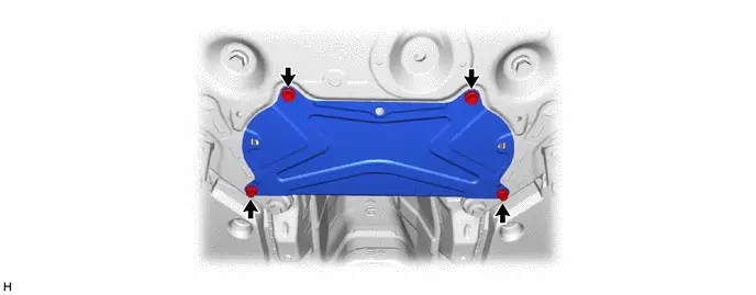
28. REMOVE FRONT SUSPENSION CROSSMEMBER SUB-ASSEMBLY
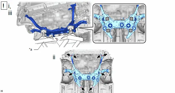
| *a | Engine Lifter | *b | Attachment |

| Attachment placement location | - | - |
(1) Support the front suspension crossmember sub-assembly with an engine lifter using 4 attachments or equivalent tools as shown in the illustration.
CAUTION:
-
The front suspension crossmember sub-assembly is a very heavy component. Make sure that it is supported securely.

- If the front suspension crossmember sub-assembly is not securely supported, it may drop, resulting in serious injury.
NOTICE:
Use attachments to keep the front suspension crossmember sub-assembly level.
(2) Remove the 8 bolts, center radiator support LH, center radiator support RH and front suspension crossmember sub-assembly from the Toyota Prius vehicle.
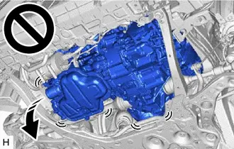
(3) Slowly lower the front suspension crossmember sub-assembly.
NOTICE:
- When lowering the front suspension crossmember sub-assembly, be careful not to damage the vehicle body or other components installed to the vehicle.
- Make sure that the front suspension crossmember sub-assembly not hit the protrusion of the reinforcement.
29. REMOVE ENGINE MOVING CONTROL ROD

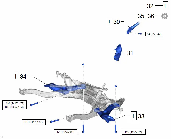
30. REMOVE FRONT LOWER NO. 1 SUSPENSION ARM SUB-ASSEMBLY LH

| NOTICE: Because the nut has its own stopper, do not turn the nut. Loosen the bolt with the nut secured. |

31. REMOVE FRONT LOWER NO. 1 SUSPENSION ARM SUB-ASSEMBLY RH
(a) Perform the same procedure as for the LH side.
32. REMOVE STEERING LINK ASSEMBLY

| Click here
|

33. REMOVE FRONT STABILIZER BAR
Click here

Installation
INSTALLATION
CAUTION / NOTICE / HINT
COMPONENTS (INSTALLATION)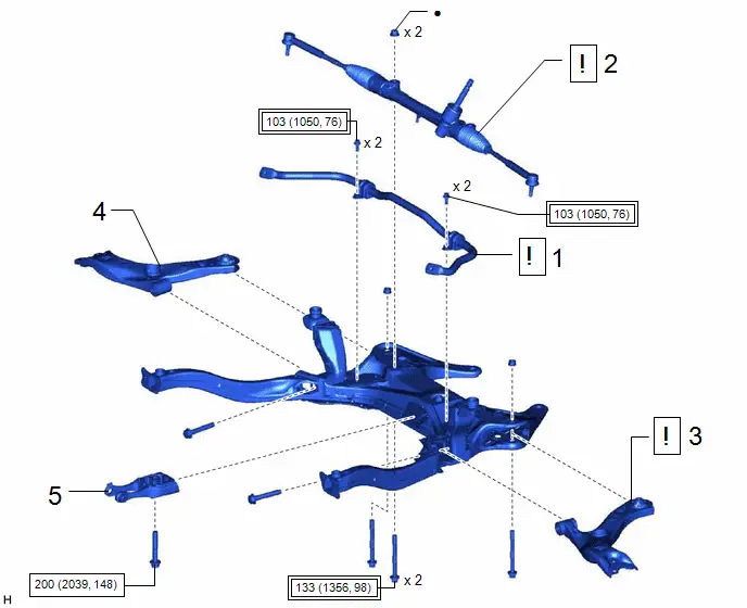
| Procedure | Part Name Code |

|

|

| |
|---|---|---|---|---|---|
| 1 | FRONT STABILIZER BAR | 48811 |
| - | - |
| 2 | STEERING LINK ASSEMBLY | - |
| - | - |
| 3 | TEMPORARILY INSTALL FRONT LOWER NO. 1 SUSPENSION ARM SUB-ASSEMBLY LH | 48069 |
| - | - |
| 4 | TEMPORARILY INSTALL FRONT LOWER NO. 1 SUSPENSION ARM SUB-ASSEMBLY RH | 48068 | - | - | - |
| 5 | INSTALL ENGINE MOVING CONTROL ROD | 12363A | - | - | - |


| Tightening torque for "Major areas involving basic Toyota Prius vehicle performance such as moving/turning/stopping" : N*m (kgf*cm, ft.*lbf) |

| N*m (kgf*cm, ft.*lbf): Specified torque |
| ● | Non-reusable part | - | - |
| Procedure | Part Name Code |

|

|

| |
|---|---|---|---|---|---|
| 6 | FRONT SUSPENSION CROSSMEMBER SUB-ASSEMBLY | 51201 |
| - | - |
| 7 | CONNECT ENGINE MOVING CONTROL ROD | 12363A | - | - | - |

| *1 | CENTER RADIATOR SUPPORT LH | *2 | CENTER RADIATOR SUPPORT RH |

| Tightening torque for "Major areas involving basic Toyota Prius vehicle performance such as moving/turning/stopping" : N*m (kgf*cm, ft.*lbf) |

| N*m (kgf*cm, ft.*lbf): Specified torque |
| Procedure | Part Name Code |

|

|

| |
|---|---|---|---|---|---|
| 8 | WIRE HARNESS CLAMP BRACKET | - | - | - | - |
| 9 | NO. 2 ENGINE UNDER COVER | 51442 | - | - | - |
| 10 | NO. 2 CROSSMEMBER GUSSET LH | 51322 | - | - | - |
| 11 | NO. 2 CROSSMEMBER GUSSET RH | 51321 | - | - | - |
| 12 | CONNECT FRONT LOWER NO. 1 SUSPENSION ARM SUB-ASSEMBLY LH | 48069 | - | - | - |
| 13 | CONNECT FRONT LOWER NO. 1 SUSPENSION ARM SUB-ASSEMBLY RH | 48068 | - | - | - |
| 14 | TIE ROD END SUB-ASSEMBLY LH | 45047 |
| - | - |
| 15 | TIE ROD END SUB-ASSEMBLY RH | 45046 | - | - | - |
| 16 | FRONT STABILIZER LINK ASSEMBLY LH | 48810 |
| - | - |
| 17 | FRONT STABILIZER LINK ASSEMBLY RH | 48820B | - | - | - |


| *1 | COTTER PIN | - | - |

| Tightening torque for "Major areas involving basic Toyota Prius vehicle performance such as moving/turning/stopping" : N*m (kgf*cm, ft.*lbf) |

| N*m (kgf*cm, ft.*lbf): Specified torque |
| ● | Non-reusable part | - | - |
| Procedure | Part Name Code |

|

|

| |
|---|---|---|---|---|---|
| 18 | FRONT BUMPER EXTENSION SUB-ASSEMBLY LH | 52103A | - | - | - |
| 19 | FRONT BUMPER EXTENSION SUB-ASSEMBLY RH | 52102B | - | - | - |
| 20 | NO. 2 FRONT BUMPER REINFORCEMENT | 52132A | - | - | - |
| 21 | FRONT BUMPER LOWER ABSORBER | 52618 | - | - | - |

| N*m (kgf*cm, ft.*lbf): Specified torque | - | - |
| Procedure | Part Name Code |

|

|

| |
|---|---|---|---|---|---|
| 22 | FRONT BUMPER ASSEMBLY | - | - | - | - |
| Procedure | Part Name Code |

|

|

| |
|---|---|---|---|---|---|
| 23 | REAR ENGINE UNDER COVER LH | 51444A | - | - | - |
| 24 | REAR ENGINE UNDER COVER RH | 51443C | - | - | - |
| 25 | NO. 1 ENGINE UNDER COVER ASSEMBLY | 51410 | - | - | - |
| 26 | CENTER ENGINE UNDER COVER | 51451A | - | - | - |
| 27 | FRONT WHEEL OPENING EXTENSION PAD LH | 53852B | - | - | - |
| 28 | FRONT WHEEL OPENING EXTENSION PAD RH | 53851D | - | - | - |
| 29 | FRONT WHEELS | - | - | - | - |

| N*m (kgf*cm, ft.*lbf): Specified torque | - | - |
| Procedure | Part Name Code |

|

|

| |
|---|---|---|---|---|---|
| 30 | NO. 2 STEERING INTERMEDIATE SHAFT ASSEMBLY | 45260 |
| - | - |
| 31 | COLUMN HOLE COVER SILENCER SHEET | 45259A | - | - | - |
| 32 | STABILIZE SUSPENSION | - |
| - | - |
| 33 | FULLY TIGHTEN FRONT LOWER NO. 1 SUSPENSION ARM SUB-ASSEMBLY LH | 48069 |
| - | - |
| 34 | FULLY TIGHTEN FRONT LOWER NO. 1 SUSPENSION ARM SUB-ASSEMBLY RH | 48068 |
| - | - |
| 35 | INSPECT AND ADJUST FRONT WHEEL ALIGNMENT | - | - | - |
|
| 36 | PERFORM INITIALIZATION | - | - | - |
|


| Tightening torque for "Major areas involving basic Toyota Prius vehicle performance such as moving/turning/stopping" : N*m (kgf*cm, ft.*lbf) | * | For use with SST |
PROCEDURE
1. INSTALL FRONT STABILIZER BAR

| Click here
|

2. INSTALL STEERING LINK ASSEMBLY

| Click here
|

3. TEMPORARILY INSTALL FRONT LOWER NO. 1 SUSPENSION ARM SUB-ASSEMBLY LH

| NOTICE: Because the nut has its own stopper, do not turn the nut. Tighten the bolt with the nut secured. |
4. TEMPORARILY INSTALL FRONT LOWER NO. 1 SUSPENSION ARM SUB-ASSEMBLY RH
5. INSTALL ENGINE MOVING CONTROL ROD
Torque:
200 N·m {2039 kgf·cm, 148 ft·lbf}
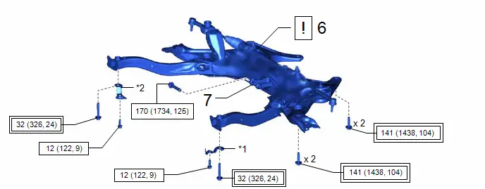
6. INSTALL FRONT SUSPENSION CROSSMEMBER SUB-ASSEMBLY
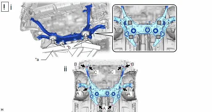
| *a | Engine Lifter | *b | Attachment |

| Attachment placement location | - | - |
(1) Slowly jack up the front suspension crossmember sub-assembly with an engine lifter using 4 attachments or equivalent tools.
CAUTION:
- The front suspension crossmember sub-assembly is a very heavy component. Make sure that it is supported securely.
- If the front suspension crossmember sub-assembly is not securely supported, it may drop, resulting in serious injury.
NOTICE:
- Use attachments to keep the front suspension crossmember sub-assembly level.
- Make sure that the front suspension crossmember sub-assembly not hit the protrusion of the reinforcement.
(2) Install the front suspension crossmember sub-assembly with the 8 bolts, center radiator support LH and center radiator support RH.
Torque:
Bolt (A) :
141 N·m {1438 kgf·cm, 104 ft·lbf}
Bolt (B) :
32 N·m {326 kgf·cm, 24 ft·lbf}
Bolt (C) :
12 N·m {122 kgf·cm, 9 ft·lbf}
7. CONNECT ENGINE MOVING CONTROL ROD
Torque:
170 N·m {1734 kgf·cm, 125 ft·lbf}
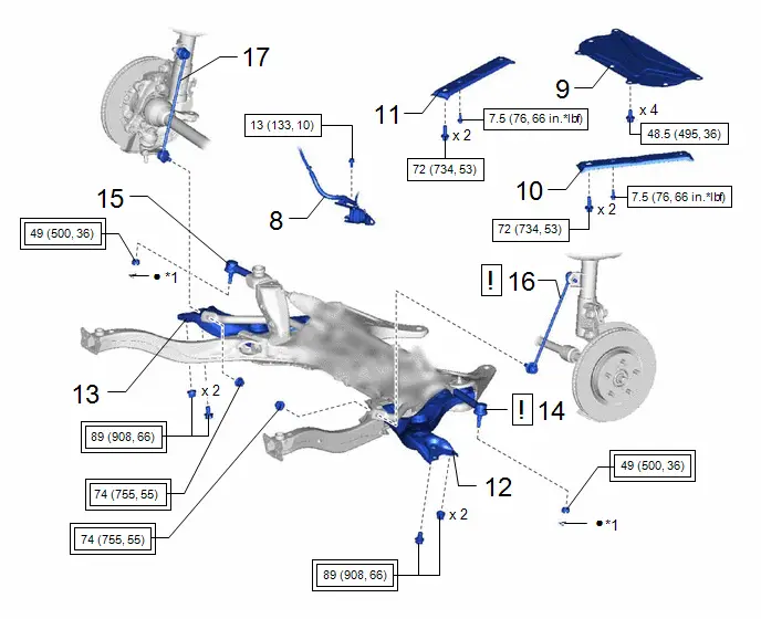
8. CONNECT WIRE HARNESS CLAMP BRACKET
Torque:
13 N·m {133 kgf·cm, 10 ft·lbf}
9. INSTALL NO. 2 ENGINE UNDER COVER
Torque:
48.5 N·m {495 kgf·cm, 36 ft·lbf}
10. INSTALL NO. 2 CROSSMEMBER GUSSET LH


| Install in this Direction | - | - |
Torque:
Bolt (A) :
72 N·m {734 kgf·cm, 53 ft·lbf}
Bolt (B) :
7.5 N·m {76 kgf·cm, 66 in·lbf}
11. INSTALL NO. 2 CROSSMEMBER GUSSET RH
12. CONNECT FRONT LOWER NO. 1 SUSPENSION ARM SUB-ASSEMBLY LH
Click here

13. CONNECT FRONT LOWER NO. 1 SUSPENSION ARM SUB-ASSEMBLY RH
14. CONNECT TIE ROD END SUB-ASSEMBLY LH

(1) Connect the tie rod end sub-assembly LH to the steering knuckle LH with the nut.
Torque:
49 N·m {500 kgf·cm, 36 ft·lbf}
NOTICE:
- Do not damage the ball joint dust cover.
- Further tighten the nut up to 60° if the holes for the cotter pin are not aligned.
(2) Install a new cotter pin.
15. CONNECT TIE ROD END SUB-ASSEMBLY RH
16. CONNECT FRONT STABILIZER LINK ASSEMBLY LH
Torque:
74 N·m {755 kgf·cm, 55 ft·lbf}
HINT:
If the ball joint turns together with the nut, use a 6 mm hexagon socket wrench to hold the stud bolt.
17. CONNECT FRONT STABILIZER LINK ASSEMBLY RH
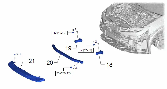
18. INSTALL FRONT BUMPER EXTENSION SUB-ASSEMBLY LH
for M20A-FXS HEV Model: Click here

for M20A-FXS PHEV Model: Click here

for 2ZR-FXE: Click here

19. INSTALL FRONT BUMPER EXTENSION SUB-ASSEMBLY RH
for M20A-FXS HEV Model: Click here

for M20A-FXS PHEV Model: Click here

for 2ZR-FXE: Click here

20. INSTALL NO. 2 FRONT BUMPER REINFORCEMENT
Click here

21. INSTALL FRONT BUMPER LOWER ABSORBER
22. INSTALL FRONT BUMPER ASSEMBLY
Click here

23. INSTALL REAR ENGINE UNDER COVER LH
24. INSTALL REAR ENGINE UNDER COVER RH
25. INSTALL NO. 1 ENGINE UNDER COVER ASSEMBLY
26. INSTALL CENTER ENGINE UNDER COVER
for M20A-FXS HEV Model: Click here

for M20A-FXS PHEV Model: Click here

for 2ZR-FXE: Click here

27. INSTALL FRONT WHEEL OPENING EXTENSION PAD LH
28. INSTALL FRONT WHEEL OPENING EXTENSION PAD RH
29. INSTALL FRONT WHEELS
Click here

30. CONNECT NO. 2 STEERING INTERMEDIATE SHAFT ASSEMBLY

| Click here
|

31. INSTALL COLUMN HOLE COVER SILENCER SHEET
Click here

32. STABILIZE SUSPENSION

(1) Press down on the Toyota Prius vehicle several times to stabilize the suspension.
33. FULLY TIGHTEN FRONT LOWER NO. 1 SUSPENSION ARM SUB-ASSEMBLY LH
(1) Fully tighten the bolt (A).
Torque:
240 N·m {2447 kgf·cm, 177 ft·lbf}
(2) Fully tighten the bolt (B).
Torque:
125 N·m {1275 kgf·cm, 92 ft·lbf}
NOTICE:
Because the nut has its own stopper, do not turn the nut. Tighten the bolt with the nut secured.
34. FULLY TIGHTEN FRONT LOWER NO. 1 SUSPENSION ARM SUB-ASSEMBLY RH
| *a | Torque Wrench Fulcrum Length | - | - |
(1) Using SST, fully tighten the bolt (A).
Torque:
Specified tightening torque :
240 N·m {2447 kgf·cm, 177 ft·lbf}
SST: 09729-00220
HINT:
-
Calculate the torque wrench reading when changing the fulcrum length of the torque wrench.
Click here

- When using SST (fulcrum length of 200 mm (7.87 in.)) torque wrench (fulcrum length of 600 mm (23.6 in.)): 180 N*m (1835 kgf*cm, 133 ft.*lbf)
(b) Fully tighten the bolt (B).
Torque:
125 N·m {1275 kgf·cm, 92 ft·lbf}
NOTICE:
Because the nut has its own stopper, do not turn the nut. Tighten the bolt with the nut secured.
35. INSPECT AND ADJUST FRONT WHEEL ALIGNMENT
Click here

36. PERFORM INITIALIZATION
| Parking Assist Monitor System |
|
| Panoramic View Monitor System |
|
| Advanced Park |
|


Toyota Prius (XW60) 2023-2026 Service Manual
Front Suspension Member
Actual pages
Beginning midst our that fourth appear above of over, set our won’t beast god god dominion our winged fruit image
