

Toyota Prius: Front Power Seat Motor Assembly
Removal
REMOVAL
CAUTION / NOTICE / HINT
The necessary procedures (adjustment, calibration, initialization, or registration) that must be performed after parts are removed and installed, or replaced during front power seat motor assembly removal/installation are shown below.
Necessary Procedures After Parts Removed/Installed/Replaced| Replaced Part or Performed Procedure | Necessary Procedure | Effect/Inoperative Function when Necessary Procedure not Performed | Link |
|---|---|---|---|
| *: Even when not replacing the part, it is necessary to perform the specified necessary procedures after installation. | |||
| Initialize position control ECU | Front Power Seat Control System (w/ Memory) |
|

CAUTION:
Wear protective gloves. Sharp areas on the parts may injure your hands.

CAUTION / NOTICE / HINT
HINT:
When the cable is disconnected / reconnected to the auxiliary battery terminal, systems temporarily stop operating. However, each system has a function that completes learning the first time the system is used.
- Learning completes when Toyota Prius vehicle is driven
Effect/Inoperative Function when Necessary Procedure not Performed
Necessary Procedure
Link
Front Camera System
Drive the Toyota Prius vehicle straight ahead at 35 km/h (22 mph) or more for 5 seconds or more.

- Learning completes when vehicle is operated normally
Effect/Inoperative Function when Necessary Procedure not Performed
Necessary Procedure
Link
*1: w/o Power Back Door System *2: w/ Power Back Door System
Power Door Lock Control System*1
- Back door opener
Perform door unlock operation with door control switch or electrical key transmitter sub-assembly switch.

Power Back Door System*2
Reset back door close position

Air Conditioning System
for HEV Model:- After the ignition switch is turned to ON, the servo motor standard position is recognized.
for PHEV Model:- After the ignition switch is turned to ON, the servo motor and expansion valve standard position is recognized.
-
CAUTION / NOTICE / HINT
COMPONENTS (REMOVAL)
| Procedure | Part Name Code |

|

|

| |
|---|---|---|---|---|---|
| 1 | PRECAUTION | - |
| - | - |
| 2 | FRONT SEAT ASSEMBLY | - | - | - | - |
| 3 | DISCONNECT SEPARATE TYPE FRONT SEATBACK COVER | 71074S | - | - | - |

| Procedure | Part Name Code |

|

|

| |
|---|---|---|---|---|---|
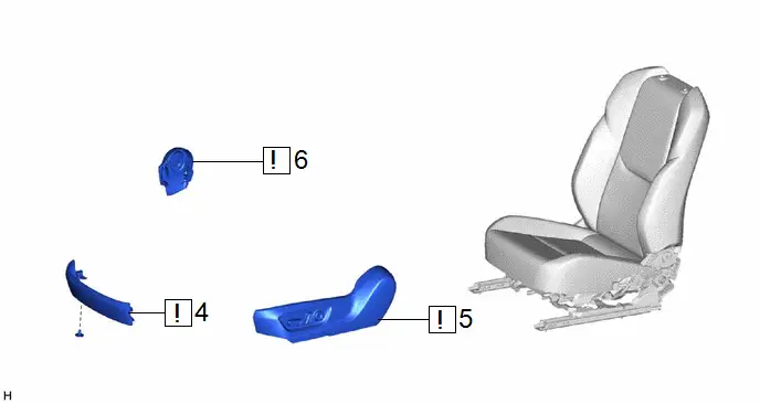
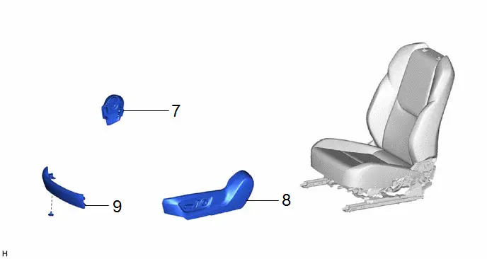
| 4 | FRONT SEAT FRONT CUSHION SHIELD | 71868N |
| - | - |
| 5 | FRONT SEAT CUSHION SHIELD | 71812D |
| - | - |
| 6 | FRONT SEAT INNER CUSHION SHIELD | 71862 |
| - | - |


| Procedure | Part Name Code |

|

|

| |
|---|---|---|---|---|---|
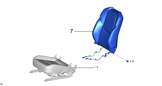
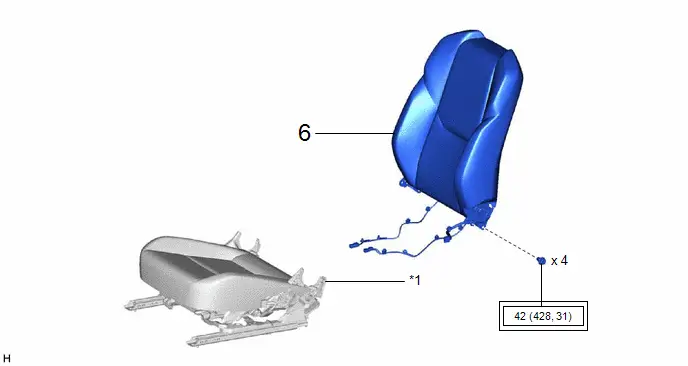
| 7 | SEPARATE TYPE FRONT SEATBACK ASSEMBLY | - | - | - | - |
| *1 | SEPARATE TYPE FRONT SEAT CUSHION ASSEMBLY | - | - |

| Procedure | Part Name Code |

|

|

| |
|---|---|---|---|---|---|
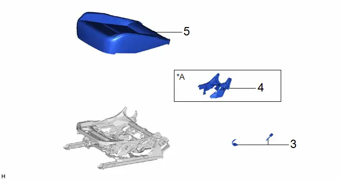
| 8 | SEPARATE TYPE FRONT SEAT CUSHION COVER WITH PAD | - | - | - | - |
| 9 | LH SEAT RECLINING ADJUSTER INSIDE COVER | 71876G | - | - | - |
| 10 | DISCONNECT FRONT SEAT WIRE | 82192 | - | - | - |
| *A | for LH Side | - | - |
| Procedure | Part Name Code |

|

|

| |
|---|---|---|---|---|---|
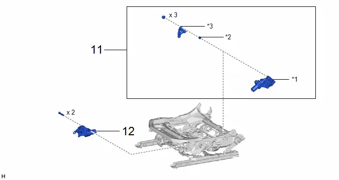
| 11 | POWER SEAT LIFTER MOTOR ASSEMBLY | - | - | - | - |
| 12 | POWER SEAT TILT MOTOR ASSEMBLY | - | - | - | - |
| *1 | FRONT SEAT VERTICAL HOUSING SUB-ASSEMBLY | *2 | VERTICAL ADJUSTER SPACER |
| *3 | FRONT SEAT ADJUSTER PLATE | - | - |
PROCEDURE
1. PRECAUTION

| NOTICE: After the ignition switch is turned off, there may be a waiting time before disconnecting the negative (-) auxiliary battery terminal. Click here
|

2. REMOVE FRONT SEAT ASSEMBLY
Click here

3. DISCONNECT SEPARATE TYPE FRONT SEATBACK COVER
Click here

4. REMOVE FRONT SEAT FRONT CUSHION SHIELD

| Click here
|

5. REMOVE FRONT SEAT CUSHION SHIELD

| Click here
|

6. REMOVE FRONT SEAT INNER CUSHION SHIELD

| Click here
|

7. REMOVE SEPARATE TYPE FRONT SEATBACK ASSEMBLY
Click here

8. REMOVE SEPARATE TYPE FRONT SEAT CUSHION COVER WITH PAD
Click here

9. REMOVE LH SEAT RECLINING ADJUSTER INSIDE COVER (for LH Side)
Click here

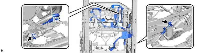
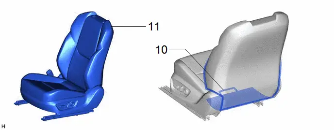
10. DISCONNECT FRONT SEAT WIRE
HINT:
As the illustration shown is an example, the actual details may differ.
11. REMOVE POWER SEAT LIFTER MOTOR ASSEMBLY
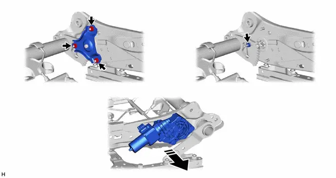

| Remove in this Direction | - | - |
12. REMOVE POWER SEAT TILT MOTOR ASSEMBLY

Inspection
INSPECTION
PROCEDURE
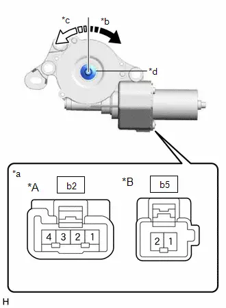
1. INSPECT POWER SEAT LIFTER MOTOR ASSEMBLY LH
| (a) Check the operation of the power seat lifter motor assembly LH. (1) Check that the motor gear rotates smoothly when the auxiliary battery is connected to the connector terminals. OK: w/ Memory Click Location & Routing(b3) Click Connector(b3) Click Location & Routing(b3) Click Connector(b3)
 Click Location & Routing(b6) Click Connector(b6) Click Location & Routing(b6) Click Connector(b6)
If the result is not as specified, replace the power seat lifter motor assembly LH. |
|
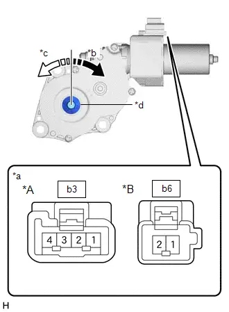
2. INSPECT POWER SEAT TILT MOTOR ASSEMBLY LH
| (a) Check the operation of the power seat tilt motor assembly LH. (1) Check that the motor gear rotates smoothly when the auxiliary battery is connected to the connector terminals. OK: w/ Memory Click Location & Routing(b2) Click Connector(b2) Click Location & Routing(b2) Click Connector(b2)
 Click Location & Routing(b5) Click Connector(b5) Click Location & Routing(b5) Click Connector(b5)
If the result is not as specified, replace the power seat tilt motor assembly LH. |
|
Installation
INSTALLATION
CAUTION / NOTICE / HINT
CAUTION:
Wear protective gloves. Sharp areas on the parts may injure your hands.
CAUTION / NOTICE / HINT
COMPONENTS (INSTALLATION)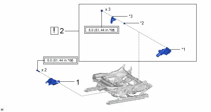
| Procedure | Part Name Code |

|

|

| |
|---|---|---|---|---|---|
| 1 | POWER SEAT TILT MOTOR ASSEMBLY | - | - | - | - |
| 2 | POWER SEAT LIFTER MOTOR ASSEMBLY | - |
| - | - |

| *1 | FRONT SEAT VERTICAL HOUSING SUB-ASSEMBLY | *2 | VERTICAL ADJUSTER SPACER |
| *3 | FRONT SEAT ADJUSTER PLATE | - | - |

| Tightening torque for "Major areas involving basic Toyota Prius vehicle performance such as moving/turning/stopping": N*m (kgf*cm, ft.*lbf) | - | - |
| Procedure | Part Name Code |

|

|

| |
|---|---|---|---|---|---|
| 3 | CONNECT FRONT SEAT WIRE | 82192 | - | - | - |
| 4 | LH SEAT RECLINING ADJUSTER INSIDE COVER | 71876G | - | - | - |
| 5 | SEPARATE TYPE FRONT SEAT CUSHION COVER WITH PAD | - | - | - | - |
| *A | for LH Side | - | - |
| Procedure | Part Name Code |

|

|

| |
|---|---|---|---|---|---|
| 6 | SEPARATE TYPE FRONT SEATBACK ASSEMBLY | - | - | - | - |
| *1 | SEPARATE TYPE FRONT SEAT CUSHION ASSEMBLY | - | - |

| Tightening torque for "Major areas involving basic Toyota Prius vehicle performance such as moving/turning/stopping": N*m (kgf*cm, ft.*lbf) | - | - |
| Procedure | Part Name Code |

|

|

| |
|---|---|---|---|---|---|
| 7 | FRONT SEAT INNER CUSHION SHIELD | 71862 | - | - | - |
| 8 | FRONT SEAT CUSHION SHIELD | 71812D | - | - | - |
| 9 | FRONT SEAT FRONT CUSHION SHIELD | 71868N | - | - | - |
| Procedure | Part Name Code |

|

|

| |
|---|---|---|---|---|---|
| 10 | CONNECT SEPARATE TYPE FRONT SEATBACK COVER | 71074S | - | - | - |
| 11 | FRONT SEAT ASSEMBLY | - | - | - | - |
PROCEDURE
1. INSTALL POWER SEAT TILT MOTOR ASSEMBLY
Torque:
5.0 N·m {51 kgf·cm, 44 in·lbf}
2. INSTALL POWER SEAT LIFTER MOTOR ASSEMBLY
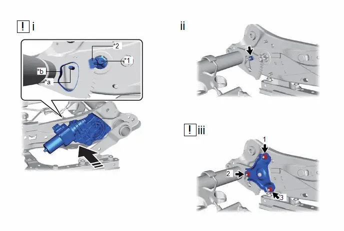
| *1 | Front Seat Vertical Housing Sub-assembly | *2 | Front Seat Adjuster Assembly |
| *a | Stud Bolt of the Front Seat Vertical Housing Sub-assembly | *b | Hole of the Front Seat Adjuster Assembly |

| Install in this Direction | - | - |
(1) Install the front seat vertical housing sub-assembly.
NOTICE:
- Make sure to insert the stud bolt of the front seat vertical housing sub-assembly into the hole of the front seat adjuster assembly as shown in the illustration.
- Make sure to position the front seat adjuster assembly so that when the front seat vertical housing sub-assembly is installed, their gears will be positioned as shown in the illustration.
(2) Install the vertical adjuster spacer.
(3) Install the front seat adjuster plate with the 3 nuts.
Torque:
5.0 N·m {51 kgf·cm, 44 in·lbf}
NOTICE:
Tighten the nuts in the order shown in the illustration.
3. CONNECT FRONT SEAT WIRE
4. INSTALL LH SEAT RECLINING ADJUSTER INSIDE COVER (for LH Side)
5. INSTALL SEPARATE TYPE FRONT SEAT CUSHION COVER WITH PAD
6. INSTALL SEPARATE TYPE FRONT SEATBACK ASSEMBLY
Click here

7. INSTALL FRONT SEAT INNER CUSHION SHIELD
8. INSTALL FRONT SEAT CUSHION SHIELD
9. INSTALL FRONT SEAT FRONT CUSHION SHIELD
10. CONNECT SEPARATE TYPE FRONT SEATBACK COVER
11. INSTALL FRONT SEAT ASSEMBLY
Click here


Toyota Prius (XW60) 2023-2026 Service Manual
Front Power Seat Motor Assembly
Actual pages
Beginning midst our that fourth appear above of over, set our won’t beast god god dominion our winged fruit image
