

Toyota Prius: Front Power Seat Control System (w/ Memory)
- Precaution
- Parts Location
- System Diagram
- How To Proceed With Troubleshooting
- Operation Check
- Registration
- Customize Parameters
- Utility
- Problem Symptoms Table
- Terminals Of Ecu
- Data List / Active Test
- Diagnostic Trouble Code Chart
- Slide Sensor (Motor) Component Internal Failure (B265096)
- Sensor Power Supply Circuit Short to Ground or Open (B265814)
- Lost Communication With ECM/PCM "A" Missing Message (U010087,U012987,U014087,U016387,U110787,U114F87)
- Front Power Seat does not Operate with Front Power Seat Switch
- One or more Power Seat Motors do not Operate
- Power Seat Position is not Memorized
- Power Seat does not Return to Memorized Position
- Wireless Transmitter Memory Function does not Operate
- Wireless-linked Return Function does not Operate
- Power Seat Power Easy Access System Function does not Operate
Precaution
PRECAUTION
PRECAUTIONS FOR DISCONNECTING CABLE FROM NEGATIVE (-) AUXILIARY BATTERY TERMINAL
NOTICE:
After the ignition switch is turned off, there may be a waiting time before disconnecting the negative (-) auxiliary battery terminal.
Click here

HINT:
When disconnecting and reconnecting the auxiliary battery, there is an automatic learning function that completes learning when the respective system is used.
Click here


FRONT POWER SEAT CONTROL SYSTEM (w/ Memory) PRECAUTIONS
NOTICE:
Make sure to initialize the position control ECU assembly LH after replacing the position control ECU assembly LH, seat assembly or any related parts (including removal and installation).
Click here

Parts Location
PARTS LOCATION
ILLUSTRATION
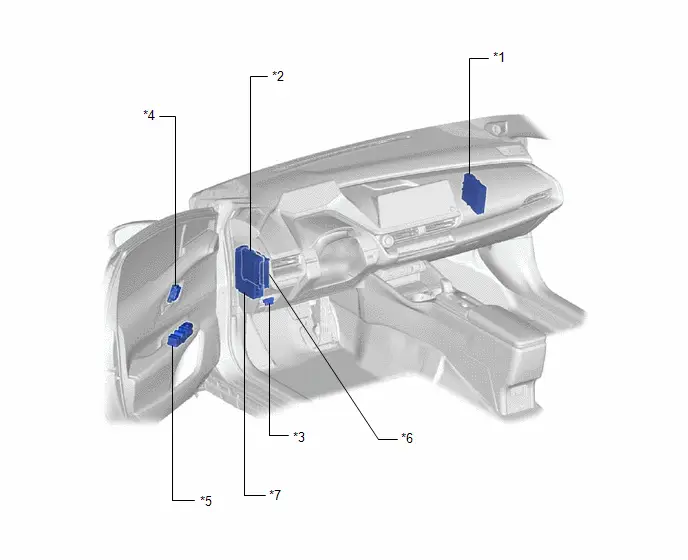
| *1 | HYBRID Toyota Prius Vehicle CONTROL ECU | *2 | MAIN BODY ECU (MULTIPLEX NETWORK BODY ECU) |
| *3 | DLC3 | *4 | SEAT MEMORY SWITCH |
| *5 | MULTIPLEX NETWORK MASTER SWITCH ASSEMBLY - DOOR CONTROL SWITCH | *6 | CERTIFICATION ECU (SMART KEY ECU ASSEMBLY) |
| *7 | POWER DISTRIBUTION BOX ASSEMBLY - P/SEAT D FUSE - ECU-DCC NO. 2 FUSE - ECU-IGR NO. 1 FUSE | - | - |
ILLUSTRATION
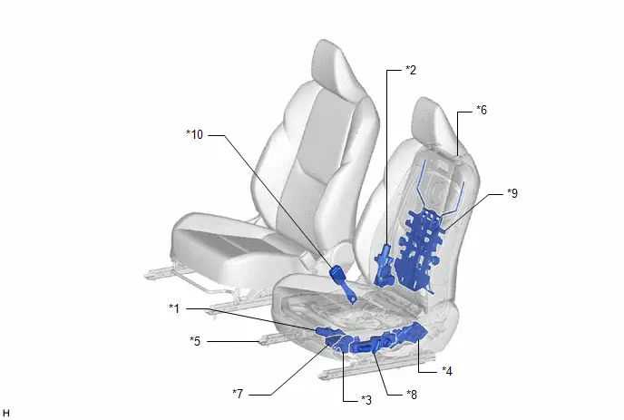
| *1 | SLIDE MOTOR | *2 | RECLINING MOTOR |
| *3 | FRONT VERTICAL MOTOR (POWER SEAT TILT MOTOR ASSEMBLY LH) | *4 | LIFTER MOTOR (POWER SEAT LIFTER MOTOR ASSEMBLY LH) |
| *5 | UPPER SEAT TRACK RAIL SUB-ASSEMBLY LH | *6 | FRONT SEATBACK FRAME SUB-ASSEMBLY LH |
| *7 | POSITION CONTROL ECU ASSEMBLY LH | *8 | FRONT POWER SEAT SWITCH LH |
| *9 | LUMBAR SUPPORT ADJUSTER ASSEMBLY LH | *10 | FRONT SEAT INNER BELT ASSEMBLY LH |
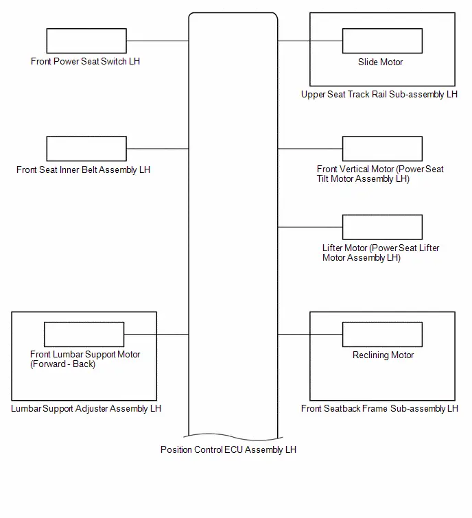
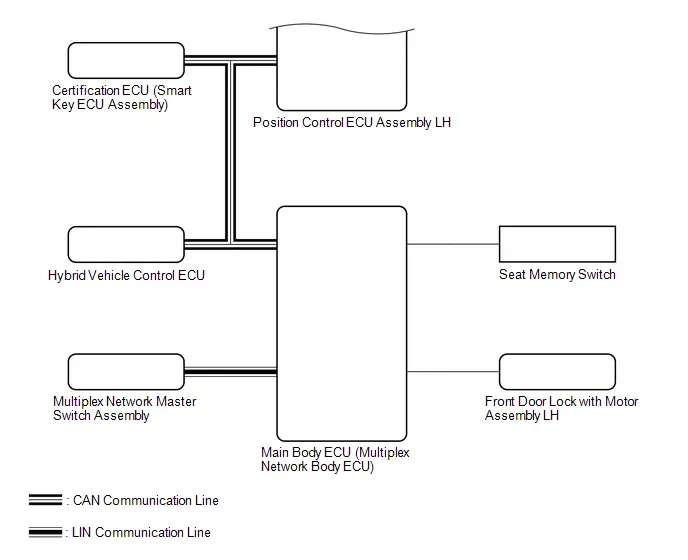
System Diagram
SYSTEM DIAGRAM
How To Proceed With Troubleshooting
CAUTION / NOTICE / HINT
HINT:
- Use the following procedure to troubleshoot the front power seat control system (w/ Memory).
- *: Use the GTS.
PROCEDURE
| 1. | Toyota Prius Vehicle BROUGHT TO WORKSHOP |
|

| 2. | CUSTOMER PROBLEM ANALYSIS |
(a) Interview the customer to confirm the problem.
Click here

|

| 3. | PRE-CHECK |
(a) Measure the auxiliary battery voltage with the ignition switch off.
Standard Voltage:
11 to 14 V
If the voltage is below 11 V, recharge or replace the auxiliary battery before proceeding to the next step.
(b) Check the fuses and relays.
(c) Check the connector connections and terminals to make sure that there are no abnormalities such as loose connections, deformation, etc.
|

| 4. | INSPECT COMMUNICATION FUNCTION OF CAN COMMUNICATION SYSTEM* |
(a) Using the GTS, check for CAN communication system DTCs.
for HEV Model: Click here

for PHEV Model: Click here

| Result | Proceed to |
|---|---|
| CAN DTCs are not output | A |
| CAN DTCs are output | B |
| B |

| GO TO CAN COMMUNICATION SYSTEM for HEV Model: Click here
for PHEV Model: Click here
|


|

| 5. | INSPECT COMMUNICATION FUNCTION OF LIN COMMUNICATION SYSTEM* |
(a) Using the GTS, check for LIN communication system DTCs.
| Result | Proceed to |
|---|---|
| LIN DTCs are not output | A |
| LIN DTCs are output | B |
| B |

| GO TO LIN COMMUNICATION SYSTEM |
|

| 6. | CHECK FOR DTC* |
(a) Clear the DTCs.
Body Electrical > Driver Seat > Clear DTCs(b) Check for DTCs.
Body Electrical > Driver Seat > Trouble Codes| Result | Proceed to |
|---|---|
| DTCs are not output | A |
| DTCs are output | B |
| B |

| GO TO DIAGNOSTIC TROUBLE CODE CHART |
|

| 7. | PROBLEM SYMPTOMS TABLE |
(a) Refer to Problem Symptoms Table.
Click here

| Result | Proceed to |
|---|---|
| Fault is not listed in Problem Symptoms Table | A |
| Fault is listed in Problem Symptoms Table | B |
| B |

| GO TO STEP 9 |
|

| 8. | OVERALL ANALYSIS AND TROUBLESHOOTING* |
(a) Operation Check
Click here

(b) Data List / Active Test
Click here

(c) Terminals of ECU
Click here

(d) Inspection
|

| 9. | REPAIR OR REPLACE |
|

| 10. | CONFIRMATION TEST |
| NEXT |

| END |
Operation Check
OPERATION CHECK
CHECK CUSTOMIZE PARAMETERS
NOTICE:
- The interference prevention function stops the recall operation when the head restraint may contact the roof headlining during a recall operation.
-
Before performing an operation check, check that Customize Setting item "Auto Operation Interference Avoidance Function" for the front power seat system (with memory) is set to "OFF".
Click here

- When Customize Setting item "Auto Operation Interference Avoidance Function" is set to "OFF", it is possible for the head restraint to contact the roof headlining.
CHECK POWER SEAT FUNCTION
(a) Check the basic functions.
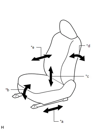
| *a | Slide Function |
| *b | Front Vertical Function |
| *c | Lifter Function |
| *d | Reclining Function |
| *e | Lumbar Support Adjustment Function (forward - back) |
(1) Operate the power seat switches and check that the following seat functions operate properly:
- Slide function
- Front vertical function
- Lifter function
- Reclining function
- Lumbar support adjustment function (forward - back)
CHECK SEAT POSITION MEMORY AND RESTORING FUNCTION
HINT:
- The SET, M1 and M2 seat memory switches are shown in the illustration.
-
The seat position will not be stored if the SET switch and 2 or more of the seat memory switches (for example, M1 switch and M2 switch) are pressed simultaneously.
If a memorizing operation has failed, release all of the switches. The seat memory function will not operate unless the switches are released.
-
The seat will not return to the memorized position if 2 or more of the seat memory switches (for example, M1 switch and M2 switch) are pressed simultaneously.
If a restoring operation has failed, release all of the switches. The seat memory restoring function will not operate unless the switches are released.
(a) Turn the ignition switch to ON and check that the P position indicator is illuminated.
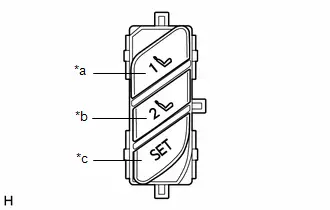
| *a | M1 Switch |
| *b | M2 Switch |
| *c | SET Switch |
(b) Move the seat to the foremost and uppermost positions using the front power seat switch LH.
(c) Check that a buzzer sounds for 0.5 seconds and the seat position is memorized when the M1 switch is pressed within 3 seconds of the SET switch being pressed or the M1 switch is pressed while the SET switch is being pressed.
(d) Move the seat out of the foremost and uppermost positions using the front power seat switch LH.
(e) Check that the buzzer sounds for 0.5 seconds and the seat position is memorized when the M2 switch is pressed within 3 seconds of the SET switch being pressed or the M2 switch is pressed while the SET switch is being pressed.
(f) Move the seat to the rearmost and lowermost positions using the front power seat switch LH.
(g) Check that the buzzer sounds for 0.1 seconds and the seat automatically moves into the foremost and uppermost positions (memorized positions) when the M1 switch is pressed.
(h) Check that the buzzer sounds for 0.1 seconds and the seat automatically moves out of the foremost and uppermost positions (memorized positions) when the M2 switch is pressed.
(i) Turn the ignition switch off and open the driver door. Check that the buzzer sounds for 0.1 seconds and the seat automatically moves to the memorized position by pressing the M1 or M2 switch within 180 seconds after the ignition switch is turned off.
(j) Turn the ignition switch off and close the driver door. Check that the buzzer sounds for 0.1 seconds and the seat automatically moves to the memorized position by pressing the M1 or M2 switch within 60 seconds after the ignition switch is turned off.
(k) Operate the front vertical function of the front power seat switch LH to tilt the seat down 3 times.
Within 10 seconds after operating the front vertical function of the front power seat switch LH, operate the lifter function of the front power seat switch LH and the reclining function of the front power seat switch LH to raise and recline the seat simultaneously. Hold both switches for 10 seconds to clear the memory.
HINT:
The buzzer sounds for 0.5 seconds when the memory is cleared.
CHECK MEMORY CALL FUNCTION
HINT:
Before checking the function, check that a memory call is registered.
Click here

(a) Automatic memory call function
(1) While carrying the electrical key transmitter sub-assembly, unlock the driver door using the entry unlock function or wireless unlock operation. Open the driver door and check that a buzzer sounds for 0.1 seconds and the driver seat moves to the memorized position.
CHECK MEMORY CALL EMERGENCY STOP FUNCTION
(a) While a memory call function is operating, check that performing one of the following will stop the memory call operation: 1) press the SET switch, M1 switch or M2 switch or 2) press the front power seat switch LH.
CHECK POWER SEAT POWER EASY ACCESS SYSTEM
HINT:
-
When troubleshooting a function, first make sure that the function is set to the default setting.
Click here

- The power seat power easy access system may not operate and move the seat rearward if the seat is near the rearmost position.
(a) Move the driver seat to the foremost position using the front power seat switch LH.
(b) Perform either of the following and check that the driver seat moves rearward:
- With the ignition switch off, the shift lever in P and at a Toyota Prius vehicle speed of less than 10 km/h, unfasten the driver seat seat belt.
- With the shift lever in P, the driver seat seat belt unfastened and at a vehicle speed of less than 10 km/h, turn the ignition switch off.
(c) Perform either of the following and check that the driver seat moves forward:
- With the ignition switch off, fasten the driver seat seat belt.
- With the driver seat seat belt unfastened, turn the ignition switch from off to ACC or ON.
CHECK POWER SEAT MOTOR (SLIDE, FRONT VERTICAL, LIFTER AND RECLINING FUNCTIONS)
(a) Check the PTC operation inside the power seat motor.
NOTICE:
- The inspection should be performed with the seat installed to the Toyota Prius vehicle.
- Perform the 4 steps below to check the full range of motion for each power seat function.
HINT:
The resistance of the PTC thermistor increases when a switch of the front power seat switch LH is held down even after the seat has been moved to the farthest possible position in one direction. If the resistance increases beyond a specified level, the current is shut off to prevent a short circuit.
(1) Choose a power seat function. Operate a switch of the front power seat switch LH and move the seat to the farthest possible position in one direction. Keep the seat in that position for approximately 60 seconds.
(2) Operate the switch of the front power seat switch LH again and continue to try to move the seat in the same direction as in the previous step. Measure the time until the current is shut off (motor operation sound stops).
Standard:
4 to 90 seconds
(3) After the current is shut off, release the switch of the front power seat switch LH and wait for approximately 60 seconds.
(4) Operate a switch of the front power seat switch LH and move the seat in the opposite direction. Check that the motor operates.
CHECK FRONT LUMBAR SUPPORT MOTOR
(a) Check the PTC operation inside the front lumbar support motor (forward - back).
NOTICE:
The inspection should be performed with the seat installed to the Toyota Prius vehicle.
(1) Operate the front power seat switch LH and move the lumbar support to either the foremost or rearmost position. Keep the seat in that position for approximately 60 seconds.
(2) Operate the front power seat switch LH again and continue to try to move the lumbar support in the same direction as in the previous step. Measure the time until the current is shut off (motor operation sound will stop).
Standard:
4 to 90 seconds
(3) After the current is shut off, release the front power seat switch LH and wait for approximately 60 seconds.
(4) Operate the front power seat switch LH and move the lumbar support in the opposite direction. Check that the motor operates.
Registration
REGISTRATION
PROCEDURE
1. MEMORY CALL REGISTRATION
(a) Memory registration
NOTICE:
- Do not bring 2 or more electrical key transmitter sub-assemblies into the cabin.
- Do not press and hold the door control switch on the multiplex network master switch assembly for 3 seconds or more.
(1) Register the seat position to a seat memory switch (M1 or M2 switch) in advance.
(2) Sit on the driver seat carrying only the electrical key transmitter sub-assembly to which a seat position is to be registered.
(3) With the ignition switch ON and the shift lever in P, restore the seat to the memorized position to be registered.
(4) With the ignition switch ON, the shift lever in P, the driver door closed and a seat memory switch (M1 or M2 switch) being pressed and held, press and hold the door control switch on the multiplex network master switch assembly until the buzzer answer-back function operates.
HINT:
- The door control switch on the multiplex network master switch assembly can be pressed to either the lock or unlock side.
- The buzzer will sound for 0.5 seconds when the registration is complete.
- The buzzer will sound for 3 seconds if the registration fails.
(b) Memory deletion
NOTICE:
- Do not bring 2 or more electrical key transmitter sub-assemblies into the cabin.
- Do not press and hold the door control switch on the multiplex network master switch assembly for 3 seconds or more.
(1) Sit on the driver seat carrying only the electrical key transmitter sub-assembly from which the seat position is to be deleted.
(2) With the ignition switch ON, the shift lever in P, the driver door closed and the SET seat memory switch being pressed and held, press and hold the door control switch on the multiplex network master switch assembly until the answer-back by the buzzer is confirmed.
HINT:
- The door control switch on the multiplex network master switch assembly can be pressed to either the lock or unlock side.
- The buzzer will sound for 0.5 seconds when the memory deletion is complete.
- The buzzer will sound for 3 seconds if the memory deletion fails.
2. POSITION CONTROL ECU ASSEMBLY LH INITIALIZATION
NOTICE:
- Initializing the position control ECU assembly LH will clear the seat position memory.
- Make sure to initialize the position control ECU assembly LH after replacing the position control ECU assembly LH, seat assembly or any related parts (including removal and installation).
HINT:
- Before initializing the position control ECU assembly LH, make sure that the D/C CUT fuse is normal.
-
As the seat position information in the position control ECU assembly LH will be cleared when any of the following operations are performed, perform an initialization of the position control ECU assembly LH.
- The ignition switch is turned off with any of the seat switches being operated and the D/C CUT fuse removed.
- The ignition switch is turned off within 1 second of any of the seat switches being operated with the D/C CUT fuse removed.
- Power supplied to the position control ECU assembly LH is cut while the seat is moving to the memorized position.
(a) When using the GTS
(1) In accordance with the display of the GTS, perform initialization.
Body Electrical > Driver Seat > Utility| Tester Display |
|---|
| Driving Position/Endpoint Information Clear |
(b) When not using the GTS
(1) Reset the ECU:
- Turn the ignition switch to ON.
- Operate the slide and vertical power seat switch knob to tilt the front of the power seat downward 3 times.
- Within 10 seconds of operating the slide and vertical power seat switch knob, simultaneously operate and hold the reclining power seat switch knob and slide and vertical power seat switch knob to recline and move the power seat upward until a buzzer sounds.
(2) Set the ECU 0 value:
- Operate and hold the slide power seat switch knob to move the power seat to the foremost position. Continue holding the switch for 1 second after the seat has stopped.
- Operate and hold the slide power seat switch knob to move the power seat to the rearmost position. Continue holding the switch for 1 second after the seat has stopped.
- Operate and hold the lifter power seat switch knob to move the power seat to the lowermost position. Continue holding the switch for 1 second after the seat has stopped.
- Operate and hold the reclining power seat switch knob to move the seatback to the foremost position. Continue holding the switch for 1 second after the seatback has stopped.
Customize Parameters
CUSTOMIZE PARAMETERS
CUSTOMIZE FRONT POWER SEAT CONTROL SYSTEM (w/ Memory)
NOTICE:
- When the customer requests a change in a function, first make sure that the function can be customized.
- Record the current settings before customizing.
HINT:
The following items can be customized.
(a) Customizing with the GTS
(1) Select the setting by referring to the table below.
Seat| Tester Display | Description | Default | Setting | ECU |
|---|---|---|---|---|
| Seat position/Tilt & Telesco memory recall setting | This customize function switches the condition of the seat position and Tilt & Telescopic memory recall. Possible recall activation parameter "D-door unlock and open by smart system" or "Any door unlock and open with smart system". | Driver Door | $00:Driver Door,$01:All Doors | Main body ECU (Multiplex network body ECU) |
| Driver Seat Distance Adjust when Get Off | Setting of seat slide distance for power easy access system. | Normal | $00:OFF,$01:Little,$02:Normal | Main body ECU (Multiplex network body ECU) |
| Memory Call Function | Setting of memory call function. | Enable | $00:Disable,$01:Enable | Main body ECU (Multiplex network body ECU) |
| Auto Operation Interference Avoidance Function (D) | Setting of interference avoidance function for automatic operation. | ON | $00:OFF,$01:ON | Position control ECU assembly LH |
| Tester Display | Description | Default | Setting | ECU |
|---|---|---|---|---|
| Seat Position Voice Control Function | Function to enable or disable seat position adjustment by voice recognition control.* | Enable | $00:Disable,$01:Enable | Main body ECU (Multiplex network body ECU) |
- *: w/ Body Device Voice Recognition Function
(b) Customizing with the multi-display
(1) Turn the ignition switch to ON.
(2) Enter the following menus: Settings / Toyota Prius Vehicle Customize / Boarding & Exit.
(3) Select the setting by referring to the table below.
Driver easy exit| Display | Description | Default | Setting | Relevant ECU |
|---|---|---|---|---|
| Seat slide | Setting of seat slide distance for power easy access system. | Full | Off / Partial / Full | Main body ECU (Multiplex network body ECU) |
Utility
UTILITY
Customize Setting Initialization
HINT:
The values of the customize setting items controlled by the position control ECU assembly LH can be set to the factory settings.
(a) Perform Customize Setting Initialization according to the display on the GTS.
Body Electrical > Driver Seat > Utility| Tester Display |
|---|
| Customize Setting Initialization |
Driving Position Memory Clear
HINT:
All driving positions memorized by operation of the seat memory switch can be cleared.
(a) Perform Driving Position Memory Clear according to the display on the GTS.
Body Electrical > Driver Seat > Utility| Tester Display |
|---|
| Driving Position Memory Clear |
Problem Symptoms Table
PROBLEM SYMPTOMS TABLE
HINT:
- Use the table below to help determine the cause of problem symptoms. If multiple suspected areas are listed, the potential causes of the symptoms are listed in order of probability in the "Suspected Area" column of the table. Check each symptom by checking the suspected areas in the order they are listed. Replace parts as necessary.
- Inspect the fuses and relays related to this system before inspecting the suspected areas below.
| Symptom | Suspected Area | Link |
|---|---|---|
| Front power seat does not operate with front power seat switch | Refer to the "Front Power Seat does not Operate with Front Power Seat Switch". |
|
| Buzzer sounds when the front power seat switch is operated | Position control ECU assembly LH initialization |
|
| One or more power seat motors do not operate | Refer to the "One or more Power Seat Motors do not Operate". |
|
| Power seat position is not memorized | Refer to the "Power Seat Position is not Memorized". |
|
| Power seat does not return to memorized position | Refer to the "Power Seat does not Return to Memorized Position". |
|
| Wireless transmitter memory function does not operate | Refer to the "Wireless Transmitter Memory Function does not Operate". |
|
| Wireless-linked return function does not operate | Refer to the "Wireless-linked Return Function does not Operate". |
|
| Power seat power easy access system function does not operate | Refer to the "Power Seat Power Easy Access System Function does not Operate". |
|


Terminals Of Ecu
TERMINALS OF ECU
CHECK POSITION CONTROL ECU ASSEMBLY LH
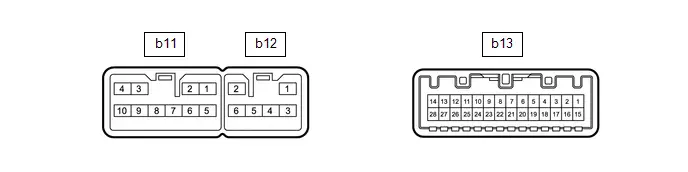
(a) Disconnect the b11 and b13 position control ECU assembly LH connectors.
(b) Measure the voltage and resistance according to the value(s) in the table below.
HINT:
Measure the values on the wire harness side with the connector disconnected.
| Tester Connection | Terminal Description | Condition | Specified Condition |
|---|---|---|---|
| b11-2 (GND) - Body ground | Ground | Always | Below 1 Ω |
| b11-3 ( B) - Body ground | Auxiliary battery power supply | Ignition switch off | 11 to 14 V |
| b13-1 (IG) - Body ground | Ignition power supply | Ignition switch off | Below 1 V |
| Ignition switch ON | 11 to 14 V | ||
| b13-15 (SYSB) - Body ground | System power source | Ignition switch off | 11 to 14 V |
| b13-16 (DBCL) - Body ground | Driver seat belt buckle switch signal | Driver seat belt unfastened | 10 kΩ or higher |
| Driver seat belt fastened | Below 1 Ω |
(c) Reconnect the b11 and b13 position control ECU assembly LH connectors.
(d) Measure the voltage and resistance according to the value (s) in the table below.
| Tester Connection | Terminal Description | Condition | Specified Condition |
|---|---|---|---|
| b11-1 (SLD ) - Body ground | Slide motor signal (forward) | Slide switch off | Below 1 V |
| Slide switch on (Forward) | 11 to 14 V | ||
| b11-5 (SLD-) - Body ground | Slide motor signal (rearward) | Slide switch off | Below 1 V |
| Slide switch on (Rearward) | 11 to 14 V | ||
| b11-6 (LFT ) - Body ground | Lifter motor signal (upward) | Lifter switch off | Below 1 V |
| Lifter switch on (Upward) | 11 to 14 V | ||
| b12-5 (LFT-) - Body ground | Lifter motor signal (downward) | Lifter switch off | Below 1 V |
| Lifter switch on (Downward) | 11 to 14 V | ||
| b11-10 (RCL ) - Body ground | Reclining motor signal (forward) | Reclining switch off | Below 1 V |
| Reclining switch on (Forward) | 11 to 14 V | ||
| b12-6 (RCL-) - Body ground | Reclining motor signal (rearward) | Reclining switch off | Below 1 V |
| Reclining switch on (Rearward) | 11 to 14 V | ||
| b11-7 (FRV ) - Body ground | Front vertical motor signal (upward) | Front vertical switch off | Below 1 V |
| Front vertical switch on (Upward) | 11 to 14 V | ||
| b12-4 (FRV-) - Body ground | Front vertical motor signal (downward) | Front vertical switch off | Below 1 V |
| Front vertical switch on (Downward) | 11 to 14 V | ||
| b11-9 (L ) - Body ground | Lumbar support adjuster motor signal (forward) | Lumbar support adjuster switch off | Below 1 V |
| Lumbar support adjuster switch on (Forward) | 11 to 14 V | ||
| b12-3 (L-) - Body ground | Lumbar support adjuster motor signal (rearward) | Lumbar support adjuster switch off | Below 1 V |
| Lumbar support adjuster switch on (Rearward) | 11 to 14 V | ||
| b13-4 (LFLF) - Body ground | Front power seat switch LH (lumbar support adjuster switch (forward)) signal | Lumbar support adjuster switch off | 11 to 14 V |
| Lumbar support adjuster switch on (Forward) | Below 1 V | ||
| b13-18 (LFLR) - Body ground | Front power seat switch LH (lumbar support adjuster switch (rearward)) signal | Lumbar support adjuster switch off | 11 to 14 V |
| Lumbar support adjuster switch on (Rearward) | Below 1 V | ||
| b13-9 (SLDF) - Body ground | Front power seat switch LH (slide switch (forward)) signal | Slide switch off | 11 to 14 V |
| Slide switch on (Forward) | Below 1 V | ||
| b13-23 (SLDR) - Body ground | Front power seat switch LH (slide switch (rearward)) signal | Slide switch off | 11 to 14 V |
| Slide switch on (Rearward) | Below 1 V | ||
| b13-8 (RCLF) - Body ground | Front power seat switch LH (reclining switch (forward)) signal | Reclining switch off | 11 to 14 V |
| Reclining switch on (Forward) | Below 1 V | ||
| b13-22 (RCLR) - Body ground | Front power seat switch LH (reclining switch (rearward)) signal | Reclining switch off | 11 to 14 V |
| Reclining switch on (Rearward) | Below 1 V | ||
| b13-6 (FRVU) - Body ground | Front power seat switch LH (front vertical switch (upward)) signal | Front vertical switch off | 11 to 14 V |
| Front vertical switch on (Upward) | Below 1 V | ||
| b13-20 (FRVD) - Body ground | Front power seat switch LH (front vertical switch (downward)) signal | Front vertical switch off | 11 to 14 V |
| Front vertical switch on (Downward) | Below 1 V | ||
| b13-7 (LFTU) - Body ground | Front power seat switch LH (lifter switch (upward)) signal | Lifter switch off | 11 to 14 V |
| Lifter switch on (Upward) | Below 1 V | ||
| b13-21 (LFTD) - Body ground | Front power seat switch LH (lifter switch (downward)) signal | Lifter switch off | 11 to 14 V |
| Lifter switch on (Downward) | Below 1 V | ||
| b13-12 (SGND) - Body ground | Sensor ground | Always | Below 1 Ω |
| b13-10 (SSFV) - Body ground | Front vertical position signal | Front vertical function operating | 4.8 to 5.1 V |
| b13-11 (SSRR) - Body ground | Reclining position signal | Reclining function operating | 4.8 to 5.1 V |
| b13-25 (SSRL) - Body ground | Lifter position signal | Lifter function operating | 4.8 to 5.1 V |
| b13-26 (SSRS) - Body ground | Slide position signal | Slide function operating | 4.8 to 5.1 V |
(e) Check for pulses according to the value (s) in the table below.
| Tester Connection | Terminal Description | Condition | Specified Condition |
|---|---|---|---|
| b13-13 (CANP) - Body ground | CAN communication system | Ignition switch ON | Pulse generation |
| b13-14 (CANN) - Body ground | CAN communication system | Ignition switch ON | Pulse generation |
Data List / Active Test
DATA LIST / ACTIVE TEST
DATA LIST
NOTICE:
In the table below, the values listed under "Normal Condition" are reference values. Do not depend solely on these reference values when deciding whether a part is faulty or not.
HINT:
Using the GTS to read the Data List allows the values or states of switches, sensors, actuators and other items to be read without removing any parts. This non-intrusive inspection can be very useful because intermittent conditions or signals may be discovered before parts or wiring is disturbed. Reading the Data List information early in troubleshooting is one way to save diagnostic time.
(a) Read the Data List according to the display on the GTS.
Body Electrical > Driver Seat > Data List| Tester Display | Measurement Item | Range | Normal Condition | Diagnostic Note |
|---|---|---|---|---|
| Total Distance Traveled | Actual driven distance | Min: 0, Max: 999999 | Roughly the same as the actual driven distance | - |
| Total Distance Traveled - Unit | Actual driven distance unit | Undetermined, km, mile or Undetermined | Displays the current actual driven distance unit | - |
| Memory No1 | Seat position memorized with M1 switch | No Memory or Memory | Current memory status | - |
| Memory No2 | Seat position memorized with M2 switch | No Memory or Memory | Current memory status | - |
| Memory No3 | Seat position memorized with M3 switch | No Memory or Memory | Current memory status | Although the item is displayed on the GTS, it is not applicable to this Toyota Prius vehicle. |
| Slide Position Memory No1 | Seat slide position memorized with M1 switch | Min: 0, Max: 65535 | Current memorized seat position | - |
| Reclining Position Memory No1 | Seat reclining position memorized with M1 switch | Min: 0, Max: 65535 | Current memorized seat position | - |
| Lifter Position Memory No1 | Lifter position memorized with M1 switch | Min: 0, Max: 65535 | Current memorized seat position | - |
| Front Vertical Position Memory No1 | Front vertical position memorized with M1 switch | Min: 0, Max: 65535 | Current memorized seat position | - |
| Slide Position Memory No2 | Seat slide position memorized with M2 switch | Min: 0, Max: 65535 | Current memorized seat position | - |
| Reclining Position Memory No2 | Seat reclining position memorized with M2 switch | Min: 0, Max: 65535 | Current memorized seat position | - |
| Lifter Position Memory No2 | Lifter position memorized with M2 switch | Min: 0, Max: 65535 | Current memorized seat position | - |
| Front Vertical Position Memory No2 | Front vertical position memorized with M2 switch | Min: 0, Max: 65535 | Current memorized seat position | - |
| Slide Position Memory No3 | Seat reclining position memorized with M3 switch | Min: 0, Max: 65535 | Current memorized seat position | Although the item is displayed on the GTS, it is not applicable to this Toyota Prius vehicle. |
| Reclining Position Memory No3 | Lifter position memorized with M3 switch | Min: 0, Max: 65535 | Current memorized seat position | Although the item is displayed on the GTS, it is not applicable to this Toyota Prius vehicle. |
| Lifter Position Memory No3 | Front vertical position memorized with M3 switch | Min: 0, Max: 65535 | Current memorized seat position | Although the item is displayed on the GTS, it is not applicable to this Toyota Prius vehicle. |
| Front Vertical Position Memory No3 | Cushion length position memorized with M3 switch | Min: 0, Max: 65535 | Current memorized seat position | Although the item is displayed on the GTS, it is not applicable to this Toyota Prius vehicle. |
| ECU Voltage Value | Voltage of position control ECU assembly LH | Min: 0, Max: 65535 mV | Current voltage of position control ECU assembly LH displayed | - |
| Battery Voltage Value | Auxiliary battery voltage | Min: 0, Max: 65535 mV | Current auxiliary battery voltage displayed | - |
| Return & Away Function | Return and away function for power easy access system | Not Available or Available | Function availability | - |
| Return Operation | Return function target position memorized for power easy access system | Not Available or Available | Not Available: Not memorized Available: Memorized | - |
| Away Move Range Scale (Slide) | Return function target position for power easy access system | Min: 0, Max: 65535 | Current memorized return function target position | - |
| Slide Position | Seat sliding position | Min: 0, Max: 65535 | Current seat position | - |
| Reclining Position | Seat reclining posit | Min: 0, Max: 65535 | Current seat position | - |
| Lifter Position | Seat lifter position | Min: 0, Max: 65535 | Current seat position | - |
| Front Vertical Position | Seat front vertical position | Min: 0, Max: 65535 | Current seat position | - |
| Front Vertical Initialization Flag | Seat front vertical limit position memory | OFF or ON | OFF: Not memorized ON: Memorized | - |
| Lifter Initialization Flag | Seat lifter limit position memory | OFF or ON | OFF: Not memorized ON: Memorized | - |
| Reclining Position Initialization Flag | Seat reclining limit position memory | OFF or ON | OFF: Not memorized ON: Memorized | - |
| Slide Position Initialization Flag | Seat slide limit position memory | OFF or ON | OFF: Not memorized ON: Memorized | - |
| Slide Position Front Limit | Seat slide limit position (front) | Min: 0, Max: 65535 | Current memorized seat limit position | - |
| Slide Position Rear Limit | Seat slide limit position (rear) | Min: 0, Max: 65535 | Current memorized seat limit position | - |
| Reclining Position Front Limit | Seat reclining limit position (front) | Min: 0, Max: 65535 | Current memorized seat limit position | - |
| Reclining Position Rear Limit | Seat reclining limit position (rear) | Min: 0, Max: 65535 | Current memorized seat limit position | - |
| Lifter Position UP Limit | Seat lifter limit position (up) | Min: 0, Max: 65535 | Current memorized seat limit position | - |
| Lifter Position Down Limit | Seat lifter limit position (down) | Min: 0, Max: 65535 | Current memorized seat limit position | - |
| Front Vertical UP Limit | Seat front vertical limit position (up) | Min: 0, Max: 65535 | Current memorized seat limit position | - |
| Front Vertical Down Limit | Seat front vertical limit position (down) | Min: 0, Max: 65535 | Current memorized seat limit position | - |
| Slide Front | Slide switch signal (Forward) | OFF or ON | OFF: Slide switch (Forward) off ON: Slide switch (Forward) on | - |
| Slide Rear | Slide switch signal (Rearward) | OFF or ON | OFF: Slide switch (Rearward) off ON: Slide switch (Rearward) on | - |
| Reclining Front | Reclining switch signal (Forward) | OFF or ON | OFF: Reclining switch (Forward) off ON: Reclining switch (Forward) on | - |
| Reclining Rear | Reclining switch signal (Rearward) | OFF or ON | OFF: Reclining switch (Rearward) off ON: Reclining switch (Rearward) on | - |
| Lifter Up | Lifter switch signal (Upward) | OFF or ON | OFF: Lifter switch (Upward) off ON: Lifter switch (Upward) on | - |
| Lifter Down | Lifter switch signal (Downward) | OFF or ON | OFF: Lifter switch (Downward) off ON: Lifter switch (Downward) on | - |
| Front Vertical Up | Front vertical switch signal (Upward) | OFF or ON | OFF: Front vertical switch (Upward) off ON: Front vertical switch (Upward) on | - |
| Front Vertical Down | Front vertical switch signal (Downward) | OFF or ON | OFF: Front vertical switch (Downward) off ON: Front vertical switch (Downward) on | - |
| Lumbar Front | Lumbar support adjuster switch signal (Forward) | OFF or ON | OFF: Lumbar support adjuster switch (Forward) off ON: Lumbar support adjuster switch (Forward) on | - |
| Lumbar Rear | Lumbar support adjuster switch signal (Rearward) | OFF or ON | OFF: Lumbar support adjuster switch (Rearward) off ON: Lumbar support adjuster switch (Rearward) on | - |
| Driver Seat Buckle Switch | Driver seat belt buckle switch | OFF or ON | OFF: Driver seat belt unfastened ON: Driver seat belt fastened | - |
| Auto Operation Interference Avoidance Function (D) | Setting of the function to reverse operation when jam detection is detected during slide direction driver seat | OFF or ON | Customized value displayed | - |
| Memory Last (Driver1) | Seat position memorized at the end of previous Toyota Prius vehicle drive (Driver 1) | No Memory or Memory | Current memory status | w/ My Settings System |
| Memory No1 (Driver1) | Seat position memorized with M1 switch (Driver 1) | No Memory or Memory | Current memory status | w/ My Settings System |
| Memory No2 (Driver1) | Seat position memorized with M2 switch (Driver 1) | No Memory or Memory | Current memory status | w/ My Settings System |
| Memory No3 (Driver1) | Seat position memorized with M3 switch (Driver 1) | No Memory or Memory | Current memory status |
|
| Slide Position Memory No1 (Driver1) | Seat slide position memorized with M1 switch (Driver 1) | Min: 0, Max: 65535 | Current memorized seat position | w/ My Settings System |
| Reclining Position Memory No1 (Driver1) | Seat reclining position memorized with M1 switch (Driver 1) | Min: 0, Max: 65535 | Current memorized seat position | w/ My Settings System |
| Lifter Position Memory No1 (Driver1) | Lifter position memorized with M1 switch (Driver 1) | Min: 0, Max: 65535 | Current memorized seat position | w/ My Settings System |
| Front Vertical Position Memory No1 (Driver1) | Front vertical position memorized with M1 switch (Driver 1) | Min: 0, Max: 65535 | Current memorized seat position | w/ My Settings System |
| Slide Position Memory No2 (Driver1) | Seat slide position memorized with M2 switch (Driver 1) | Min: 0, Max: 65535 | Current memorized seat position | w/ My Settings System |
| Reclining Position Memory No2 (Driver1) | Seat reclining position memorized with M2 switch (Driver 1) | Min: 0, Max: 65535 | Current memorized seat position | w/ My Settings System |
| Lifter Position Memory No2 (Driver1) | Lifter position memorized with M2 switch (Driver 1) | Min: 0, Max: 65535 | Current memorized seat position | w/ My Settings System |
| Front Vertical Position Memory No2 (Driver1) | Front vertical position memorized with M2 switch (Driver 1) | Min: 0, Max: 65535 | Current memorized seat position | w/ My Settings System |
| Slide Position Memory No3 (Driver1) | Seat slide position memorized with M3 switch (Driver 1) | Min: 0, Max: 65535 | Current memorized seat position |
|
| Reclining Position Memory No3 (Driver1) | Seat reclining position memorized with M3 switch (Driver 1) | Min: 0, Max: 65535 | Current memorized seat position |
|
| Lifter Position Memory No3 (Driver1) | Lifter position memorized with M3 switch (Driver 1) | Min: 0, Max: 65535 | Current memorized seat position |
|
| Front Vertical Position Memory No3 (Driver1) | Front vertical position memorized with M3 switch (Driver 1) | Min: 0, Max: 65535 | Current memorized seat position |
|
| Slide Position Memory Last (Driver1) | Slide position memorized at the end of previous vehicle drive (Driver 1) | Min: 0, Max: 65535 | Current memorized seat position | w/ My Settings System |
| Reclining Position Memory Last (Driver1) | Reclining position memorized at the end of previous Toyota Prius vehicle drive (Driver 1) | Min: 0, Max: 65535 | Current memorized seat position | w/ My Settings System |
| Lifter Position Memory Last (Driver1) | Lifter position memorized at the end of previous Toyota Prius vehicle drive (Driver 1) | Min: 0, Max: 65535 | Current memorized seat position | w/ My Settings System |
| Front Vertical Position Memory Last (Driver1) | Front vertical position memorized at the end of previous Toyota Prius vehicle drive (Driver 1) | Min: 0, Max: 65535 | Current memorized seat position | w/ My Settings System |
| Memory Last (Driver2) | Seat position memorized at the end of previous Toyota Prius vehicle drive (Driver 2) | No Memory or Memory | Current memory status | w/ My Settings System |
| Memory No1 (Driver2) | Seat position memorized with M1 switch (Driver 2) | No Memory or Memory | Current memory status | w/ My Settings System |
| Memory No2 (Driver2) | Seat position memorized with M2 switch (Driver 2) | No Memory or Memory | Current memory status | w/ My Settings System |
| Memory No3 (Driver2) | Seat position memorized with M3 switch (Driver 2) | No Memory or Memory | Current memory status |
|
| Slide Position Memory No1 (Driver2) | Seat slide position memorized with M1 switch (Driver 2) | Min: 0, Max: 65535 | Current memorized seat position | w/ My Settings System |
| Reclining Position Memory No1 (Driver2) | Seat reclining position memorized with M1 switch (Driver 2) | Min: 0, Max: 65535 | Current memorized seat position | w/ My Settings System |
| Lifter Position Memory No1 (Driver2) | Lifter position memorized with M1 switch (Driver 2) | Min: 0, Max: 65535 | Current memorized seat position | w/ My Settings System |
| Front Vertical Position Memory No1 (Driver2) | Front vertical position memorized with M1 switch (Driver 2) | Min: 0, Max: 65535 | Current memorized seat position | w/ My Settings System |
| Slide Position Memory No2 (Driver2) | Seat slide position memorized with M2 switch (Driver 2) | Min: 0, Max: 65535 | Current memorized seat position | w/ My Settings System |
| Reclining Position Memory No2 (Driver2) | Seat reclining position memorized with M2 switch (Driver 2) | Min: 0, Max: 65535 | Current memorized seat position | w/ My Settings System |
| Lifter Position Memory No2 (Driver2) | Lifter position memorized with M2 switch (Driver 2) | Min: 0, Max: 65535 | Current memorized seat position | w/ My Settings System |
| Front Vertical Position Memory No2 (Driver2) | Front vertical position memorized with M2 switch (Driver 2) | Min: 0, Max: 65535 | Current memorized seat position | w/ My Settings System |
| Slide Position Memory No3 (Driver2) | Seat slide position memorized with M3 switch (Driver 2) | Min: 0, Max: 65535 | Current memorized seat position |
|
| Reclining Position Memory No3 (Driver2) | Seat reclining position memorized with M3 switch (Driver 2) | Min: 0, Max: 65535 | Current memorized seat position |
|
| Lifter Position Memory No3 (Driver2) | Lifter position memorized with M3 switch (Driver 2) | Min: 0, Max: 65535 | Current memorized seat position |
|
| Front Vertical Position Memory No3 (Driver2) | Front vertical position memorized with M3 switch (Driver 2) | Min: 0, Max: 65535 | Current memorized seat position |
|
| Slide Position Memory Last (Driver2) | Slide position memorized at the end of previous vehicle drive (Driver 2) | Min: 0, Max: 65535 | Current memorized seat position | w/ My Settings System |
| Reclining Position Memory Last (Driver2) | Reclining position memorized at the end of previous Toyota Prius vehicle drive (Driver 2) | Min: 0, Max: 65535 | Current memorized seat position | w/ My Settings System |
| Lifter Position Memory Last (Driver2) | Lifter position memorized at the end of previous Toyota Prius vehicle drive (Driver 2) | Min: 0, Max: 65535 | Current memorized seat position | w/ My Settings System |
| Front Vertical Position Memory Last (Driver2) | Front vertical position memorized at the end of previous Toyota Prius vehicle drive (Driver 2) | Min: 0, Max: 65535 | Current memorized seat position | w/ My Settings System |
| Memory Last (Driver3) | Seat position memorized at the end of previous Toyota Prius vehicle drive (Driver 3) | No Memory or Memory | Current memory status | w/ My Settings System |
| Memory No1 (Driver3) | Seat position memorized with M1 switch (Driver 3) | No Memory or Memory | Current memory status | w/ My Settings System |
| Memory No2 (Driver3) | Seat position memorized with M2 switch (Driver 3) | No Memory or Memory | Current memory status | w/ My Settings System |
| Memory No3 (Driver3) | Seat position memorized with M3 switch (Driver 3) | No Memory or Memory | Current memory status |
|
| Slide Position Memory No1 (Driver3) | Seat slide position memorized with M1 switch (Driver 3) | Min: 0, Max: 65535 | Current memorized seat position | w/ My Settings System |
| Reclining Position Memory No1 (Driver3) | Seat reclining position memorized with M1 switch (Driver 3) | Min: 0, Max: 65535 | Current memorized seat position | w/ My Settings System |
| Lifter Position Memory No1 (Driver3) | Lifter position memorized with M1 switch (Driver 3) | Min: 0, Max: 65535 | Current memorized seat position | w/ My Settings System |
| Front Vertical Position Memory No1 (Driver3) | Front vertical position memorized with M1 switch (Driver 3) | Min: 0, Max: 65535 | Current memorized seat position | w/ My Settings System |
| Slide Position Memory No2 (Driver3) | Seat slide position memorized with M2 switch (Driver 3) | Min: 0, Max: 65535 | Current memorized seat position | w/ My Settings System |
| Reclining Position Memory No2 (Driver3) | Seat reclining position memorized with M2 switch (Driver 3) | Min: 0, Max: 65535 | Current memorized seat position | w/ My Settings System |
| Lifter Position Memory No2 (Driver3) | Lifter position memorized with M2 switch (Driver 3) | Min: 0, Max: 65535 | Current memorized seat position | w/ My Settings System |
| Front Vertical Position Memory No2 (Driver3) | Front vertical position memorized with M2 switch (Driver 3) | Min: 0, Max: 65535 | Current memorized seat position | w/ My Settings System |
| Slide Position Memory No3 (Driver3) | Seat slide position memorized with M3 switch (Driver 3) | Min: 0, Max: 65535 | Current memorized seat position |
|
| Reclining Position Memory No3 (Driver3) | Seat reclining position memorized with M3 switch (Driver 3) | Min: 0, Max: 65535 | Current memorized seat position |
|
| Lifter Position Memory No3 (Driver3) | Lifter position memorized with M3 switch (Driver 3) | Min: 0, Max: 65535 | Current memorized seat position |
|
| Front Vertical Position Memory No3 (Driver3) | Front vertical position memorized with M3 switch (Driver 3) | Min: 0, Max: 65535 | Current memorized seat position |
|
| Slide Position Memory Last (Driver3) | Slide position memorized at the end of previous vehicle drive (Driver 3) | Min: 0, Max: 65535 | Current memorized seat position | w/ My Settings System |
| Reclining Position Memory Last (Driver3) | Reclining position memorized at the end of previous Toyota Prius vehicle drive (Driver 3) | Min: 0, Max: 65535 | Current memorized seat position | w/ My Settings System |
| Lifter Position Memory Last (Driver3) | Lifter position memorized at the end of previous Toyota Prius vehicle drive (Driver 3) | Min: 0, Max: 65535 | Current memorized seat position | w/ My Settings System |
| Front Vertical Position Memory Last (Driver3) | Front vertical position memorized at the end of previous Toyota Prius vehicle drive (Driver 3) | Min: 0, Max: 65535 | Current memorized seat position | w/ My Settings System |
| Tester Display | Measurement Item | Range | Normal Condition | Diagnostic Note |
|---|---|---|---|---|
| FR Door Courtesy Switch Status | Front door courtesy light switch assembly (RH) signal | Close or Open | Close: Front door RH closed Open: Front door RH open | - |
| FL Door Courtesy Switch Status | Front door courtesy light switch assembly (LH) signal | Close or Open | Close: Front door LH closed Open: Front door LH open | - |
| Driver Seat Memory Switch (MM) | SET switch | OFF or ON | OFF: SET switch off ON: SET switch on | - |
| Driver Seat Memory Switch (M1) | M1 switch | OFF or ON | OFF: M1 switch off ON: M1 switch on | - |
| Driver Seat Memory Switch (M2) | M2 switch | OFF or ON | OFF: M2 switch off ON: M2 switch on | - |
| MEM Switch No. with Key ID 1 | Memory switch linked with key ID1 | NONE, D MEM SW1, D MEM SW2 or D MEM SW3* | NONE: No switches linked with key ID1 D MEM SW1: M1 switch linked with key ID1 D MEM SW2: M2 switch linked with key ID1 D MEM SW3: M3 switch linked with key ID1* | - |
| MEM Switch No. with Key ID 2 | Memory switch linked with key ID2 | NONE, D MEM SW1, D MEM SW2 or D MEM SW3* | NONE: No switches linked with key ID2 D MEM SW1: M1 switch linked with key ID2 D MEM SW2: M2 switch linked with key ID2 D MEM SW3: M3 switch linked with key ID2* | - |
| MEM Switch No. with Key ID 3 | Memory switch linked with key ID3 | NONE, D MEM SW1, D MEM SW2 or D MEM SW3* | NONE: No switches linked with key ID3 D MEM SW1: M1 switch linked with key ID3 D MEM SW2: M2 switch linked with key ID3 D MEM SW3: M3 switch linked with key ID3* | - |
| MEM Switch No. with Key ID 4 | Memory switch linked with key ID4 | NONE, D MEM SW1, D MEM SW2 or D MEM SW3* | NONE: No switches linked with key ID4 D MEM SW1: M1 switch linked with key ID4 D MEM SW2: M2 switch linked with key ID4 D MEM SW3: M3 switch linked with key ID4* | - |
| MEM Switch No. with Key ID 5 | Memory switch linked with key ID5 | NONE, D MEM SW1, D MEM SW2 or D MEM SW3* | NONE: No switches linked with key ID5 D MEM SW1: M1 switch linked with key ID5 D MEM SW2: M2 switch linked with key ID5 D MEM SW3: M3 switch linked with key ID5* | - |
| MEM Switch No. with Key ID 6 | Memory switch linked with key ID6 | NONE, D MEM SW1, D MEM SW2 or D MEM SW3* | NONE: No switches linked with key ID6 D MEM SW1: M1 switch linked with key ID6 D MEM SW2: M2 switch linked with key ID6 D MEM SW3: M3 switch linked with key ID6* | - |
| MEM Switch No. with Key ID 7 | Memory switch linked with key ID7 | NONE, D MEM SW1, D MEM SW2 or D MEM SW3* | NONE: No switches linked with key ID7 D MEM SW1: M1 switch linked with key ID7 D MEM SW2: M2 switch linked with key ID7 D MEM SW3: M3 switch linked with key ID7* | - |
| D Seat Information | Position control ECU assembly LH status | Without, With or Return | Without: Position control ECU assembly LH not connected With: Position control ECU assembly LH connected (Not including power seat power easy access system function) Return: Position control ECU assembly LH connected (Including power seat power easy access system function) | - |
| Driver Seat MEM_1 Memory | Seat position memorized with M1 switch | Without or With | Without: Not memorized With: Memorized | - |
| Driver Seat MEM_2 Memory | Seat position memorized with M2 switch | Without or With | Without: Not memorized With: Memorized | - |
| Driver Seat MEM_3 Memory | Seat position memorized with M3 switch | Without or With | Without: Not memorized With: Memorized | Although the item is displayed on the GTS, it is not applicable to this Toyota Prius vehicle. |
| Seat position/Tilt & Telesco memory recall setting | Setting status of seat position/tilt and telescopic memory recall | Driver Door or All Door | Customize setting displayed | - |
| Seat Position Voice Control Function | Status of seat position adjustment by voice recognition control | Disable or Enable | Customize setting displayed | w/ Body Device Voice Recognition Function |
| Driver Seat Distance Adjust when Get Off | Setting status of power easy access system | OFF, Little or Normal | Customize setting displayed | - |
| Memory Call Function | Setting status of memory call function | Disable or Enable | Customize setting displayed | - |
| Driver Seat MEM_1 Memory | Seat position memorized with M1 switch (Driver 1) | Without or With | Without: Not memorized With: Memorized | w/ My Settings System |
| Driver Seat MEM_2 Memory | Seat position memorized with M2 switch (Driver 1) | Without or With | Without: Not memorized With: Memorized | w/ My Settings System |
| Driver Seat MEM_3 Memory | Seat position memorized with M3 switch (Driver 1) | Without or With | Without: Not memorized With: Memorized | Although the item is displayed on the GTS, it is not applicable to this Toyota Prius vehicle. |
| Driver Seat Last Position Memory | Seat position memorized at the end of previous vehicle drive (Driver 1) | Without or With | Without: Not memorized With: Memorized | w/ My Settings System |
| Driver Seat Distance Adjust when getting out | Setting status of seat slide distance for power easy access system (Driver 1) | OFF, Little or Normal | Customize setting displayed | w/ My Settings System |
| Memory Call Function | Setting status of memory call function (Driver 1) | Disable or Enable | Customize setting displayed | w/ My Settings System |
| Driver Seat MEM_1 Memory | Seat position memorized with M1 switch (Driver 2) | Without or With | Without: Not memorized With: Memorized | w/ My Settings System |
| Driver Seat MEM_2 Memory | Seat position memorized with M2 switch (Driver 2) | Without or With | Without: Not memorized With: Memorized | w/ My Settings System |
| Driver Seat MEM_3 Memory | Seat position memorized with M3 switch (Driver 2) | Without or With | Without: Not memorized With: Memorized | Although the item is displayed on the GTS, it is not applicable to this Toyota Prius vehicle. |
| Driver Seat Last Position Memory | Seat position memorized at the end of previous vehicle drive (Driver 2) | Without or With | Without: Not memorized With: Memorized | w/ My Settings System |
| Driver Seat Distance Adjust when getting out | Setting status of seat slide distance for power easy access system (Driver 2) | OFF, Little or Normal | Customize setting displayed | w/ My Settings System |
| Memory Call Function | Setting status of memory call function (Driver 2) | Disable or Enable | Customize setting displayed | w/ My Settings System |
| Driver Seat MEM_1 Memory | Seat position memorized with M1 switch (Driver 3) | Without or With | Without: Not memorized With: Memorized | w/ My Settings System |
| Driver Seat MEM_2 Memory | Seat position memorized with M2 switch (Driver 3) | Without or With | Without: Not memorized With: Memorized | w/ My Settings System |
| Driver Seat MEM_3 Memory | Seat position memorized with M3 switch (Driver 3) | Without or With | Without: Not memorized With: Memorized | Although the item is displayed on the GTS, it is not applicable to this Toyota Prius vehicle. |
| Driver Seat Last Position Memory | Seat position memorized at the end of previous vehicle drive (Driver 3) | Without or With | Without: Not memorized With: Memorized | w/ My Settings System |
| Driver Seat Distance Adjust when getting out | Setting status of seat slide distance for power easy access system (Driver 3) | OFF, Little or Normal | Customize setting displayed | w/ My Settings System |
| Memory Call Function | Setting status of memory call function (Driver 3) | Disable or Enable | Customize setting displayed | w/ My Settings System |
- *: Not applicable
| Tester Display | Measurement Item | Range | Normal Condition | Diagnostic Note |
|---|---|---|---|---|
| Shift Position | Current shift state | P / R / N / D / B (S) | The selected shift state is displayed | - |
ACTIVE TEST
HINT:
Using the GTS to perform Active Tests allows relays, VSVs, actuators and other items to be operated without removing any parts. This non-intrusive functional inspection can be very useful because intermittent operation may be discovered before parts or wiring is disturbed. Performing Active Tests early in troubleshooting is one way to save diagnostic time. Data List information can be displayed while performing Active Tests.
(a) Perform the Active Test according to the display on the GTS.
Body Electrical > Driver Seat > Active Test| Tester Display | Measurement Item | Control Range | Diagnostic Note |
|---|---|---|---|
| Slide Motor | Seat slide operation | Front/Rear | - |
| Reclining Motor | Seat reclining operation | Front/Rear | - |
| Lifter Motor | Seat lifter operation | Up/Down | - |
| Front Vertical Motor | Seat front vertical operation | Up/Down | - |
| Buzzer | Buzzer operation | ON | - |
| Lumbar Front/Rear Motor | Lumbar support operation (Forward - Rearward) | Front/Rear | - |
Diagnostic Trouble Code Chart
DIAGNOSTIC TROUBLE CODE CHART
Front Power Seat Control System (w/ Memory)| DTC No. | Detection Item | DTC Output from | Priority | Link |
|---|---|---|---|---|
| B265096 | Slide Sensor (Motor) Component Internal Failure | Driver Seat | A |
|
| B265196 | Reclining Sensor (Motor) Component Internal Failure | Driver Seat | A |
|
| B265296 | Front Vertical Sensor (Motor) Component Internal Failure | Driver Seat | A |
|
| B265396 | Lifter Sensor (Motor) Component Internal Failure | Driver Seat | A |
|
| B265814 | Sensor Power Supply Circuit Short to Ground or Open | Driver Seat | A |
|
| U010087 | Lost Communication With ECM/PCM "A" Missing Message | Driver Seat | B |
|
| U012987 | Lost Communication with Brake System Control Module Missing Message | Driver Seat | B |
|
| U014087 | Lost Communication with Body Control Module Missing Message | Driver Seat | B |
|
| U016387 | Lost Communication with Navigation Control Module Missing Message | Driver Seat | B |
|
| U110787 | Lost Communication with Power Management Module Missing Message | Driver Seat | B |
|
| U114F87 | Lost Communication with Power Integration Module Missing Message | Driver Seat | B |
|


Slide Sensor (Motor) Component Internal Failure (B265096)
DESCRIPTION
When the position control ECU assembly LH does not receive a slide motor position sensor signal despite the seat having been moved forward or backward by power seat motor operation, this DTC is stored.
| DTC No. | Detection Item | DTC Detection Condition | Trouble Area | DTC Output from | Priority |
|---|---|---|---|---|---|
| B265096 | Slide Sensor (Motor) Component Internal Failure | Slide motor position sensor signal not received when power seat moved forward or backward |
| Driver Seat | A |
WIRING DIAGRAM

CAUTION / NOTICE / HINT
NOTICE:
-
Make sure to initialize the position control ECU assembly LH after replacing the position control ECU assembly LH, seat assembly or any related parts (including removal and installation).
Click here

- Initializing the position control ECU assembly LH will clear the seat position memory.
PROCEDURE
| 1. | CLEAR DTC |
(a) Clear the DTCs.
Body Electrical > Driver Seat > Clear DTCs
|

| 2. | CHECK FOR DTC |
(a) Check for DTCs.
Body Electrical > Driver Seat > Trouble Codes| Result | Proceed to |
|---|---|
| B265096 is not output | A |
| B265096 is output | B |
| A |

| USE SIMULATION METHOD TO CHECK |
|

| 3. | PERFORM ACTIVE TEST USING GTS |
(a) Perform the Active Test according to the display on the GTS.
Body Electrical > Driver Seat > Active Test| Tester Display | Measurement Item | Control Range | Diagnostic Note |
|---|---|---|---|
| Slide Motor | Seat slide operation | Front/Rear | - |
| Tester Display |
|---|
| Slide Motor |
OK:
Slide motor operates normally.
| NG |

| GO TO STEP 7 |
|

| 4. | CHECK POSITION CONTROL ECU ASSEMBLY LH |
Pre-procedure1
(a) Disconnect the b1 slide motor (upper seat track rail sub-assembly LH) connector.
Procedure1
(b) Measure the voltage according to the value(s) in the table below.
Standard Voltage:
 Click Location & Routing(b1) Click Connector(b1)
 | Tester Connection | Condition | Specified Condition | Result |
|---|---|---|---|
| b1-2 - b1-3 | Slide switch on | 4.8 to 5.1 V | V |
Post-procedure1
(c) None
| NG |

| GO TO STEP 6 |
|

| 5. | CHECK SLIDE MOTOR (UPPER SEAT TRACK RAIL SUB-ASSEMBLY LH) |
Pre-procedure1
(a) Reconnect the b1 slide motor (upper seat track rail sub-assembly LH) connector.
Procedure1
| (b) Measure the voltage according to the value(s) in the table below. Standard Voltage:  Click Location & Routing(b1) Click Connector(b1) Click Location & Routing(b1) Click Connector(b1)
Result:
|
|

Post-procedure1
(c) None
| OK |

| REPLACE POSITION CONTROL ECU ASSEMBLY LH
|


| NG |

| REPLACE SLIDE MOTOR (UPPER SEAT TRACK RAIL SUB-ASSEMBLY LH)
|


| 6. | CHECK HARNESS AND CONNECTOR (POSITION CONTROL ECU ASSEMBLY LH - SLIDE MOTOR (UPPER SEAT TRACK RAIL SUB-ASSEMBLY LH)) |
Pre-procedure1
(a) Disconnect the b13 position control ECU assembly LH connector.
Procedure1
(b) Measure the resistance according to the value(s) in the table below.
Standard Resistance:
 Click Location & Routing(b13,b1) Click Connector(b13) Click Connector(b1)
 | Tester Connection | Condition | Specified Condition | Result |
|---|---|---|---|
| b13-26 (SSRS) - b1-2 | Always | Below 1 Ω | Ω |
| b13-26 (SSRS) or b1-2 - Body ground | Always | 10 kΩ or higher | kΩ |
| b13-12 (SGND) - b1-3 | Always | Below 1 Ω | Ω |
| b13-12 (SGND) or b1-3 - Body ground | Always | 10 kΩ or higher | kΩ |
Post-procedure1
(c) None
| OK |

| REPLACE POSITION CONTROL ECU ASSEMBLY LH
|


| NG |

| REPAIR OR REPLACE HARNESS OR CONNECTOR |
| 7. | INSPECT SLIDE MOTOR (UPPER SEAT TRACK RAIL SUB-ASSEMBLY LH) |
HINT:
Click here

| NG |

| REPLACE SLIDE MOTOR (UPPER SEAT TRACK RAIL SUB-ASSEMBLY LH)
|


|

| 8. | CHECK HARNESS AND CONNECTOR (POSITION CONTROL ECU ASSEMBLY LH - SLIDE MOTOR (UPPER SEAT TRACK RAIL SUB-ASSEMBLY LH)) |
Pre-procedure1
(a) Disconnect the b11 position control ECU assembly LH connector.
Procedure1
(b) Measure the resistance according to the value(s) in the table below.
Standard Resistance:
 Click Location & Routing(b11,b1) Click Connector(b11) Click Connector(b1)
 | Tester Connection | Condition | Specified Condition | Result |
|---|---|---|---|
| b11-1 (SLD ) - b1-4 | Always | Below 1 Ω | Ω |
| b11-1 (SLD ) or b1-4 - Body ground | Always | 10 kΩ or higher | kΩ |
| b11-5 (SLD-) - b1-1 | Always | Below 1 Ω | Ω |
| b11-5 (SLD-) or b1-1 - Body ground | Always | 10 kΩ or higher | kΩ |
Post-procedure1
(c) None
| OK |

| REPLACE POSITION CONTROL ECU ASSEMBLY LH
|


| NG |

| REPAIR OR REPLACE HARNESS OR CONNECTOR |
Sensor Power Supply Circuit Short to Ground or Open (B265814)
DESCRIPTION
This DTC is stored when a power seat motor operates (a position control sensor is being supplied with power) and the power supply voltage does not rise to the specified value.
| DTC No. | Detection Item | DTC Detection Condition | Trouble Area | DTC Output from | Priority |
|---|---|---|---|---|---|
| B265814 | Sensor Power Supply Circuit Short to Ground or Open | Problem with the voltage supplied to the position control sensor |
| Driver Seat | A |
WIRING DIAGRAM

CAUTION / NOTICE / HINT
NOTICE:
-
Make sure to initialize the position control ECU assembly LH after replacing the position control ECU assembly LH, seat assembly or any related parts (including removal and installation).
Click here

- Initializing the position control ECU assembly LH will clear the seat position memory.
PROCEDURE
| 1. | CLEAR DTC |
(a) Clear the DTCs.
Body Electrical > Driver Seat > Clear DTCs
|

| 2. | CHECK FOR DTC |
(a) Check for DTCs.
Body Electrical > Driver Seat > Trouble Codes| Result | Proceed to |
|---|---|
| Only B265814 is output | A |
| B265096 and B265814 are output | B |
| B265196 and B265814 are output | C |
| B265296 and B265814 are output | D |
| B265396 and B265814 are output | E |
| B |

| GO TO FRONT POWER SEAT CONTROL SYSTEM (B265096) |
| C |

| GO TO FRONT POWER SEAT CONTROL SYSTEM (B265196) |
| D |

| GO TO FRONT POWER SEAT CONTROL SYSTEM (B265296) |
| E |

| GO TO FRONT POWER SEAT CONTROL SYSTEM (B265396) |
|

| 3. | CHECK HARNESS AND CONNECTOR (POSITION CONTROL ECU ASSEMBLY LH - SLIDE MOTOR (UPPER SEAT TRACK RAIL SUB-ASSEMBLYY LH)) |
Pre-procedure1
(a) Disconnect the b13 position control ECU assembly LH connector.
(b) Disconnect the b1 slide motor (upper seat track rail sub-assembly LH) connector.
Procedure1
(c) Measure the resistance according to the value(s) in the table below.
Standard Resistance:
 Click Location & Routing(b13,b1) Click Connector(b13) Click Connector(b1)
 | Tester Connection | Condition | Specified Condition | Result |
|---|---|---|---|
| b13-26 (SSRS) - b1-2 | Always | Below 1 Ω | Ω |
| b13-26 (SSRS) or b1-2 - Body ground | Always | 10 kΩ or higher | kΩ |
| b13-12 (SGND) - b1-3 | Always | Below 1 Ω | Ω |
| b13-12 (SGND) or b1-3 - Body ground | Always | 10 kΩ or higher | kΩ |
Post-procedure1
(d) None
| NG |

| REPAIR OR REPLACE HARNESS OR CONNECTOR |
|

| 4. | CHECK POSITION CONTROL ECU ASSEMBLY LH (SLIDE MOTOR CIRCUIT) |
Pre-procedure1
(a) Reconnect the b13 position control ECU assembly LH connector.
Procedure1
(b) Measure the voltage according to the value(s) in the table below.
Standard Voltage:
 Click Location & Routing(b1) Click Connector(b1)
 | Tester Connection | Condition | Specified Condition | Result |
|---|---|---|---|
| b1-2 - b1-3 | Slide switch on | 4.8 to 5.1 V | V |
Post-procedure1
(c) None
| NG |

| REPLACE POSITION CONTROL ECU ASSEMBLY LH
|


|

| 5. | CHECK SLIDE MOTOR (UPPER SEAT TRACK RAIL SUB-ASSEMBLY LH) |
Pre-procedure1
(a) Reconnect the b1 slide motor (upper seat track rail sub-assembly LH) connector.
Procedure1
| (b) Measure the voltage according to the value(s) in the table below. Standard Voltage:  Click Location & Routing(b1) Click Connector(b1) Click Location & Routing(b1) Click Connector(b1)
Result:
|
|

Post-procedure1
(c) None
| NG |

| REPLACE SLIDE MOTOR (UPPER SEAT TRACK RAIL SUB-ASSEMBLY LH)
|


|

| 6. | CHECK HARNESS AND CONNECTOR (POSITION CONTROL ECU ASSEMBLY LH - FRONT VERTICAL MOTOR (POWER SEAT TILT MOTOR ASSEMBLY LH)) |
Pre-procedure1
(a) Disconnect the b13 position control ECU assembly LH connector.
(b) Disconnect the b2 front vertical motor (power seat tilt motor assembly LH) connector.
Procedure1
(c) Measure the resistance according to the value(s) in the table below.
Standard Resistance:
 Click Location & Routing(b13,b2) Click Connector(b13) Click Connector(b2)
 | Tester Connection | Condition | Specified Condition | Result |
|---|---|---|---|
| b13-10 (SSFV) - b2-2 | Always | Below 1 Ω | Ω |
| b13-10 (SSFV) or b2-2 - Body ground | Always | 10 kΩ or higher | kΩ |
| b13-12 (SGND) - b2-3 | Always | Below 1 Ω | Ω |
| b13-12 (SGND) or b2-3 - Body ground | Always | 10 kΩ or higher | kΩ |
Post-procedure1
(d) None
| NG |

| REPAIR OR REPLACE HARNESS OR CONNECTOR |
|

| 7. | CHECK POSITION CONTROL ECU ASSEMBLY LH (FRONT VERTICAL MOTOR CIRCUIT) |
Pre-procedure1
(a) Reconnect the b13 position control ECU assembly LH) connector.
Procedure1
(b) Measure the voltage according to the value(s) in the table below.
Standard Voltage:
 Click Location & Routing(b2) Click Connector(b2)
 | Tester Connection | Condition | Specified Condition | Result |
|---|---|---|---|
| b2-2 - b2-3 | Front vertical switch on | 4.8 to 5.1 V | V |
Post-procedure1
(c) None
| NG |

| REPLACE POSITION CONTROL ECU ASSEMBLY LH
|


|

| 8. | CHECK FRONT VERTICAL MOTOR (POWER SEAT TILT MOTOR ASSEMBLY LH) |
Pre-procedure1
(a) Reconnect the b2 front vertical motor (power seat tilt motor assembly LH) connector.
Procedure1
| (b) Measure the voltage according to the value(s) in the table below. Standard Voltage:  Click Location & Routing(b2) Click Connector(b2) Click Location & Routing(b2) Click Connector(b2)
Result:
|
|

Post-procedure1
(c) None
| NG |

| REPLACE FRONT VERTICAL MOTOR (POWER SEAT TILT MOTOR ASSEMBLY LH)
|


|

| 9. | CHECK HARNESS AND CONNECTOR (POSITION CONTROL ECU ASSEMBLY LH - LIFTER MOTOR (POWER SEAT LIFTER MOTOR ASSEMBLY LH)) |
Pre-procedure1
(a) Disconnect the b13 position control ECU assembly LH connector.
(b) Disconnect the b3 lifter motor (power seat lifter motor assembly LH) connector.
Procedure1
(c) Measure the resistance according to the value(s) in the table below.
Standard Resistance:
 Click Location & Routing(b13,b3) Click Connector(b13) Click Connector(b3)
 | Tester Connection | Condition | Specified Condition | Result |
|---|---|---|---|
| b13-25 (SSRL) - b3-2 | Always | Below 1 Ω | Ω |
| b13-25 (SSRL) or b3-2 - Body ground | Always | 10 kΩ or higher | kΩ |
| b13-12 (SGND) - b3-3 | Always | Below 1 Ω | Ω |
| b13-12 (SGND) or b3-3 - Body ground | Always | 10 kΩ or higher | kΩ |
Post-procedure1
(d) None
| NG |

| REPAIR OR REPLACE HARNESS OR CONNECTOR |
|

| 10. | CHECK POSITION CONTROL ECU ASSEMBLY LH (LIFTER MOTOR CIRCUIT) |
Pre-procedure1
(a) Reconnect the b13 position control ECU assembly LH connector.
Procedure1
(b) Measure the voltage according to the value(s) in the table below.
Standard Voltage:
 Click Location & Routing(b3) Click Connector(b3)
 | Tester Connection | Condition | Specified Condition | Result |
|---|---|---|---|
| b3-2 - b3-3 | Lifter switch on | 4.8 to 5.1 V | V |
Post-procedure1
(c) None
| NG |

| REPLACE POSITION CONTROL ECU ASSEMBLY LH
|


|

| 11. | CHECK LIFTER MOTOR (POWER SEAT LIFTER MOTOR ASSEMBLY LH) |
Pre-procedure1
(a) Reconnect the b3 lifter motor (power seat lifter motor assembly LH) connector.
Procedure1
| (b) Measure the voltage according to the value(s) in the table below. Standard Voltage:  Click Location & Routing(b3) Click Connector(b3) Click Location & Routing(b3) Click Connector(b3)
Result:
|
|

Post-procedure1
(c) None
| NG |

| REPLACE LIFTER MOTOR (POWER SEAT LIFTER MOTOR ASSEMBLY LH)
|


|

| 12. | CHECK HARNESS AND CONNECTOR (POSITION CONTROL ECU ASSEMBLY LH - RECLINING MOTOR (FRONT SEATBACK FRAME SUB-ASSEMBLY LH)) |
Pre-procedure1
(a) Disconnect the b13 position control ECU assembly LH connector.
(b) Disconnect the d2 reclining motor (front seatback frame sub-assembly LH) connector.
Procedure1
(c) Measure the resistance according to the value(s) in the table below.
Standard Resistance:
 Click Location & Routing(b13,d2) Click Connector(b13) Click Connector(d2)
 | Tester Connection | Condition | Specified Condition | Result |
|---|---|---|---|
| b13-11 (SSRR) - d2-2 | Always | Below 1 Ω | Ω |
| b13-11 (SSRR) or d2-2 - Body ground | Always | 10 kΩ or higher | kΩ |
| b13-12 (SGND) - d2-3 | Always | Below 1 Ω | Ω |
| b13-12 (SGND) or d2-3 - Body ground | Always | 10 kΩ or higher | kΩ |
Post-procedure1
(d) None
| NG |

| REPAIR OR REPLACE HARNESS OR CONNECTOR |
|

| 13. | CHECK POSITION CONTROL ECU ASSEMBLY LH (RECLINING MOTOR CIRCUIT) |
Pre-procedure1
(a) Reconnect the b13 position control ECU assembly LH connector.
Procedure1
(b) Measure the voltage according to the value(s) in the table below.
Standard Voltage:
 Click Location & Routing(d2) Click Connector(d2)
 | Tester Connection | Condition | Specified Condition | Result |
|---|---|---|---|
| d2-2 - d2-3 | Reclining switch on | 4.8 to 5.1 V | V |
Post-procedure1
(c) None
| NG |

| REPLACE POSITION CONTROL ECU ASSEMBLY LH
|


|

| 14. | CHECK RECLINING MOTOR (FRONT SEATBACK FRAME SUB-ASSEMBLY LH) |
Pre-procedure1
(a) Reconnect the d2 reclining motor (front seatback frame sub-assembly LH) connector.
Procedure1
| (b) Measure the voltage according to the value(s) in the table below. Standard Voltage:  Click Location & Routing(d2) Click Connector(d2) Click Location & Routing(d2) Click Connector(d2)
Result:
|
|

Post-procedure1
(c) None
| OK |

| REPLACE POSITION CONTROL ECU ASSEMBLY LH
|


| NG |

| REPLACE RECLINING MOTOR (FRONT SEATBACK FRAME SUB-ASSEMBLY LH) |
Lost Communication With ECM/PCM "A" Missing Message (U010087,U012987,U014087,U016387,U110787,U114F87)
DESCRIPTION
These DTCs are stored if a CAN communication malfunction occurs between the position control ECU assembly LH and other ECUs.
| DTC No. | Detection Item | DTC Detection Condition | Trouble Area | DTC Output from | Priority |
|---|---|---|---|---|---|
| U010087 | Lost Communication With ECM/PCM "A" Missing Message | The position control ECU assembly LH does not receive data from the hybrid Toyota Prius vehicle control ECU for approximately 10 seconds or more. | CAN communication system | Driver Seat | B |
| U012987 | Lost Communication with Brake System Control Module Missing Message | The position control ECU assembly LH does not receive data from the No. 2 skid control ECU (brake actuator assembly) for approximately 10 seconds or more. | CAN communication system | Driver Seat | B |
| U014087 | Lost Communication with Body Control Module Missing Message | The position control ECU assembly LH does not receive data from the main body ECU (multiplex network body ECU) for approximately 10 seconds or more. | CAN communication system | Driver Seat | B |
| U016387 | Lost Communication with Navigation Control Module Missing Message | The position control ECU assembly LH does not receive data from the radio and display receiver assembly for approximately 10 seconds or more. | CAN communication system | Driver Seat | B |
| U110787 | Lost Communication with Power Management Module Missing Message | The position control ECU assembly LH does not receive data from the certification ECU (smart key ECU assembly) for approximately 10 seconds or more. | CAN communication system | Driver Seat | B |
| U114F87 | Lost Communication with Power Integration Module Missing Message | The position control ECU assembly LH does not receive data from the main body ECU (multiplex network body ECU) for approximately 10 seconds or more. | CAN communication system | Driver Seat | B |
PROCEDURE
| 1. | CLEAR DTC |
(a) Clear the DTCs.
Body Electrical > Driver Seat > Clear DTCs
|

| 2. | CHECK FOR DTC |
Pre-procedure1
(a) Turn the ignition switch to ON.
(b) Wait 10 seconds or more.
Procedure1
(c) Check for DTCs.
Body Electrical > Driver Seat > Trouble Codes| Result | Proceed to |
|---|---|
| DTCs are not output | A |
| U010087, U012987, U014087, U016387, U110787 or U114F87 is output | B |
Post-procedure1
(d) None
| A |

| USE SIMULATION METHOD TO CHECK |
| B |

| GO TO CAN COMMUNICATION SYSTEM for HEV Model: Click here
for PHEV Model: Click here
|


Front Power Seat does not Operate with Front Power Seat Switch
DESCRIPTION
Signals are input into the position control ECU assembly LH. The built-in ECU manages the signals received from the power seat switch and operates each motor. If the position control ECU assembly LH receives more than 2 motor operation signals for the same motor, the motor will be stopped. Manual operation resumes when the position control ECU assembly LH receives only 1 signal.
WIRING DIAGRAM

CAUTION / NOTICE / HINT
NOTICE:
- Inspect the fuses for circuits related to this system before performing the following procedure.
-
Make sure to initialize the position control ECU assembly LH after replacing the position control ECU assembly LH, seat assembly or any related parts (including removal and installation).
Click here

- Initializing the position control ECU assembly LH will clear the seat position memory.
PROCEDURE
| 1. | CHECK FRONT POWER SEAT OPERATION |
(a) Check that each function of the power seat operates normally by using the front power seat switch assembly LH.
Click here

| Result | Proceed to |
|---|---|
| All power seat functions do not operate | A |
| One or more power seat functions do not operate | B |
| B |

| GO TO OTHER DIAGNOSIS PROCEDURE (One or more Power Seat Motors do not Operate) |
|

| 2. | INSPECT FRONT POWER SEAT SWITCH ASSEMBLY LH |
Click here

| NG |

| REPLACE FRONT POWER SEAT SWITCH ASSEMBLY LH
|


|

| 3. | CHECK HARNESS AND CONNECTOR (POSITION CONTROL ECU ASSEMBLY LH - POWER SUPPLY) |
(a) Disconnect the b11 and b13 position control ECU assembly LH connectors.
(b) Measure the voltage according to the value(s) in the table below.
Standard Voltage:
 Click Location & Routing(b11,b13) Click Connector(b11) Click Connector(b13)
 | Tester Connection | Condition | Specified Condition |
|---|---|---|
| b11-3 ( B) - Body ground | Ignition switch off | 11 to 14 V |
| b13-15 (SYSB) - Body ground | Ignition switch off | 11 to 14 V |
| b13-1 (IG) - Body ground | Ignition switch ON | 11 to 14 V |
| b13-1 (IG) - Body ground | Ignition switch off | Below 1 V |
| NG |

| REPAIR OR REPLACE HARNESS OR CONNECTOR |
|

| 4. | CHECK HARNESS AND CONNECTOR (POSITION CONTROL ECU ASSEMBLY LH - BODY GROUND) |
(a) Measure the resistance according to the value(s) in the table below.
Standard Resistance:
 Click Location & Routing(b11) Click Connector(b11)
 | Tester Connection | Condition | Specified Condition |
|---|---|---|
| b11-2 (GND) - Body ground | Always | Below 1 Ω |
| NG |

| REPAIR OR REPLACE HARNESS OR CONNECTOR |
|

| 5. | CHECK HARNESS AND CONNECTOR (POSITION CONTROL ECU ASSEMBLY LH - FRONT POWER SEAT SWITCH ASSEMBLY LH) |
(a) Measure the resistance according to the value(s) in the table below.
Standard Resistance:
 Click Location & Routing(b13,b7) Click Connector(b13) Click Connector(b7)
 | Tester Connection | Condition | Specified Condition |
|---|---|---|
| b13-12 (SGND) - b7-20 (E) | Always | Below 1 Ω |
| b13-12 (SGND) or b7-20 (E) - Body ground | Always | Below 1 Ω |
| OK |

| REPLACE POSITION CONTROL ECU ASSEMBLY LH
|


| NG |

| REPAIR OR REPLACE HARNESS OR CONNECTOR |
One or more Power Seat Motors do not Operate
DESCRIPTION
Signals are input into the position control ECU assembly LH. The built-in ECU manages the signals received from the position control ECU assembly LH and operates each motor. If the position control ECU assembly LH receives 2 or more operation signals for the same motor, the motor will be stopped. Manual operation resumes when the position control ECU assembly LH receives only 1 signal.
WIRING DIAGRAM


CAUTION / NOTICE / HINT
NOTICE:
-
Make sure to initialize the position control ECU assembly LH after replacing the position control ECU assembly LH, seat assembly or any related parts (including removal and installation).
Click here

- Initializing the position control ECU assembly LH will clear the seat position memory.
PROCEDURE
| 1. | CHECK FRONT POWER SEAT OPERATION |
(a) Check that each function of the power seat operates normally by using the front power seat switch assembly LH.
Click here

| Result | Proceed to |
|---|---|
| One or more power seat functions do not operate | A |
| All power seat functions do not operate | B |
| B |

| GO TO OTHER DIAGNOSIS PROCEDURE (Front Power Seat does not Operate with Front Power Seat Switch) |
|

| 2. | READ VALUE USING GTS |
(a) Read the Data List according to the display on the GTS.
Body Electrical > Driver Seat > Data List| Tester Display | Measurement Item | Range | Normal Condition | Diagnostic Note |
|---|---|---|---|---|
| Slide Front | Slide switch signal (Forward) | OFF or ON | OFF: Slide switch (Forward) off ON: Slide switch (Forward) on | - |
| Slide Rear | Slide switch signal (Rearward) | OFF or ON | OFF: Slide switch (Rearward) off ON: Slide switch (Rearward) on | - |
| Reclining Front | Reclining switch signal (Forward) | OFF or ON | OFF: Reclining switch (Forward) off ON: Reclining switch (Forward) on | - |
| Reclining Rear | Reclining switch signal (Rearward) | OFF or ON | OFF: Reclining switch (Rearward) off ON: Reclining switch (Rearward) on | - |
| Lifter Up | Lifter switch signal (Upward) | OFF or ON | OFF: Lifter switch (Upward) off ON: Lifter switch (Upward) on | - |
| Lifter Down | Lifter switch signal (Downward) | OFF or ON | OFF: Lifter switch (Downward) off ON: Lifter switch (Downward) on | - |
| Front Vertical Up | Lumbar support adjuster switch signal (Upward) | OFF or ON | OFF: Lumbar support adjuster switch (Upward) off ON: Lumbar support adjuster switch (Upward) on | - |
| Front Vertical Down | Lumbar support adjuster switch signal (Downward) | OFF or ON | OFF: Lumbar support adjuster switch (Downward) off ON: Lumbar support adjuster switch (Downward) on | - |
| Lumbar Front | Lumbar support adjuster switch signal (Forward) | OFF or ON | OFF: Lumbar support adjuster switch (Forward) off ON: Lumbar support adjuster switch (Forward) on | - |
| Lumbar Rear | Lumbar support adjuster switch signal (Rearward) | OFF or ON | OFF: Lumbar support adjuster switch (Rearward) off ON: Lumbar support adjuster switch (Rearward) on | - |
| Tester Display |
|---|
| Slide Front |
| Slide Rear |
| Reclining Front |
| Reclining Rear |
| Lifter Up |
| Lifter Down |
| Front Vertical Up |
| Front Vertical Down |
| Lumbar Front |
| Lumbar Rear |
OK:
On the GTS screen, OFF or ON is displayed accordingly
| NG |

| GO TO STEP 10 |
|

| 3. | PERFORM ACTIVE TEST USING GTS |
(a) Perform the Active Test according to the display on the GTS.
Body Electrical > Driver Seat > Active Test| Tester Display | Measurement Item | Control Range | Diagnostic Note |
|---|---|---|---|
| Slide Motor | Seat slide operation | Front/Rear | - |
| Reclining Motor | Seat reclining operation | Front/Rear | - |
| Lifter Motor | Seat lifter operation | Up/Down | - |
| Front Vertical Motor | Seat front vertical operation | Up/Down | - |
| Lumbar Front/Rear Motor | Lumbar support operation (Forward - Rearward) | Front/Rear | - |
| Tester Display |
|---|
| Slide Motor |
| Tester Display |
|---|
| Reclining Motor |
| Tester Display |
|---|
| Lifter Motor |
| Tester Display |
|---|
| Front Vertical Motor |
| Tester Display |
|---|
| Lumbar Front/Rear Motor |
| Result | Proceed to |
|---|---|
| All power seat functions operate normally | A |
| Slide function does not operate normally | B |
| Front vertical function does not operate normally | C |
| Lifter function does not operate normally | D |
| Reclining function does not operate normally | E |
| Lumbar support adjustment function does not operate normally | F |
| A |

| REPLACE POSITION CONTROL ECU ASSEMBLY LH
|


| C |

| GO TO STEP 5 |
| D |

| GO TO STEP 6 |
| E |

| GO TO STEP 7 |
| F |

| GO TO STEP 8 |
|

| 4. | INSPECT SLIDE MOTOR (UPPER SEAT TRACK RAIL SUB-ASSEMBLY LH) |
Click here

| OK |

| GO TO STEP 9 |
| NG |

| REPLACE SLIDE MOTOR (UPPER SEAT TRACK RAIL SUB-ASSEMBLY LH)
|


| 5. | INSPECT FRONT VERTICAL MOTOR (POWER SEAT TILT MOTOR ASSEMBLY LH) |
Click here

| OK |

| GO TO STEP 9 |
| NG |

| REPLACE FRONT VERTICAL MOTOR (POWER SEAT TILT MOTOR ASSEMBLY LH)
|


| 6. | INSPECT LIFTER MOTOR (POWER SEAT LIFTER MOTOR ASSEMBLY LH) |
Click here

| OK |

| GO TO STEP 9 |
| NG |

| REPLACE LIFTER MOTOR (POWER SEAT LIFTER MOTOR ASSEMBLY LH)
|


| 7. | INSPECT RECLINING MOTOR (FRONT SEATBACK FRAME SUB-ASSEMBLY LH) |
Click here

| OK |

| GO TO STEP 9 |
| NG |

| REPLACE RECLINING MOTOR (FRONT SEATBACK FRAME SUB-ASSEMBLY LH) |
| 8. | INSPECT LUMBAR SUPPORT ADJUSTER ASSEMBLY LH |
Click here

| NG |

| REPLACE LUMBAR SUPPORT ADJUSTER ASSEMBLY LH
|


|

| 9. | CHECK HARNESS AND CONNECTOR (POSITION CONTROL ECU ASSEMBLY LH - POWER SEAT MOTOR) |
(a) Disconnect the b11 and b12 position control ECU assembly LH connectors.
(b) Measure the resistance according to the value(s) in the table below.
HINT:
Check the wire harness and connector between the position control ECU assembly LH and applicable motor.
Standard Resistance:
Slide Motor Click Location & Routing(b11,b1) Click Connector(b11) Click Connector(b1)
 | Tester Connection | Condition | Specified Condition |
|---|---|---|
| b11-1 (SLD ) - b1-4 | Always | Below 1 Ω |
| b11-1 (SLD ) or b1-4 - Body ground | Always | 10 kΩ or higher |
| b11-5 (SLD-) - b1-1 | Always | Below 1 Ω |
| b11-5 (SLD-) or b1-1 - Body ground | Always | 10 kΩ or higher |
 Click Location & Routing(b11,b2,b12) Click Connector(b11) Click Connector(b2) Click Connector(b12)
 | Tester Connection | Condition | Specified Condition |
|---|---|---|
| b11-7 (FRV ) - b2-1 | Always | Below 1 Ω |
| b11-7 (FRV ) or b2-1 - Body ground | Always | 10 kΩ or higher |
| b12-4 (FRV-) - b2-4 | Always | Below 1 Ω |
| b12-4 (FRV-) or b2-4 - Body ground | Always | 10 kΩ or higher |
 Click Location & Routing(b11,b3,b12) Click Connector(b11) Click Connector(b3) Click Connector(b12)
 | Tester Connection | Condition | Specified Condition |
|---|---|---|
| b11-6 (LFT ) - b3-1 | Always | Below 1 Ω |
| b11-6 (LFT ) or b3-1 - Body ground | Always | 10 kΩ or higher |
| b12-5 (LFT-) - b3-4 | Always | Below 1 Ω |
| b12-5 (LFT-) or b3-4 - Body ground | Always | 10 kΩ or higher |
 Click Location & Routing(b11,d2,b12) Click Connector(b11) Click Connector(d2) Click Connector(b12)
 | Tester Connection | Condition | Specified Condition |
|---|---|---|
| b11-10 (RCL ) - d2-4 | Always | Below 1 Ω |
| b11-10 (RCL ) or d2-4 - Body ground | Always | 10 kΩ or higher |
| b12-6 (RCL-) - d2-1 | Always | Below 1 Ω |
| b12-6 (RCL-) or d2-1 - Body ground | Always | 10 kΩ or higher |
 Click Location & Routing(b11,d5,b12) Click Connector(b11) Click Connector(d5) Click Connector(b12)
 | Tester Connection | Condition | Specified Condition |
|---|---|---|
| b11-9 (L ) - d5-1 | Always | Below 1 Ω |
| b11-9 (L ) or d5-1 - Body ground | Always | 10 kΩ or higher |
| b12-3 (L-) - d5-2 | Always | Below 1 Ω |
| b12-3 (L-) or d5-2 - Body ground | Always | 10 kΩ or higher |
| OK |

| REPLACE POSITION CONTROL ECU ASSEMBLY LH
|


| NG |

| REPAIR OR REPLACE HARNESS OR CONNECTOR |
| 10. | INSPECT FRONT POWER SEAT SWITCH ASSEMBLY LH |
Click here

| NG |

| REPLACE FRONT POWER SEAT SWITCH ASSEMBLY LH
|


|

| 11. | CHECK HARNESS AND CONNECTOR (FRONT POWER SEAT SWITCH ASSEMBLY LH - POSITION CONTROL ECU ASSEMBLY LH) |
(a) Disconnect the b13 position control ECU assembly LH connector.
(b) Measure the resistance according to the value(s) in the table below.
Standard Resistance:
Ground Click Location & Routing(b7,b13) Click Connector(b7) Click Connector(b13)
 | Tester Connection | Condition | Specified Condition |
|---|---|---|
| b7-20 (E) - b13-12 (SGND) | Always | Below 1 Ω |
 Click Location & Routing(b7,b13) Click Connector(b7) Click Connector(b13)
 | Tester Connection | Condition | Specified Condition |
|---|---|---|
| b7-6 (SLDR) - b13-23 (SLDR) | Always | Below 1 Ω |
| b7-6 (SLDR) or b13-23 (SLDR) - Body ground | Always | 10 kΩ or higher |
| b7-7 (SLDF) - b13-9 (SLDF) | Always | Below 1 Ω |
| b7-7 (SLDF) or b13-9 (SLDF) - Body ground | Always | 10 kΩ or higher |
 Click Location & Routing(b7,b13) Click Connector(b7) Click Connector(b13)
 | Tester Connection | Condition | Specified Condition |
|---|---|---|
| b7-1 (RCLR) - b13-22 (RCLR) | Always | Below 1 Ω |
| b7-1 (RCLR) or b13-22 (RCLR) - Body ground | Always | 10 kΩ or higher |
| b7-2 (RCLF) - b13-8 (RCLF) | Always | Below 1 Ω |
| b7-2 (RCLF) or b13-8 (RCLF) - Body ground | Always | 10 kΩ or higher |
 Click Location & Routing(b7,b13) Click Connector(b7) Click Connector(b13)
 | Tester Connection | Condition | Specified Condition |
|---|---|---|
| b7-4 (FUP) - b13-6 (FRVU) | Always | Below 1 Ω |
| b7-4 (FUP) or b13-6 (FRVU) - Body ground | Always | 10 kΩ or higher |
| b7-5 (FDWN) - b13-20 (FRVD) | Always | Below 1 Ω |
| b7-5 (FDWN) or b13-20 (FRVD) - Body ground | Always | 10 kΩ or higher |
 Click Location & Routing(b7,b13) Click Connector(b7) Click Connector(b13)
 | Tester Connection | Condition | Specified Condition |
|---|---|---|
| b7-3 (LUP) - b13-7 (LFTU) | Always | Below 1 Ω |
| b7-3 (LUP) or b13-7 (LFTU) - Body ground | Always | 10 kΩ or higher |
| b7-8 (LDWN) - b13-21 (LFTD) | Always | Below 1 Ω |
| b7-8 (LDWN) or b13-21 (LFTD) - Body ground | Always | 10 kΩ or higher |
 Click Location & Routing(b7,b13) Click Connector(b7) Click Connector(b13)
 | Tester Connection | Condition | Specified Condition |
|---|---|---|
| b7-17 (R) - b13-18 (LFLR) | Always | Below 1 Ω |
| b7-17 (R) or b13-18 (LFLR) - Body ground | Always | 10 kΩ or higher |
| b7-14 (H) - b13-4 (LFLF) | Always | Below 1 Ω |
| b7-14 (H) or b13-4 (LFLF) - Body ground | Always | 10 kΩ or higher |
| OK |

| REPLACE POSITION CONTROL ECU ASSEMBLY LH
|


| NG |

| REPAIR OR REPLACE HARNESS OR CONNECTOR |
Power Seat Position is not Memorized
DESCRIPTION
If the SET switch is being pressed when one of the M1 or M2 switches is pressed, or if one of the M1 or M2 switches is pressed within 3 seconds of pressing the SET switch, the main body ECU (multiplex network body ECU) sends a memory request signal to the position control ECU assembly LH. After receiving the request signal, the position control ECU assembly LH memorizes the location data of each motor.
WIRING DIAGRAM
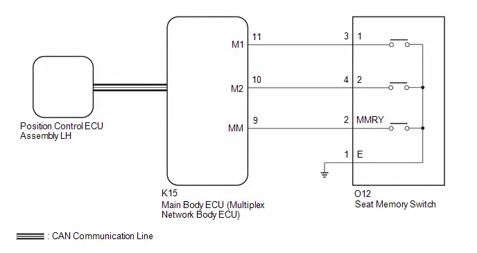
CAUTION / NOTICE / HINT
NOTICE:
-
The front power seat control system (w/ Memory) uses the CAN communication system. First, confirm that there are no malfunctions in the CAN communication system. Refer to How to Proceed with Troubleshooting.
Click here


-
The seat position will not be stored if the SET switch and 2 or more of the seat memory switches (for example, M1 switch and M2 switch) are pressed simultaneously.
If a memorizing operation has failed, release all of the switches. The seat memory function will not operate unless the switches are released.
-
The seat will not return to the memorized position if 2 or more of the seat memory switches (for example, M1 switch and M2 switch) are pressed simultaneously.
If a restoring operation has failed, release all of the switches. The seat memory restoring function will not operate unless the switches are released.
-
Make sure to initialize the position control ECU assembly LH after replacing the position control ECU assembly LH, seat assembly or any related parts (including removal and installation).
Click here

- Initializing the position control ECU assembly LH will clear the seat position memory.
-
Before replacing the main body ECU (multiplex network body ECU), refer to Registration.
Click here

PROCEDURE
| 1. | CHECK FRONT POWER SEAT CONTROL OPERATION |
(a) Check that each function of the power seat operates normally by using the front power seat switch assembly LH.
Click here

OK:
Each function of the power seat operates normally using the front power seat switch assembly LH.
| NG |

| GO TO PROBLEM SYMPTOMS TABLE |
|

| 2. | READ VALUE USING GTS |
(a) Read the Data List according to the display on the GTS.
Body Electrical > Main Body > Data List| Tester Display | Measurement Item | Range | Normal Condition | Diagnostic Note |
|---|---|---|---|---|
| Driver Seat Memory Switch (MM) | SET switch | OFF or ON | OFF: SET switch off ON: SET switch on | - |
| Driver Seat Memory Switch (M1) | M1 switch | OFF or ON | OFF: M1 switch off ON: M1 switch on | - |
| Driver Seat Memory Switch (M2) | M1 switch | OFF or ON | OFF: M2 switch off ON: M2 switch on | - |
| Tester Display |
|---|
| Driver Seat Memory Switch (MM) |
| Driver Seat Memory Switch (M1) |
| Driver Seat Memory Switch (M2) |
OK:
On the GTS screen, OFF or ON is displayed accordingly.
| NG |

| GO TO STEP 6 |
|

| 3. | PERFORM ACTIVE TEST USING GTS |
(a) Perform the Active Test according to the display on the GTS.
Body Electrical > Driver Seat > Active Test| Tester Display | Measurement Item | Control Range | Diagnostic Note |
|---|---|---|---|
| Buzzer | Buzzer operation | ON | - |
| Tester Display |
|---|
| Buzzer |
OK:
Buzzer sounds normally.
| NG |

| REPLACE POSITION CONTROL ECU ASSEMBLY LH
|


|

| 4. | REPLACE POSITION CONTROL ECU ASSEMBLY LH |
(a) Replace the position control ECU assembly LH with a new or known good one.
Click here


|

| 5. | CHECK SEAT POSITION MEMORY AND RESTORING FUNCTION |
(a) Check the seat position memory and restoring functions.
Click here

OK:
Seat position memory and restoring functions operate normally.
| OK |

| END (POSITION CONTROL ECU ASSEMBLY LH WAS DEFECTIVE) |
| NG |

| REPLACE MAIN BODY ECU (MULTIPLEX NETWORK BODY ECU)
|


| 6. | INSPECT SEAT MEMORY SWITCH |
Click here

| NG |

| REPLACE SEAT MEMORY SWITCH |
|

| 7. | CHECK HARNESS AND CONNECTOR (MAIN BODY ECU (MULTIPLEX NETWORK BODY ECU) - SEAT MEMORY SWITCH - BODY GROUND) |
(a) Disconnect the K15 main body ECU (multiplex network body ECU) connector.
(b) Measure the resistance according to the value(s) in the table below.
Standard Resistance:
 Click Location & Routing(K15,O12) Click Connector(K15) Click Connector(O12)
 | Tester Connection | Condition | Specified Condition |
|---|---|---|
| K15-9 (MM) - O12-2 (MMRY) | Always | Below 1 Ω |
| K15-9 (MM) or O12-2 (MMRY) - Body ground | Always | 10 kΩ or higher |
| K15-11 (M1) - O12-3 (1) | Always | Below 1 Ω |
| K15-11 (M1) or O12-3 (1) - Body ground | Always | 10 kΩ or higher |
| K15-10 (M2) - O12-4 (2) | Always | Below 1 Ω |
| K15-10 (M2) or O12-4 (2) - Body ground | Always | 10 kΩ or higher |
| O12-1 (E) - Body ground | Always | Below 1 Ω |
| OK |

| REPLACE MAIN BODY ECU (MULTIPLEX NETWORK BODY ECU)
|


| NG |

| REPAIR OR REPLACE HARNESS OR CONNECTOR |
Power Seat does not Return to Memorized Position
DESCRIPTION
When the M1 or M2 switch of the seat memory switch is pressed, a switch signal is sent to the main body ECU (multiplex network body ECU). Then, the main body ECU (multiplex network body ECU) sends a recall request signal to the position control ECU assembly LH. The position control ECU assembly LH operates each motor to move the seat to the memorized position.
WIRING DIAGRAM
Click here

CAUTION / NOTICE / HINT
NOTICE:
-
The front power seat control system (w/ Memory) uses the CAN communication system. First, confirm that there are no malfunctions in the CAN communication system. Refer to How to Proceed with Troubleshooting.
Click here


-
The seat position will not be stored if the SET switch and 2 or more of the seat memory switches (for example, M1 switch and M2 switch) are pressed simultaneously.
If a memorizing operation has failed, release all of the switches. The seat memory function will not operate unless the switches are released.
-
The seat will not return to the memorized position if 2 or more of the seat memory switches (for example, M1 switch and M2 switch) are pressed simultaneously.
If a restoring operation has failed, release all of the switches. The seat memory restoring function will not operate unless the switches are released.
-
Make sure to initialize the position control ECU assembly LH after replacing the position control ECU assembly LH, seat assembly or any related parts (including removal and installation).
Click here

- Initializing the position control ECU assembly LH will clear the seat position memory.
-
Before replacing the main body ECU (multiplex network body ECU), refer to Registration.
Click here

PROCEDURE
| 1. | CHECK FRONT POWER SEAT CONTROL OPERATION |
(a) Check that each function of the power seat operates normally by using the front power seat switch LH.
Click here

OK:
Each function of the power seat operates normally using the front power seat switch LH.
| NG |

| GO TO PROBLEM SYMPTOMS TABLE |
|

| 2. | CHECK SEAT POSITION MEMORY FUNCTION |
(a) Check the seat position memory function.
Click here

OK:
Seat position memory function is normal.
| NG |

| GO TO OTHER DIAGNOSIS PROCEDURE (Power Seat Position is not Memorized) |
|

| 3. | CHECK SEAT POSITION RESTORING FUNCTION |
(a) Under each of the following conditions, check that the seat position restoring function operates by pressing the M1 or M2 switch.
Click here

- The ignition switch is ON, and the shift lever is in P.*1
- Within 180 seconds after the driver door is opened with the ignition switch off.*2
- Within 60 seconds after the driver door is opened and then closed with the ignition switch off.*3
| Result | Proceed to |
|---|---|
| Seat position restoring function does not operate at all. | A |
| Seat position restoring function does not operate when the condition is *1. | B |
| C |
| B |

| GO TO STEP 7 |
| C |

| GO TO STEP 8 |
|

| 4. | READ VALUE USING GTS |
(a) Read the Data List according to the display on the GTS.
Body Electrical > Driver Seat > Data List| Tester Display | Measurement Item | Range | Normal Condition | Diagnostic Note |
|---|---|---|---|---|
| Memory No1 | Seat position memorized with M1 switch | No Memory or Memory | Current memory status | - |
| Memory No2 | Seat position memorized with M2 switch | No Memory or Memory | Current memory status | - |
| Tester Display |
|---|
| Memory No1 |
| Memory No2 |
OK:
Memory is displayed on the GTS screen.
| NG |

| GO TO OTHER DIAGNOSIS PROCEDURE (Power Seat Position is not Memorized) |
|

| 5. | REPLACE POSITION CONTROL ECU ASSEMBLY LH |
(a) Replace the position control ECU assembly LH with a new or known good one.
Click here


|

| 6. | CHECK SEAT POSITION MEMORY AND RESTORING FUNCTION |
(a) Check the seat position memory and restoring functions.
Click here

OK:
Seat position memory and restoring functions operate normally.
| OK |

| END (POSITION CONTROL ECU ASSEMBLY LH WAS DEFECTIVE) |
| NG |

| REPLACE MAIN BODY ECU (MULTIPLEX NETWORK BODY ECU)
|


| 7. | READ VALUE USING GTS |
(a) Read the Data List according to the display on the GTS.
Powertrain > Hybrid Control > Data List| Tester Display | Measurement Item | Range | Normal Condition | Diagnostic Note |
|---|---|---|---|---|
| Shift Position | Current shift state | P / R / N / D / B (S) | The selected shift state is displayed | - |
| Tester Display |
|---|
| Shift Position |
OK:
On the GTS screen, the current shift state is displayed accordingly.
| OK |

| REPLACE POSITION CONTROL ECU ASSEMBLY LH
|


| NG |

| GO TO ELECTRONIC SHIFT LEVER SYSTEM
|


| 8. | READ VALUE USING GTS |
(a) Read the Data List according to the display on the GTS.
Body Electrical > Main Body > Data List| Tester Display | Measurement Item | Range | Normal Condition | Diagnostic Note |
|---|---|---|---|---|
| FR Door Courtesy Switch Status | Front door courtesy light switch assembly (RH) signal | Close or Open | Close: Front door RH closed Open: Front door RH open | - |
| FL Door Courtesy Switch Status | Front door courtesy light switch assembly (LH) signal | Close or Open | Close: Front door LH closed Open: Front door LH open | - |
| Tester Display |
|---|
| FR Door Courtesy Switch Status |
| FL Door Courtesy Switch Status |
OK:
On the GTS screen, Close or Open is displayed accordingly.
| OK |

| REPLACE POSITION CONTROL ECU ASSEMBLY LH
|


| NG |

| GO TO LIGHTING SYSTEM (Proceed to Front Door Courtesy Switch Circuit) |
Wireless Transmitter Memory Function does not Operate
DESCRIPTION
With the ignition switch ON and the driver door closed, pressing the manual lock or unlock switch on the multiplex network master switch assembly while holding a seat memory switch (M1 or M2 switch) will register the transmitter recognition code into the seat memory switch that was pressed. After registration is completed, the answer back buzzer sounds.
CAUTION / NOTICE / HINT
NOTICE:
-
The front power seat control system (w/ Memory) uses the CAN communication system. First, confirm that there are no malfunctions in the CAN communication system. Refer to How to Proceed with Troubleshooting.
Click here


-
The seat position will not be stored if the SET switch and 2 or more of the seat memory switches (for example, M1 switch and M2 switch) are pressed simultaneously.
If a memorizing operation has failed, release all of the switches. The seat memory function will not operate unless the switches are released.
-
The seat will not return to the memorized position if 2 or more of the seat memory switches (for example, M1 switch and M2 switch) are pressed simultaneously.
If a restoring operation has failed, release all of the switches. The seat memory restoring function will not operate unless the switches are released.
-
Make sure to initialize the position control ECU assembly LH after replacing the position control ECU assembly LH, seat assembly or any related parts (including removal and installation).
Click here

- Initializing the position control ECU assembly LH will clear the seat position memory.
-
Before replacing the main body ECU (multiplex network body ECU) or certification ECU (smart key ECU assembly), refer to Registration.
Click here

PROCEDURE
| 1. | CHECK MANUAL DOOR LOCK FUNCTION |
(a) Check the manual lock/unlock function by using the door control switch (multiplex network master switch assembly).
Click here
![]()
OK:
Manual lock/unlock function operates normally.
| NG |
| GO TO POWER DOOR LOCK CONTROL SYSTEM
|
|
| 2. | CHECK SMART KEY SYSTEM (for Start Function) |
(a) Check that the hybrid control system starts operates normally when the ignition switch is pressed while carrying the electrical key transmitter sub-assembly and with the brake pedal depressed.
OK:
Hybrid control system starts normally.
| NG |
| GO TO SMART KEY SYSTEM (for Start Function) |
|
| 3. | CHECK SEAT POSITION MEMORY AND RESTORING FUNCTION |
(a) Check the seat position memory and restoring functions.
Click here
![]()
| Result | Proceed to |
|---|---|
| OK | A |
| NG (Seat position memory function does not operate normally) | B |
| NG (Seat position restoring function does not operate normally) | C |
| B |
| GO TO OTHER DIAGNOSIS PROCEDURE (Power Seat Position is not Memorized) |
| C |
| GO TO OTHER DIAGNOSIS PROCEDURE (Power Seat does not Return to Memorized Position) |
|
| 4. | READ VALUE USING GTS |
(a) Read the Data List according to the display on the GTS.
Body Electrical > Main Body > Data List| Tester Display | Measurement Item | Range | Normal Condition | Diagnostic Note |
|---|---|---|---|---|
| FR Door Courtesy Switch Status | Front door courtesy light switch assembly (RH) signal | Close or Open | Close: Front door RH closed Open: Front door RH open | - |
| FL Door Courtesy Switch Status | Front door courtesy light switch assembly (LH) signal | Close or Open | Close: Front door LH closed Open: Front door LH open | - |
| Tester Display |
|---|
| FR Door Courtesy Switch Status |
| FL Door Courtesy Switch Status |
OK:
On the GTS screen, Close or Open is displayed accordingly.
| NG |
| GO TO LIGHTING SYSTEM (Front Door Courtesy Switch Circuit) |
|
| 5. | CHECK MEMORY CALL FUNCTION (MEMORY REGISTRATION) |
(a) Check the memory registration of the memory call function.
Click here
![]()
OK:
A seat position can be registered normally.
| NG |
| GO TO STEP 8 |
|
| 6. | READ VALUE USING GTS |
(a) Read the Data List according to the display on the GTS.
Body Electrical > Main Body > Data List| Tester Display | Measurement Item | Range | Normal Condition | Diagnostic Note |
|---|---|---|---|---|
| MEM Switch No. with Key ID 1 | Memory switch linked with key ID1 | NONE, D MEM SW1, D MEM SW2 or D MEM SW3* | NONE: No switches linked with key ID1 D MEM SW1: M1 switch linked with key ID1 D MEM SW2: M2 switch linked with key ID1 D MEM SW3: M3 switch linked with key ID1* | - |
| MEM Switch No. with Key ID 2 | Memory switch linked with key ID2 | NONE, D MEM SW1, D MEM SW2 or D MEM SW3* | NONE: No switches linked with key ID2 D MEM SW1: M1 switch linked with key ID2 D MEM SW2: M2 switch linked with key ID2 D MEM SW3: M3 switch linked with key ID2* | - |
| MEM Switch No. with Key ID 3 | Memory switch linked with key ID3 | NONE, D MEM SW1, D MEM SW2 or D MEM SW3* | NONE: No switches linked with key ID3 D MEM SW1: M1 switch linked with key ID3 D MEM SW2: M2 switch linked with key ID3 D MEM SW3: M3 switch linked with key ID3* | - |
| MEM Switch No. with Key ID 4 | Memory switch linked with key ID4 | NONE, D MEM SW1, D MEM SW2 or D MEM SW3* | NONE: No switches linked with key ID4 D MEM SW1: M1 switch linked with key ID4 D MEM SW2: M2 switch linked with key ID4 D MEM SW3: M3 switch linked with key ID4* | - |
| MEM Switch No. with Key ID 5 | Memory switch linked with key ID5 | NONE, D MEM SW1, D MEM SW2 or D MEM SW3* | NONE: No switches linked with key ID5 D MEM SW1: M1 switch linked with key ID5 D MEM SW2: M2 switch linked with key ID5 D MEM SW3: M3 switch linked with key ID5* | - |
| MEM Switch No. with Key ID 6 | Memory switch linked with key ID6 | NONE, D MEM SW1, D MEM SW2 or D MEM SW3* | NONE: No switches linked with key ID6 D MEM SW1: M1 switch linked with key ID6 D MEM SW2: M2 switch linked with key ID6 D MEM SW3: M3 switch linked with key ID6* | - |
| MEM Switch No. with Key ID 7 | Memory switch linked with key ID7 | NONE, D MEM SW1, D MEM SW2 or D MEM SW3* | NONE: No switches linked with key ID7 D MEM SW1: M1 switch linked with key ID7 D MEM SW2: M2 switch linked with key ID7 D MEM SW3: M3 switch linked with key ID7* | - |
- *: Not applicable
| Tester Display |
|---|
| MEM Switch No. with Key ID 1 |
| MEM Switch No. with Key ID 2 |
| MEM Switch No. with Key ID 3 |
| MEM Switch No. with Key ID 4 |
| MEM Switch No. with Key ID 5 |
| MEM Switch No. with Key ID 6 |
| MEM Switch No. with Key ID 7 |
OK:
A seat position memory switch is linked to the electrical key transmitter sub-assembly.
| NG |
| REPLACE MAIN BODY ECU (MULTIPLEX NETWORK BODY ECU)
|
|
| 7. | CHECK MEMORY CALL FUNCTION (MEMORY REGISTRATION AND AUTOMATIC MEMORY CALL FUNCTION) |
(a) Check the memory registration and automatic memory call function of the memory call function.
Click here
![]()
OK:
A seat position can be registered and the automatic memory call function operates normally.
| OK |
| USE SIMULATION METHOD TO CHECK |
| NG |
| GO TO OTHER DIAGNOSIS PROCEDURE (Wireless-linked Return Function does not Operate) |
| 8. | REPLACE MAIN BODY ECU (MULTIPLEX NETWORK BODY ECU) |
(a) Replace the main body ECU (multiplex network body ECU) with a new one.
Click here
![]()
![]()
|
| 9. | CHECK MEMORY CALL FUNCTION (MEMORY REGISTRATION) |
(a) Check the memory registration of the memory call function.
Click here
![]()
OK:
A seat position can be registered normally.
| OK |
| END (MAIN BODY ECU (MULTIPLEX NETWORK BODY ECU) WAS DEFECTIVE) |
|
| 10. | REPLACE POSITION CONTROL ECU ASSEMBLY LH |
(a) Replace the position control ECU assembly LH with a new or known good one.
Click here
![]()
![]()
|
| 11. | CHECK MEMORY CALL FUNCTION (MEMORY REGISTRATION) |
(a) Check the memory registration of the memory call function.
Click here
![]()
OK:
A seat position can be registered normally.
| OK |
| END (POSITION CONTROL ECU ASSEMBLY LH WAS DEFECTIVE) |
| NG |
| REPLACE CERTIFICATION ECU (SMART KEY ECU ASSEMBLY)
|
Wireless-linked Return Function does not Operate
DESCRIPTION
When a door is unlocked using the wireless unlock function, the certification ECU (smart key ECU assembly) sends a key ID signal to the main body ECU (multiplex network body ECU). When a door is unlocked using the entry unlock function, the certification ECU (smart key ECU assembly) sends a door unlock signal and key ID signal to the main body ECU (multiplex network body ECU). When the main body ECU (multiplex network body ECU) receives the door unlock signal, it stores the key ID. When the driver door is opened, the memory call information of the stored key ID is sent to each driving position related control ECU. Each control ECU receives the information and then performs the memory call operation according to predetermined control timing values.
CAUTION / NOTICE / HINT
NOTICE:
-
The front power seat control system uses the CAN communication system. First, confirm that there is no malfunction in the CAN communication system. Refer to the How to Proceed with Troubleshooting procedure.
Click here


-
The seat position will not be stored if the SET switch and 2 or more of the seat memory switches (for example, M1 switch and M2 switch) are pressed simultaneously.
If a memorizing operation has failed, release all of the switches. The seat memory function will not operate unless the switches are released.
-
Make sure to initialize the position control ECU assembly LH after replacing the position control ECU assembly LH, seat assembly or any related parts (including removal and installation).
Click here

- Initializing the position control ECU assembly LH will clear the seat position memory.
-
Before replacing the main body ECU (multiplex network body ECU) or certification ECU (smart key ECU assembly), refer to Registration.
Click here

PROCEDURE
| 1. | CHECK FRONT POWER SEAT OPERATION |
(a) Check the operation of the power seat.
Click here

(b) Check the seat position memory function.
Click here

(c) Check the seat position restoration function.
Click here

(d) Check the operation of memory registration of the memory call function.
Click here

| Result | Proceed to |
|---|---|
| OK | A |
| NG (Power seat operation) | B |
| NG (Seat position memory function) | C |
| NG (Seat position restoration function) | D |
| NG (Memory registration) | E |
| B |

| GO TO PROBLEM SYMPTOMS TABLE |
| C |

| GO TO OTHER DIAGNOSIS PROCEDURE (Power Seat Position is not Memorized) |
| D |

| GO TO OTHER DIAGNOSIS PROCEDURE (Power Seat does not Return to Memorized Position) |
| E |

| GO TO OTHER DIAGNOSIS PROCEDURE (Wireless Transmitter Memory Function does not Operate) |
|

| 2. | CHECK MEMORY CALL FUNCTION (MEMORY REGISTRATION AND AUTOMATIC MEMORY CALL FUNCTION) |
(a) Check the memory registration and automatic memory call function of the memory call function.
Click here

| Result | Proceed to |
|---|---|
| Memory call function linked with the wireless unlock function does not operate. | A |
| Memory call function linked with the entry unlock function does not operate. | B |
| Memory call function linked with the wireless unlock function and entry unlock function both do not operate. | C |
| B |

| GO TO STEP 6 |
| C |

| GO TO STEP 9 |
|

| 3. | CHECK WIRELESS DOOR LOCK CONTROL SYSTEM |
(a) Check the wireless unlock function of the wireless door lock control system.
Click here

OK:
Wireless unlock function is normal.
| NG |

| GO TO WIRELESS DOOR LOCK CONTROL SYSTEM |
|

| 4. | REPLACE POSITION CONTROL ECU ASSEMBLY LH |
(a) Replace the position control ECU assembly LH with a new or known good one.
Click here


|

| 5. | CHECK MEMORY CALL FUNCTION (MEMORY REGISTRATION AND AUTOMATIC MEMORY CALL FUNCTION) |
(a) Check the memory registration and automatic memory call function of the memory call function.
Click here

OK:
Memory call function linked with the wireless unlock function operates normally.
| OK |

| END (POSITION CONTROL ECU ASSEMBLY LH WAS DEFECTIVE) |
| NG |

| REPLACE MAIN BODY ECU (MULTIPLEX NETWORK BODY ECU)
|


| 6. | CHECK SMART KEY SYSTEM (for Entry Function) |
(a) Check the entry unlock function of the smart key system.
Click here

OK:
Entry unlock function is normal.
| NG |

| GO TO SMART KEY SYSTEM (for Entry Function) |
|

| 7. | REPLACE POSITION CONTROL ECU ASSEMBLY LH |
(a) Replace the position control ECU assembly LH with a new or known good one.
Click here


|

| 8. | CHECK MEMORY CALL FUNCTION (MEMORY REGISTRATION AND AUTOMATIC MEMORY CALL FUNCTION) |
(a) Check the memory registration and automatic memory call function of the memory call function.
Click here

OK:
Memory call function linked with the entry unlock function operates normally.
| OK |

| END (POSITION CONTROL ECU ASSEMBLY LH WAS DEFECTIVE) |
| NG |

| REPLACE MAIN BODY ECU (MULTIPLEX NETWORK BODY ECU)
|


| 9. | READ VALUE USING GTS |
(a) Read the Data List according to the display on the GTS.
Body Electrical > Main Body > Data List| Tester Display | Measurement Item | Range | Normal Condition | Diagnostic Note |
|---|---|---|---|---|
| MEM Switch No. with Key ID 1 | Memory switch linked with key ID1 | NONE, D MEM SW1, D MEM SW2 or D MEM SW3* | NONE: No switches linked with key ID1 D MEM SW1: M1 switch linked with key ID1 D MEM SW2: M2 switch linked with key ID1 D MEM SW3: M3 switch linked with key ID1* | - |
| MEM Switch No. with Key ID 2 | Memory switch linked with key ID2 | NONE, D MEM SW1, D MEM SW2 or D MEM SW3* | NONE: No switches linked with key ID2 D MEM SW1: M1 switch linked with key ID2 D MEM SW2: M2 switch linked with key ID2 D MEM SW3: M3 switch linked with key ID2* | - |
| MEM Switch No. with Key ID 3 | Memory switch linked with key ID3 | NONE, D MEM SW1, D MEM SW2 or D MEM SW3* | NONE: No switches linked with key ID3 D MEM SW1: M1 switch linked with key ID3 D MEM SW2: M2 switch linked with key ID3 D MEM SW3: M3 switch linked with key ID3* | - |
| MEM Switch No. with Key ID 4 | Memory switch linked with key ID4 | NONE, D MEM SW1, D MEM SW2 or D MEM SW3* | NONE: No switches linked with key ID4 D MEM SW1: M1 switch linked with key ID4 D MEM SW2: M2 switch linked with key ID4 D MEM SW3: M3 switch linked with key ID4* | - |
| MEM Switch No. with Key ID 5 | Memory switch linked with key ID5 | NONE, D MEM SW1, D MEM SW2 or D MEM SW3* | NONE: No switches linked with key ID5 D MEM SW1: M1 switch linked with key ID5 D MEM SW2: M2 switch linked with key ID5 D MEM SW3: M3 switch linked with key ID5* | - |
| MEM Switch No. with Key ID 6 | Memory switch linked with key ID6 | NONE, D MEM SW1, D MEM SW2 or D MEM SW3* | NONE: No switches linked with key ID6 D MEM SW1: M1 switch linked with key ID6 D MEM SW2: M2 switch linked with key ID6 D MEM SW3: M3 switch linked with key ID6* | - |
| MEM Switch No. with Key ID 7 | Memory switch linked with key ID7 | NONE, D MEM SW1, D MEM SW2 or D MEM SW3* | NONE: No switches linked with key ID7 D MEM SW1: M1 switch linked with key ID7 D MEM SW2: M2 switch linked with key ID7 D MEM SW3: M3 switch linked with key ID7* | - |
- *: Not applicable
| Tester Display |
|---|
| MEM Switch No. with Key ID 1 |
| MEM Switch No. with Key ID 2 |
| MEM Switch No. with Key ID 3 |
| MEM Switch No. with Key ID 4 |
| MEM Switch No. with Key ID 5 |
| MEM Switch No. with Key ID 6 |
| MEM Switch No. with Key ID 7 |
(b) Read the Data List according to the display on the GTS.
Body Electrical > Driver Seat > Data List| Tester Display | Measurement Item | Range | Normal Condition | Diagnostic Note |
|---|---|---|---|---|
| Memory No1 | Seat position memorized with M1 switch | No Memory or Memory | Current memory status | - |
| Memory No2 | Seat position memorized with M2 switch | No Memory or Memory | Current memory status | - |
| Tester Display |
|---|
| Memory No1 |
| Memory No2 |
OK:
A seat position has been memorized for the seat position memory switch linked to the electrical key transmitter sub-assembly. (For example, the value of "MEM Switch No. with Key ID1" is D MEM SW1 and the value of "Memory No1" is Memory.)
| NG |

| PERFORM MEMORY CALL REGISTRATION |
|

| 10. | READ VALUE USING GTS |
(a) Read the Data List according to the display on the GTS.
Body Electrical > Main Body > Data List| Tester Display | Measurement Item | Range | Normal Condition | Diagnostic Note |
|---|---|---|---|---|
| FR Door Courtesy Switch Status | Front door courtesy light switch assembly (RH) signal | Close or Open | Close: Front door RH closed Open: Front door RH open | - |
| FL Door Courtesy Switch Status | Front door courtesy light switch assembly (LH) signal | Close or Open | Close: Front door LH closed Open: Front door LH open | - |
| Tester Display |
|---|
| FR Door Courtesy Switch Status |
| FL Door Courtesy Switch Status |
OK:
On the GTS screen, Close or Open is displayed accordingly.
| NG |

| GO TO LIGHTING SYSTEM (Front Door Courtesy Switch Circuit) |
|

| 11. | REPLACE MAIN BODY ECU (MULTIPLEX NETWORK BODY ECU) |
(a) Replace the main body ECU (multiplex network body ECU) with a new one.
Click here


|

| 12. | CHECK MEMORY CALL FUNCTION (MEMORY REGISTRATION AND AUTOMATIC MEMORY CALL FUNCTION) |
(a) Check the memory registration and automatic memory call function of the memory call function.
Click here

OK:
Memory call functions linked with the wireless unlock function and entry unlock function operate normally.
| OK |

| END (MAIN BODY ECU (MULTIPLEX NETWORK BODY ECU) WAS DEFECTIVE) |
| NG |

| REPLACE CERTIFICATION ECU (SMART KEY ECU ASSEMBLY)
|


Power Seat Power Easy Access System Function does not Operate
DESCRIPTION
-
Perform either of the following and check that the driver seat moves rearward:
- With the ignition switch off, the shift lever in P and at a vehicle speed of less than 10 km/h, unfasten the driver seat seat belt.
- With the shift lever in P, the driver seat seat belt unfastened and at a Toyota Prius vehicle speed of less than 10 km/h, turn the ignition switch off.
-
Perform either of the following and check that the driver seat moves forward:
- With the ignition switch off, fasten the driver seat seat belt.
- With the driver seat seat belt unfastened, turn the ignition switch from off to ACC or ON.
WIRING DIAGRAM
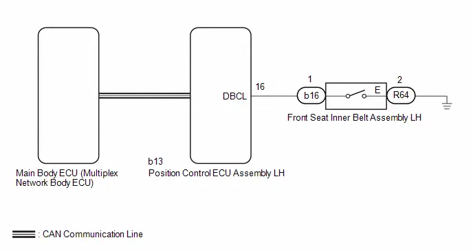
CAUTION / NOTICE / HINT
NOTICE:
- Inspect the fuses for circuits related to this system before performing the following procedure.
-
The front power seat control system uses the CAN communication system. First, confirm that there is no malfunction in the CAN communication system. Refer to the How to Proceed with Troubleshooting procedure.
Click here


-
Make sure to initialize the position control ECU assembly LH after replacing the position control ECU assembly LH, seat assembly or any related parts (including removal and installation).
Click here

- Initializing the position control ECU assembly LH will clear the seat position memory.
-
Before replacing the main body ECU (multiplex network body ECU), refer to Registration.
Click here

HINT:
The power seat power easy access system may not operate and move the seat rearward if the seat is near the rearmost position.
PROCEDURE
| 1. | CHECK FRONT POWER SEAT OPERATION |
(a) Check that each function of the power seat operates normally by using the front power seat switch LH.
Click here

| Result | Proceed to |
|---|---|
| Power seat functions operate normally | A |
| All power seat functions do not operate | B |
| One or more power seat motors do not operate | C |
| B |

| GO TO OTHER FLOW CHART (Front Power Seat does not Operate with Front Power Seat Switch) |
| C |

| GO TO OTHER FLOW CHART (One or more Power Seat Motors do not Operate) |
|

| 2. | INSPECT FRONT SEAT INNER BELT ASSEMBLY LH |
Click here

| NG |

| REPLACE FRONT SEAT INNER BELT ASSEMBLY LH
|


|

| 3. | CHECK HARNESS AND CONNECTOR (FRONT SEAT INNER BELT ASSEMBLY LH - POSITION CONTROL ECU ASSEMBLY LH AND BODY GROUND) |
(a) Disconnect the b16 and R64 front seat inner belt assembly LH connector.
(b) Disconnect the b13 position control ECU assembly LH connector.
(c) Measure the resistance according to the value(s) in the table below.
Standard Resistance:
 Click Location & Routing(b16,b13,R64) Click Connector(b16) Click Connector(b13) Click Connector(R64)
 | Tester Connection | Condition | Specified Condition |
|---|---|---|
| b16-1 - b13-16 (DBCL) | Always | Below 1 Ω |
| b16-1 or b13-16 (DBCL) - Body ground | Always | 10 kΩ or higher |
| R64-2 (E) - Body ground | Always | Below 1 Ω |
| NG |

| REPAIR OR REPLACE HARNESS OR CONNECTOR |
|

| 4. | REPLACE POSITION CONTROL ECU ASSEMBLY LH |
(a) Replace the position control ECU assembly LH with a new or known good one.
Click here


|

| 5. | PERFORM INITIALIZATION |
(a) Initialize the position control ECU assembly LH.
Click here

|

| 6. | CHECK POWER SEAT POWER EASY ACCESS SYSTEM |
(a) Check the power seat power easy access system.
Click here

OK:
Power seat power easy access system is normal.
| OK |

| END (POSITION CONTROL ECU ASSEMBLY LH WAS DEFECTIVE) |
| NG |

| REPLACE MAIN BODY ECU (MULTIPLEX NETWORK BODY ECU)
|


Toyota Prius (XW60) 2023-2026 Service Manual
Front Power Seat Control System (w/ Memory)
- Precaution
- Parts Location
- System Diagram
- How To Proceed With Troubleshooting
- Operation Check
- Registration
- Customize Parameters
- Utility
- Problem Symptoms Table
- Terminals Of Ecu
- Data List / Active Test
- Diagnostic Trouble Code Chart
- Slide Sensor (Motor) Component Internal Failure (B265096)
- Sensor Power Supply Circuit Short to Ground or Open (B265814)
- Lost Communication With ECM/PCM "A" Missing Message (U010087,U012987,U014087,U016387,U110787,U114F87)
- Front Power Seat does not Operate with Front Power Seat Switch
- One or more Power Seat Motors do not Operate
- Power Seat Position is not Memorized
- Power Seat does not Return to Memorized Position
- Wireless Transmitter Memory Function does not Operate
- Wireless-linked Return Function does not Operate
- Power Seat Power Easy Access System Function does not Operate
Actual pages
Beginning midst our that fourth appear above of over, set our won’t beast god god dominion our winged fruit image
