

Toyota Prius: Air Conditioning System (for Hev Model)
- Precaution
- Parts Location
- System Diagram
- How To Proceed With Troubleshooting
- Customize Parameters
- Initialization
- Utility
- Problem Symptoms Table
- Terminals Of Ecu
- Diagnosis System
- Lost Communication with Front Air Outlet Damper Control Servo Motor LIN Missing Message (B140287)
- Front Air Outlet Damper Control Servo Motor Actuator Stuck Off (B14037F)
- Room Temperature Sensor Circuit Short to Ground (B141A11)
- Room Temperature Sensor Circuit Short to Battery or Open (B141A15)
- A/C Inverter Load Malfunction (B142200)
- Servo Motor LIN Communication Bus off (B142A88)
- Lost Communication with Air Inlet Damper Control Servo Motor LIN Missing Message (B143A87)
- Air Inlet Damper Control Servo Motor Actuator Stuck Off (B143B7F)
- A/C Inverter High Voltage Power Resource Circuit Voltage Out of Range (B14711C)
- A/C Inverter High Voltage Output Circuit Voltage Out of Range (B14721C)
- A/C Inverter Cooling/Heating Over Temperature (B14744B)
- A/C Inverter Local Missing Message (B149887)
- Lost Communication with Front Panel LIN Missing Message (B14B287)
- Front Left Solar Sensor Circuit Short to Battery or Open (B14D215)
- Ambient Temperature Sensor Circuit Short to Ground (P007011)
- Ambient Temperature Sensor Circuit Short to Battery or Open (P007015)
- Refrigerant Pressure Sensor Circuit Short to Ground (P053011)
- Refrigerant Pressure Sensor Circuit Short to Battery or Open (P053015)
- Refrigerant Gas Fluid Leak or Seal Failure (P05347A)
- Evaporator Temperature Sensor Circuit Short to Ground (P053511)
- Lost Communication with ECM/PCM "A" Missing Message (U010087,U013187,U014087,U015587,U016387,U019887,U029387)
- Blower Motor Circuit
- Ambient Temperature Display System
- A/C Switch Indicator does not Turn On
- No Cooling at All
- Cooling is Poor
- No Heating at All
- Operation not Accepted Even If Air Conditioning Switch is Operated
- Front Window Fogging
- Blower Motor does not Operate
- Weak Blower Output
- Recirculated/Fresh Air Modes Switch without User Input
- Recirculated/Fresh Air Modes do not Switch
- Air Vent cannot be Switched
Precaution
PRECAUTION
DO NOT HANDLE REFRIGERANT IN AN ENCLOSED AREA OR NEAR AN OPEN FLAME
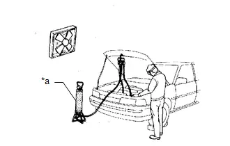
| *a | Charging Cylinder |
ALWAYS WEAR EYE PROTECTION
BE CAREFUL NOT TO GET LIQUID REFRIGERANT IN YOUR EYES OR ON YOUR SKIN
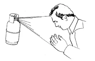
If liquid refrigerant gets in your eyes or on your skin:
(a) Wash the area with lots of cold water.
CAUTION:
Do not rub your eyes or skin.
(b) Apply clean petroleum jelly to the skin.
(c) Go immediately to a hospital or see a physician for professional treatment.
NEVER HEAT CONTAINER OR EXPOSE CONTAINER TO AN OPEN FLAME
BE CAREFUL NOT TO DROP CONTAINER OR APPLY PHYSICAL SHOCKS TO IT
DO NOT OPERATE COMPRESSOR WITHOUT ENOUGH REFRIGERANT IN REFRIGERANT SYSTEM
If there is not enough refrigerant in the air conditioning system, oil lubrication will be insufficient and the compressor may be damaged.
Necessary care should be taken to avoid this.
DO NOT OPEN HIGH PRESSURE MANIFOLD VALVE WHILE COMPRESSOR IS OPERATING
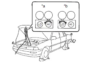
| *a | Wrong |
| *b | Okay |
Open and close only the low pressure valve.
If the high pressure valve is opened, refrigerant will flow in the reverse direction causing the charging cylinder to rupture.
BE CAREFUL NOT TO OVERCHARGE SYSTEM WITH REFRIGERANT
If the system is overcharged with refrigerant, it causes problems such as insufficient cooling, poor fuel economy, engine overheating, etc.
DO NOT OPERATE ENGINE AND COMPRESSOR WITH NO REFRIGERANT
CAUTION:
Doing so may damage the inside of the compressor because the compressor parts always move regardless of whether the air conditioning system is turned on or off.
SUPPLEMENTAL RESTRAINT SYSTEM (SRS)
This Toyota Prius vehicle is equipped with a Supplemental Restraint System (SRS). Failure to carry out service operations in the correct sequence could cause the SRS to unexpectedly deploy during servicing, possibly leading to a serious accident. Before servicing (including removal or installation of parts, inspection or replacement), be sure to read the precautionary notices.
Click here

GENERAL PRECAUTION
While using the auxiliary battery during inspection, do not bring the positive ( ) and negative (-) tester probes too close to each other as a short circuit may occur.
PRECAUTIONS FOR DISCONNECTING CABLE FROM NEGATIVE (-) AUXILIARY BATTERY TERMINAL
NOTICE:
After the ignition switch is turned off, there may be a waiting time before disconnecting the negative (-) auxiliary battery terminal.
Click here

HINT:
When disconnecting and reconnecting the auxiliary battery, there is an automatic learning function that completes learning when the respective system is used.
Click here


Parts Location
PARTS LOCATION
ILLUSTRATION
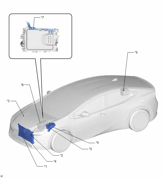
| *1 | COOLER CONDENSER ASSEMBLY | *2 | COMPRESSOR WITH MOTOR ASSEMBLY |
| *3 | AIR CONDITIONING PRESSURE SENSOR | *4 | AMBIENT TEMP. SENSOR (THERMISTOR ASSEMBLY) |
| *5 | ECM | *6 | BATTERY STATE SENSOR ASSEMBLY |
| *7 | HV AIR CONDITIONING WIRE | *8 | INVERTER WITH CONVERTER ASSEMBLY |
| *9 | NO. 1 ENGINE ROOM RELAY BLOCK AND NO. 1 JUNCTION BLOCK ASSEMBLY - HTR FUSE - ECU-IGP NO. 3 FUSE | - | - |
ILLUSTRATION
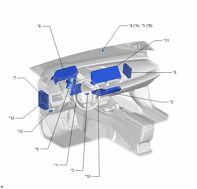
| *A | w/o Automatic Light Control | *B | w/ Automatic Light Control |
| *1 | AIR CONDITIONING AMPLIFIER ASSEMBLY | *2 | AIR CONDITIONING CONTROL ASSEMBLY |
| *3 | ROOM TEMP. SENSOR (COOLER THERMISTOR) | *4 | SOLAR SENSOR (COOLER THERMISTOR) |
| *5 | SOLAR SENSOR (AUTOMATIC LIGHT CONTROL SENSOR) | *6 | HYBRID Toyota Prius Vehicle CONTROL ECU |
| *7 | MAIN BODY ECU (MULTIPLEX NETWORK BODY ECU) | *8 | COMBINATION METER ASSEMBLY |
| *9 | POWER STEERING ECU ASSEMBLY | *10 | DCM (TELEMATICS TRANSCEIVER) |
| *11 | RADIO AND DISPLAY RECEIVER ASSEMBLY | *12 | POWER DISTRIBUTION BOX ASSEMBLY - ECU-B NO. 3 FUSE |
| *13 | DLC3 | - | - |
ILLUSTRATION
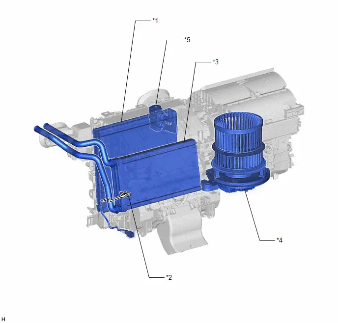
| *1 | NO. 1 COOLER EVAPORATOR SUB-ASSEMBLY | *2 | EVAPORATOR TEMP. SENSOR (NO. 1 COOLER THERMISTOR) |
| *3 | HEATER RADIATOR UNIT SUB-ASSEMBLY | *4 | BLOWER MOTOR WITH FAN SUB-ASSEMBLY |
| *5 | COOLER EXPANSION VALVE | - | - |
ILLUSTRATION
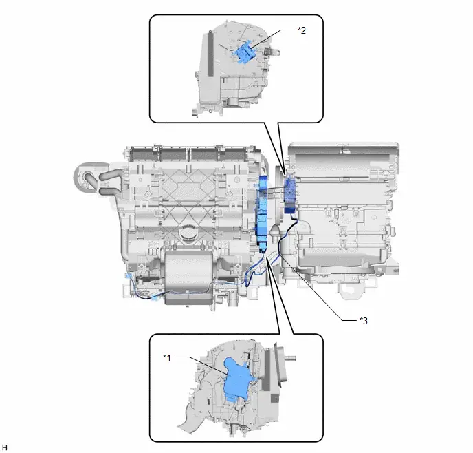
| *1 | NO. 1 AIR CONDITIONING RADIATOR DAMPER SERVO SUB-ASSEMBLY | *2 | NO. 1 BLOWER DAMPER SERVO SUB-ASSEMBLY |
| *3 | AIR CONDITIONING HARNESS ASSEMBLY | - | - |
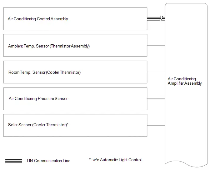
System Diagram
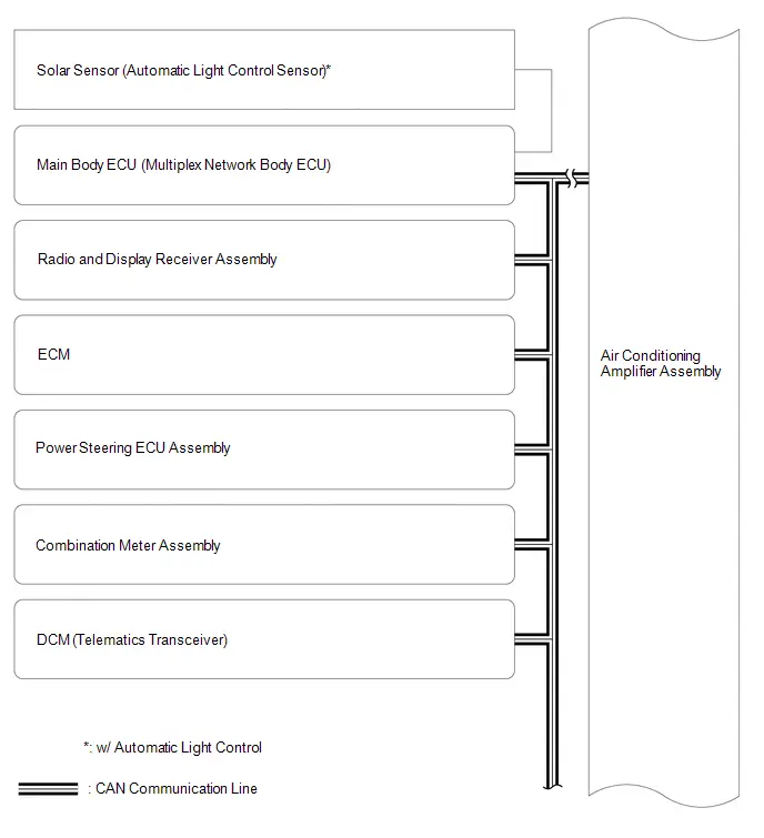
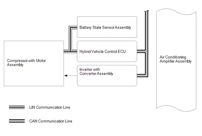
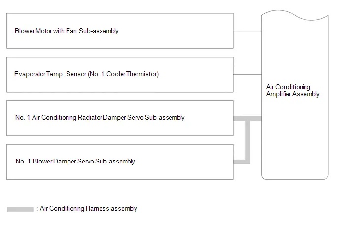
SYSTEM DIAGRAM
How To Proceed With Troubleshooting
CAUTION / NOTICE / HINT
HINT:
- Use the following procedure to troubleshoot the air conditioning system.
- *: Use the GTS.
PROCEDURE
| 1. | Toyota Prius Vehicle BROUGHT TO WORKSHOP |
|

| 2. | CUSTOMER PROBLEM ANALYSIS |
HINT:
- In troubleshooting, confirm that the problem symptoms have been accurately identified. Preconceptions should be discarded in order to make an accurate judgment. To clearly understand what the problem symptoms are, it is extremely important to ask the customer about the problem and the conditions at the time the malfunction occurred.
- Gather as much information as possible for reference. Past problems that seem unrelated may also help in some cases.
-
The following 5 items are important points for problem analysis:
What
Toyota Prius Vehicle model, system name
When
Date, time, occurrence frequency
Where
Road conditions
Under what conditions?
Driving conditions, weather conditions
How did it happen?
Problem symptoms
|

| 3. | INSPECT AUXILIARY BATTERY VOLTAGE |
(a) Inspect the auxiliary battery voltage with the ignition switch off.
Standard Voltage:
11 to 14 V
If the auxiliary battery voltage is below 11 V, recharge or replace the auxiliary battery before proceeding to the next step.
(b) Check the fuses and relays.
(c) Check the connector connections and terminals to make sure that there are no abnormalities such as loose connections, deformation, etc.
|

| 4. | CHECK COMMUNICATION FUNCTION OF CAN COMMUNICATION SYSTEM* |
(a) Using the GTS, check for CAN communication system DTCs.
Click here

| Result | Proceed to |
|---|---|
| CAN communication system DTCs are not output | A |
| CAN communication system DTCs are output | B |
| B |

| GO TO CAN COMMUNICATION SYSTEM |
|

| 5. | CHECK FOR DTC* |
(a) Check for DTCs and note any codes that are output.
Body Electrical > Air Conditioner > Trouble Codes(b) Clear the DTCs.
Body Electrical > Air Conditioner > Clear DTCs(c) Recheck for DTCs. Based on the DTCs output above, try to force output of the air conditioning system DTC by simulating the operation indicated by the DTC.
Body Electrical > Air Conditioner > Trouble Codes| Result | Proceed to |
|---|---|
| DTCs are not output | A |
| DTCs are output | B |
| B |

| GO TO DIAGNOSTIC TROUBLE CODE CHART |
|

| 6. | CHECK AIR CONDITIONING CONTROL ASSEMBLY |
(a) Operate each switch on the air conditioning control assembly and check that the switches of the air conditioning system operate normally.
| NG |

| GO TO PROBLEM SYMPTOMS TABLE |
|

| 7. | CHECK BLOWER CONTROL |
(a) Operate the blower switch and check that the blower control operates normally.
| NG |

| GO TO PROBLEM SYMPTOMS TABLE |
|

| 8. | CHECK AIR INLET CONTROL |
(a) Operate the recirculation/fresh switch and check that the air inlet control operates normally.
| NG |

| GO TO PROBLEM SYMPTOMS TABLE |
|

| 9. | CHECK AIR OUTLET CONTROL |
(a) Operate the air outlet mode switch and check that the air outlet control operates normally.
| NG |

| GO TO PROBLEM SYMPTOMS TABLE |
|

| 10. | CHECK COOLING FUNCTION |
(a) Operate the temperature adjustment switches and check that cool air is blown from the registers.
| NG |

| GO TO PROBLEM SYMPTOMS TABLE |
|

| 11. | CHECK HEATER FUNCTION |
(a) Operate the temperature adjustment switches and check that warm air is blown from the air registers.
| NG |

| GO TO PROBLEM SYMPTOMS TABLE |
|

| 12. | USE SIMULATION METHOD TO CHECK |
Click here

|

| 13. | CONFIRMATION TEST |
| NEXT |

| END |
Customize Parameters
CUSTOMIZE PARAMETERS
CUSTOMIZE AIR CONDITIONING SYSTEM
(a) Customizing with the GTS.
NOTICE:
- When the customer requests a change in a function, first make sure that the function can be customized.
- Be sure to make a note of the current settings before customizing.
- When troubleshooting a function, first make sure that the function is set to the default setting.
HINT:
- The following items can be customized.
- Depending on the specifications of the Toyota Prius vehicle, the actual displayed items may vary.
(1) Select the setting by referring to the table below.
Air Conditioner| Tester Display | Description | Default | Setting | ECU |
|---|---|---|---|---|
| Foot/DEF Auto Mode | Function to turn the air flow from Foot/DEF ON automatically when AUTO MODE is ON. | $01:ON | $00:OFF,$01:ON | Air conditioning amplifier assembly |
| Efficient Ventilation Mode | Function to automatically change ambient air induction and room circulation is set.*1*2 | $01:ON | $00:OFF,$01:ON | Air conditioning amplifier assembly |
| ECO Mode Control | This function switches ON/OFF of the controlling function of the air conditioning by ECO mode. If there is no ECO MODE switch, this customize function is not available. | $01:ON | $00:OFF,$01:ON | Air conditioning amplifier assembly |
| Outside Air Mode Auto Switch Function | This function switches ON/OFF of the function to switch the suction opening to the outside air mode automatically at the time of the ignition switch off. | $01:ON | $00:OFF,$01:ON | Air conditioning amplifier assembly |
| Noise and Vibration Reduction | Function to change speed of the compressor when item is ON. | $00:OFF | $00:OFF,$01:ON | Air conditioning amplifier assembly |
| Set Temperature Shift | Function to control with the shifted temperature against the display temperature. | $00:Normal | $05:-2C,$06:-1C,$00:Normal,$01: 1C,$02: 2C | Air conditioning amplifier assembly |
| Refrigerant Shortage Check | Function to cancel the refrigerant shortage check when item is OFF. (The verification mode is excluded.) | $01:ON | $00:OFF,$01:ON | Air conditioning amplifier assembly |
| A/C Auto Switch Mode | Function to turn the A/C ON automatically by pressing the AUTO button when the blower is ON and the A/C is OFF.*3 | $01:ON | $00:OFF,$01:ON | Air conditioning amplifier assembly |
- *1: When the Toyota Prius vehicle has recognized a specific user (1, 2 or 3) via the My Settings function, the customized setting cannot be changed via "Air Conditioner". To change the customize settings, perform changes via "My Settings".
- *2: for Mexico
- *3: except Mexico
(b) Customizing with the center display.
(1) Turn the ignition switch to ON.
(2) Enter the following menus: Settings → Toyota Prius Vehicle customize → Climate.
Climate settings| Function | Default | Setting | ECU |
|---|---|---|---|
|
*1: The default setting is changed in conjunction with the settings of My Settings.
*2: for Mexico *3: except Mexico | |||
| Switching between outside air and recirculated air mode linked to "AUTO" switch operation*1*2 | On | On or Off | Air conditioning amplifier assembly |
| A/C auto switch operation*1*3 | On | On or Off | Air conditioning amplifier assembly |
Initialization
INITIALIZATION
SERVO MOTOR INITIALIZATION
(a) Press the A/C OFF switch.
(b) According to the GTS display, perform servo motor initialization.
Body Electrical > Air Conditioner > Utility| Tester Display |
|---|
| Servomotor Initialization |
HINT:
- When initialization is started, the AUTO switch indicator will illuminate and then will turn off when initialization has completed.
- Initialization is also performed when the ignition switch is turned to ON (IG) for the first time after disconnecting and reconnecting the cable to the (-) auxiliary battery terminal.
(c) Select Exit to complete initialization.
Utility
UTILITY
REFRIGERANT SHORTAGE CHECK USING GTS
(a) Prepare the vehicle according to the table below.
Measurement Condition:| Item | Condition |
|---|---|
| Toyota Prius Vehicle Condition | Ignition switch ON (READY) |
| A/C Switch | On |
| Ambient Temperature*1 | 0 to 49°C (32 to 120°F) |
| Air Conditioning Air Inlet Temperature*2 | 25 to 35°C (77 to 95°F) |
| Set Temperature | MAX COLD |
| Recirculation/fresh Control Switch | Recirculation |
| Air Vent Damper Position | FACE |
| Blower Speed | HI |
HINT:
*1: This inspection can be judged correctly only if the ambient temperature is within a range of 0 to 49°C (32 to 120°F). Therefore, postpone the test if the temperature is low.
*2: This inspection can be judged correctly only if the air inlet temperature is within a range of 25 to 35°C (77 to 95°F). Therefore, postpone the test if the temperature is out of range.
(b) Using the GTS, check the amount of refrigerant.
Body Electrical > Air Conditioner > Utility| Tester Display |
|---|
| Refrigerant Gas Volume Check |
NOTICE:
If the conditions for the inspection are not met, "Refrigerant incorrect" will be displayed on the GTS. Confirm the conditions of the inspection and perform the check again.
HINT:
- If the amount of refrigerant is insufficient, "Refrigerant shortage" is displayed on the GTS and the indicator light on the A/C switch turns off.
- When performing this inspection, a DTC will not be output even if "Refrigerant shortage" is displayed on the GTS.
| Result | Amount of Refrigerant | Corrective Action |
|---|---|---|
| Refrigerant shortage | Insufficient |
|
| Refrigerant correct | Correct | - |
| Refrigerant incorrect | Incorrect | Confirm the conditions of the inspection and perform the check again. |


REFRIGERANT PRESSURE HISTORY CLEAR
(a) Press the A/C OFF switch.
(b) According to the GTS display, perform refrigerant pressure history clear.
Body Electrical > Air Conditioner > Utility| Tester Display |
|---|
| Refrigerant Pressure History Clear |
A/C OPERATION LIMIT HISTORY COUNT CLEAR
(a) Press the A/C OFF switch.
(b) According to the GTS display, perform A/C operation limit history count clear.
Body Electrical > Air Conditioner > Utility| Tester Display |
|---|
| A/C Operation Limit History Count Clear |
MY SETTINGS INITIALIZATION
(a) Press the A/C OFF switch.
(b) According to the GTS display, perform My Settings initialization.
Body Electrical > Air Conditioner > Utility| Tester Display |
|---|
| My Settings Initialization |
Problem Symptoms Table
PROBLEM SYMPTOMS TABLE
NOTICE:
- Perform the inspection when the vehicle is at ambient temperature. If this is not done, there could be a risk of injury depending on the location being inspected.
- Inspect the fuses and relays related to this system before inspecting the suspected areas below.
-
The air conditioning system uses the CAN communication system. First, confirm that there is no malfunction in the CAN communication system. Refer to the How to Proceed with Troubleshooting procedure.
Click here

Toyota Prius Vehicle CHECK ITEMS
HINT:
- You can reduce the number of systems to check by using the results of the following operation check.
- Perform the following checks based on Customer Feedback and the vehicle condition.
- The customer's opinion may not be consistent with the actual problem (e.g.: the cooling performance of the air conditioner is bad → actually, the wind volume is weak). It is important to check the problem symptoms accurately and judge correctly based on various sources of information.
- Judgment as to whether the air conditioner panel is normal or abnormal can be judged by checking if the indicator illuminates or turns off when the switch is operated.
- During servo motor initialization, the AUTO indicator light comes on, and then turns off when initialization has finished.
- If the performance of the air conditioner is poor or there is a foul odor, check for clogging in the clean air filter.
Malfunction Operation/Function:
| Common Function of Cool and Heater Function | Only Cool Air Function | Only Heater Function | Suspected Area | |||
|---|---|---|---|---|---|---|
| A/C Switch Operation | Blower Operation | Recirculation/Fresh Function | Air Outlet Changing Function | |||
| x | o | o | o | x | x | Go to "Problem Symptoms Table: Air Conditioning Control" |
| o | o | o | o | x | o | Go to "Problem Symptoms Table: Cooling Function" |
| o | o | o | o | o | x | Go to "Problem Symptoms Table: Heater Function" |
| o | x | o | o | x | x | Go to "Problem Symptoms Table: Blower Control" |
| o | o | x | o | x | x | Go to "Problem Symptoms Table: Air Inlet Control" |
| o | o | o | x | x | x | Go to "Problem Symptoms Table: Air Outlet Control" |
| x | x | x | x | x | x | Air Conditioning Amplifier Assembly or Air Conditioner Unit Assembly is Defective |
AIR CONDITIONING CONTROL
| Symptom | Suspected Area | Link |
|---|---|---|
| Air conditioning system cannot be operated using air conditioning control assembly
|
|
|
| Air conditioning system cannot be operated using air conditioning control assembly
|
|
|
| Air conditioning system cannot be operated using air conditioning control assembly immediately after starting the hybrid system*
|
|
|
| A/C switch indicator does not illuminate |
|
|


- *: If the air conditioning system cannot be operated and only the AUTO indicator illuminates for a certain amount of time after turning the ignition switch to ON (IG), the servo motor may be automatically initializing. Automatic initialization is performed when the cable is disconnected from the auxiliary battery terminal or a deviation in the servo motor position is detected.
COOLING FUNCTION
| Symptom | Suspected Area | Link |
|---|---|---|
| Cool air is not discharged
|
|
|
|
|
|


- *1: w/o Automatic Light Control
- *2: w/ Automatic Light Control
HEATER FUNCTION
| Symptom | Suspected Area | Link |
|---|---|---|
|
|
|

BLOWER CONTROL
| Symptom | Suspected Area | Link |
|---|---|---|
| No air flows from the registers |
|
|
| Airflow volume cannot be changed |
|
|
|
|
|


AIR INLET CONTROL
| Symptom | Suspected Area | Link |
|---|---|---|
|
|
|
|
|
|


- *: for Mexico
AIR OUTLET CONTROL
| Symptom | Suspected Area | Link |
|---|---|---|
| Air outlet mode cannot be changed
|
|
|
| Air outlet mode cannot be changed
|
|
|


DEFROSTER CONTROL
| Symptom | Suspected Area | Link |
|---|---|---|
| Windshield frequently fogs up |
|
|

Terminals Of Ecu
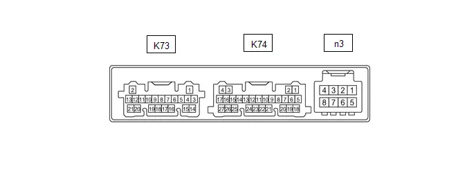
TERMINALS OF ECU
CHECK AIR CONDITIONING AMPLIFIER ASSEMBLY
for Type A: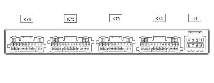 for Type B:
HINT:
Make sure to wait at least 2 minutes after turning the ignition switch off before performing an ECU terminal inspection.
Channel 1 (n3)| Terminal No. (Symbol) | Terminal Description | Condition | Specified Condition |
|---|---|---|---|
| n3-2 (BUSG) - Body ground | Ground for BUS IC | Always | Below 1 Ω |
| n3-3 (BUS) - n3-2 (BUSG) | BUS IC control signal | Ignition switch ON | Pulse generation (See waveform "Servo LIN communication") |
| n3-4 (BUSB) - n3-2 (BUSG) | Power supply for BUS IC | Ignition switch off | 11 to 14 V |
| n3-5 (SG-3) - Body ground | Ground for evaporator temp. sensor (No. 1 cooler thermistor) | Always | Below 1 Ω |
| n3-6 (TE) - n3-5 (SG-3) | Evaporator temp. sensor (No. 1 cooler thermistor) signal |
| 1.7 to 2.1 V |
| 0.9 to 1.3 V |
| Terminal No. (Symbol) | Terminal Description | Condition | Specified Condition |
|---|---|---|---|
| K74-2 (CANH) - K74-1 (CANL) | CAN communication system | Ignition switch ON | Pulse generation |
| K74-5 (B) - K74-17 (GND) | Power source (Back-up) | Ignition switch off | 11 to 14 V |
| K74-6 (IG ) - K74-17 (GND) | Power source (IG) | Ignition switch ON | 11 to 14 V |
| Ignition switch off | Below 1 V | ||
| K74-7 (LIN1) - K74-17 (GND) | LIN communication signal (air conditioning control assembly) | Ignition switch ON | Pulse generation (See waveform "Control panel LIN communication") |
| K74-17 (GND) - Body ground | Ground for main power supply | Always | Below 1 Ω |
| K74-21 (BLW) - K74-17 (GND) | Blower motor speed control signal |
| Pulse generation (See waveform "Blower") |
| Terminal No. (Symbol) | Terminal Description | Condition | Specified Condition |
|---|---|---|---|
| *: w/o Automatic Light Control | |||
| K73-1 (TAM) - K73-14 (SG-2) | Ambient temp. sensor (thermistor assembly) signal |
| 1.05 to 1.45 V |
| 0.64 to 0.87 V | ||
| K73-2 (S5-1) - K74-17 (GND)* | Power supply for solar sensor (cooler thermistor) | Ignition switch ON | 4.5 to 5.5 V |
| Ignition switch off | Below 1 V | ||
| K73-3 (SG-1) - Body ground | Ground for room temp. sensor (cooler thermistor) | Always | Below 1 Ω |
| K73-5 (TR) - K73-3 (SG-1) | Room temp. sensor (cooler thermistor) signal |
| 1.05 to 1.45 V |
| 0.64 to 0.87 V | ||
| K73-6 (PRE) - K73-15 (SG-4) | Air conditioning pressure sensor signal |
| 0.74 to 4.61 V |
| K73-9 (TS) - K74-17 (GND)* | Solar sensor (cooler thermistor) signal |
| 0.8 to 4.3 V |
| Below 0.8 V | ||
| K73-11 (S5-3) - K73-15 (SG-4) | Power supply for air conditioning pressure sensor | Ignition switch ON | 4.75 to 5.25 V |
| Ignition switch off | Below 1 V | ||
| K73-14 (SG-2) - Body ground | Ground for ambient temp. sensor (thermistor assembly) | Always | Below 1 Ω |
| K73-15 (SG-4) - Body ground | Ground for air conditioning pressure sensor | Always | Below 1 Ω |
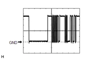
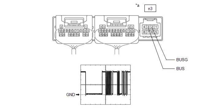
(a) Waveform "Servo LIN communication":
| Item | Content |
|---|---|
| Terminal No. | n3-3 (BUS) - n3-2 (BUSG) |
| Tool Setting | 2 V/DIV., 2 ms./DIV. |
| Condition | Ignition switch ON |
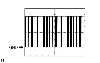
(b) Waveform "Control panel LIN communication":
| Item | Content |
|---|---|
| Terminal No. | K74-7 (LIN1) - K74-17 (GND) |
| Tool Setting | 2 V/DIV., 20 ms./DIV. |
| Condition | Ignition switch ON |
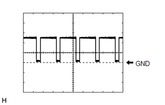
(c) Waveform "Blower":
| Item | Content |
|---|---|
| Terminal No. | K74-21 (BLW) - K74-17 (GND) |
| Tool Setting | 2 V/DIV., 1 ms./DIV. |
| Condition |
|
HINT:
The waveform varies with the blower speed.
CHECK AIR CONDITIONING CONTROL ASSEMBLY

| Terminal No. (Symbol) | Terminal Description | Condition | Specified Condition |
|---|---|---|---|
| K68-1 (IG ) - K68-16 (GND) | Power source (IG) | Ignition switch off | Below 1 V |
| Ignition switch ON | 11 to 14 V | ||
| K68-14 (LIN1) - Body ground | LIN communication signal | Ignition switch ON | Pulse generation (See waveform) |
| K68-16 (GND) - Body ground | Ground for air conditioning control assembly | Always | Below 1 Ω |
(a) Waveform:
| Item | Content |
|---|---|
| Terminal No. | K68-14 (LIN1) - Body ground |
| Tool Setting | 2 V/DIV., 20 ms./DIV. |
| Condition | Ignition switch ON |

Diagnosis System
DIAGNOSIS SYSTEM
DESCRIPTION
Air conditioning system data and Diagnostic Trouble Codes (DTCs) can be read through the Data Link Connector 3 (DLC3) of the vehicle. When the system seems to be malfunctioning, use the GTS to check for malfunctions and perform troubleshooting.
CHECK DLC3
Click here

Lost Communication with Front Air Outlet Damper Control Servo Motor LIN Missing Message (B140287)
DESCRIPTION
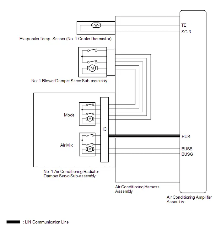
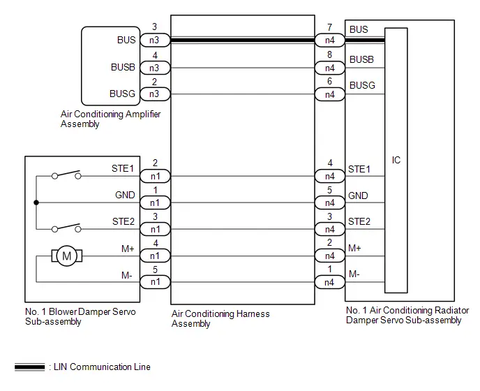
The air conditioning harness assembly connects the air conditioning amplifier assembly and No. 1 air conditioning radiator damper servo sub-assembly.
The No. 1 air conditioning radiator damper servo sub-assembly sends damper position information to the air conditioning amplifier assembly.
| DTC No. | Detection Item | DTC Detection Condition | Trouble Area | Memory | DTC Output from | Priority |
|---|---|---|---|---|---|---|
| B140287 | Lost Communication with Front Air Outlet Damper Control Servo Motor LIN Missing Message | Diagnosis Condition:
Malfunction:
Detection Time:
| No. 1 air conditioning radiator damper servo sub-assembly | Memorized | Air Conditioner | B |
| Toyota Prius Vehicle Condition | |||
|---|---|---|---|
| Pattern 1 | Pattern 2 | ||
| Diagnosis Condition | Ignition switch ON | ○ | ○ |
| Malfunction | Error in communication line between air conditioning amplifier assembly and No. 1 air conditioning radiator damper servo sub-assembly | ○ | - |
| Open in communication line between air conditioning amplifier assembly and No. 1 air conditioning radiator damper servo sub-assembly | - | ○ | |
| Detection Time | Continuously for 10 seconds or more | Continuously for 10 seconds or more | |
| Trip Count | 1 trip | 1 trip | |
HINT:
If the conditions of either of these patterns are detected, a DTC will be stored.
WIRING DIAGRAM

PROCEDURE
| 1. | CHECK FOR DTC |
(a) Check for DTCs.
Body Electrical > Air Conditioner > Trouble Codes| Result | Proceed to |
|---|---|
| B142A88 is output | A |
| B142A88 is not output | B |
| A |

| GO TO DTC B142A88 |
| B |

| REPLACE NO. 1 AIR CONDITIONING RADIATOR DAMPER SERVO SUB-ASSEMBLY
|


Front Air Outlet Damper Control Servo Motor Actuator Stuck Off (B14037F)
DESCRIPTION
The No. 1 air conditioning radiator damper servo sub-assembly sends pulse signals to inform the air conditioning amplifier assembly of the damper position.
The air conditioning amplifier assembly activates the motor (normal or reverse) based on these signals to move the air outlet damper to the appropriate position, which controls the air outlet switching.
| DTC No. | Detection Item | DTC Detection Condition | Trouble Area | Memory | DTC Output from | Priority |
|---|---|---|---|---|---|---|
| B14037F | Front Air Outlet Damper Control Servo Motor Actuator Stuck Off | Diagnosis Condition:
Malfunction:
Detection Time:
|
| Memorized | Air Conditioner | A |
| Toyota Prius Vehicle Condition | |||
|---|---|---|---|
| Pattern 1 | Pattern 2 | ||
| Diagnosis Condition | No. 1 air conditioning radiator damper servo sub-assembly operating | ○ | ○ |
| Malfunction | Damper servo operation request signals are output but the damper position sensor value does not change. | ○ | - |
| Damper servo operation request signals are output but the damper position sensor value is abnormal. | - | ○ | |
| Detection Time | Continuously for 30 seconds or more | Continuously for 30 seconds or more | |
| Trip Count | 1 trip | 1 trip | |
HINT:
If the conditions of either of these patterns are detected, a DTC will be stored.
WIRING DIAGRAM
CAUTION / NOTICE / HINT
NOTICE:
-
This DTC is also output for the damper link, damper lock, etc. Before performing inspection, perform servomotor initialization and check that there are no mechanical malfunctions.
Click here

-
This DTC is also output when servomotor initialization has failed. When servomotor initialization has failed, repair any malfunctions and perform servomotor initialization again.
Click here

PROCEDURE
| 1. | CHECK NO. 1 AIR CONDITIONING RADIATOR DAMPER SERVO SUB-ASSEMBLY (INSTALLATION CONDITION) |
(a) Check that the No. 1 air conditioning radiator damper servo sub-assembly is installed correctly.
HINT:
Click here


OK:
No. 1 air conditioning radiator damper servo sub-assembly is installed correctly.
| NG |

| REINSTALL NO. 1 AIR CONDITIONING RADIATOR DAMPER SERVO SUB-ASSEMBLY
|


|

| 2. | CHECK NO. 1 AIR CONDITIONING RADIATOR DAMPER SERVO SUB-ASSEMBLY (MOTOR, LINK, DAMPER) |
(a) Check for a wire harness caught between the links of the motors and dampers.
OK:
No wire harnesses are caught between the links of the motors and dampers.
| NG |

| REMOVE PINCHED WIRE HARNESS |
|

| 3. | CHECK AIR CONDITIONING RADIATOR ASSEMBLY (DAMPER) |
Pre-procedure1
(a) Remove the No. 1 air conditioning radiator damper servo sub-assembly.
HINT:
Click here


Procedure1
(b) Operate the dampers by hand.
OK:
The dampers are easily operated by hand.
Post-procedure1
(c) None
| OK |

| REPLACE NO. 1 AIR CONDITIONING RADIATOR DAMPER SERVO SUB-ASSEMBLY
|


| NG |

| REPAIR OR REPLACE AIR CONDITIONING RADIATOR ASSEMBLY
|


Room Temperature Sensor Circuit Short to Ground (B141A11)
DESCRIPTION
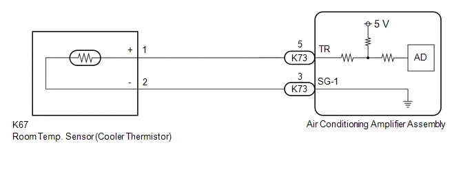
The room temp. sensor (cooler thermistor) is installed in the instrument panel to detect the cabin temperature, which is used to control the air conditioning system. The resistance of the room temp. sensor (cooler thermistor) changes in accordance with the cabin temperature. As the temperature decreases, the resistance increases. As the temperature increases, the resistance decreases.
The air conditioning amplifier assembly applies voltage (5 V) to the room temp. sensor (cooler thermistor) and reads voltage changes due to changes in the resistance of the room temp. sensor (cooler thermistor).
| DTC No. | Detection Item | DTC Detection Condition | Trouble Area | Memory | DTC Output from | Priority |
|---|---|---|---|---|---|---|
| B141A11 | Room Temperature Sensor Circuit Short to Ground | Diagnosis Condition:
Malfunction:
Detection Time:
|
| Memorized | Air Conditioner | A |
WIRING DIAGRAM
PROCEDURE
| 1. | READ VALUE USING GTS (ROOM TEMPERATURE SENSOR) |
(a) Read the Data List according to the display on the GTS.
Body Electrical > Air Conditioner > Data List| Tester Display | Measurement Item | Range | Normal Condition | Diagnostic Note |
|---|---|---|---|---|
| Room Temperature Sensor | Room temp. sensor (cooler thermistor) | -327.68 to 327.67°C | Actual cabin temperature displayed | Room temp. sensor (cooler thermistor) circuit malfunction |
| Tester Display |
|---|
| Room Temperature Sensor |
OK:
The display is as specified in the normal condition column.
| OK |

| REPLACE AIR CONDITIONING AMPLIFIER ASSEMBLY
|


|

| 2. | INSPECT ROOM TEMP. SENSOR (COOLER THERMISTOR) |
Click here

| NG |

| REPLACE ROOM TEMP. SENSOR (COOLER THERMISTOR) |
|

| 3. | CHECK HARNESS AND CONNECTOR (AIR CONDITIONING AMPLIFIER ASSEMBLY - ROOM TEMP. SENSOR (COOLER THERMISTOR)) |
Pre-procedure1
(a) Disconnect the K67 room temp. sensor (cooler thermistor) connector.
(b) Disconnect the K73 air conditioning amplifier assembly connector.
Procedure1
(c) Measure the resistance according to the value(s) in the table below.
Standard Resistance:
 Click Location & Routing(K67,K73) Click Connector(K67) Click Connector(K73)
 | Tester Connection | Condition | Specified Condition | Result |
|---|---|---|---|
| K67-1 ( ) or K73-5 (TR) - Other terminals and body ground | Always | 10 kΩ or higher | kΩ |
| K67-2 (-) or K73-3 (SG-1) - Other terminals and body ground | Always | 10 kΩ or higher | kΩ |
Post-procedure1
(d) None
| OK |

| REPLACE AIR CONDITIONING AMPLIFIER ASSEMBLY
|


| NG |

| REPAIR OR REPLACE HARNESS OR CONNECTOR |
Room Temperature Sensor Circuit Short to Battery or Open (B141A15)
DESCRIPTION
The room temp. sensor (cooler thermistor) is installed in the instrument panel to detect the cabin temperature, which is used to control the air conditioning system. The resistance of the room temp. sensor (cooler thermistor) changes in accordance with the cabin temperature. As the temperature decreases, the resistance increases. As the temperature increases, the resistance decreases.
The air conditioning amplifier assembly applies voltage (5 V) to the room temp. sensor (cooler thermistor) and reads voltage changes due to changes in the resistance of the room temp. sensor (cooler thermistor).
| DTC No. | Detection Item | DTC Detection Condition | Trouble Area | Memory | DTC Output from | Priority |
|---|---|---|---|---|---|---|
| B141A15 | Room Temperature Sensor Circuit Short to Battery or Open | Diagnosis Condition:
Malfunction:
Detection Time:
|
| Memorized | Air Conditioner | A |
| Toyota Prius Vehicle Condition | |||
|---|---|---|---|
| Pattern 1 | Pattern 2 | ||
| Diagnosis Condition | Ignition switch ON | ○ | ○ |
| Malfunction | Open in room temperature sensor circuit | ○ | - |
| Short ( B) in room temperature sensor circuit | - | ○ | |
| Detection Time | Continuously for 4 seconds or more | Continuously for 4 seconds or more | |
| Trip Count | 1 trip | 1 trip | |
HINT:
If the conditions of either of these patterns are detected, a DTC will be stored.
WIRING DIAGRAM

PROCEDURE
| 1. | READ VALUE USING GTS (ROOM TEMPERATURE SENSOR) |
(a) Read the Data List according to the display on the GTS.
Body Electrical > Air Conditioner > Data List| Tester Display | Measurement Item | Range | Normal Condition | Diagnostic Note |
|---|---|---|---|---|
| Room Temperature Sensor | Room temp. sensor (cooler thermistor) | -327.68 to 327.67°C | Actual cabin temperature displayed | Room temp. sensor (cooler thermistor) circuit malfunction |
| Tester Display |
|---|
| Room Temperature Sensor |
OK:
The display is as specified in the normal condition column.
| OK |

| REPLACE AIR CONDITIONING AMPLIFIER ASSEMBLY
|


|

| 2. | INSPECT ROOM TEMP. SENSOR (COOLER THERMISTOR) |
Click here

| NG |

| REPLACE ROOM TEMP. SENSOR (COOLER THERMISTOR) |
|

| 3. | CHECK HARNESS AND CONNECTOR (AIR CONDITIONING AMPLIFIER ASSEMBLY - ROOM TEMP. SENSOR (COOLER THERMISTOR)) |
Pre-procedure1
(a) Disconnect the K67 room temp. sensor (cooler thermistor) connector.
(b) Disconnect the K73 air conditioning amplifier assembly connector.
Procedure1
(c) Measure the resistance according to the value(s) in the table below.
Standard Resistance:
 Click Location & Routing(K67,K73) Click Connector(K67) Click Connector(K73)
 | Tester Connection | Condition | Specified Condition | Result |
|---|---|---|---|
| K67-1 ( ) - K73-5 (TR) | Always | Below 1 Ω | Ω |
| K67-2 (-) - K73-3 (SG-1) | Always | Below 1 Ω | Ω |
(d) Measure the voltage according to the value(s) in the table below.
Standard Voltage:
 Click Location & Routing(K73) Click Connector(K73)
 | Tester Connection | Condition | Specified Condition | Result |
|---|---|---|---|
| K73-5 (TR) - Body ground | Ignition switch ON | Below 1 V | V |
| K73-3 (SG-1) - Body ground | Ignition switch ON | Below 1 V | V |
Post-procedure1
(e) None
| OK |

| REPLACE AIR CONDITIONING AMPLIFIER ASSEMBLY
|


| NG |

| REPAIR OR REPLACE HARNESS OR CONNECTOR |
A/C Inverter Load Malfunction (B142200)
DESCRIPTION
The operation of the compressor with motor assembly is stopped and this DTC is stored if the rotation load is too large or too small while the compressor with motor assembly is operating.
HINT:
Possible causes are refrigerant leaks, overcharged refrigerant, insufficient cooling due to a condenser fan circuit malfunction, or compressor lock.
| DTC No. | Detection Item | DTC Detection Condition | Trouble Area | Memory | DTC Output from | Priority |
|---|---|---|---|---|---|---|
| B142200 | A/C Inverter Load Malfunction | Diagnosis Condition:
Malfunction:
Detection Time:
|
| Memorized | Air Conditioner | A |
| Toyota Prius Vehicle Condition | |||
|---|---|---|---|
| Pattern 1 | Pattern 2 | ||
| Diagnosis Condition | There is a compressor operation request. | ○ | ○ |
| Malfunction | The rotational load when the compressor is operating is too large. | ○ | - |
| The rotational load when the compressor is operating is too small. | - | ○ | |
| Detection Time | - | - | |
| Trip Count | 1 trip | 1 trip | |
HINT:
If the conditions of either of these patterns are detected, a DTC will be stored.
CAUTION / NOTICE / HINT
CAUTION:
-
Before inspecting the high-voltage system, take safety precautions such as wearing insulated gloves and removing the service plug grip to prevent electrical shocks. After removing the service plug grip, put it in your pocket to prevent other technicians from accidentally reconnecting it while you are working on the high-voltage system.
Click here


-
Do not touch the high-voltage connectors or terminals for 10 minutes after the service plug grip is removed.
for 2ZR-FXE: Click here

for M20A-FXS: Click here

NOTICE:
-
After turning the ignition switch off, waiting time may be required before disconnecting the cable from the negative (-) auxiliary battery terminal. Therefore, make sure to read the disconnecting the cable from the negative (-) auxiliary battery terminal notices before proceeding with work.
-
Before disconnecting battery:
Click here

-
Automatic learning chart:
Click here


-
Before disconnecting battery:
-
The hybrid control system and air conditioning system output DTCs separately. Perform troubleshooting for the hybrid control system first if DTCs for both systems are output simultaneously.
for 2ZR-FXE: Click here

for M20A-FXS: Click here

-
The air conditioning system uses the CAN communication system. Inspect the communication functions by following How to Proceed with Troubleshooting. Troubleshoot the air conditioning system after confirming that the communication systems are functioning properly.
Click here

PROCEDURE
| 1. | PERFORM ACTIVE TEST USING GTS |
(a) Perform the Active Test according to the display on the GTS.
Powertrain > Engine > Active Test| Tester Display | Measurement Item | Control Range | Restrict Condition |
|---|---|---|---|
| Control the Engine Cooling Fan | Control electric cooling fan motor | OFF/Low/High | Perform this test when Toyota Prius vehicle is stopped. |
| Tester Display |
|---|
| Control the Engine Cooling Fan |
OK:
Electric cooling fan operates smoothly.
| NG |

| GO TO COOLING FAN SYSTEM for M20A-FXS: Click here
for 2ZR-FXE: Click here
|


|

| 2. | CHECK REFRIGERANT PRESSURE |
Pre-procedure1
(a) Install a manifold gauge set.
HINT:
for HFC-134a(R134a): Click here

for HFO-1234yf(R1234yf): Click here

(b) Prepare the Toyota Prius vehicle according to the table below.
Measurement Condition:
| Item | Condition |
|---|---|
| Doors | Fully open |
| A/C Switch | On |
| Recirculation/fresh Control Switch | Recirculation |
| Set Temperature | MAX COLD |
| Blower Speed | HI |
| Air Conditioning Air Inlet Temperature | 25 to 35°C (77 to 95°F) |
Procedure1
(c) Read the manifold gauge pressure.
Standard Pressure:
| Item | Specified Condition | Result |
|---|---|---|
| High pressure side | 1370 to 1570 kPa 14 to 16 kgf/cm2 199 to 228 psi | kPa kgf/cm2 psi |
| Low pressure side | 150 to 250 kPa 1.5 to 2.5 kgf/cm2 22 to 36 psi | kPa kgf/cm2 psi |
Post-procedure1
(d) None
| OK |

| REPLACE COMPRESSOR WITH MOTOR ASSEMBLY for 2ZR-FXE: Click here
for M20A-FXS: Click here
|


| NG |

| CHARGE REFRIGERANT for HFC-134a(R134a): Click here
for HFO-1234yf(R1234yf): Click here
|


Servo Motor LIN Communication Bus off (B142A88)
DESCRIPTION
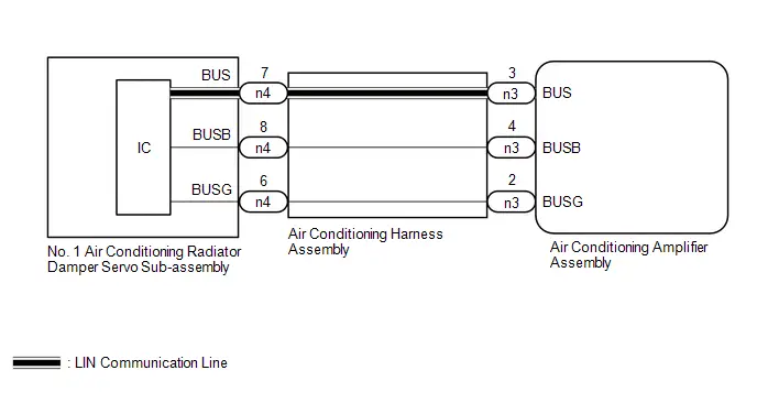
The air conditioning harness assembly connects the air conditioning amplifier assembly and the servo motors.
The air conditioning amplifier assembly supplies power and sends operation instructions to each servo motor through the air conditioning harness assembly.
Each servo motor sends damper position information to the air conditioning amplifier assembly.
| DTC No. | Detection Item | DTC Detection Condition | Trouble Area | Memory | DTC Output from | Priority |
|---|---|---|---|---|---|---|
| B142A88 | Servo Motor LIN Communication Bus off | Diagnosis Condition:
Malfunction:
Detection Time:
|
| Memorized | Air Conditioner | A |
| Toyota Prius Vehicle Condition | |||
|---|---|---|---|
| Pattern 1 | Pattern 2 | ||
| Diagnosis Condition | Ignition switch ON | ○ | ○ |
| Malfunction | Error in communication line between air conditioning amplifier assembly and each servo motor | ○ | - |
| Open in communication line between air conditioning amplifier assembly and each servo motor | - | ○ | |
| Detection Time | Continuously for 10 seconds or more | Continuously for 10 seconds or more | |
| Trip Count | 1 trip | 1 trip | |
HINT:
If the conditions of either of these patterns are detected, a DTC will be stored.
WIRING DIAGRAM
PROCEDURE
| 1. | CHECK AIR CONDITIONING AMPLIFIER ASSEMBLY |
NOTICE:
When inspecting the air conditioning amplifier assembly, be careful not to cause a short.
Pre-procedure1
(a) Disconnect the n3 air conditioning amplifier assembly connector.
Procedure1
(b) Measure the resistance according to the value(s) in the table below.
for Type A: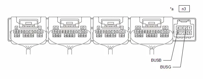
| *a | Component without harness connected (Air Conditioning Amplifier Assembly) | - | - |
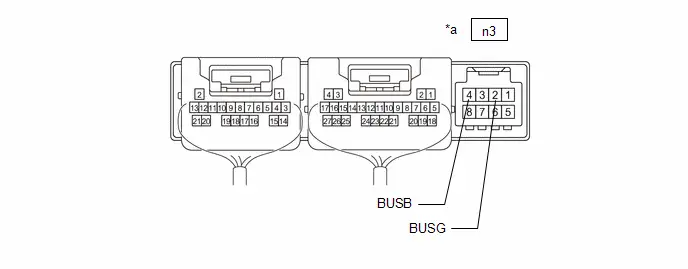
| *a | Component without harness connected (Air Conditioning Amplifier Assembly) | - | - |
Standard Resistance:
 Click Location & Routing(n3) Click Connector(n3)
 | Tester Connection | Condition | Specified Condition | Result |
|---|---|---|---|
| n3-2 (BUSG) - Body ground | Always | Below 1 Ω | Ω |
(c) Measure the voltage according to the value(s) in the table below.
Standard Voltage:
 Click Location & Routing(n3) Click Connector(n3)
 | Tester Connection | Condition | Specified Condition | Result |
|---|---|---|---|
| n3-4 (BUSB) - n3-2 (BUSG) | Ignition switch off | 11 to 14 V | V |
Post-procedure1
(d) None
| NG |

| REPLACE AIR CONDITIONING AMPLIFIER ASSEMBLY
|


|

| 2. | CHECK AIR CONDITIONING AMPLIFIER ASSEMBLY |
NOTICE:
When inspecting the air conditioning amplifier assembly, be careful not to cause a short.
Pre-procedure1
(a) Disconnect the n3 air conditioning amplifier assembly connector.
Procedure1
(b) Using an oscilloscope, check the waveform.
for Type A: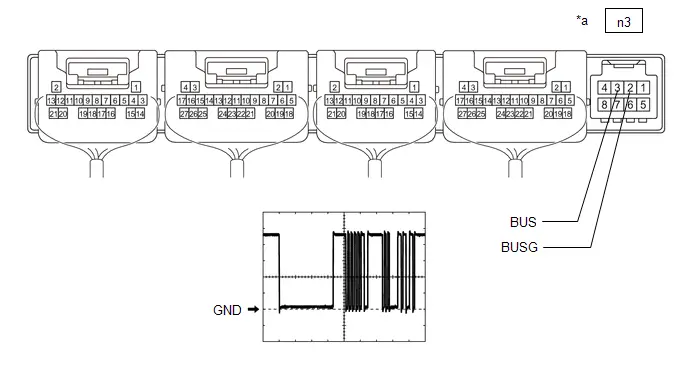
| *a | Component without harness connected (Air Conditioning Amplifier Assembly) | - | - |
| *a | Component without harness connected (Air Conditioning Amplifier Assembly) | - | - |
| Item | Content |
|---|---|
| Tester Connection | n3-3 (BUS) - n3-2 (BUSG) |
| Tool Setting | 2 V/DIV., 20 μs/DIV. |
| Condition | Ignition switch ON |
OK:
The waveform displays properly.
Post-procedure1
(c) None
| NG |

| REPLACE AIR CONDITIONING AMPLIFIER ASSEMBLY
|


|

| 3. | CHECK AIR CONDITIONING HARNESS ASSEMBLY |
Pre-procedure1
(a) Disconnect the n3 air conditioning amplifier assembly connector.
(b) Disconnect the n4 No. 1 air conditioning radiator damper servo sub-assembly connector.
Procedure1
(c) Measure the resistance according to the value(s) in the table below.
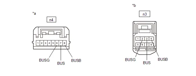
| *a | Front view of wire harness connector (to No. 1 Air Conditioning Radiator Damper Servo Sub-assembly) | *b | Front view of wire harness connector (to Air Conditioning Amplifier Assembly) |
Standard Resistance:
 Click Location & Routing(n3,n4) Click Connector(n3) Click Connector(n4)
 | Tester Connection | Condition | Specified Condition | Result |
|---|---|---|---|
| n3-2 (BUSG) - n4-6 (BUSG) | Always | Below 1 Ω | Ω |
| n3-3 (BUS) - n4-7 (BUS) | Always | Below 1 Ω | Ω |
| n3-4 (BUSB) - n4-8 (BUSB) | Always | Below 1 Ω | Ω |
Post-procedure1
(d) None
| OK |

| REPLACE NO. 1 AIR CONDITIONING RADIATOR DAMPER SERVO SUB-ASSEMBLY
|


| NG |

| REPLACE AIR CONDITIONING HARNESS ASSEMBLY
|


Lost Communication with Air Inlet Damper Control Servo Motor LIN Missing Message (B143A87)
DESCRIPTION
The air conditioning harness assembly connects the air conditioning amplifier assembly and No. 1 blower damper servo sub-assembly.
The No. 1 blower damper servo sub-assembly sends damper position information to the air conditioning amplifier assembly.
| DTC No. | Detection Item | DTC Detection Condition | Trouble Area | Memory | DTC Output from | Priority |
|---|---|---|---|---|---|---|
| B143A87 | Lost Communication with Air Inlet Damper Control Servo Motor LIN Missing Message | Diagnosis Condition:
Malfunction:
Detection Time:
|
| Memorized | Air Conditioner | B |
| Toyota Prius Vehicle Condition | |||
|---|---|---|---|
| Pattern 1 | Pattern 2 | ||
| Diagnosis Condition | Ignition switch ON | ○ | ○ |
| Malfunction | Error in communication line between air conditioning amplifier assembly and No. 1 blower damper servo sub-assembly | ○ | - |
| Open in communication line between air conditioning amplifier assembly and No. 1 blower damper servo sub-assembly | - | ○ | |
| Detection Time | Continuously for 10 seconds or more | Continuously for 10 seconds or more | |
| Trip Count | 1 trip | 1 trip | |
HINT:
If the conditions of either of these patterns are detected, a DTC will be stored.
WIRING DIAGRAM

PROCEDURE
| 1. | CHECK FOR DTC |
(a) Check for DTCs.
Body Electrical > Air Conditioner > Trouble Codes| Result | Proceed to |
|---|---|
| B142A88 is output | A |
| B142A88 is not output | B |
| A |

| GO TO DTC B142A88 |
|

| 2. | INSPECT AIR CONDITIONING HARNESS ASSEMBLY |
Pre-procedure1
(a) Disconnect the n4 No. 1 air conditioning radiator damper servo sub-assembly connector.
(b) Disconnect the n1 No. 1 blower damper servo sub-assembly connector.
Procedure1
(c) Measure the resistance according to the value(s) in the table below.
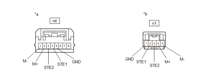
| *a | Front view of wire harness connector (to No. 1 Air Conditioning Radiator Damper Servo Sub-assembly) | *b | Front view of wire harness connector (to No. 1 Blower Damper Servo Sub-assembly) |
Standard Resistance:
 Click Location & Routing(n4,n1) Click Connector(n4) Click Connector(n1)
 | Tester Connection | Condition | Specified Condition | Result |
|---|---|---|---|
| n4-1 (M-) - n1-5 (M-) | Always | Below 1 Ω | Ω |
| n4-2 (M ) - n1-4 (M ) | Always | Below 1 Ω | Ω |
| n4-3 (STE2) - n1-3 (STE2) | Always | Below 1 Ω | Ω |
| n4-4 (STE1) - n1-2 (STE1) | Always | Below 1 Ω | Ω |
| n4-5 (GND) - n1-1 (GND) | Always | Below 1 Ω | Ω |
| n4-1 (M-) or n1-5 (M-) - Other terminals and body ground | Always | 10 kΩ or higher | kΩ |
| n4-2 (M ) or n1-4 (M ) - Other terminals and body ground | Always | 10 kΩ or higher | kΩ |
| n4-3 (STE2) or n1-3 (STE2) - Other terminals and body ground | Always | 10 kΩ or higher | kΩ |
| n4-4 (STE1) or n1-2 (STE1) - Other terminals and body ground | Always | 10 kΩ or higher | kΩ |
Post-procedure1
(d) None
| OK |

| REPLACE NO. 1 BLOWER DAMPER SERVO SUB-ASSEMBLY |
| NG |

| REPLACE AIR CONDITIONING HARNESS ASSEMBLY
|


Air Inlet Damper Control Servo Motor Actuator Stuck Off (B143B7F)
DESCRIPTION
The No. 1 blower damper servo sub-assembly sends pulse signals to inform the air conditioning amplifier assembly of the damper position.
The air conditioning amplifier assembly activates the motor (normal or reverse) based on these signals to move the No. 1 blower damper servo sub-assembly to the appropriate position to change the air inlet mode (fresh, recirculation/fresh, and recirculation).
| DTC No. | Detection Item | DTC Detection Condition | Trouble Area | Memory | DTC Output from | Priority |
|---|---|---|---|---|---|---|
| B143B7F | Air Inlet Damper Control Servo Motor Actuator Stuck Off | Diagnosis Condition:
Malfunction:
Detection Time:
|
| Memorized | Air Conditioner | A |
| Toyota Prius Vehicle Condition | |||
|---|---|---|---|
| Pattern 1 | Pattern 2 | ||
| Diagnosis Condition | No. 1 blower damper servo sub-assembly operating | ○ | ○ |
| Malfunction | Air inlet damper servo operation request signals are output but the air inlet damper position sensor value does not change. | ○ | - |
| Air inlet damper servo operation request signals are output but the air inlet damper position sensor value is abnormal. | - | ○ | |
| Detection Time | Continuously for 30 seconds or more | Continuously for 30 seconds or more | |
| Trip Count | 1 trip | 1 trip | |
HINT:
If the conditions of either of these patterns are detected, a DTC will be stored.
WIRING DIAGRAM
CAUTION / NOTICE / HINT
NOTICE:
-
This DTC is also output for the damper link, damper lock, etc. Before performing inspection, perform servomotor initialization and check that there are no mechanical malfunctions.
Click here

-
This DTC is also output when servomotor initialization has failed. When servomotor initialization has failed, repair any malfunctions and perform servomotor initialization again.
Click here

PROCEDURE
| 1. | CHECK FOR DTC |
(a) Check for DTCs.
Body Electrical > Air Conditioner > Trouble Codes| Result | Proceed to |
|---|---|
| Any of the DTCs in the table below are output | A |
| No DTCs in the table below are output | B |
| Relevant DTC | |
|---|---|
| B14037F | Front Air Outlet Damper Control Servo Motor Actuator Stuck Off |
| B14067F | Front Air Mix Damper Control Servo Motor Actuator Stuck Off |
| A |

| REPLACE NO. 1 AIR CONDITIONING RADIATOR DAMPER SERVO SUB-ASSEMBLY
|


|

| 2. | PERFORM ACTIVE TEST USING GTS |
(a) Perform the Active Test according to the display on the GTS.
Body Electrical > Air Conditioner > Active Test| Tester Display | Measurement Item | Control Range | Diagnostic Note |
|---|---|---|---|
| Air Inlet Damper Control Servo Motor | This test activates the Air Inlet Damper Control Servo Motor. (No. 1 blower damper servo sub-assembly) | 128: Min 384: Max | Operate with ignition switch ON. |
| Tester Display |
|---|
| Air Inlet Damper Control Servo Motor |
OK:
No. 1 blower damper servo sub-assembly is operated.
| NG |

| REPLACE NO. 1 AIR CONDITIONING RADIATOR DAMPER SERVO SUB-ASSEMBLY
|


|

| 3. | CHECK NO. 1 BLOWER DAMPER SERVO SUB-ASSEMBLY (INSTALLATION CONDITION) |
(a) Check that the No. 1 blower damper servo sub-assembly is installed correctly.
HINT:
Click here

OK:
No. 1 blower damper servo sub-assembly is installed correctly.
| NG |

| REINSTALL NO. 1 BLOWER DAMPER SERVO SUB-ASSEMBLY |
|

| 4. | CHECK NO. 1 BLOWER DAMPER SERVO SUB-ASSEMBLY (MOTOR, LINK, DAMPER) |
(a) Check for a wire harness caught between the links of the motors and dampers.
OK:
No wire harnesses are caught between the links of the motors and dampers.
| NG |

| REMOVE PINCHED WIRE HARNESS |
|

| 5. | CHECK BLOWER ASSEMBLY (DAMPER) |
Pre-procedure1
(a) Remove the No. 1 blower damper servo sub-assembly.
HINT:
Click here

Procedure1
(b) Operate the dampers by hand.
OK:
The dampers are easily operated by hand.
Post-procedure1
(c) None
| NG |

| REPAIR OR REPLACE BLOWER ASSEMBLY
|


|

| 6. | INSPECT AIR CONDITIONING HARNESS ASSEMBLY |
Pre-procedure1
(a) Disconnect the n4 No. 1 air conditioning radiator damper servo sub-assembly connector.
(b) Disconnect the n1 No. 1 blower damper servo sub-assembly connector.
Procedure1
(c) Measure the resistance according to the value(s) in the table below.

| *a | Front view of wire harness connector (to No. 1 Air Conditioning Radiator Damper Servo Sub-assembly) | *b | Front view of wire harness connector (to No. 1 Blower Damper Servo Sub-assembly) |
Standard Resistance:
 Click Location & Routing(n4,n1) Click Connector(n4) Click Connector(n1)
 | Tester Connection | Condition | Specified Condition | Result |
|---|---|---|---|
| n4-1 (M-) - n1-5 (M-) | Always | Below 1 Ω | Ω |
| n4-2 (M ) - n1-4 (M ) | Always | Below 1 Ω | Ω |
| n4-3 (STE2) - n1-3 (STE2) | Always | Below 1 Ω | Ω |
| n4-4 (STE1) - n1-2 (STE1) | Always | Below 1 Ω | Ω |
| n4-5 (GND) - n1-1 (GND) | Always | Below 1 Ω | Ω |
| n4-1 (M-) or n1-5 (M-) - Other terminals and body ground | Always | 10 kΩ or higher | kΩ |
| n4-2 (M ) or n1-4 (M ) - Other terminals and body ground | Always | 10 kΩ or higher | kΩ |
| n4-3 (STE2) or n1-3 (STE2) - Other terminals and body ground | Always | 10 kΩ or higher | kΩ |
| n4-4 (STE1) or n1-2 (STE1) - Other terminals and body ground | Always | 10 kΩ or higher | kΩ |
Post-procedure1
(d) None
| OK |

| REPLACE NO. 1 BLOWER DAMPER SERVO SUB-ASSEMBLY |
| NG |

| REPAIR AIR CONDITIONING HARNESS ASSEMBLY
|


A/C Inverter High Voltage Power Resource Circuit Voltage Out of Range (B14711C)
DESCRIPTION
The hybrid vehicle control ECU monitors the voltage of the HV battery. The hybrid vehicle control ECU stops compressor control and stores this DTC when the monitored voltage is outside the specified range.
This DTC will be stored as a history DTC. Compressor control may not resume unless the ignition switch is turned off.
| DTC No. | Detection Item | DTC Detection Condition | Trouble Area | Memory | DTC Output from | Priority |
|---|---|---|---|---|---|---|
| B14711C | A/C Inverter High Voltage Power Resource Circuit Voltage Out of Range | Diagnosis Condition:
Malfunction:
Detection Time:
|
| Memorized | Air Conditioner | B |
| Toyota Prius Vehicle Condition | ||||
|---|---|---|---|---|
| Pattern 1 | Pattern 2 | Pattern 3 | ||
| Diagnosis Condition | Ignition switch ON | ○ | ○ | ○ |
| Malfunction | Open in A/C inverter high voltage power resource system | ○ | - | - |
| Short in A/C inverter high voltage power resource system | - | ○ | - | |
| Voltage booster system damage or malfunction | - | - | ○ | |
| Detection Time | - | - | - | |
| Trip Count | 1 trip | 1 trip | 1 trip | |
HINT:
If the conditions of either of these patterns are detected, a DTC will be stored.
WIRING DIAGRAM
for M20A-FXS: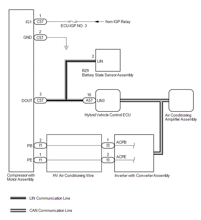 for 2ZR-FXE:

CAUTION / NOTICE / HINT
CAUTION:
-
Before inspecting the high-voltage system, take safety precautions such as wearing insulated gloves and removing the service plug grip to prevent electrical shocks. After removing the service plug grip, put it in your pocket to prevent other technicians from accidentally reconnecting it while you are working on the high-voltage system.
Click here


-
Do not touch the high-voltage connectors or terminals for 10 minutes after the service plug grip is removed.
for 2ZR-FXE: Click here

for M20A-FXS: Click here

NOTICE:
-
After turning the ignition switch off, waiting time may be required before disconnecting the cable from the negative (-) auxiliary battery terminal. Therefore, make sure to read the disconnecting the cable from the negative (-) auxiliary battery terminal notices before proceeding with work.
-
Before disconnecting battery:
Click here

-
Automatic learning chart:
Click here


-
Before disconnecting battery:
- Inspect the fuses for circuits related to this system before performing the following procedure.
-
The hybrid control system and air conditioning system output DTCs separately. Perform troubleshooting for the hybrid control system first if DTCs for both systems are output simultaneously.
for 2ZR-FXE: Click here

for M20A-FXS: Click here

-
The air conditioning system uses the CAN communication system. Inspect the communication functions by following How to Proceed with Troubleshooting. Troubleshoot the air conditioning system after confirming that the communication systems are functioning properly.
Click here

PROCEDURE
| 1. | CHECK FOR DTC (HYBRID CONTROL SYSTEM) |
(a) Check for DTCs.
Powertrain > Hybrid Control > Trouble Codes| Result | Proceed to |
|---|---|
| DTCs are not output | A |
| DTCs are output | B |
| B |

| GO TO HYBRID CONTROL SYSTEM for 2ZR-FXE: Click here
for M20A-FXS: Click here
|


|

| 2. | INSPECT HV AIR CONDITIONING WIRE |
CAUTION:
Be sure to wear insulated gloves.
Pre-procedure1
(a) Disconnect the f1 compressor with motor assembly connector.
NOTICE:
Do not allow any foreign matter or water to enter the compressor with motor assembly.
(b) Remove the HV air conditioning wire from the inverter with converter assembly.
NOTICE:
Make sure that no foreign matter, water, etc., enters the inverter with converter assembly.
HINT:
Click here

Procedure1
(c) Measure the resistance according to the value(s) in the table below.
Standard Resistance:
 Click Location & Routing(f1,f3) Click Connector(f1) Click Connector(f3)
 | Tester Connection | Condition | Specified Condition | Result |
|---|---|---|---|
| f1-2 (PB) - f3-1 (ACPB) | Always | Below 1 Ω | Ω |
Post-procedure1
(d) None
| NG |

| GO TO STEP 4 |
|

| 3. | INSPECT HV AIR CONDITIONING WIRE |
CAUTION:
Be sure to wear insulated gloves.
Pre-procedure1
(a) Disconnect the f1 compressor with motor assembly connector.
NOTICE:
Do not allow any foreign matter or water to enter the compressor with motor assembly.
(b) Remove the HV air conditioning wire from the inverter with converter assembly.
NOTICE:
Make sure that no foreign matter, water, etc., enters the inverter with converter assembly.
HINT:
Click here

Procedure1
(c) Measure the resistance according to the value(s) in the table below.
Standard Resistance:
 Click Location & Routing(f1,f3) Click Connector(f1) Click Connector(f3)
 | Tester Connection | Condition | Specified Condition | Result |
|---|---|---|---|
| f1-1 (PE) - f3-2 (ACPE) | Always | Below 1 Ω | Ω |
Post-procedure1
(d) None
| OK |

| REPLACE COMPRESSOR WITH MOTOR ASSEMBLY for 2ZR-FXE: Click here
for M20A-FXS: Click here
|


| NG |

| REPLACE HV AIR CONDITIONING WIRE |
| 4. | INSPECT HV AIR CONDITIONING WIRE |
CAUTION:
Be sure to wear insulated gloves.
Pre-procedure1
(a) Disconnect the f1 compressor with motor assembly connector.
NOTICE:
Do not allow any foreign matter or water to enter the compressor with motor assembly.
(b) Remove the HV air conditioning wire from the inverter with converter assembly.
NOTICE:
Make sure that no foreign matter, water, etc., enters the inverter with converter assembly.
HINT:
Click here

Procedure1
(c) Measure the resistance according to the value(s) in the table below.
Standard Resistance:
 Click Location & Routing(f1) Click Connector(f1)
 | Tester Connection | Condition | Specified Condition | Result |
|---|---|---|---|
| f1-2 (PB) - Other terminals and body ground | Always | 10 kΩ or higher | kΩ |
Post-procedure1
(d) None
| OK |

| REPLACE COMPRESSOR WITH MOTOR ASSEMBLY AND HV AIR CONDITIONING WIRE Compressor with motor assembly:
HV air conditioning wire:
|


| NG |

| REPLACE HV AIR CONDITIONING WIRE |
A/C Inverter High Voltage Output Circuit Voltage Out of Range (B14721C)
DESCRIPTION
The inverter in the compressor with motor assembly outputs high voltage to operate the motor. If there is an open or short in the output circuit, the hybrid vehicle control ECU will stop compressor operation and store this DTC. This DTC will be stored as a history DTC. The compressor operation remains stopped until both the history and current DTCs are cleared.
| DTC No. | Detection Item | DTC Detection Condition | Trouble Area | Memory | DTC Output from | Priority |
|---|---|---|---|---|---|---|
| B14721C | A/C Inverter High Voltage Output Circuit Voltage Out of Range | Diagnosis Condition:
Malfunction:
Detection Time:
| Compressor with motor assembly | Memorized | Air Conditioner | A |
| Toyota Prius Vehicle Condition | |||
|---|---|---|---|
| Pattern 1 | Pattern 2 | ||
| Diagnosis Condition | There is a compressor operation request. | ○ | ○ |
| Malfunction | Open in A/C inverter high voltage output circuit | ○ | - |
| Short in A/C inverter high voltage output circuit | - | ○ | |
| Detection Time | - | - | |
| Trip Count | 1 trip | 1 trip | |
HINT:
If the conditions of either of these patterns are detected, a DTC will be stored.
CAUTION / NOTICE / HINT
CAUTION:
-
Before inspecting the high-voltage system, take safety precautions such as wearing insulated gloves and removing the service plug grip to prevent electrical shocks. After removing the service plug grip, put it in your pocket to prevent other technicians from accidentally reconnecting it while you are working on the high-voltage system.
Click here


-
Do not touch the high-voltage connectors or terminals for 10 minutes after the service plug grip is removed.
for 2ZR-FXE: Click here

for M20A-FXS: Click here

NOTICE:
-
After turning the ignition switch off, waiting time may be required before disconnecting the cable from the negative (-) auxiliary battery terminal. Therefore, make sure to read the disconnecting the cable from the negative (-) auxiliary battery terminal notices before proceeding with work.
-
Before disconnecting battery:
Click here

-
Automatic learning chart:
Click here


-
Before disconnecting battery:
-
The hybrid control system and air conditioning system output DTCs separately. Perform troubleshooting for the hybrid control system first if DTCs for both systems are output simultaneously.
for 2ZR-FXE: Click here

for M20A-FXS: Click here

-
The air conditioning system uses the CAN communication system. Inspect the communication functions by following How to Proceed with Troubleshooting. Troubleshoot the air conditioning system after confirming that the communication systems are functioning properly.
Click here

PROCEDURE
| 1. | REPLACE COMPRESSOR WITH MOTOR ASSEMBLY |
(a) Replace the compressor with motor assembly.
NOTICE:
If this DTC is output even once, replace the compressor with motor assembly as an internal malfunction has occurred.
HINT:
for 2ZR-FXE: Click here


for M20A-FXS: Click here


| NEXT |

| END |
A/C Inverter Cooling/Heating Over Temperature (B14744B)
DESCRIPTION
The temperature sensor of the compressor with motor assembly detects the A/C inverter temperature.
If the temperature exceeds the maximum, operation of the compressor with motor assembly will be stopped, and this DTC will be stored.
| DTC No. | Detection Item | DTC Detection Condition | Trouble Area | Memory | DTC Output from | Priority |
|---|---|---|---|---|---|---|
| B14744B | A/C Inverter Cooling/Heating Over Temperature | Diagnosis Condition:
Malfunction:
Detection Time:
|
| Memorized | Air Conditioner | A |
CAUTION / NOTICE / HINT
CAUTION:
-
Before inspecting the high-voltage system, take safety precautions such as wearing insulated gloves and removing the service plug grip to prevent electrical shocks. After removing the service plug grip, put it in your pocket to prevent other technicians from accidentally reconnecting it while you are working on the high-voltage system.
Click here


-
Do not touch the high-voltage connectors or terminals for 10 minutes after the service plug grip is removed.
for 2ZR-FXE: Click here

for M20A-FXS: Click here

NOTICE:
-
After turning the ignition switch off, waiting time may be required before disconnecting the cable from the negative (-) auxiliary battery terminal. Therefore, make sure to read the disconnecting the cable from the negative (-) auxiliary battery terminal notices before proceeding with work.
-
Before disconnecting battery:
Click here

-
Automatic learning chart:
Click here


-
Before disconnecting battery:
-
The hybrid control system and air conditioning system output DTCs separately. Perform troubleshooting for the hybrid control system first if DTCs for both systems are output simultaneously.
for 2ZR-FXE: Click here

for M20A-FXS: Click here

-
The air conditioning system uses the CAN communication system. Inspect the communication functions by following How to Proceed with Troubleshooting. Troubleshoot the air conditioning system after confirming that the communication systems are functioning properly.
Click here

PROCEDURE
| 1. | PERFORM ACTIVE TEST USING GTS |
(a) Perform the Active Test according to the display on the GTS.
Powertrain > Engine > Active Test| Tester Display | Measurement Item | Control Range | Restrict Condition |
|---|---|---|---|
| Control the Engine Cooling Fan | Control electric cooling fan motor | OFF/Low/High | Perform this test when Toyota Prius vehicle is stopped. |
| Tester Display |
|---|
| Control the Engine Cooling Fan |
OK:
Electric cooling fan operates smoothly.
| NG |

| GO TO COOLING FAN SYSTEM for M20A-FXS: Click here
for 2ZR-FXE: Click here
|


|

| 2. | CHECK REFRIGERANT PRESSURE |
Pre-procedure1
(a) Install a manifold gauge set.
HINT:
for HFC-134a(R134a): Click here

for HFO-1234yf(R1234yf): Click here

(b) Prepare the Toyota Prius vehicle according to the table below.
Measurement Condition:
| Item | Condition |
|---|---|
| Doors | Fully open |
| A/C Switch | On |
| Recirculation/fresh Control Switch | Recirculation |
| Set Temperature | MAX COLD |
| Blower Speed | HI |
| Air Conditioning Air Inlet Temperature | 25 to 35°C (77 to 95°F) |
Procedure1
(c) Read the manifold gauge pressure.
Standard Pressure:
| Item | Specified Condition | Result |
|---|---|---|
| High pressure side | 1370 to 1570 kPa 14 to 16 kgf/cm2 199 to 228 psi | kPa kgf/cm2 psi |
| Low pressure side | 150 to 250 kPa 1.5 to 2.5 kgf/cm2 22 to 36 psi | kPa kgf/cm2 psi |
Post-procedure1
(d) None
| NG |

| CHARGE REFRIGERANT for HFC-134a(R134a): Click here
for HFO-1234yf(R1234yf): Click here
|


|

| 3. | CLEAR DTC |
(a) Clear the DTCs.
Body Electrical > Air Conditioner > Clear DTCs
|

| 4. | CHECK FOR DTC |
Pre-procedure1
(a) Set the Toyota Prius vehicle condition when the DTCs are output.
(1) Set the "Inspection Mode".
HINT:
Click here

(2) Prepare the vehicle according to the table below for 30 minutes or more.
| Item | Condition |
|---|---|
| Blower Speed | HI |
| A/C Switch | On |
| Set Temperature | MAX COLD |
Procedure1
(b) Check for DTCs.
Body Electrical > Air Conditioner > Trouble CodesNOTICE:
If the engine keeps idling when the ambient temperature is high, the compressor with motor assembly may automatically stop to protect the inverter circuit, and DTC B14744B may be stored.
| Result | Proceed to |
|---|---|
| B14744B is not output | A |
| B14744B is output | B |
Post-procedure1
(c) None
| A |

| USE SIMULATION METHOD TO CHECK |
| B |

| REPLACE COMPRESSOR WITH MOTOR ASSEMBLY for 2ZR-FXE: Click here
for M20A-FXS: Click here
|


A/C Inverter Local Missing Message (B149887)
DESCRIPTION
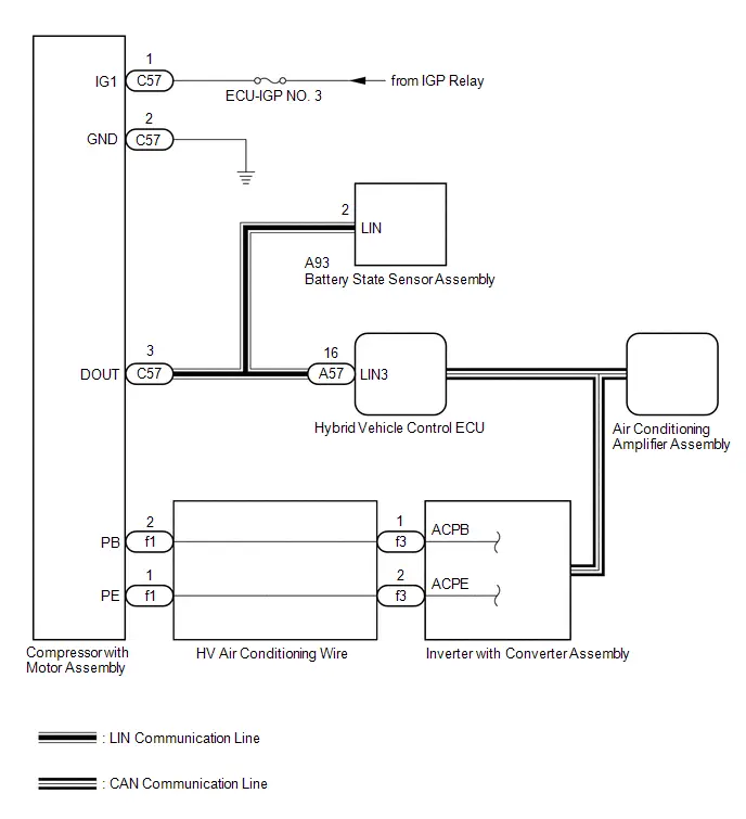
The hybrid vehicle control ECU and compressor with motor assembly communicate via a direct line. Compressor control is stopped and this DTC is stored if communication information is cut off or abnormal information occurs.
This DTC is also detected if high-voltage power supplied from the inverter with converter assembly to the compressor control circuit is shut off.
| DTC No. | Detection Item | DTC Detection Condition | Trouble Area | Memory | DTC Output from | Priority |
|---|---|---|---|---|---|---|
| B149887 | A/C Inverter Local Missing Message | Diagnosis Condition:
Malfunction:
Detection Time:
|
| Memorized | Air Conditioner | A |
| Toyota Prius Vehicle Condition | ||||
|---|---|---|---|---|
| Pattern 1 | Pattern 2 | Pattern 3 | ||
| Diagnosis Condition | Ignition switch ON (READY) | ○ | ○ | ○ |
| Malfunction | Error in communication line between the hybrid Toyota Prius vehicle control ECU and compressor with motor assembly | ○ | - | - |
| Open in communication line between the hybrid Toyota Prius vehicle control ECU and compressor with motor assembly | - | ○ | - | |
| High-voltage power source shut off | - | - | ○ | |
| Detection Time | - | - | - | |
| Trip Count | 1 trip | 1 trip | 1 trip | |
HINT:
If the conditions of either of these patterns are detected, a DTC will be stored.
WIRING DIAGRAM
for M20A-FXS: for 2ZR-FXE:
CAUTION / NOTICE / HINT
CAUTION:
-
Before inspecting the high-voltage system, take safety precautions such as wearing insulated gloves and removing the service plug grip to prevent electrical shocks. After removing the service plug grip, put it in your pocket to prevent other technicians from accidentally reconnecting it while you are working on the high-voltage system.
Click here


-
Do not touch the high-voltage connectors or terminals for 10 minutes after the service plug grip is removed.
for 2ZR-FXE: Click here

for M20A-FXS: Click here

NOTICE:
-
After turning the ignition switch off, waiting time may be required before disconnecting the cable from the negative (-) auxiliary battery terminal. Therefore, make sure to read the disconnecting the cable from the negative (-) auxiliary battery terminal notices before proceeding with work.
-
Before disconnecting battery:
Click here

-
Automatic learning chart:
Click here


-
Before disconnecting battery:
- Inspect the fuses for circuits related to this system before performing the following procedure.
-
The hybrid control system and air conditioning system output DTCs separately. Perform troubleshooting for the hybrid control system first if DTCs for both systems are output simultaneously.
for 2ZR-FXE: Click here

for M20A-FXS: Click here

-
The air conditioning system uses the CAN communication system. Inspect the communication functions by following How to Proceed with Troubleshooting. Troubleshoot the air conditioning system after confirming that the communication systems are functioning properly.
Click here

PROCEDURE
| 1. | CHECK FOR DTC (HYBRID CONTROL) |
(a) Check for DTCs.
Powertrain > Hybrid Control > Trouble Codes| Result | Proceed to |
|---|---|
| P058A01 and P162B87 are not output | A |
| P058A01 or P162B87 is output | B |
| B |

| GO TO STEP 7 |
|

| 2. | CHECK HARNESS AND CONNECTOR (COMPRESSOR WITH MOTOR ASSEMBLY - AUXILIARY BATTERY AND BODY GROUND) |
CAUTION:
Do not disconnect the connector on the high-voltage side.
NOTICE:
As other DTCs will be stored when the ignition switch is turned to ON with the connector disconnected, be sure to clear the DTCs after the inspection.
Pre-procedure1
(a) Disconnect the C57 compressor with motor assembly connector.
NOTICE:
Do not allow any foreign matter or water to enter the compressor with motor assembly.
Procedure1
| (b) Measure the voltage according to the value(s) in the table below. Standard Voltage:  Click Location & Routing(C57) Click Connector(C57) Click Location & Routing(C57) Click Connector(C57)
|
|
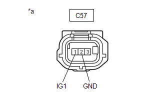
(c) Measure the resistance according to the value(s) in the table below.
Standard Resistance:
 Click Location & Routing(C57) Click Connector(C57)
 | Tester Connection | Condition | Specified Condition | Result |
|---|---|---|---|
| C57-2 (GND) - Body ground | Always | Below 1 Ω | Ω |
Post-procedure1
(d) None
| NG |

| REPAIR OR REPLACE HARNESS OR CONNECTOR |
|

| 3. | CHECK HARNESS AND CONNECTOR (COMPRESSOR WITH MOTOR ASSEMBLY - HYBRID Toyota Prius Vehicle CONTROL ECU) |
Pre-procedure1
(a) Disconnect the C57 compressor with motor assembly connector.
NOTICE:
Do not allow any foreign matter or water to enter the compressor with motor assembly.
(b) Disconnect the A57 hybrid vehicle control ECU connector.
Procedure1
(c) Measure the resistance according to the value(s) in the table below.
Standard Resistance:
 Click Location & Routing(C57,A57) Click Connector(C57) Click Connector(A57)
 | Tester Connection | Condition | Specified Condition | Result |
|---|---|---|---|
| C57-3 (DOUT) - A57-16 (LIN3) | Always | Below 1 Ω | Ω |
Post-procedure1
(d) None
| NG |

| REPAIR OR REPLACE HARNESS OR CONNECTOR |
|

| 4. | INSPECT HV AIR CONDITIONING WIRE |
CAUTION:
Be sure to wear insulated gloves.
Pre-procedure1
(a) Disconnect the f1 compressor with motor assembly connector.
NOTICE:
Do not allow any foreign matter or water to enter the compressor with motor assembly.
(b) Remove the HV air conditioning wire from the inverter with converter assembly.
NOTICE:
Make sure that no foreign matter, water, etc., enters the inverter with converter assembly.
HINT:
Click here

Procedure1
(c) Measure the resistance according to the value(s) in the table below.
Standard Resistance:
 Click Location & Routing(f1,f3) Click Connector(f1) Click Connector(f3)
 | Tester Connection | Condition | Specified Condition | Result |
|---|---|---|---|
| f1-2 (PB) - f3-1 (ACPB) | Always | Below 1 Ω | Ω |
Post-procedure1
(d) None
| NG |

| GO TO STEP 6 |
|

| 5. | INSPECT HV AIR CONDITIONING WIRE |
CAUTION:
Be sure to wear insulated gloves.
Pre-procedure1
(a) Disconnect the f1 compressor with motor assembly connector.
NOTICE:
Do not allow any foreign matter or water to enter the compressor with motor assembly.
(b) Remove the HV air conditioning wire from the inverter with converter assembly.
NOTICE:
Make sure that no foreign matter, water, etc., enters the inverter with converter assembly.
HINT:
Click here

Procedure1
(c) Measure the resistance according to the value(s) in the table below.
Standard Resistance:
 Click Location & Routing(f1,f3) Click Connector(f1) Click Connector(f3)
 | Tester Connection | Condition | Specified Condition | Result |
|---|---|---|---|
| f1-1 (PE) - f3-2 (ACPE) | Always | Below 1 Ω | Ω |
Post-procedure1
(d) None
| OK |

| REPLACE COMPRESSOR WITH MOTOR ASSEMBLY for 2ZR-FXE: Click here
for M20A-FXS: Click here
|


| NG |

| REPLACE HV AIR CONDITIONING WIRE |
| 6. | INSPECT HV AIR CONDITIONING WIRE |
CAUTION:
Be sure to wear insulated gloves.
Pre-procedure1
(a) Disconnect the f1 compressor with motor assembly connector.
NOTICE:
Do not allow any foreign matter or water to enter the compressor with motor assembly.
(b) Remove the HV air conditioning wire from the inverter with converter assembly.
NOTICE:
Make sure that no foreign matter, water, etc., enters the inverter with converter assembly.
HINT:
Click here

Procedure1
(c) Measure the resistance according to the value(s) in the table below.
Standard Resistance:
 Click Location & Routing(f1) Click Connector(f1)
 | Tester Connection | Condition | Specified Condition | Result |
|---|---|---|---|
| f1-2 (PB) - Other terminals and body ground | Always | 10 kΩ or higher | kΩ |
Post-procedure1
(d) None
| OK |

| REPLACE COMPRESSOR WITH MOTOR ASSEMBLY AND HV AIR CONDITIONING WIRE Compressor with motor assembly:
HV air conditioning wire:
|


| NG |

| REPLACE HV AIR CONDITIONING WIRE |
| 7. | CONFIRM MODEL |
| Result | Proceed to |
|---|---|
| for M20A-FXS | A |
| for 2ZR-FXE | B |
| B |

| GO TO STEP 11 |
|

| 8. | CHECK FOR DTC |
Pre-procedure1
(a) Disconnect the R29 battery state sensor assembly connector.
Procedure1
(b) Check for DTCs.
Body Electrical > Air Conditioner > Trouble Codes| Result | Proceed to |
|---|---|
| B149887 is not output | A |
| B149887 is output | B |
Post-procedure1
(c) None
| A |

| REPLACE BATTERY STATE SENSOR ASSEMBLY
|


|

| 9. | CHECK FOR DTC (HYBRID CONTROL) |
Pre-procedure1
(a) Connect the R29 battery state sensor assembly connector.
(b) Disconnect the C57 compressor with motor assembly connector.
NOTICE:
Do not allow any foreign matter or water to enter the compressor with motor assembly.
Procedure1
(c) Check for DTCs.
Powertrain > Hybrid Control > Trouble Codes| Result | Proceed to |
|---|---|
| P058A01 and P162B87 are not output | A |
| P058A01 or P162B87 is output | B |
Post-procedure1
(d) None
| A |

| REPLACE COMPRESSOR WITH MOTOR ASSEMBLY
|


|

| 10. | CHECK HARNESS AND CONNECTOR (COMPRESSOR WITH MOTOR ASSEMBLY - HYBRID Toyota Prius Vehicle CONTROL ECU) |
Pre-procedure1
(a) Disconnect the R29 battery state sensor assembly connector.
(b) Disconnect the C57 compressor with motor assembly connector.
NOTICE:
Do not allow any foreign matter or water to enter the compressor with motor assembly.
(c) Disconnect the A57 hybrid Toyota Prius vehicle control ECU connector.
Procedure1
(d) Measure the resistance according to the value(s) in the table below.
Standard Resistance:
 Click Location & Routing(A57,C57,R29) Click Connector(A57) Click Connector(C57) Click Connector(R29)
 | Tester Connection | Condition | Specified Condition | Result |
|---|---|---|---|
| A57-16 (LIN3) - C57-3 (DOUT) | Always | Below 1 Ω | Ω |
| A57-16 (LIN3) - R29-2 (LIN) | Always | Below 1 Ω | Ω |
| A57-16 (LIN3) - Other terminals and body ground | Always | 10 kΩ or higher | kΩ |
| C57-3 (DOUT) - Other terminals and body ground | Always | 10 kΩ or higher | kΩ |
| R29-2 (LIN) - Other terminals and body ground | Always | 10 kΩ or higher | kΩ |
Post-procedure1
(e) None
| OK |

| REPLACE HYBRID Toyota Prius Vehicle CONTROL ECU
|


| NG |

| REPAIR OR REPLACE HARNESS OR CONNECTOR |
| 11. | CHECK FOR DTC |
Pre-procedure1
(a) Disconnect the A93 battery state sensor assembly connector.
Procedure1
(b) Check for DTCs.
Body Electrical > Air Conditioner > Trouble Codes| Result | Proceed to |
|---|---|
| B149887 is not output | A |
| B149887 is output | B |
Post-procedure1
(c) None
| A |

| REPLACE BATTERY STATE SENSOR ASSEMBLY |
|

| 12. | CHECK FOR DTC (HYBRID CONTROL) |
Pre-procedure1
(a) Connect the A93 battery state sensor assembly connector.
(b) Disconnect the C57 compressor with motor assembly connector.
NOTICE:
Do not allow any foreign matter or water to enter the compressor with motor assembly.
Procedure1
(c) Check for DTCs.
Powertrain > Hybrid Control > Trouble Codes| Result | Proceed to |
|---|---|
| P058A01 and P162B87 are not output | A |
| P058A01 or P162B87 is output | B |
Post-procedure1
(d) None
| A |

| REPLACE COMPRESSOR WITH MOTOR ASSEMBLY
|


|

| 13. | CHECK HARNESS AND CONNECTOR (COMPRESSOR WITH MOTOR ASSEMBLY - HYBRID Toyota Prius Vehicle CONTROL ECU) |
Pre-procedure1
(a) Disconnect the A93 battery state sensor assembly connector.
(b) Disconnect the C57 compressor with motor assembly connector.
NOTICE:
Do not allow any foreign matter or water to enter the compressor with motor assembly.
(c) Disconnect the A57 hybrid Toyota Prius vehicle control ECU connector.
Procedure1
(d) Measure the resistance according to the value(s) in the table below.
Standard Resistance:
 Click Location & Routing(A57,C57,A93) Click Connector(A57) Click Connector(C57) Click Connector(A93)
 | Tester Connection | Condition | Specified Condition | Result |
|---|---|---|---|
| A57-16 (LIN3) - C57-3 (DOUT) | Always | Below 1 Ω | Ω |
| A57-16 (LIN3) - A93-2 (LIN) | Always | Below 1 Ω | Ω |
| A57-16 (LIN3) - Other terminals and body ground | Always | 10 kΩ or higher | kΩ |
| C57-3 (DOUT) - Other terminals and body ground | Always | 10 kΩ or higher | kΩ |
| A93-2 (LIN) - Other terminals and body ground | Always | 10 kΩ or higher | kΩ |
Post-procedure1
(e) None
| OK |

| REPLACE HYBRID Toyota Prius Vehicle CONTROL ECU
|


| NG |

| REPAIR OR REPLACE HARNESS OR CONNECTOR |
Lost Communication with Front Panel LIN Missing Message (B14B287)
DESCRIPTION
The air conditioning control assembly communicates with the air conditioning amplifier assembly via LIN communication.
| DTC No. | Detection Item | DTC Detection Condition | Trouble Area | Memory | DTC Output from | Priority |
|---|---|---|---|---|---|---|
| B14B287 | Lost Communication with Front Panel LIN Missing Message | Diagnosis Condition:
Malfunction:
Detection Time:
|
| Memorized | Air Conditioner | A |
| Toyota Prius Vehicle Condition | |||
|---|---|---|---|
| Pattern 1 | Pattern 2 | ||
| Diagnosis Condition | Ignition switch ON | ○ | ○ |
| Malfunction | Error in communication line between air conditioning amplifier assembly and air conditioning control assembly | ○ | - |
| Open in communication line between air conditioning amplifier assembly and air conditioning control assembly | - | ○ | |
| Detection Time | Continuously for 10 seconds or more | Continuously for 10 seconds or more | |
| Trip Count | 1 trip | 1 trip | |
HINT:
If the conditions of either of these patterns are detected, a DTC will be stored.
WIRING DIAGRAM
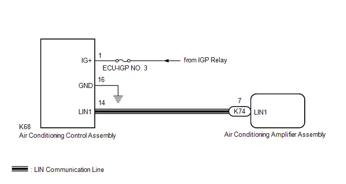
CAUTION / NOTICE / HINT
NOTICE:
Inspect the fuses for circuits related to this system before performing the following procedure.
PROCEDURE
| 1. | CHECK HARNESS AND CONNECTOR (AIR CONDITIONING CONTROL ASSEMBLY - AUXILIARY BATTERY) |
Pre-procedure1
(a) Disconnect the K68 air conditioning control assembly connector.
Procedure1
(b) Measure the voltage according to the value(s) in the table below.
Standard Voltage:
 Click Location & Routing(K68) Click Connector(K68)
 | Tester Connection | Condition | Specified Condition | Result |
|---|---|---|---|
| K68-1 (IG ) - Body ground | Ignition switch ON | 11 to 14 V | V |
Post-procedure1
(c) None
| NG |

| REPAIR OR REPLACE HARNESS OR CONNECTOR |
|

| 2. | CHECK HARNESS AND CONNECTOR (AIR CONDITIONING CONTROL ASSEMBLY - BODY GROUND) |
Pre-procedure1
(a) Disconnect the K68 air conditioning control assembly connector.
Procedure1
(b) Measure the resistance according to the value(s) in the table below.
Standard Resistance:
 Click Location & Routing(K68) Click Connector(K68)
 | Tester Connection | Condition | Specified Condition | Result |
|---|---|---|---|
| K68-16 (GND) - Body ground | Always | Below 1 Ω | Ω |
Post-procedure1
(c) None
| NG |

| REPAIR OR REPLACE HARNESS OR CONNECTOR |
|

| 3. | CHECK HARNESS AND CONNECTOR (AIR CONDITIONING AMPLIFIER ASSEMBLY - AIR CONDITIONING CONTROL ASSEMBLY) |
Pre-procedure1
(a) Disconnect the K68 air conditioning control assembly connector.
(b) Disconnect the K74 air conditioning amplifier assembly connector.
Procedure1
(c) Measure the resistance according to the value(s) in the table below.
Standard Resistance:
 Click Location & Routing(K68,K74) Click Connector(K68) Click Connector(K74)
 | Tester Connection | Condition | Specified Condition | Result |
|---|---|---|---|
| K68-14 (LIN1) - K74-7 (LIN1) | Always | Below 1 Ω | Ω |
| K68-14 (LIN1) or K74-7 (LIN1) - Other terminals and body ground | Always | 10 kΩ or higher | kΩ |
Post-procedure1
(d) None
| NG |

| REPAIR OR REPLACE HARNESS OR CONNECTOR |
|

| 4. | CHECK AIR CONDITIONING AMPLIFIER ASSEMBLY (OUTPUT) |
Pre-procedure1
(a) Disconnect the K68 air conditioning control assembly connector.
(b) Connect the K74 air conditioning amplifier assembly connector.
Procedure1
| (c) Using an oscilloscope, check the waveform.
OK: The waveform displays properly. Result:
|
|

Post-procedure1
(d) None
| NG |

| REPLACE AIR CONDITIONING AMPLIFIER ASSEMBLY
|


|

| 5. | CHECK AIR CONDITIONING CONTROL ASSEMBLY (OUTPUT) |
Pre-procedure1
(a) Connect the K68 air conditioning control assembly connector.
Procedure1
| (b) Using an oscilloscope, check the waveform.
OK: The waveform displays properly. Result:
|
|
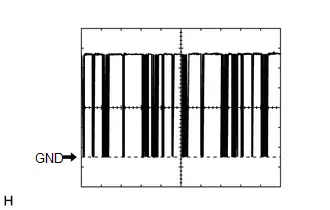
Post-procedure1
(c) None
| OK |

| REPLACE AIR CONDITIONING AMPLIFIER ASSEMBLY
|


| NG |

| REPLACE AIR CONDITIONING CONTROL ASSEMBLY |
Front Left Solar Sensor Circuit Short to Battery or Open (B14D215)
DESCRIPTION
The solar sensor (cooler thermistor) is installed on the upper side of the instrument panel. It detects sunlight to control air conditioning control in AUTO mode.
The output voltage from the solar sensor (cooler thermistor) varies in accordance with the amount of sunlight. When the sunlight increases, the output voltage increases. As the sunlight decreases, the output voltage decreases.
The air conditioning amplifier assembly detects changes in the output voltage from the solar sensor (cooler thermistor).
| DTC No. | Detection Item | DTC Detection Condition | Trouble Area | Memory | DTC Output from | Priority |
|---|---|---|---|---|---|---|
| B14D215 | Front Left Solar Sensor Circuit Short to Battery or Open | Diagnosis Condition:
Malfunction:
Detection Time:
|
| Memorized | Air Conditioner | A |
WIRING DIAGRAM

PROCEDURE
| 1. | READ VALUE USING GTS |
(a) Read the Data List according to the display on the GTS.
Body Electrical > Air Conditioner > Data List| Tester Display | Measurement Item | Range | Normal Condition | Diagnostic Note |
|---|---|---|---|---|
| Front Left Solar Sensor | Front left side solar sensor (cooler thermistor) | 0 to 6553.5 W/m^2 | Front left side solar sensor (cooler thermistor) value increases as brightness increases | Solar sensor (cooler thermistor) circuit malfunction |
| Tester Display |
|---|
| Front Left Solar Sensor |
OK:
The display is as specified in the normal condition column.
| OK |

| REPLACE AIR CONDITIONING AMPLIFIER ASSEMBLY
|


|

| 2. | INSPECT SOLAR SENSOR (COOLER THERMISTOR) |
Click here

| NG |

| REPLACE SOLAR SENSOR (COOLER THERMISTOR)
|


|

| 3. | CHECK HARNESS AND CONNECTOR (AIR CONDITIONING AMPLIFIER ASSEMBLY - SOLAR SENSOR (COOLER THERMISTOR)) |
Pre-procedure1
(a) Disconnect the G2 solar sensor (cooler thermistor) connector.
(b) Disconnect the K73 air conditioning amplifier assembly connector.
Procedure1
(c) Measure the resistance according to the value(s) in the table below.
Standard Resistance:
 Click Location & Routing(G2,K73) Click Connector(G2) Click Connector(K73)
 | Tester Connection | Condition | Specified Condition | Result |
|---|---|---|---|
| G2-1 (SS ) - K73-2 (S5-1) | Always | Below 1 Ω | Ω |
| G2-2 (SS-) - K73-9 (TS) | Always | Below 1 Ω | Ω |
| G2-1 (SS ) or K73-2 (S5-1) - Other terminals and body ground | Always | 10 kΩ or higher | kΩ |
| G2-2 (SS-) or K73-9 (TS) - Other terminals and body ground | Always | 10 kΩ or higher | kΩ |
(d) Measure the voltage according to the value(s) in the table below.
Standard Voltage:
 Click Location & Routing(K73) Click Connector(K73)
 | Tester Connection | Condition | Specified Condition | Result |
|---|---|---|---|
| K73-2 (S5-1) - Body ground | Ignition switch ON | Below 1 V | V |
| K73-9 (TS) - Body ground | Ignition switch ON | Below 1 V | V |
Post-procedure1
(e) None
| OK |

| REPLACE AIR CONDITIONING AMPLIFIER ASSEMBLY
|


| NG |

| REPAIR OR REPLACE HARNESS OR CONNECTOR |
Ambient Temperature Sensor Circuit Short to Ground (P007011)
DESCRIPTION
The ambient temp. sensor (thermistor assembly) is installed in front of the cooler condenser assembly to detect the ambient temperature, which is used to control the air conditioning system. This sensor is connected to the air conditioning amplifier assembly and detects fluctuations in the ambient temperature. This data is used for controlling the cabin temperature. The sensor sends a signal to the air conditioning amplifier assembly. The resistance of the ambient temp. sensor (thermistor assembly) changes in accordance with the ambient temperature. As the temperature decreases, the resistance increases. As the temperature increases, the resistance decreases.
The air conditioning amplifier assembly applies voltage (5 V) to the ambient temp. sensor (thermistor assembly) and reads voltage changes due to changes in the resistance of the ambient temp. sensor (thermistor assembly).
| DTC No. | Detection Item | DTC Detection Condition | Trouble Area | Memory | DTC Output from | Priority |
|---|---|---|---|---|---|---|
| P007011 | Ambient Temperature Sensor Circuit Short to Ground | Diagnosis Condition:
Malfunction:
Detection Time:
|
| Memorized | Air Conditioner | A |
WIRING DIAGRAM
w/o Grille Shutter System: w/ Grille Shutter System:

PROCEDURE
| 1. | READ VALUE USING GTS (AMBIENT TEMPERATURE SENSOR) |
(a) Read the Data List according to the display on the GTS.
Body Electrical > Air Conditioner > Data List| Tester Display | Measurement Item | Range | Normal Condition | Diagnostic Note |
|---|---|---|---|---|
| Ambient Temperature Sensor | Ambient temp. sensor (thermistor assembly) | -327.68 to 327.67°C | Actual ambient temperature displayed | Ambient temp. sensor (thermistor assembly) circuit malfunction |
| Tester Display |
|---|
| Ambient Temperature Sensor |
OK:
The display is as specified in the normal condition column.
| OK |

| REPLACE AIR CONDITIONING AMPLIFIER ASSEMBLY
|


|

| 2. | INSPECT AMBIENT TEMP. SENSOR (THERMISTOR ASSEMBLY) |
Click here

| NG |

| REPLACE AMBIENT TEMP. SENSOR (THERMISTOR ASSEMBLY) |
|

| 3. | CONFIRM MODEL |
| Result | Proceed to |
|---|---|
| w/o Grille Shutter System | A |
| w/ Grille Shutter System | B |
| B |

| GO TO STEP 5 |
|

| 4. | CHECK HARNESS AND CONNECTOR (AMBIENT TEMP. SENSOR (THERMISTOR ASSEMBLY) - AIR CONDITIONING AMPLIFIER ASSEMBLY) |
Pre-procedure1
(a) Disconnect the A23 ambient temp. sensor (thermistor assembly) connector.
(b) Disconnect the K73 air conditioning amplifier assembly connector.
Procedure1
(c) Measure the resistance according to the value(s) in the table below.
Standard Resistance:
 Click Location & Routing(A23,K73) Click Connector(A23) Click Connector(K73)
 | Tester Connection | Condition | Specified Condition | Result |
|---|---|---|---|
| A23-1 ( ) or K73-1 (TAM) - Other terminals and body ground | Always | 10 kΩ or higher | kΩ |
| A23-2 (-) or K73-14 (SG-2) - Other terminals and body ground | Always | 10 kΩ or higher | kΩ |
Post-procedure1
(d) None
| OK |

| REPLACE AIR CONDITIONING AMPLIFIER ASSEMBLY
|


| NG |

| REPAIR OR REPLACE HARNESS OR CONNECTOR |
| 5. | CHECK HARNESS AND CONNECTOR (AMBIENT TEMP. SENSOR (THERMISTOR ASSEMBLY) - AIR CONDITIONING AMPLIFIER ASSEMBLY) |
Pre-procedure1
(a) Disconnect the A28 ambient temp. sensor (thermistor assembly) connector.
(b) Disconnect the K73 air conditioning amplifier assembly connector.
Procedure1
(c) Measure the resistance according to the value(s) in the table below.
Standard Resistance:
 Click Location & Routing(A28,K73) Click Connector(A28) Click Connector(K73)
 | Tester Connection | Condition | Specified Condition | Result |
|---|---|---|---|
| A28-1 ( ) or K73-1 (TAM) - Other terminals and body ground | Always | 10 kΩ or higher | kΩ |
| A28-2 (-) or K73-14 (SG-2) - Other terminals and body ground | Always | 10 kΩ or higher | kΩ |
Post-procedure1
(d) None
| OK |

| REPLACE AIR CONDITIONING AMPLIFIER ASSEMBLY
|


| NG |

| REPAIR OR REPLACE HARNESS OR CONNECTOR |
Ambient Temperature Sensor Circuit Short to Battery or Open (P007015)
DESCRIPTION
The ambient temp. sensor (thermistor assembly) is installed in front of the cooler condenser assembly to detect the ambient temperature, which is used to control the air conditioning system. This sensor is connected to the air conditioning amplifier assembly and detects fluctuations in the ambient temperature. This data is used for controlling the cabin temperature. The sensor sends a signal to the air conditioning amplifier assembly. The resistance of the ambient temp. sensor (thermistor assembly) changes in accordance with the ambient temperature. As the temperature decreases, the resistance increases. As the temperature increases, the resistance decreases.
The air conditioning amplifier assembly applies voltage (5 V) to the ambient temp. sensor (thermistor assembly) and reads voltage changes due to changes in the resistance of the ambient temp. sensor (thermistor assembly).
| DTC No. | Detection Item | DTC Detection Condition | Trouble Area | Memory | DTC Output from | Priority |
|---|---|---|---|---|---|---|
| P007015 | Ambient Temperature Sensor Circuit Short to Battery or Open | Diagnosis Condition:
Malfunction:
Detection Time:
|
| Memorized | Air Conditioner | A |
| Toyota Prius Vehicle Condition | |||
|---|---|---|---|
| Pattern 1 | Pattern 2 | ||
| Diagnosis Condition | Ignition switch ON | ○ | ○ |
| Malfunction | Open in ambient temperature sensor circuit | ○ | - |
| Short ( B) in ambient temperature sensor circuit | - | ○ | |
| Detection Time | Continuously for 4 seconds or more | Continuously for 4 seconds or more | |
| Trip Count | 1 trip | 1 trip | |
HINT:
If the conditions of either of these patterns are detected, a DTC will be stored.
WIRING DIAGRAM
w/o Grille Shutter System: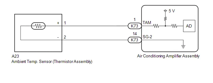 w/ Grille Shutter System:

PROCEDURE
| 1. | READ VALUE USING GTS (AMBIENT TEMPERATURE SENSOR) |
(a) Read the Data List according to the display on the GTS.
Body Electrical > Air Conditioner > Data List| Tester Display | Measurement Item | Range | Normal Condition | Diagnostic Note |
|---|---|---|---|---|
| Ambient Temperature Sensor | Ambient temp. sensor (thermistor assembly) | -327.68 to 327.67°C | Actual ambient temperature displayed | Ambient temp. sensor (thermistor assembly) circuit malfunction |
| Tester Display |
|---|
| Ambient Temperature Sensor |
OK:
The display is as specified in the normal condition column.
| OK |

| REPLACE AIR CONDITIONING AMPLIFIER ASSEMBLY
|


|

| 2. | INSPECT AMBIENT TEMP. SENSOR (THERMISTOR ASSEMBLY) |
Click here

| NG |

| REPLACE AMBIENT TEMP. SENSOR (THERMISTOR ASSEMBLY) |
|

| 3. | CONFIRM MODEL |
| Result | Proceed to |
|---|---|
| w/o Grille Shutter System | A |
| w/ Grille Shutter System | B |
| B |

| GO TO STEP 5 |
|

| 4. | CHECK HARNESS AND CONNECTOR (AIR CONDITIONING AMPLIFIER ASSEMBLY - AMBIENT TEMP. SENSOR (THERMISTOR ASSEMBLY)) |
Pre-procedure1
(a) Disconnect the A23 ambient temp. sensor (thermistor assembly) connector.
(b) Disconnect the K73 air conditioning amplifier assembly connector.
Procedure1
(c) Measure the resistance according to the value(s) in the table below.
Standard Resistance:
 Click Location & Routing(A23,K73) Click Connector(A23) Click Connector(K73)
 | Tester Connection | Condition | Specified Condition | Result |
|---|---|---|---|
| A23-1 ( ) - K73-1 (TAM) | Always | Below 1 Ω | Ω |
| A23-2 (-) - K73-14 (SG-2) | Always | Below 1 Ω | Ω |
(d) Measure the voltage according to the value(s) in the table below.
Standard Voltage:
 Click Location & Routing(K73) Click Connector(K73)
 | Tester Connection | Condition | Specified Condition | Result |
|---|---|---|---|
| K73-1 (TAM) - Body ground | Ignition switch ON | Below 1 V | V |
| K73-14 (SG-2) - Body ground | Ignition switch ON | Below 1 V | V |
Post-procedure1
(e) None
| OK |

| REPLACE AIR CONDITIONING AMPLIFIER ASSEMBLY
|


| NG |

| REPAIR OR REPLACE HARNESS OR CONNECTOR |
| 5. | CHECK HARNESS AND CONNECTOR (AIR CONDITIONING AMPLIFIER ASSEMBLY - AMBIENT TEMP. SENSOR (THERMISTOR ASSEMBLY)) |
Pre-procedure1
(a) Disconnect the A28 ambient temp. sensor (thermistor assembly) connector.
(b) Disconnect the K73 air conditioning amplifier assembly connector.
Procedure1
(c) Measure the resistance according to the value(s) in the table below.
Standard Resistance:
 Click Location & Routing(A28,K73) Click Connector(A28) Click Connector(K73)
 | Tester Connection | Condition | Specified Condition | Result |
|---|---|---|---|
| A28-1 ( ) - K73-1 (TAM) | Always | Below 1 Ω | Ω |
| A28-2 (-) - K73-14 (SG-2) | Always | Below 1 Ω | Ω |
(d) Measure the voltage according to the value(s) in the table below.
Standard Voltage:
 Click Location & Routing(K73) Click Connector(K73)
 | Tester Connection | Condition | Specified Condition | Result |
|---|---|---|---|
| K73-1 (TAM) - Body ground | Ignition switch ON | Below 1 V | V |
| K73-14 (SG-2) - Body ground | Ignition switch ON | Below 1 V | V |
Post-procedure1
(e) None
| OK |

| REPLACE AIR CONDITIONING AMPLIFIER ASSEMBLY
|


| NG |

| REPAIR OR REPLACE HARNESS OR CONNECTOR |
Refrigerant Pressure Sensor Circuit Short to Ground (P053011)
DESCRIPTION
The air conditioning pressure sensor, which is installed to the high pressure side pipe to detect refrigerant pressure, sends a refrigerant pressure signal to the air conditioning amplifier assembly. The air conditioning amplifier assembly converts this signal to a pressure value according to the sensor characteristics and uses it to control the compressor.
This DTC is stored if refrigerant pressure on the high pressure side is extremely low.
| DTC No. | Detection Item | DTC Detection Condition | Trouble Area | Memory | DTC Output from | Priority |
|---|---|---|---|---|---|---|
| P053011 | Refrigerant Pressure Sensor Circuit Short to Ground | Diagnosis Condition:
Malfunction:
Detection Time:
|
| Memorized | Air Conditioner | A |
WIRING DIAGRAM
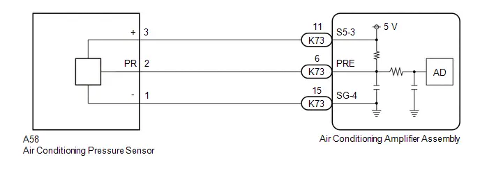
PROCEDURE
| 1. | CHECK COMPARE REFRIGERANT GAS PRESSURE VALUES SHOWN ON GTS AND MANIFOLD GAUGE SET |
Pre-procedure1
(a) Install a manifold gauge set.
HINT:
for HFC-134a(R134a): Click here

for HFO-1234yf(R1234yf): Click here

Procedure1
(b) Compare the values displayed in the Data List and on the manifold gauge.
Body Electrical > Air Conditioner > Data List| Tester Display | Measurement Item | Range | Normal Condition | Diagnostic Note |
|---|---|---|---|---|
| Regulator Pressure Sensor | Air conditioning pressure sensor | -32.768 to 32.767 MPaG | Actual refrigerant pressure displayed |
|
| Tester Display |
|---|
| Regulator Pressure Sensor |
| Result | Proceed to |
|---|---|
| Data List value and manifold gauge set value do not match | A |
| Data List value matches manifold gauge set value | B |
Post-procedure1
(c) None
| B |

| INSPECT REFRIGERANT PRESSURE WITH MANIFOLD GAUGE SET for HFC-134a(R134a): Click here
for HFO-1234yf(R1234yf): Click here
|


|

| 2. | READ VALUE USING GTS (REGULATOR PRESSURE SENSOR) |
(a) Read the Data List according to the display on the GTS.
Body Electrical > Air Conditioner > Data List| Tester Display | Measurement Item | Range | Normal Condition | Diagnostic Note |
|---|---|---|---|---|
| Regulator Pressure Sensor | Air conditioning pressure sensor | -32.768 to 32.767 MPaG | Actual refrigerant pressure displayed |
|
| Tester Display |
|---|
| Regulator Pressure Sensor |
OK:
Disconnecting the A58 connector of the air conditioning pressure sensor causes the Data List value to change.
| Result | Proceed to |
|---|---|
| Regulator pressure sensor value changes | A |
| Regulator pressure sensor value does not change | B |
| B |

| GO TO STEP 5 |
|

| 3. | CHECK HARNESS AND CONNECTOR (AIR CONDITIONING PRESSURE SENSOR - POWER SOURCE) |
Pre-procedure1
(a) Disconnect the A58 air conditioning pressure sensor connector.
Procedure1
| (b) Measure the voltage according to the value(s) in the table below. Standard Voltage:  Click Location & Routing(A58) Click Connector(A58) Click Location & Routing(A58) Click Connector(A58)
Result:
|
|

Post-procedure1
(c) None
| OK |

| REPLACE AIR CONDITIONING PRESSURE SENSOR
|


|

| 4. | CHECK HARNESS AND CONNECTOR (AIR CONDITIONING AMPLIFIER ASSEMBLY - AIR CONDITIONING PRESSURE SENSOR) |
Pre-procedure1
(a) Disconnect the A58 air conditioning pressure sensor connector.
(b) Disconnect the K73 air conditioning amplifier assembly connector.
Procedure1
(c) Measure the resistance according to the value(s) in the table below.
Standard Resistance:
 Click Location & Routing(A58,K73) Click Connector(A58) Click Connector(K73)
 | Tester Connection | Condition | Specified Condition | Result |
|---|---|---|---|
| A58-3 ( ) - K73-11 (S5-3) | Always | Below 1 Ω | Ω |
Post-procedure1
(d) None
| OK |

| REPLACE AIR CONDITIONING AMPLIFIER ASSEMBLY
|


| NG |

| REPAIR OR REPLACE HARNESS OR CONNECTOR |
| 5. | CHECK HARNESS AND CONNECTOR (AIR CONDITIONING PRESSURE SENSOR - BODY GROUND) |
Pre-procedure1
(a) Disconnect the A58 air conditioning pressure sensor connector.
Procedure1
| (b) Measure the voltage according to the value(s) in the table below. Standard Voltage:  Click Location & Routing(A58) Click Connector(A58) Click Location & Routing(A58) Click Connector(A58)
Result:
|
|

Post-procedure1
(c) None
| OK |

| REPLACE AIR CONDITIONING AMPLIFIER ASSEMBLY
|


|

| 6. | CHECK HARNESS AND CONNECTOR (AIR CONDITIONING PRESSURE SENSOR - AIR CONDITIONING AMPLIFIER ASSEMBLY) |
Pre-procedure1
(a) Disconnect the A58 air conditioning pressure sensor connector.
(b) Disconnect the K73 air conditioning amplifier assembly connector.
Procedure1
(c) Measure the resistance according to the value(s) in the table below.
Standard Resistance:
 Click Location & Routing(A58,K73) Click Connector(A58) Click Connector(K73)
 | Tester Connection | Condition | Specified Condition | Result |
|---|---|---|---|
| A58-2 (PR) or K73-6 (PRE) - Other terminals and body ground | Always | 10 kΩ or higher | kΩ |
Post-procedure1
(d) None
| OK |

| REPLACE AIR CONDITIONING AMPLIFIER ASSEMBLY
|


| NG |

| REPAIR OR REPLACE HARNESS OR CONNECTOR |
Refrigerant Pressure Sensor Circuit Short to Battery or Open (P053015)
DESCRIPTION
The air conditioning pressure sensor, which is installed to the high pressure side pipe to detect refrigerant pressure, sends a refrigerant pressure signal to the air conditioning amplifier assembly. The air conditioning amplifier assembly converts this signal to a pressure value according to the sensor characteristics and uses it to control the compressor.
| DTC No. | Detection Item | DTC Detection Condition | Trouble Area | Memory | DTC Output from | Priority |
|---|---|---|---|---|---|---|
| P053015 | Refrigerant Pressure Sensor Circuit Short to Battery or Open | Diagnosis Condition:
Malfunction:
Detection Time:
|
| Memorized | Air Conditioner | A |
| Toyota Prius Vehicle Condition | |||
|---|---|---|---|
| Pattern 1 | Pattern 2 | ||
| Diagnosis Condition | Ignition switch ON | ○ | ○ |
| Malfunction | Open in air conditioning pressure sensor circuit | ○ | - |
| Short ( B) in air conditioning pressure sensor circuit | - | ○ | |
| Detection Time | Continuously for 4 seconds or more | Continuously for 4 seconds or more | |
| Trip Count | 1 trip | 1 trip | |
HINT:
If the conditions of either of these patterns are detected, a DTC will be stored.
WIRING DIAGRAM

CAUTION / NOTICE / HINT
NOTICE:
If DTC P05347A is output at the same time, perform troubleshooting for DTC P05347A first.
Click here

HINT:
If a connector is disconnected or not installed correctly, securely connect it and check for DTCs.
PROCEDURE
| 1. | CHECK COMPARE REFRIGERANT GAS PRESSURE VALUES SHOWN ON GTS AND MANIFOLD GAUGE SET |
Pre-procedure1
(a) Install a manifold gauge set.
HINT:
for HFC-134a(R134a): Click here

for HFO-1234yf(R1234yf): Click here

Procedure1
(b) Compare the values displayed in the Data List and on the manifold gauge.
Body Electrical > Air Conditioner > Data List| Tester Display | Measurement Item | Range | Normal Condition | Diagnostic Note |
|---|---|---|---|---|
| Regulator Pressure Sensor | Air conditioning pressure sensor | -32.768 to 32.767 MPaG | Actual refrigerant pressure displayed |
|
| Tester Display |
|---|
| Regulator Pressure Sensor |
| Result | Proceed to |
|---|---|
| Data List value and manifold gauge set value do not match | A |
| Data List value matches manifold gauge set value | B |
Post-procedure1
(c) None
| B |

| INSPECT REFRIGERANT PRESSURE WITH MANIFOLD GAUGE SET for HFC-134a(R134a): Click here
for HFO-1234yf(R1234yf): Click here
|


|

| 2. | CHECK HARNESS AND CONNECTOR (AIR CONDITIONING PRESSURE SENSOR - BODY GROUND) |
Pre-procedure1
(a) Disconnect the A58 air conditioning pressure sensor connector.
Procedure1
| (b) Measure the resistance according to the value(s) in the table below. Standard Resistance:  Click Location & Routing(A58) Click Connector(A58) Click Location & Routing(A58) Click Connector(A58)
Result:
|
|

Post-procedure1
(c) None
| NG |

| GO TO STEP 8 |
|

| 3. | CHECK HARNESS AND CONNECTOR (AIR CONDITIONING PRESSURE SENSOR - BODY GROUND) |
Pre-procedure1
(a) Disconnect the A58 air conditioning pressure sensor connector.
Procedure1
| (b) Measure the voltage according to the value(s) in the table below. Standard Voltage:  Click Location & Routing(A58) Click Connector(A58) Click Location & Routing(A58) Click Connector(A58)
Result:
|
|

Post-procedure1
(c) None
| B |

| GO TO STEP 5 |
| C |

| GO TO STEP 7 |
|

| 4. | CHECK HARNESS AND CONNECTOR (AIR CONDITIONING AMPLIFIER ASSEMBLY - AIR CONDITIONING PRESSURE SENSOR) |
Pre-procedure1
(a) Disconnect the A58 air conditioning pressure sensor connector.
(b) Disconnect the K73 air conditioning amplifier assembly connector.
Procedure1
(c) Measure the resistance according to the value(s) in the table below.
Standard Resistance:
 Click Location & Routing(A58,K73) Click Connector(A58) Click Connector(K73)
 | Tester Connection | Condition | Specified Condition | Result |
|---|---|---|---|
| A58-2 (PR) or K73-6 (PRE) - Other terminals and body ground | Always | 10 kΩ or higher | kΩ |
Post-procedure1
(d) None
| OK |

| REPLACE AIR CONDITIONING AMPLIFIER ASSEMBLY
|


| NG |

| REPAIR OR REPLACE HARNESS OR CONNECTOR |
| 5. | CHECK AIR CONDITIONING AMPLIFIER ASSEMBLY (INTERNAL CIRCUIT RESISTANCE) |
Pre-procedure1
(a) Disconnect the A58 air conditioning pressure sensor connector.
Procedure1
| (b) Measure the resistance according to the value(s) in the table below. Standard Resistance:  Click Location & Routing(A58) Click Connector(A58) Click Location & Routing(A58) Click Connector(A58)
HINT: After turning the ignition switch off, wait at least 30 seconds before performing the measurement. Result:
|
|
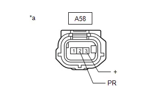
Post-procedure1
(c) None
| OK |

| REPLACE AIR CONDITIONING PRESSURE SENSOR
|


|

| 6. | CHECK HARNESS AND CONNECTOR (AIR CONDITIONING PRESSURE SENSOR - AIR CONDITIONING AMPLIFIER ASSEMBLY) |
Pre-procedure1
(a) Disconnect the A58 air conditioning pressure sensor connector.
(b) Disconnect the K73 air conditioning amplifier assembly connector.
Procedure1
(c) Measure the resistance according to the value(s) in the table below.
Standard Resistance:
 Click Location & Routing(A58,K73) Click Connector(A58) Click Connector(K73)
 | Tester Connection | Condition | Specified Condition | Result |
|---|---|---|---|
| A58-2 (PR) - A58-3 ( ) | Always | 10 kΩ or higher | kΩ |
| K73-6 (PRE) - K73-11 (S5-3) | Always | 10 kΩ or higher | kΩ |
Post-procedure1
(d) None
| OK |

| REPLACE AIR CONDITIONING AMPLIFIER ASSEMBLY
|


| NG |

| REPAIR OR REPLACE HARNESS OR CONNECTOR |
| 7. | CHECK HARNESS AND CONNECTOR (AIR CONDITIONING AMPLIFIER ASSEMBLY - AIR CONDITIONING PRESSURE SENSOR) |
Pre-procedure1
(a) Disconnect the A58 air conditioning pressure sensor connector.
(b) Disconnect the K73 air conditioning amplifier assembly connector.
Procedure1
(c) Measure the resistance according to the value(s) in the table below.
Standard Resistance:
 Click Location & Routing(A58,K73) Click Connector(A58) Click Connector(K73)
 | Tester Connection | Condition | Specified Condition | Result |
|---|---|---|---|
| A58-2 (PR) - K73-6 (PRE) | Always | Below 1 Ω | Ω |
Post-procedure1
(d) None
| OK |

| REPLACE AIR CONDITIONING AMPLIFIER ASSEMBLY
|


| NG |

| REPAIR OR REPLACE HARNESS OR CONNECTOR |
| 8. | CHECK HARNESS AND CONNECTOR (AIR CONDITIONING AMPLIFIER ASSEMBLY - AIR CONDITIONING PRESSURE SENSOR) |
Pre-procedure1
(a) Disconnect the A58 air conditioning pressure sensor connector.
(b) Disconnect the K73 air conditioning amplifier assembly connector.
Procedure1
(c) Measure the resistance according to the value(s) in the table below.
Standard Resistance:
 Click Location & Routing(A58,K73) Click Connector(A58) Click Connector(K73)
 | Tester Connection | Condition | Specified Condition | Result |
|---|---|---|---|
| A58-1 (-) - K73-15 (SG-4) | Always | Below 1 Ω | Ω |
Post-procedure1
(d) None
| OK |

| REPLACE AIR CONDITIONING AMPLIFIER ASSEMBLY
|


| NG |

| REPAIR OR REPLACE HARNESS OR CONNECTOR |
Refrigerant Gas Fluid Leak or Seal Failure (P05347A)
DESCRIPTION
This DTC is stored if the amount of refrigerant in the air conditioning system is insufficient.
The air conditioning amplifier assembly receives the ambient temperature signal, refrigerant pressure signal, etc. from various sensors.
Based on these signals, the air conditioning amplifier assembly detects the amount of refrigerant.
The A/C switch indicator is turned off and the air conditioning system is stopped if the amount of refrigerant is insufficient.
| DTC No. | Detection Item | DTC Detection Condition | Trouble Area | Memory | DTC Output from | Priority |
|---|---|---|---|---|---|---|
| P05347A | Refrigerant Gas Fluid Leak or Seal Failure | Diagnosis Condition:
Malfunction:
Detection Time:
|
| Memorized | Air Conditioner | A |
WIRING DIAGRAM

PROCEDURE
| 1. | CHECK REFRIGERANT PRESSURE |
Pre-procedure1
(a) Install a manifold gauge set.
HINT:
for HFC-134a(R134a): Click here

for HFO-1234yf(R1234yf): Click here

(b) Prepare the Toyota Prius vehicle according to the table below.
Measurement Condition:
| Item | Condition |
|---|---|
| Doors | Fully open |
| A/C Switch | On |
| Recirculation/fresh Control Switch | Recirculation |
| Set Temperature | MAX COLD |
| Blower Speed | HI |
| Air Conditioning Air Inlet Temperature | 25 to 35°C (77 to 95°F) |
Procedure1
(c) Compare the values displayed in the Data List and on the manifold gauge.
Body Electrical > Air Conditioner > Data List| Tester Display | Measurement Item | Range | Normal Condition | Diagnostic Note |
|---|---|---|---|---|
| Regulator Pressure Sensor | Air conditioning pressure sensor | -32.768 to 32.767 MPaG | Actual refrigerant pressure displayed |
|
| Tester Display |
|---|
| Regulator Pressure Sensor |
| Result | Proceed to |
|---|---|
| Data List value and manifold gauge set value do not match | A |
| Data List value matches manifold gauge set value | B |
Post-procedure1
(d) None
| B |

| INSPECT REFRIGERANT PRESSURE WITH MANIFOLD GAUGE SET for HFC-134a(R134a): Click here
for HFO-1234yf(R1234yf): Click here
|


|

| 2. | CHECK HARNESS AND CONNECTOR (AIR CONDITIONING PRESSURE SENSOR - POWER SOURCE) |
Pre-procedure1
(a) Disconnect the A58 air conditioning pressure sensor connector.
Procedure1
| (b) Measure the voltage according to the value(s) in the table below. Standard Voltage:  Click Location & Routing(A58) Click Connector(A58) Click Location & Routing(A58) Click Connector(A58)
Result:
|
|
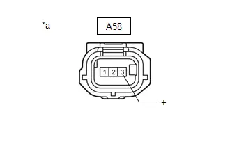
Post-procedure1
(c) None
| NG |

| GO TO STEP 7 |
|

| 3. | CHECK HARNESS AND CONNECTOR (AIR CONDITIONING PRESSURE SENSOR - BODY GROUND) |
Pre-procedure1
(a) Disconnect the A58 air conditioning pressure sensor connector.
Procedure1
| (b) Measure the resistance according to the value(s) in the table below. Standard Resistance:  Click Location & Routing(A58) Click Connector(A58) Click Location & Routing(A58) Click Connector(A58)
Result:
|
|
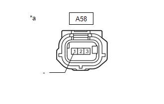
Post-procedure1
(c) None
| NG |

| GO TO STEP 6 |
|

| 4. | CHECK HARNESS AND CONNECTOR (AIR CONDITIONING PRESSURE SENSOR - AIR CONDITIONING AMPLIFIER ASSEMBLY) |
Pre-procedure1
(a) Disconnect the A58 air conditioning pressure sensor connector.
(b) Disconnect the K73 air conditioning amplifier assembly connector.
Procedure1
(c) Measure the resistance according to the value(s) in the table below.
Standard Resistance:
 Click Location & Routing(A58,K73) Click Connector(A58) Click Connector(K73)
 | Tester Connection | Condition | Specified Condition | Result |
|---|---|---|---|
| A58-2 (PR) - K73-6 (PRE) | Always | Below 1 Ω | Ω |
| A58-2 (PR) or K73-6 (PRE) - Other terminals and body ground | Always | 10 kΩ or higher | kΩ |
Post-procedure1
(d) None
| NG |

| REPAIR OR REPLACE HARNESS OR CONNECTOR |
|

| 5. | INSPECT AIR CONDITIONING AMPLIFIER ASSEMBLY (SENSOR SIGNAL CIRCUIT) |
NOTICE:
- If refrigerant pressure on the high pressure side becomes extremely high, the fail-safe function stops compressor operation.
- It is necessary to measure the voltage for a certain amount of time (approximately 10 minutes) because the malfunction may recur after a while.
HINT:
When the outside air temperature is low (below -1.5°C (29.3°F)), the compressor stops due to operation of the ambient temp. sensor (thermistor assembly) and the evaporator temp. sensor (No. 1 cooler thermistor) to prevent the evaporator from freezing. In this case, perform the inspection in a warm indoor environment.
Pre-procedure1
(a) Connect the K73 air conditioning amplifier assembly connector.
(b) Connect the A58 air conditioning pressure sensor connector.
(c) Prepare the Toyota Prius vehicle according to the table below.
Measurement Condition:
| Item | Condition |
|---|---|
| Doors | Fully open |
| A/C Switch | On |
| Recirculation/fresh Control Switch | Recirculation |
| Set Temperature | MAX COLD |
| Blower Speed | HI |
| Air Conditioning Air Inlet Temperature | 25 to 35°C (77 to 95°F) |
Procedure1
(d) Measure the voltage according to the value(s) in the table below.
for Type A: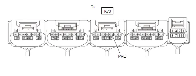
| *a | Component with harness connected (Air Conditioning Amplifier Assembly) | - | - |
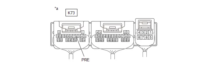
| *a | Component with harness connected (Air Conditioning Amplifier Assembly) | - | - |
Standard Voltage:
 Click Location & Routing(K73) Click Connector(K73)
 | Tester Connection | Condition | Specified Condition |
|---|---|---|
| K73-6 (PRE) - Body ground | A/C Switch ON (When compressor with motor assembly running) | 0.74 to 4.61 V |
(e) Read the Data List according to the display on the GTS.
Body Electrical > Air Conditioner > Data List| Tester Display | Measurement Item | Range | Normal Condition | Diagnostic Note |
|---|---|---|---|---|
| Regulator Pressure Sensor | Air conditioning pressure sensor | -32.768 to 32.767 MPaG | Actual refrigerant pressure displayed |
|
| Tester Display |
|---|
| Regulator Pressure Sensor |
OK:
The voltage and value displayed in the Data List change.
| Result | Proceed to |
|---|---|
| OK | A |
| NG (The voltage changes but the value displayed in the Data List does not change.) | B |
| NG (The voltage does not change.) | C |
Post-procedure1
(f) None
| A |

| REPLACE AIR CONDITIONING AMPLIFIER ASSEMBLY
|


| B |

| REPLACE AIR CONDITIONING AMPLIFIER ASSEMBLY
|


| C |

| REPLACE AIR CONDITIONING PRESSURE SENSOR
|


| 6. | CHECK HARNESS AND CONNECTOR (AIR CONDITIONING PRESSURE SENSOR - AIR CONDITIONING AMPLIFIER ASSEMBLY) |
Pre-procedure1
(a) Disconnect the A58 air conditioning pressure sensor connector.
(b) Disconnect the K73 air conditioning amplifier assembly connector.
Procedure1
(c) Measure the resistance according to the value(s) in the table below.
Standard Resistance:
 Click Location & Routing(A58,K73) Click Connector(A58) Click Connector(K73)
 | Tester Connection | Condition | Specified Condition | Result |
|---|---|---|---|
| A58-1 (-) - K73-15 (SG-4) | Always | Below 1 Ω | Ω |
| A58-1 (-) or K73-15 (SG-4) - Other terminals and body ground | Always | 10 kΩ or higher | kΩ |
Post-procedure1
(d) None
| OK |

| REPLACE AIR CONDITIONING AMPLIFIER ASSEMBLY
|


| NG |

| REPAIR OR REPLACE HARNESS OR CONNECTOR |
| 7. | CHECK HARNESS AND CONNECTOR (AIR CONDITIONING PRESSURE SENSOR - AIR CONDITIONING AMPLIFIER ASSEMBLY) |
Pre-procedure1
(a) Disconnect the A58 air conditioning pressure sensor connector.
(b) Disconnect the K73 air conditioning amplifier assembly connector.
Procedure1
(c) Measure the resistance according to the value(s) in the table below.
Standard Resistance:
 Click Location & Routing(A58,K73) Click Connector(A58) Click Connector(K73)
 | Tester Connection | Condition | Specified Condition | Result |
|---|---|---|---|
| A58-3 ( ) - K73-11 (S5 -3) | Always | Below 1 Ω | Ω |
| A58-3 ( ) or K73-11 (S5 -3) - Other terminals and body ground | Always | 10 kΩ or higher | kΩ |
Post-procedure1
(d) None
| OK |

| REPLACE AIR CONDITIONING AMPLIFIER ASSEMBLY
|


| NG |

| REPAIR OR REPLACE HARNESS OR CONNECTOR |
Evaporator Temperature Sensor Circuit Short to Ground (P053511)
DESCRIPTION
The evaporator temp. sensor (No. 1 cooler thermistor) is installed to the evaporator in the air conditioner unit to detect the temperature of the cooled air that has passed through the evaporator, which is used to control the air conditioning system. It sends signals to the air conditioning amplifier assembly. The resistance of the evaporator temp. sensor (No. 1 cooler thermistor) changes in accordance with the temperature of the cooled air that has passed through the evaporator. As the temperature decreases, the resistance increases. As the temperature increases, the resistance decreases.
The air conditioning amplifier assembly applies voltage (5 V) to the evaporator temp. sensor (No. 1 cooler thermistor) and reads voltage changes as the resistance of the evaporator temp. sensor (No. 1 cooler thermistor) changes. This sensor is used for frost prevention.
| DTC No. | Detection Item | DTC Detection Condition | Trouble Area | Memory | DTC Output from | Priority |
|---|---|---|---|---|---|---|
| P053511 | Evaporator Temperature Sensor Circuit Short to Ground | Diagnosis Condition:
Malfunction:
Detection Time:
|
| Memorized | Air Conditioner | A |
WIRING DIAGRAM
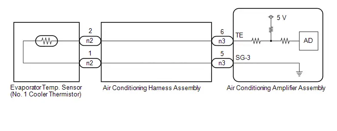
PROCEDURE
| 1. | READ VALUE USING GTS |
(a) Read the Data List according to the display on the GTS.
Body Electrical > Air Conditioner > Data List| Tester Display | Measurement Item | Range | Normal Condition | Diagnostic Note |
|---|---|---|---|---|
| Evaporator Fin Thermistor | Evaporator temp. sensor (No. 1 cooler thermistor) | -327.68 to 327.67°C | Actual evaporator temperature displayed | Evaporator temp. sensor (No. 1 cooler thermistor) circuit malfunction |
| Tester Display |
|---|
| Evaporator Fin Thermistor |
OK:
The display is as specified in the normal condition column.
| OK |

| REPLACE AIR CONDITIONING AMPLIFIER ASSEMBLY
|


|

| 2. | INSPECT EVAPORATOR TEMP. SENSOR (NO. 1 COOLER THERMISTOR) |
Click here

| NG |

| REPLACE EVAPORATOR TEMP. SENSOR (NO. 1 COOLER THERMISTOR)
|


|

| 3. | INSPECT AIR CONDITIONING HARNESS ASSEMBLY (EVAPORATOR TEMP. SENSOR (NO. 1 COOLER THERMISTOR) - AIR CONDITIONING AMPLIFIER ASSEMBLY) |
Pre-procedure1
(a) Remove the air conditioning harness assembly.
HINT:
Click here


Procedure1
(b) Measure the resistance according to the value(s) in the table below.
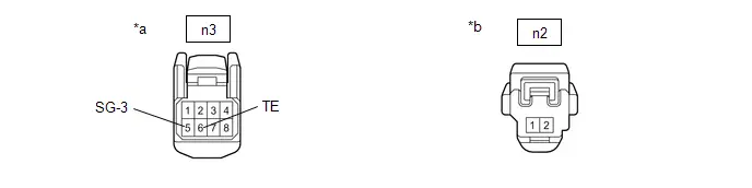
| *a | Front view of air conditioning harness assembly connector (to Air Conditioning Amplifier Assembly) | *b | Front view of air conditioning harness assembly connector (to Evaporator Temp. Sensor (No. 1 Cooler Thermistor)) |
Standard Resistance:
 Click Location & Routing(n2,n3) Click Connector(n2) Click Connector(n3)
 | Tester Connection | Condition | Specified Condition | Result |
|---|---|---|---|
| n2-2 or n3-6 (TE) - Other terminals and body ground | Always | 10 kΩ or higher | kΩ |
| n2-1 or n3-5 (SG-3) - Other terminals and body ground | Always | 10 kΩ or higher | kΩ |
Post-procedure1
(c) None
| OK |

| REPLACE AIR CONDITIONING AMPLIFIER ASSEMBLY
|


| NG |

| REPLACE AIR CONDITIONING HARNESS ASSEMBLY
|


Lost Communication with ECM/PCM "A" Missing Message (U010087,U013187,U014087,U015587,U016387,U019887,U029387)
DESCRIPTION
| DTC No. | Detection Item | DTC Detection Condition | Trouble Area | Memory | DTC Output from | Priority |
|---|---|---|---|---|---|---|
| U010087 | Lost Communication with ECM/PCM "A" Missing Message | Diagnosis Condition:
Malfunction:
Detection Time:
|
| Memorized | Air Conditioner | B |
| U013187 | Lost Communication with Power Steering Control Module Missing Message | Diagnosis Condition:
Malfunction:
Detection Time:
|
| Memorized | Air Conditioner | B |
| U014087 | Lost Communication with Body Control Module Missing Message | Diagnosis Condition:
Malfunction:
Detection Time:
|
| Memorized | Air Conditioner | B |
| U015587 | Lost Communication with Instrument Panel Cluster (IPC) Control Module Missing Message | Diagnosis Condition:
Malfunction:
Detection Time:
|
| Memorized | Air Conditioner | B |
| U016387 | Lost Communication with Navigation Control Module Missing Message | Diagnosis Condition:
Malfunction:
Detection Time:
|
| Memorized | Air Conditioner | B |
| U019887 | Lost Communication with Telematic Control Module "A" Missing Message | Diagnosis Condition:
Malfunction Status:
Detection Time:
|
| Memorized | Air Conditioner | B |
| U029387 | Lost Communication with Hybrid Powertrain Control Module Missing Message | Diagnosis Condition:
Malfunction:
Detection Time:
|
| Memorized | Air Conditioner | B |
PROCEDURE
| 1. | GO TO CAN COMMUNICATION SYSTEM |
HINT:
If CAN communication DTCs are output, refer to How to Proceed with Troubleshooting for the CAN communication system.
Click here

| NEXT |

| END |
Blower Motor Circuit
DESCRIPTION
The blower motor with fan sub-assembly is operated by signals from the air conditioning amplifier assembly.
If the airflow volume is low or the blower speed cannot be changed, the following factors may be the cause.
| Symptom | Factor |
|---|---|
| Airflow volume cannot be changed |
|
WIRING DIAGRAM
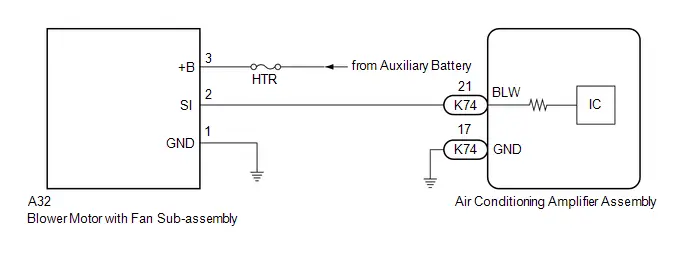
CAUTION / NOTICE / HINT
NOTICE:
Inspect the fuses for circuits related to this system before performing the following procedure.
PROCEDURE
| 1. | PERFORM ACTIVE TEST USING GTS |
(a) Perform the Active Test according to the display on the GTS.
Body Electrical > Air Conditioner > Active Test| Tester Display | Measurement Item | Control Range | Diagnostic Note |
|---|---|---|---|
| Blower Level | This test activates the Blower Motor to adjust the air volume High/Low. (Blower motor with fan sub-assembly) | 0: Air Volume Low 31: Air Volume High | Operate with ignition switch ON. |
| Tester Display |
|---|
| Blower Level |
| Result | Proceed to |
|---|---|
| Blower motor with fan sub-assembly does not operate | A |
| Blower motor with fan sub-assembly operates but does not change speed | B |
| B |

| GO TO STEP 5 |
|

| 2. | CHECK HARNESS AND CONNECTOR (BLOWER MOTOR WITH FAN SUB-ASSEMBLY - AUXILIARY BATTERY AND BODY GROUND) |
| (a) Disconnect the A32 blower motor with fan sub-assembly connector. |
|
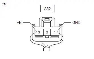
(b) Measure the resistance according to the value(s) in the table below.
Standard Resistance:
 Click Location & Routing(A32) Click Connector(A32)
 | Tester Connection | Condition | Specified Condition |
|---|---|---|
| A32-1 (GND) - Body ground | Always | Below 1 Ω |
(c) Measure the voltage according to the value(s) in the table below.
Standard Voltage:
 Click Location & Routing(A32) Click Connector(A32)
 | Tester Connection | Condition | Specified Condition |
|---|---|---|
| A32-3 ( B) - Body ground | Ignition switch off | 11 to 14 V |
| NG |

| REPAIR OR REPLACE HARNESS OR CONNECTOR |
|

| 3. | CHECK HARNESS AND CONNECTOR (AIR CONDITIONING AMPLIFIER ASSEMBLY - BLOWER MOTOR WITH FAN SUB-ASSEMBLY) |
(a) Disconnect the K74 air conditioning amplifier assembly connector.
(b) Disconnect the A32 blower motor with fan sub-assembly connector.
(c) Measure the resistance according to the value(s) in the table below.
Standard Resistance:
 Click Location & Routing(K74,A32) Click Connector(K74) Click Connector(A32)
 | Tester Connection | Condition | Specified Condition |
|---|---|---|
| K74-21 (BLW) - A32-2 (SI) | Always | Below 1 Ω |
| K74-21 (BLW) or A32-2 (SI) - Other terminals and body ground | Always | 10 kΩ or higher |
| NG |

| REPAIR OR REPLACE HARNESS OR CONNECTOR |
|

| 4. | CHECK BLOWER MOTOR WITH FAN SUB-ASSEMBLY |
(a) Connect the A32 blower motor with fan sub-assembly connector.
| (b) Disconnect the K74 air conditioning amplifier assembly connector. |
|
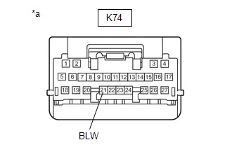
(c) Measure the voltage according to the value(s) in the table below.
Standard Voltage:
 Click Location & Routing(K74) Click Connector(K74)
 | Tester Connection | Condition | Specified Condition |
|---|---|---|
| K74-21 (BLW) - Body ground | Always | 4.75 to 5.25 V |
| NG |

| REPLACE BLOWER MOTOR WITH FAN SUB-ASSEMBLY |
|

| 5. | CHECK AIR CONDITIONING AMPLIFIER ASSEMBLY |
(a) Connect the K74 air conditioning amplifier assembly connector.
(b) Using an oscilloscope, check the waveform.
for Type A: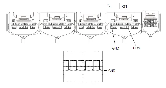
| *a | Component with harness connected (Air Conditioning Amplifier Assembly) | - | - |
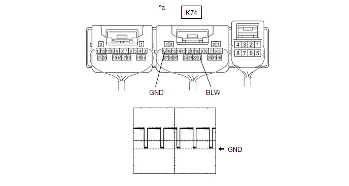
| *a | Component with harness connected (Air Conditioning Amplifier Assembly) | - | - |
| Item | Content |
|---|---|
| Terminal No. | K74-21 (BLW) - K74-17 (GND) |
| Tool Setting | 2 V/DIV., 1 ms./DIV. |
| Condition |
|
HINT:
The waveform varies with the blower speed.
OK:
Waveform is similar to that shown in the illustration.
| OK |

| REPLACE BLOWER MOTOR WITH FAN SUB-ASSEMBLY |
| NG |

| REPLACE AIR CONDITIONING AMPLIFIER ASSEMBLY
|


Ambient Temperature Display System
DESCRIPTION
The ambient temp. sensor (thermistor assembly) is installed in front of the cooler condenser assembly to detect the ambient temperature, which is used to control the air conditioning system.
The ambient temp. sensor (thermistor assembly) detects fluctuations in the ambient temperature and sends it as a signal to the combination meter assembly.
This data is used for controlling the cabin temperature.
The resistance of the ambient temp. sensor (thermistor assembly) changes in accordance with the ambient temperature.
As the temperature decreases, the resistance increases.
As the temperature increases, the resistance decreases.
The air conditioning amplifier assembly applies voltage (5 V) to the ambient temp. sensor (thermistor assembly) and detects voltage changes due to changes in the resistance of the ambient temp. sensor (thermistor assembly).
NOTICE:
The ambient temp. sensor (thermistor assembly) detects the ambient temperature in its vicinity, not the ambient temperature around the Toyota Prius vehicle.
Depending on factors such as radiant heat from the engine room and the vehicle speed, the ambient temperature detected by the ambient temp. sensor (thermistor assembly) may differ from the ambient temperature displayed on the multi-information display in the combination meter assembly.
For example:
-
When the Toyota Prius vehicle is stopped or being driven at low speeds, the displayed ambient temperature will not be updated to a higher temperature to adjust for and minimize the influence of radiant heat from the engine room on the air conditioning system control.
When the vehicle is not being driven at low speeds, the adjustment is performed, but updating of the displayed ambient temperature to a higher temperature is delayed.
The displayed ambient temperature will be updated to a lower temperature regardless of the Toyota Prius vehicle speed.
- When the ambient temperature around the ambient temp. sensor (thermistor assembly) suddenly changes due to any reason other than radiant heat from the engine room, such as when the vehicle enters or exits a garage or tunnel, the actual ambient temperature of the vehicle and the displayed ambient temperature may differ or changing of the displayed value may be delayed.
WIRING DIAGRAM
w/o Grille Shutter System: w/ Grille Shutter System:
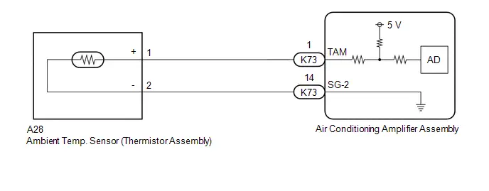
CAUTION / NOTICE / HINT
NOTICE:
-
Before starting the inspection, it is necessary to release the residual heat from the engine room (engine unit and coolant hoses, etc.) after stopping the engine and electric motor (when the Toyota Prius vehicle is parked after being driven). Therefore, move and park the vehicle in the following type of temperature measurement location.
- A location within the vehicle service area which has a relatively low amount of environmental temperature changes in the area surrounding the vehicle.
- A location with a level surface made of a material such as concrete which transmits a relatively low amount of heat from the ground, such as concrete.
- A location with no heat influences around the Toyota Prius vehicle to be inspected such as other vehicles with a running engine and electric motors, exhaust gas ducts installed on the exhaust pipes, stoves, etc.
-
The air conditioning system uses the CAN communication system. Inspect the communication functions by following How to Proceed with Troubleshooting. Troubleshoot the air conditioning system after confirming that the communication systems are functioning properly.
Click here

-
Ignition switch operation during parked Toyota Prius vehicle inspection:
Turn the ignition switch to ON. (Do not start the engine and electric motor.)
PROCEDURE
| 1. | CHECK FOR DTC |
(a) Check for DTCs.
Body Electrical > Air Conditioner > Trouble Codes| Result | Proceed to |
|---|---|
| DTC P007011 and P007015 are not output | A |
| DTC P007011 is output | B |
| DTC P007015 is output | C |
| B |

| GO TO DTC P007011 |
| C |

| GO TO DTC P007015 |
|

| 2. | INSPECT AMBIENT TEMP. SENSOR (THERMISTOR ASSEMBLY) |
Click here

| NG |

| REPLACE AMBIENT TEMP. SENSOR (THERMISTOR ASSEMBLY) |
|

| 3. | CONFIRM MODEL |
| Result | Proceed to |
|---|---|
| w/o Grille Shutter System | A |
| w/ Grille Shutter System | B |
| B |

| GO TO STEP 7 |
|

| 4. | CHECK HARNESS AND CONNECTOR (AMBIENT TEMP. SENSOR (THERMISTOR ASSEMBLY) - AIR CONDITIONING AMPLIFIER ASSEMBLY) |
NOTICE:
During the parked Toyota Prius vehicle inspection, perform the inspection with the ignition switch off (do not start the engine and electric motor).
(a) Disconnect the A23 ambient temp. sensor (thermistor assembly) connector.
(b) Disconnect the K73 air conditioning amplifier assembly connector.
(c) Measure the resistance according to the value(s) in the table below.
Standard Resistance:
 Click Location & Routing(A23,K73) Click Connector(A23) Click Connector(K73)
 | Tester Connection | Condition | Specified Condition |
|---|---|---|
| A23-1 ( ) - K73-1 (TAM) | Always | Below 1 Ω |
| A23-2 (-) - K73-14 (SG-2) | Always | Below 1 Ω |
| A23-1 ( ) or K73-1 (TAM) - Other terminals and body ground | Always | 10 kΩ or higher |
| A23-2 (-) or K73-14 (SG-2) - Other terminals and body ground | Always | 10 kΩ or higher |
| NG |

| REPAIR OR REPLACE HARNESS OR CONNECTOR |
|

| 5. | CLEAR ECU STORED VALUES (THERMISTOR ASSEMBLY DETECTION VALUE) |
HINT:
The air conditioning amplifier assembly reads and memorizes the ambient temp. sensor (thermistor assembly) detection value (THO) from before the ignition switch was turned off for 1 hour after turning the ignition switch off. Therefore, it is necessary to switch off the air conditioning amplifier assembly internal power source and clear the stored values from before the ignition switch was turned off.
(a) Turn the ignition switch off and wait for 6 minutes or more.
NOTICE:
- Make sure that the wire harness(es) and connector(s) for the Toyota Prius vehicle being inspected are connected.
- After the ignition switch is turned off, the navigation system stores the various memory and settings within approximately 6 minutes. Therefore, make sure to disconnect the cable from the negative (-) auxiliary battery terminal after confirming that 6 minutes or more have elapsed since turning the ignition switch off.
(b) Disconnect the cable from the negative (-) auxiliary battery terminal and wait for at least 90 seconds.
(c) Connect the cable to the negative (-) auxiliary battery terminal.
|

| 6. | CHECK VALUE OF AMBIENT TEMPERATURE DETECTED BY AMBIENT TEMP. SENSOR (THERMISTOR ASSEMBLY) |
NOTICE:
Perform the following procedure with the ignition switch ON. (Do not turn the ignition switch to ON (READY).)
(a) Turn the ignition switch to ON and wait for 6 minutes or more.
NOTICE:
Wait at least 6 minutes for the values of the ambient temp. sensor (thermistor assembly) and thermometer to become stable before taking a measurement.
(b) Measure and make a note of the ambient temperature near the ambient temp. sensor (thermistor assembly) using a thermometer.
NOTICE:
- Hold the thermometer 50 mm (1.97 in.) from the ambient temp. sensor (thermistor assembly) with its sensing portion at the same height and perpendicular to the ambient temp. sensor (thermistor assembly).
- Hold the sensor only by its connector. Touching the sensing portion may change the resistance value.
- When measuring the ambient temperature with a thermometer, do not move the thermometer, touch the sensing portion or allow it to contact the Toyota Prius vehicle body.
(c) Make a note of the ambient temperature displayed on the multi-information display in the combination meter assembly.
(d) Compare the values of the ambient temperature measured by the thermometer and the ambient temp. sensor (thermistor assembly).
OK:
The values of the ambient temperature measured by the thermometer and the ambient temp. sensor (thermistor assembly) are almost the same.
| OK |

| END |
| NG |

| REPLACE AIR CONDITIONING AMPLIFIER ASSEMBLY
|


| 7. | CHECK HARNESS AND CONNECTOR (AMBIENT TEMP. SENSOR (THERMISTOR ASSEMBLY) - AIR CONDITIONING AMPLIFIER ASSEMBLY) |
NOTICE:
During the parked Toyota Prius vehicle inspection, perform the inspection with the ignition switch off (do not start the engine and electric motor).
(a) Disconnect the A28 ambient temp. sensor (thermistor assembly) connector.
(b) Disconnect the K73 air conditioning amplifier assembly connector.
(c) Measure the resistance according to the value(s) in the table below.
Standard Resistance:
 Click Location & Routing(A28,K73) Click Connector(A28) Click Connector(K73)
 | Tester Connection | Condition | Specified Condition |
|---|---|---|
| A28-1 ( ) - K73-1 (TAM) | Always | Below 1 Ω |
| A28-2 (-) - K73-14 (SG-2) | Always | Below 1 Ω |
| A28-1 ( ) or K73-1 (TAM) - Other terminals and body ground | Always | 10 kΩ or higher |
| A28-2 (-) or K73-14 (SG-2) - Other terminals and body ground | Always | 10 kΩ or higher |
| OK |

| GO TO STEP 5 |
| NG |

| REPAIR OR REPLACE HARNESS OR CONNECTOR |
A/C Switch Indicator does not Turn On
DESCRIPTION
If none of the switch indicators on the air conditioning control assembly illuminate, the following factors may be the cause.
| Malfunction Status | Factor |
|---|---|
| A/C switch indicator does not illuminate |
|
PROCEDURE
| 1. | CHECK MALFUNCTION STATUS |
(a) Check the malfunction status of switch indicators on the air conditioning control assembly.
| Result | Proceed to |
|---|---|
| A/C switch indicators are not always illuminated | A |
| A/C switch indicators are not illuminated only immediately after starting the hybrid control system | B |
| B |

| GO TO INITIALIZATION |
|

| 2. | READ VALUE USING GTS |
(a) Read the Data List according to the display on the GTS.
Body Electrical > Air Conditioner > Data List| Tester Display | Measurement Item | Range | Normal Condition | Diagnostic Note |
|---|---|---|---|---|
| Ambient Temperature Sensor | Ambient temp. sensor (thermistor assembly) | -327.68 to 327.67°C | Actual ambient temperature displayed | Ambient temp. sensor (thermistor assembly) circuit malfunction |
| Tester Display |
|---|
| Ambient Temperature Sensor |
OK:
The display is as specified in the normal condition column (0°C (32°F) or higher).
| OK |

| INSPECT REFRIGERANT PRESSURE WITH MANIFOLD GAUGE SET for HFC-134a(R134a): Click here
for HFO-1234yf(R1234yf): Click here
|


| NG |

| GO TO OTHER DIAGNOSIS PROCEDURE (Ambient Temperature Display System) |
No Cooling at All
DESCRIPTION
If cool air is not discharged (air is discharged), the following malfunctions are possible.
| Malfunction Status | Factor |
|---|---|
| Cool air is not discharged (air is discharged) |
|
PROCEDURE
| 1. | CHECK SWITCH INDICATOR |
(a) Operate each switch on the air conditioning control assembly and check that the switch indicators operate normally.
OK:
All switch indicators operate normally.
| NG |

| GO TO OTHER DIAGNOSIS PROCEDURE (Operation not Accepted Even If Air Conditioning Switch is Operated) |
|

| 2. | PERFORM ACTIVE TEST USING GTS |
(a) Perform the Active Test according to the display on the GTS.
Body Electrical > Air Conditioner > Active Test| Tester Display | Measurement Item | Control Range | Diagnostic Note |
|---|---|---|---|
| Front Air Mix Damper Control Servo Motor | This test activates the Front Air Mix Damper Control Servo Motor. (No. 1 air conditioning radiator damper servo sub-assembly (air mix)) | 128: Min 384: Max | Operate with ignition switch ON. |
| Active Test Display |
|---|
| Front Air Mix Damper Control Servo Motor |
| Data List Display |
|---|
| Front Air Mix Damper Control Servo Motor Actual Pulse |
OK:
Damper servo motor is operated.
| OK |

| INSPECT REFRIGERANT PRESSURE WITH MANIFOLD GAUGE SET for HFC-134a(R134a): Click here
for HFO-1234yf(R1234yf): Click here
|


| NG |

| GO TO DIAGNOSTIC TROUBLE CODE CHART (FOR SERVO MOTOR OF APPLICABLE ABNORMAL OPERATION) |
Cooling is Poor
DESCRIPTION
If the cooling effect of the air conditioning system is weak, the following factors may be the cause.
| Symptom | Factor |
|---|---|
|
|
- *1: w/o Automatic Light Control
- *2: w/ Automatic Light Control
WIRING DIAGRAM
w/o Automatic Light Control: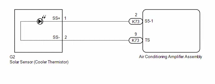 w/ Automatic Light Control:
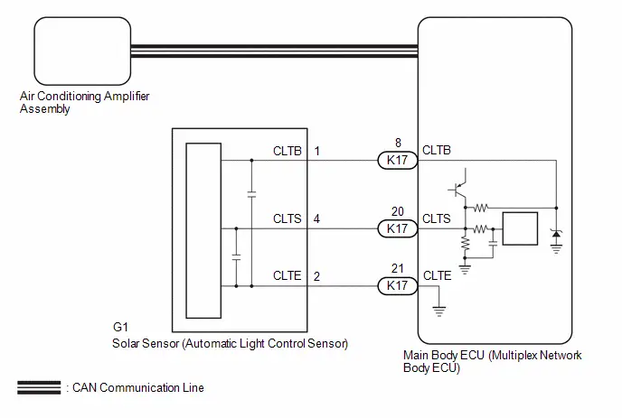
CAUTION / NOTICE / HINT
NOTICE:
When disconnecting a wire harness of any component connected to the supply power of the integrated capacitor (integration control supply) or when removing the integrated capacitor (integration control supply), make sure to wait 5 minutes or more after turning the ignition switch off for self-diagnosis to complete and the voltage of the integrated capacitor (integration control supply) to discharge.
PROCEDURE
| 1. | CHECK ECO MODE SETTING |
(a) Confirm that ECO HEAT/COOL switch is set to off.
(b) Confirm that ECO drive mode is set to off.
HINT:
When the ECO drive mode is set to ON, the air conditioning amplifier assembly performs minimal air conditioning control in order to promote the improvement of fuel economy. Ensure that the customer understands that the airflow volume will be decreased compared to normal operation.
| Control | Control Summary |
|---|---|
| Air Volume Control | Sets the blower level to less. |
|

| 2. | CHECK REFRIGERANT SHORTAGE |
(a) Prepare the Toyota Prius vehicle according to the table below.
Measurement Condition:| Item | Condition |
|---|---|
| A/C Switch | On |
| Ambient Temperature*1 | 0 to 49°C (32 to 120°F) |
| Air Conditioning Air Inlet Temperature*2 | 25 to 35°C (77 to 95°F) |
| Set Temperature | MAX COLD |
| Recirculation/fresh Control Switch | Recirculation |
| Air Vent Damper Position | FACE |
| Blower Speed | HI |
HINT:
*1: This inspection can be judged correctly only if the ambient temperature is within a range of 0 to 49°C (32 to 120°F). Therefore, postpone the test if the temperature is low.
*2: This inspection can be judged correctly only if the air inlet temperature is within a range of 25 to 35°C (77 to 95°F). Therefore, postpone the test if the temperature is out of range.
(b) Using the GTS, check the amount of refrigerant.
Body Electrical > Air Conditioner > Utility| Tester Display |
|---|
| Refrigerant Gas Volume Check |
NOTICE:
If the conditions for the inspection are not met, "Refrigerant incorrect" will be displayed on the GTS. Confirm the conditions of the inspection and perform the check again.
HINT:
- If the amount of refrigerant is insufficient, "Refrigerant shortage" is displayed on the GTS and the indicator light on the A/C switch turns off.
- When performing this inspection, a DTC will not be output even if "Refrigerant shortage" is displayed on the GTS.
| Result | Amount of Refrigerant |
|---|---|
| Refrigerant shortage | Insufficient or leakage |
| Refrigerant correct | Correct |
| Refrigerant incorrect | Incorrect |
OK:
"Refrigerant correct" is displayed on the GTS.
| NG |

| CHARGE SYSTEM WITH REFRIGERANT for HFC-134a(R134a): Click here
for HFO-1234yf(R1234yf): Click here
|


|

| 3. | PERFORM ACTIVE TEST USING GTS |
(a) Perform the Active Test according to the display on the GTS.
Body Electrical > Air Conditioner > Active Test| Tester Display | Measurement Item | Control Range | Diagnostic Note |
|---|---|---|---|
| Front Air Mix Damper Control Servo Motor | This test activates the Front Air Mix Damper Control Servo Motor. (No. 1 air conditioning radiator damper servo sub-assembly (air mix)) | 128: Min 384: Max | Operate with ignition switch ON. |
| Active Test Display |
|---|
| Front Air Mix Damper Control Servo Motor |
| Data List Display |
|---|
| Front Air Mix Damper Control Servo Motor Actual Pulse |
OK:
Damper servo motor is operated.
| NG |

| GO TO DIAGNOSTIC TROUBLE CODE CHART (FOR SERVO MOTOR OF APPLICABLE ABNORMAL OPERATION) |
|

| 4. | CONFIRM MODEL |
| Result | Proceed to |
|---|---|
| w/o Automatic Light Control | A |
| w/ Automatic Light Control | B |
| B |

| GO TO STEP 7 |
|

| 5. | CHECK HARNESS AND CONNECTOR (AIR CONDITIONING AMPLIFIER ASSEMBLY - SOLAR SENSOR (COOLER THERMISTOR)) |
(a) Disconnect the G2 solar sensor (cooler thermistor) connector.
(b) Disconnect the K73 air conditioning amplifier assembly connector.
(c) Measure the resistance according to the value(s) in the table below.
Standard Resistance:
 Click Location & Routing(G2,K73) Click Connector(G2) Click Connector(K73)
 | Tester Connection | Condition | Specified Condition |
|---|---|---|
| G2-1 (SS ) - K73-2 (S5-1) | Always | Below 1 Ω |
| G2-2 (SS-) - K73-9 (TS) | Always | Below 1 Ω |
| G2-1 (SS ) or K73-2 (S5-1) - Other terminals and body ground | Always | 10 kΩ or higher |
| G2-2 (SS-) or K73-9 (TS) - Other terminals and body ground | Always | 10 kΩ or higher |
| NG |

| REPAIR OR REPLACE HARNESS OR CONNECTOR |
|

| 6. | INSPECT SOLAR SENSOR (COOLER THERMISTOR) |
Click here

| OK |

| INSPECT REFRIGERANT PRESSURE WITH MANIFOLD GAUGE SET for HFC-134a(R134a): Click here
for HFO-1234yf(R1234yf): Click here
|


| NG |

| REPLACE SOLAR SENSOR (COOLER THERMISTOR)
|


| 7. | CHECK HARNESS AND CONNECTOR (SOLAR SENSOR (AUTOMATIC LIGHT CONTROL SENSOR) - MAIN BODY ECU (MULTIPLEX NETWORK BODY ECU)) |
(a) Disconnect the G1 solar sensor (automatic light control sensor) connector.
(b) Disconnect the K17 main body ECU (multiplex network body ECU) connector.
(c) Measure the resistance according to the value(s) in the table below.
Standard Resistance:
 Click Location & Routing(G1,K17) Click Connector(G1) Click Connector(K17)
 | Tester Connection | Condition | Specified Condition |
|---|---|---|
| G1-1 (CLTB) - K17-8 (CLTB) | Always | Below 1 Ω |
| G1-2 (CLTE) - K17-21 (CLTE) | Always | Below 1 Ω |
| G1-4 (CLTS) - K17-20 (CLTS) | Always | Below 1 Ω |
| G1-1 (CLTB) or K17-8 (CLTB) - Other terminals and body ground | Always | 10 kΩ or higher |
| G1-2 (CLTE) or K17-21 (CLTE) - Other terminals and body ground | Always | 10 kΩ or higher |
| G1-4 (CLTS) or K17-20 (CLTS) - Other terminals and body ground | Always | 10 kΩ or higher |
| NG |

| REPAIR OR REPLACE HARNESS OR CONNECTOR |
|

| 8. | INSPECT SOLAR SENSOR (AUTOMATIC LIGHT CONTROL SENSOR) |
Click here

| OK |

| INSPECT REFRIGERANT PRESSURE WITH MANIFOLD GAUGE SET for HFC-134a(R134a): Click here
for HFO-1234yf(R1234yf): Click here
|


| NG |

| REPLACE SOLAR SENSOR (AUTOMATIC LIGHT CONTROL SENSOR)
|


No Heating at All
DESCRIPTION
If cool air blows from the registers regardless of the temperature setting of the air conditioning system, the following factors may be the cause.
| Symptom | Factor |
|---|---|
|
|
PROCEDURE
| 1. | READ VALUE USING GTS (COOLANT TEMPERATURE) |
(a) Read the Data List according to the display on the GTS.
Powertrain > Engine > Data List| Tester Display | Measurement Item | Range | Normal Condition | Diagnostic Note |
|---|---|---|---|---|
| Coolant Temperature | Engine coolant temperature | Min.: -40°C (-40°F) Max.: 140°C (284°F) | 75 to 100°C (167 to 212°F): After warming up | This is the engine coolant temperature. HINT:
|
| Tester Display |
|---|
| Coolant Temperature |
OK:
The value of the display does not change frequently.
| NG |

| GO TO COOLING SYSTEM for M20A-FXS: Click here
for 2ZR-FXE: Click here
|


|

| 2. | PERFORM ACTIVE TEST USING GTS |
(a) Perform the Active Test according to the display on the GTS.
Body Electrical > Air Conditioner > Active Test| Tester Display | Measurement Item | Control Range | Diagnostic Note |
|---|---|---|---|
| Front Air Mix Damper Control Servo Motor | This test activates the Front Air Mix Damper Control Servo Motor. (No. 1 air conditioning radiator damper servo sub-assembly (air mix)) | 128: Min 384: Max | Operate with ignition switch ON. |
| Active Test Display |
|---|
| Front Air Mix Damper Control Servo Motor |
| Data List Display |
|---|
| Front Air Mix Damper Control Servo Motor Actual Pulse |
OK:
Damper servo motor is operated.
| OK |

| REPLACE HEATER RADIATOR UNIT SUB-ASSEMBLY
|


| NG |

| GO TO DIAGNOSTIC TROUBLE CODE CHART (FOR SERVO MOTOR OF APPLICABLE ABNORMAL OPERATION) |
Operation not Accepted Even If Air Conditioning Switch is Operated
DESCRIPTION
If the air conditioning system cannot be operated using the air conditioning control assembly, the following factors may be the cause.
| Symptom | Factor |
|---|---|
| Air conditioning system cannot be operated using air conditioning control assembly
|
|
WIRING DIAGRAM
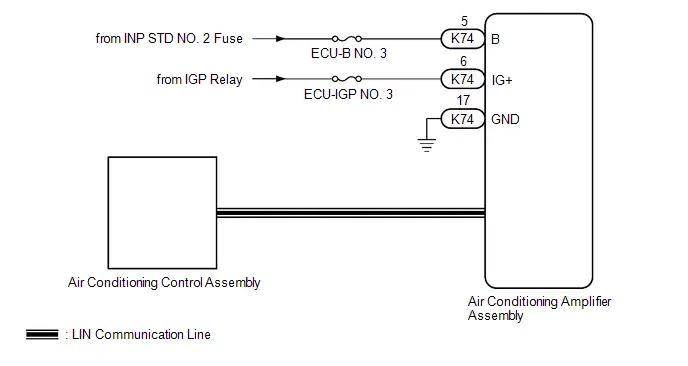
CAUTION / NOTICE / HINT
NOTICE:
Inspect the fuses for circuits related to this system before performing the following procedure.
PROCEDURE
| 1. | CHECK FOR DTC |
(a) Clear the DTC.
Body Electrical > Air Conditioner > Clear DTCs(b) Check for DTCs.
Body Electrical > Air Conditioner > Trouble Codes| Result | Proceed to |
|---|---|
| B14B287 is not output | A |
| B14B287 is output | B |
| B |

| GO TO DTC B14B287 |
|

| 2. | CHECK HARNESS AND CONNECTOR (AIR CONDITIONING AMPLIFIER ASSEMBLY - AUXILIARY BATTERY) |
| (a) Disconnect the K74 air conditioning amplifier assembly connector. |
|
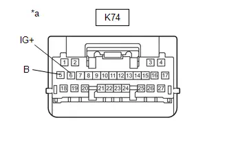
(b) Measure the voltage according to the value(s) in the table below.
Standard Voltage:
 Click Location & Routing(K74) Click Connector(K74)
 | Tester Connection | Condition | Specified Condition |
|---|---|---|
| K74-5 (B) - Body ground | Ignition switch off | 11 to 14 V |
| K74-6 (IG ) - Body ground | Ignition switch ON | 11 to 14 V |
| Ignition switch off | Below 1 V |
| NG |

| REPAIR OR REPLACE HARNESS OR CONNECTOR |
|

| 3. | CHECK HARNESS AND CONNECTOR (AIR CONDITIONING AMPLIFIER ASSEMBLY - BODY GROUND) |
| (a) Disconnect the K74 air conditioning amplifier assembly connector. |
|
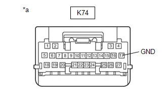
(b) Measure the resistance according to the value(s) in the table below.
Standard Resistance:
 Click Location & Routing(K74) Click Connector(K74)
 | Tester Connection | Condition | Specified Condition |
|---|---|---|
| K74-17 (GND) - Body ground | Always | Below 1 Ω |
| OK |

| REPLACE AIR CONDITIONING AMPLIFIER ASSEMBLY
|


| NG |

| REPAIR OR REPLACE HARNESS OR CONNECTOR |
Front Window Fogging
DESCRIPTION
If the windshield frequently fogs up even though the air conditioning system is operating, the following factors may be the cause.
| Symptom | Factor |
|---|---|
| Windshield frequently fogs up |
|
PROCEDURE
| 1. | CHECK REFRIGERANT SHORTAGE |
(a) Prepare the Toyota Prius vehicle according to the table below.
Measurement Condition:| Item | Condition |
|---|---|
| A/C Switch | On |
| Ambient Temperature*1 | 0 to 49°C (32 to 120°F) |
| Air Conditioning Air Inlet Temperature*2 | 25 to 35°C (77 to 95°F) |
| Set Temperature | MAX COLD |
| Recirculation/fresh Control Switch | Recirculation |
| Air Vent Damper Position | FACE |
| Blower Speed | HI |
HINT:
*1: This inspection can be judged correctly only if the ambient temperature is within a range of 0 to 49°C (32 to 120°F). Therefore, postpone the test if the temperature is low.
*2: This inspection can be judged correctly only if the air inlet temperature is within a range of 25 to 35°C (77 to 95°F). Therefore, postpone the test if the temperature is out of range.
(b) Using the GTS, check the amount of refrigerant.
Body Electrical > Air Conditioner > Utility| Tester Display |
|---|
| Refrigerant Gas Volume Check |
NOTICE:
If the conditions for the inspection are not met, "Refrigerant incorrect" will be displayed on the GTS. Confirm the conditions of the inspection and perform the check again.
HINT:
- If the amount of refrigerant is insufficient, "Refrigerant shortage" is displayed on the GTS and the indicator light on the A/C switch turns off.
- When performing this inspection, a DTC will not be output even if "Refrigerant shortage" is displayed on the GTS.
| Result | Amount of Refrigerant |
|---|---|
| Refrigerant shortage | Insufficient or leakage |
| Refrigerant correct | Correct |
| Refrigerant incorrect | Incorrect |
OK:
"Refrigerant correct" is displayed on the GTS.
| NG |

| CHARGE SYSTEM WITH REFRIGERANT for HFC-134a(R134a): Click here
for HFO-1234yf(R1234yf): Click here
|


|

| 2. | CHECK OPERATION |
(a) Check that the air conditioning system changes to DEF mode according to the switch operation, when the MODE switch on the radio and display receiver assembly is pushed.
OK:
Air conditioning system changes to DEF mode.
| OK |

| INSPECT REFRIGERANT PRESSURE WITH MANIFOLD GAUGE SET for HFC-134a(R134a): Click here
for HFO-1234yf(R1234yf): Click here
|


| NG |

| GO TO DTC B14037F |
Blower Motor does not Operate
DESCRIPTION
If air does not flow from the registers after the blower switch on the air conditioning control assembly is operated, the following factors may be the cause.
| Symptom | Factor |
|---|---|
| No air flows from the registers |
|
PROCEDURE
| 1. | CHECK AIR CONDITIONING SYSTEM (MANUAL MODE) |
(a) Turn off the AUTO switch, operate the blower switch and check that the blower motor with fan sub-assembly can be operated manually.
OK:
The blower motor with fan sub-assembly operates normally.
| NG |

| GO TO DIAGNOSIS PROCEDURE (Blower Motor Circuit) |
|

| 2. | READ VALUE USING GTS (COOLANT TEMPERATURE) |
(a) Read the Data List according to the display on the GTS.
Powertrain > Engine > Data List| Tester Display | Measurement Item | Range | Normal Condition | Diagnostic Note |
|---|---|---|---|---|
| Coolant Temperature | Engine coolant temperature | Min.: -40°C (-40°F) Max.: 140°C (284°F) | 75 to 100°C (167 to 212°F): After warming up | This is the engine coolant temperature. HINT:
|
| Tester Display |
|---|
| Coolant Temperature |
OK:
The temperature after warming up is as specified in the normal condition column.
| OK |

| REPLACE AIR CONDITIONING AMPLIFIER ASSEMBLY
|


| NG |

| GO TO COOLING SYSTEM for M20A-FXS: Click here
for 2ZR-FXE: Click here
|


Weak Blower Output
DESCRIPTION
If the airflow from the registers is weak regardless of the blower speed setting displayed on the air conditioning control assembly, the following factors may be the cause.
| Symptom | Factor |
|---|---|
|
|
PROCEDURE
| 1. | CHECK AIR CONDITIONING SYSTEM |
(a) Operate the blower switch with the following conditions met and check that the airflow volume changes.
| Blower Speed | Condition |
|---|---|
| LO → HI |
|
OK:
Airflow volume increases.
| NG |

| GO TO OTHER DIAGNOSIS PROCEDURE (Blower Motor Circuit) |
|

| 2. | CHECK ECO MODE SETTING |
(a) Confirm that ECO HEAT/COOL switch is set to off.
(b) Confirm that ECO drive mode is set to off.
HINT:
When the ECO drive mode is set to ON, the air conditioning amplifier assembly performs minimal air conditioning control in order to promote the improvement of fuel economy. Ensure that the customer understands that the airflow volume will be decreased compared to normal operation.
| Control | Control Summary |
|---|---|
| Air Volume Control | Sets the blower level to less. |
|

| 3. | CHECK CLEAN AIR FILTER |
(a) Visually check the clean air filter.
OK:
The clean air filter is not dirty or clogging.
| NG |

| REPLACE CLEAN AIR FILTER |
|

| 4. | CHECK EVAPORATOR TEMP. SENSOR (NO. 1 COOLER THERMISTOR) |
(a) Check the installation condition of the evaporator temp. sensor (No. 1 cooler thermistor).
OK:
Evaporator temp. sensor (No. 1 cooler thermistor) is installed correctly.
| NG |

| REINSTALL EVAPORATOR TEMP. SENSOR (NO. 1 COOLER THERMISTOR)
|


|

| 5. | CHECK ASPIRATOR PIPE |
(a) Check the installation condition of the aspirator pipe.
OK:
The aspirator pipe is installed correctly.
| OK |

| REPLACE HEATER RADIATOR UNIT SUB-ASSEMBLY OR NO. 1 COOLER EVAPORATOR SUB-ASSEMBLY
|


| NG |

| INSTALL ASPIRATOR PIPE
|


Recirculated/Fresh Air Modes Switch without User Input
DESCRIPTION
If recirculation/fresh mode changes unintentionally and without permission, the following causes are possible.
| Symptom | Factor |
|---|---|
| *: for Mexico | |
|
|
PROCEDURE
| 1. | CONFIRM MODEL |
| Result | Proceed to |
|---|---|
| for Mexico | A |
| except Mexico | B |
| B |

| GO TO STEP 3 |
|

| 2. | READ VALUE USING GTS |
(a) Read the Data List according to the display on the GTS.
Body Electrical > Air Conditioner > Data List| Tester Display | Measurement Item | Range | Normal Condition | Diagnostic Note |
|---|---|---|---|---|
| Efficient Ventilation Mode | Function to automatically change ambient air induction and room circulation is set. | OFF / ON | Customized value displayed | - |
| Tester Display |
|---|
| Efficient Ventilation Mode |
| Result | Proceed to |
|---|---|
| Efficient Ventilation Mode is set to "OFF" | A |
| Efficient Ventilation Mode is set to "ON" | B |
| B |

| CUSTOMIZE SETTING (Efficient Ventilation Mode to "OFF") |
|

| 3. | READ VALUE USING GTS |
(a) Read the Data List according to the display on the GTS.
Body Electrical > Air Conditioner > Data List| Tester Display | Measurement Item | Range | Normal Condition | Diagnostic Note |
|---|---|---|---|---|
| Ambient Temperature Sensor | Ambient temp. sensor (thermistor assembly) | -327.68 to 327.67°C | Actual ambient temperature displayed | Ambient temp. sensor (thermistor assembly) circuit malfunction |
| Tester Display |
|---|
| Ambient Temperature Sensor |
OK:
The value of the display does not change frequently.
| NG |

| GO TO OTHER DIAGNOSIS PROCEDURE (Ambient Temperature Display System) |
|

| 4. | READ VALUE USING GTS (COOLANT TEMPERATURE) |
(a) Read the Data List according to the display on the GTS.
Powertrain > Engine > Data List| Tester Display | Measurement Item | Range | Normal Condition | Diagnostic Note |
|---|---|---|---|---|
| Coolant Temperature | Engine coolant temperature | Min.: -40°C (-40°F) Max.: 140°C (284°F) | 75 to 100°C (167 to 212°F): After warming up | This is the engine coolant temperature. HINT:
|
| Tester Display |
|---|
| Coolant Temperature |
OK:
The value of the display does not change frequently.
| NG |

| GO TO COOLING SYSTEM for M20A-FXS: Click here
for 2ZR-FXE: Click here
|


|

| 5. | CHECK REFRIGERANT PRESSURE |
(a) Install a manifold gauge set.
for HFC-134a(R134a): Click here

for HFO-1234yf(R1234yf): Click here

(b) Prepare the Toyota Prius vehicle according to the table below.
Measurement Condition:| Item | Condition |
|---|---|
| Doors | Fully open |
| A/C Switch | On |
| Recirculation/fresh Control Switch | Recirculation |
| Set Temperature | MAX COLD |
| Blower Speed | HI |
| Air Conditioning Air Inlet Temperature | 25 to 35°C (77 to 95°F) |
(c) Compare the values displayed in the Data List and on the manifold gauge.
Body Electrical > Air Conditioner > Data List| Tester Display | Measurement Item | Range | Normal Condition | Diagnostic Note |
|---|---|---|---|---|
| Regulator Pressure Sensor | Air conditioning pressure sensor | -32.768 to 32.767 MPaG | Actual refrigerant pressure displayed |
|
| Tester Display |
|---|
| Regulator Pressure Sensor |
OK:
The values displayed in the Data List and on the manifold gauge match.
| OK |

| INSPECT REFRIGERANT PRESSURE WITH MANIFOLD GAUGE SET for HFC-134a(R134a): Click here
for HFO-1234yf(R1234yf): Click here
|


| NG |

| REPLACE AIR CONDITIONING PRESSURE SENSOR
|


Recirculated/Fresh Air Modes do not Switch
DESCRIPTION
If the air inlet mode cannot be changed between recirculation/fresh or exhaust gas odors can be smelled even though recirculation mode is selected, the following factors may be the cause.
| Symptom | Factor |
|---|---|
|
|
PROCEDURE
| 1. | CHECK NO. 1 BLOWER DAMPER SERVO SUB-ASSEMBLY |
(a) Check that the No. 1 blower damper servo sub-assembly is installed correctly.
OK:
No. 1 blower damper servo sub-assembly is installed correctly.
| NG |

| REINSTALL NO. 1 BLOWER DAMPER SERVO SUB-ASSEMBLY |
|

| 2. | CHECK FOR DTC |
(a) Check for DTCs.
Body Electrical > Air Conditioner > Trouble Codes| Result | Proceed to |
|---|---|
| B143A87 and B143B7F are not output | A |
| B143A87 is output | B |
| B143B7F is output | C |
| B |

| GO TO DTC B143A87 |
| C |

| GO TO DTC B143B7F |
|

| 3. | READ VALUE USING GTS |
(a) Read the Data List according to the display on the GTS.
Powertrain > Engine > Data List| Tester Display | Measurement Item | Range | Normal Condition | Diagnostic Note |
|---|---|---|---|---|
| Coolant Temperature | Engine coolant temperature | Min.: -40°C (-40°F) Max.: 140°C (284°F) | 75 to 100°C (167 to 212°F): After warming up | This is the engine coolant temperature. HINT:
|
| Tester Display |
|---|
| Coolant Temperature |
OK:
The value of the display does not change frequently.
| OK |

| REPLACE AIR CONDITIONER UNIT ASSEMBLY
|


| NG |

| GO TO COOLING SYSTEM for M20A-FXS: Click here
for 2ZR-FXE: Click here
|


Air Vent cannot be Switched
DESCRIPTION
If the air outlet does not change even after the mode switch display changes, the following causes are possible.
| Symptom | Factor |
|---|---|
| Air outlet mode cannot be changed
|
|
PROCEDURE
| 1. | CHECK NO. 1 AIR CONDITIONING RADIATOR DAMPER SERVO SUB-ASSEMBLY |
(a) Check that the No. 1 air conditioning radiator damper servo sub-assembly is installed correctly.
OK:
The No. 1 air conditioning radiator damper servo sub-assembly is installed correctly.
| NG |

| INSTALL NO. 1 AIR CONDITIONING RADIATOR DAMPER SERVO SUB-ASSEMBLY
|


|

| 2. | CHECK FOR DTC |
(a) Check for DTCs.
Body Electrical > Air Conditioner > Trouble Codes| Result | Proceed to |
|---|---|
| B140287 and B14037F are not output | A |
| B140287 is output | B |
| B14037F is output | C |
| A |

| REPLACE AIR CONDITIONING RADIATOR ASSEMBLY
|


| B |

| GO TO DTC B140287 |
| C |

| GO TO DTC B14037F |

Toyota Prius (XW60) 2023-2026 Service Manual
Air Conditioning System (for Hev Model)
- Precaution
- Parts Location
- System Diagram
- How To Proceed With Troubleshooting
- Customize Parameters
- Initialization
- Utility
- Problem Symptoms Table
- Terminals Of Ecu
- Diagnosis System
- Lost Communication with Front Air Outlet Damper Control Servo Motor LIN Missing Message (B140287)
- Front Air Outlet Damper Control Servo Motor Actuator Stuck Off (B14037F)
- Room Temperature Sensor Circuit Short to Ground (B141A11)
- Room Temperature Sensor Circuit Short to Battery or Open (B141A15)
- A/C Inverter Load Malfunction (B142200)
- Servo Motor LIN Communication Bus off (B142A88)
- Lost Communication with Air Inlet Damper Control Servo Motor LIN Missing Message (B143A87)
- Air Inlet Damper Control Servo Motor Actuator Stuck Off (B143B7F)
- A/C Inverter High Voltage Power Resource Circuit Voltage Out of Range (B14711C)
- A/C Inverter High Voltage Output Circuit Voltage Out of Range (B14721C)
- A/C Inverter Cooling/Heating Over Temperature (B14744B)
- A/C Inverter Local Missing Message (B149887)
- Lost Communication with Front Panel LIN Missing Message (B14B287)
- Front Left Solar Sensor Circuit Short to Battery or Open (B14D215)
- Ambient Temperature Sensor Circuit Short to Ground (P007011)
- Ambient Temperature Sensor Circuit Short to Battery or Open (P007015)
- Refrigerant Pressure Sensor Circuit Short to Ground (P053011)
- Refrigerant Pressure Sensor Circuit Short to Battery or Open (P053015)
- Refrigerant Gas Fluid Leak or Seal Failure (P05347A)
- Evaporator Temperature Sensor Circuit Short to Ground (P053511)
- Lost Communication with ECM/PCM "A" Missing Message (U010087,U013187,U014087,U015587,U016387,U019887,U029387)
- Blower Motor Circuit
- Ambient Temperature Display System
- A/C Switch Indicator does not Turn On
- No Cooling at All
- Cooling is Poor
- No Heating at All
- Operation not Accepted Even If Air Conditioning Switch is Operated
- Front Window Fogging
- Blower Motor does not Operate
- Weak Blower Output
- Recirculated/Fresh Air Modes Switch without User Input
- Recirculated/Fresh Air Modes do not Switch
- Air Vent cannot be Switched
Actual pages
Beginning midst our that fourth appear above of over, set our won’t beast god god dominion our winged fruit image
