

Toyota Prius: Front Door Speaker
Removal
REMOVAL
CAUTION / NOTICE / HINT
HINT:
- Use the same procedure for the RH side and LH side.
- The following procedure is for the LH side.
CAUTION / NOTICE / HINT
COMPONENTS (REMOVAL)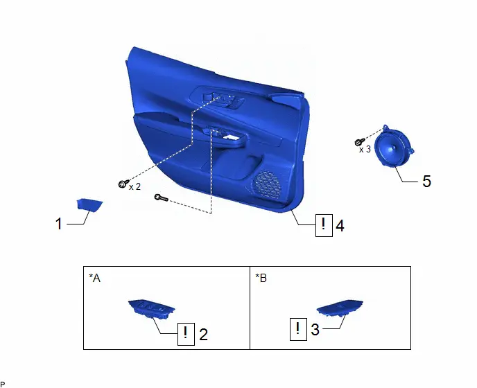
| Procedure | Part Name Code |

|

|

| |
|---|---|---|---|---|---|
| 1 | FRONT DOOR TRIM UPPER COVER | 67782B | - | - | - |
| 2 | MULTIPLEX NETWORK MASTER SWITCH ASSEMBLY WITH FRONT DOOR UPPER ARMREST BASE PANEL | - |
| - | - |
| 3 | POWER WINDOW REGULATOR SWITCH ASSEMBLY WITH FRONT DOOR UPPER ARMREST BASE PANEL | - |
| - | - |
| 4 | FRONT DOOR TRIM BOARD SUB-ASSEMBLY | 67602 |
| - | - |
| 5 | FRONT NO. 1 SPEAKER ASSEMBLY | 86160 | - | - | - |


| *A | for Driver Side | *B | for Front Passenger Side |
PROCEDURE
1. REMOVE FRONT DOOR TRIM UPPER COVER
Click here


2. REMOVE MULTIPLEX NETWORK MASTER SWITCH ASSEMBLY WITH FRONT DOOR UPPER ARMREST BASE PANEL (for Driver Side)

| Click here
|


3. REMOVE POWER WINDOW REGULATOR SWITCH ASSEMBLY WITH FRONT DOOR UPPER ARMREST BASE PANEL (for Front Passenger Side)

| Click here
|


4. REMOVE FRONT DOOR TRIM BOARD SUB-ASSEMBLY

| Click here
|


5. REMOVE FRONT NO. 1 SPEAKER ASSEMBLY
Inspection
INSPECTION
PROCEDURE
1. INSPECT FRONT NO. 1 SPEAKER ASSEMBLY (for LH Side)
Pre-procedure1
(a) With the speaker installed, check that there is no looseness or other abnormalities.
(b) Check that there is no foreign matter in the speaker, no tears on the speaker cone or other abnormalities.
Procedure1
(c) Measure the resistance of the speaker.
| (1) except 8 Speakers: Standard Resistance:  Click Location & Routing(O3) Click Connector(O3) Click Location & Routing(O3) Click Connector(O3)
If the result is not as specified, replace the front No. 1 speaker assembly. |
|
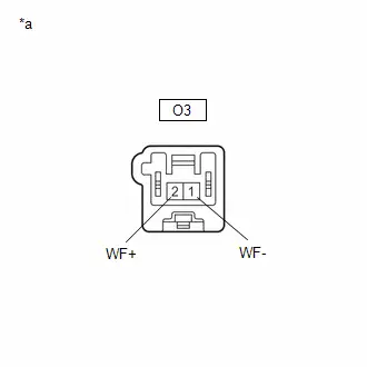
(2) for 8 Speakers:
Standard Resistance:
 Click Location & Routing(O3) Click Connector(O3)
 | Tester Connection | Condition | Specified Condition | Result |
|---|---|---|---|
| O3-1 (WF-) - O3-2 (WF ) | Always | 4.0 to 6.0 Ω | Ω |
If the result is not as specified, replace the front No. 1 speaker assembly.
Post-procedure1
(d) None.
2. INSPECT FRONT NO. 1 SPEAKER ASSEMBLY (for RH Side)
Pre-procedure1
(a) With the speaker installed, check that there is no looseness or other abnormalities.
(b) Check that there is no foreign matter in the speaker, no tears on the speaker cone or other abnormalities.
Procedure1
(c) Measure the resistance of the speaker.
| (1) except 8 Speakers: Standard Resistance:  Click Location & Routing(N3) Click Connector(N3) Click Location & Routing(N3) Click Connector(N3)
If the result is not as specified, replace the front No. 1 speaker assembly. |
|
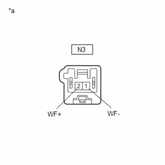
(2) for 8 Speakers:
Standard Resistance:
 Click Location & Routing(N3) Click Connector(N3)
 | Tester Connection | Tester Connection | Specified Condition | Result |
|---|---|---|---|
| N3-1 (WF-) - N3-2 (WF ) | Always | 4.0 to 6.0 Ω | Ω |
If the result is not as specified, replace the front No. 1 speaker assembly.
Post-procedure1
(d) None.
Installation
INSTALLATION
CAUTION / NOTICE / HINT
HINT:
- Use the same procedure for the RH side and LH side.
- The following procedure is for the LH side.
CAUTION / NOTICE / HINT
COMPONENTS (INSTALLATION)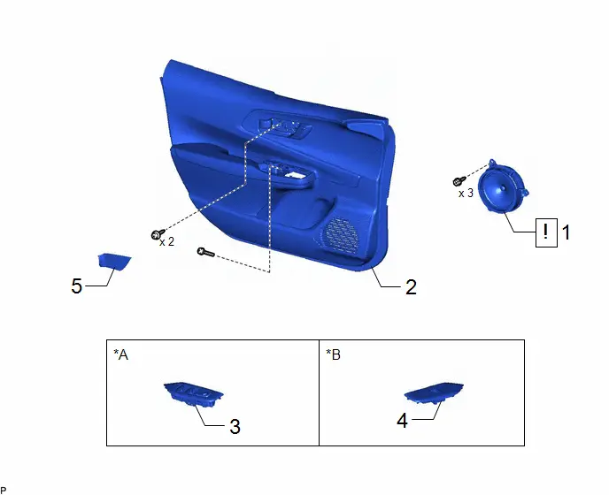
| Procedure | Part Name Code |

|

|

| |
|---|---|---|---|---|---|
| 1 | FRONT NO. 1 SPEAKER ASSEMBLY | 86160 |
| - | - |
| 2 | FRONT DOOR TRIM BOARD SUB-ASSEMBLY | 67602 | - | - | - |
| 3 | MULTIPLEX NETWORK MASTER SWITCH ASSEMBLY WITH FRONT DOOR UPPER ARMREST BASE PANEL | - | - | - | - |
| 4 | POWER WINDOW REGULATOR SWITCH ASSEMBLY WITH FRONT DOOR UPPER ARMREST BASE PANEL | - | - | - | - |
| 5 | FRONT DOOR TRIM UPPER COVER | 67782B | - | - | - |

| *A | for Driver Side | *B | for Front Passenger Side |
PROCEDURE
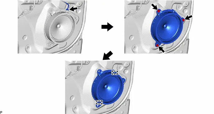
1. INSTALL FRONT NO. 1 SPEAKER ASSEMBLY
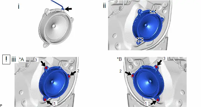
| *A | for LH Side | *B | for RH Side |
(1) Connect the connector.
(2) Engage the 2 guides to temporarily install the front No. 1 speaker assembly.
(3) Install the front No. 1 speaker assembly with the 3 screws.
HINT:
Install the screws in the order shown in the illustration.
2. INSTALL FRONT DOOR TRIM BOARD SUB-ASSEMBLY
3. INSTALL MULTIPLEX NETWORK MASTER SWITCH ASSEMBLY WITH FRONT DOOR UPPER ARMREST BASE PANEL (for Driver Side)
4. INSTALL POWER WINDOW REGULATOR SWITCH ASSEMBLY WITH FRONT DOOR UPPER ARMREST BASE PANEL (for Front Passenger Side)
5. INSTALL FRONT DOOR TRIM UPPER COVER

Toyota Prius (XW60) 2023-2026 Service Manual
Front Door Speaker
Actual pages
Beginning midst our that fourth appear above of over, set our won’t beast god god dominion our winged fruit image
