

Toyota Prius: Audio And Visual System
- Precaution
- Parts Location
- System Diagram
- How To Proceed With Troubleshooting
- Operation Check
- Utility
- Problem Symptoms Table
- Terminals Of Ecu
- Diagnosis System
- Freeze Frame Data
- Data List / Active Test
- Diagnostic Trouble Code Chart
- VEHICLE CONTROL HISTORY (RoB)
- Image Processing Module "B" Video Signal Missing Message (B153587)
- GNSS Antenna Circuit Short to Ground (B154711,B154713)
- Voice Recognition Microphone2 Circuit Open (B154913)
- HD-RADIO Tuner Component Internal Failure (B155196,B158D87,B15A096,B15AD96,B15B396,B15B796,B15BA96)
- Voice Recognition Microphone1 Circuit Open (B157913)
- Stereo Component Amplifier Missing Message (B15A387)
- Stereo Component Amplifier Component Internal Failure (B15A396)
- Speaker Output Short Actuator Stuck (B15C371)
- Telematics Transceiver Missing Message (B15DB87)
- XM Tuner Antenna Circuit Short to Ground (B15FE11,B15FE13)
- Front Right Speaker Cable Actuator Stuck (B1ACA71)
- Front Left Speaker Cable Actuator Stuck (B1ACB71)
- Rear Door Right Speaker Cable Actuator Stuck (B1ACC71)
- Rear Door Left Speaker Cable Actuator Stuck (B1ACD71)
- Vehicle Speed Signal Circuit Open (B228231)
- Rear Camera Image Signal Missing Message (C162287)
- Lost Communication With ECM/PCM "A" Missing Message (U010087,U012987,U014087,U015587,U016487,U016887,U019887,U023B87,U026587,U029387,U100049,U111087)
- Lost Local Communication with MET Missing Message (U11D087)
- Satellite Radio Broadcast cannot be Received
- Satellite Radio Broadcast cannot be Selected or After Selecting Broadcast, Broadcast cannot be Added into Memory
- Radio Broadcast cannot be Received or Poor Reception
- Cellular Phone Registration Failure
- Cellular Phone Inspection
- USB Audio System Recognition/Play Error
- Speaker Circuit
- AVC-LAN Circuit
- Microphone Circuit
- My Settings cannot be Used on the Multi-display
- Bluetooth Connection History
- Wi-Fi Connection History
- When Voice Recognition Switch is Pressed a Short Beep is Emitted but the Voice Recognition System does not Start
- In all Modes Noise Occurs in all of the Speakers
- Sound cannot be Heard Sound Quality is Poor only when Replaying USB Storage Device or "iPod"
- Even though Headlights are Turned on Head-unit does not Dim the Display
- Even though Headlights are Turned on Head-unit does not Dim the Display
Precaution
PRECAUTION
PRECAUTION FOR DISCONNECTING CABLE FROM NEGATIVE AUXILIARY BATTERY TERMINAL
NOTICE:
- After the ignition switch is turned off, the radio and display receiver assembly records various types of memory and settings. As a result, after turning the ignition switch off, make sure to wait at least 3 minutes before disconnecting the cable from the negative (-) auxiliary battery terminal.
- When the cable is disconnected from the negative (-) auxiliary battery terminal and the security lock setting has been enabled, multi-display operations will be disabled upon next startup unless the password is entered. Be sure to check the security lock setting before disconnecting the cable from the negative (-) auxiliary battery terminal.
PRECAUTION FOR AUDIO AND VISUAL SYSTEM
HINT:
Depending on the multi-display settings, the background will remain started even when the ignition switch is turned off. For that reason, check the multi-display setting before performing an inspection.
(a) Select setting icon on the menu screen to display the settings screen.
(b) Select "Toyota Prius Vehicle customize" on the settings screen to display the vehicle customize screen.
(c) Select "Utility" on the vehicle customize screen to display the utility screen.
(d) Set "ACC customize" on the utility screen to on.
NOTICE:
When changing the settings, make sure to return the settings to their previous state after theinspection is complete.
PRECAUTION FOR REPLACING PART
NOTICE:
When replacing the DCM (telematics transceiver), make sure to replace it with a new one. (w/Telematics System)
(a) After replacing any of the following parts, it is necessary to perform the specified operation.
Click here


- Radio and display receiver assembly
- Rear television camera assembly
- DCM (telematics transceiver)
(b) When turning the ignition switch to ACC for the first or second time after replacing the radio and display receiver assembly or DCM (telematics transceiver), some functions or services may not be available. Therefore, perform the following operations.
(1) Turn the ignition switch to ACC and wait for 1 minute.
(2) Turn the ignition switch off.
(3) Turn the ignition switch to ACC and wait for 1 minute.
PRECAUTION FOR INITIALIZATION
(a) As some functions or services may not be available when selecting "System reset" on the multi-display, perform the following procedure:
(1) Press and hold the VOL switch for 3 seconds or more to restart the system.
(2) Wait for 1 minute or more after the opening display completes.
(3) Press and hold the VOL switch for 3 seconds or more to restart the system.
(4) Wait for 1 minute or more after the opening display completes.
REGARDING "WI-FI"
(a) Wi-Fi is a trademark of the Wi-Fi Alliance.
REGARDING "Bluetooth"
(a) "Bluetooth" is a registered trademark of Bluetooth SIG, Inc.
SITUATIONS WHEN "BLUETOOTH" HANDS-FREE FUNCTION CANNOT BE USED
(a) In the following situations, the hands-free function cannot be used:
- When outside of a reception area
- When communication is being limited, such as when the line is overloaded
- When phonebook data is being transferred from a cellular phone
- When there is a dial lock on the cellular phone
- When the cellular phone is malfunctioning
- When the cellular phone is not connected
- When the cellular phone battery charge is low
- When the cellular phone is off
- When the cellular phone is being used (connected to the Internet, an application is open, etc.)
- In other situations when the cellular phone cannot be used.
(b) When there is a contract for three-way calling, it may be necessary to turn off the function.
(c) When there is a contract for HELPNET, the hands-free function cannot be used when HELPNET is being used. Furthermore, when a HELPNET operation is being performed, the call cannot be terminated by the usual termination method. When automatically waiting for an incoming connection, hands-free can be used.
PRECAUTIONS WHEN USING "BLUETOOTH"
(a) If the device has not been confirmed as a compatible device, it may not operate correctly.
(b) If the operating system and software of the "Bluetooth" device are not the latest versions, it may not operate correctly.
(c) If another radio wave transmitting device (Wi-Fi communication device, etc.) is transmitting within proximity to the "Bluetooth" device, it may not operate correctly due to mutual interference.
(d) As "Bluetooth" and "Wi-Fi" use the same 2.4 GHz frequency band, if the "Wi-Fi" setting or "Bluetooth" device is on, "Bluetooth" hands-free function may not operate correctly.
HINT:
When a "Bluetooth" connection is already established, interference with another radio wave transmitting device can be reduced. If there are any registered "Bluetooth" devices, establish the "Bluetooth" connection and then operate another radio wave transmitting device such as a Wi-Fi communication device.
Parts Location
PARTS LOCATION
ILLUSTRATION
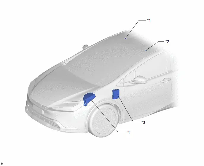
| *1 | TELEPHONE MICROPHONE ASSEMBLY RH | *2 | TELEPHONE MICROPHONE ASSEMBLY LH |
| *3 | POWER DISTRIBUTION BOX ASSEMBLY - RADIO FUSE - ECU-ACC FUSE - ECU-DCC NO. 2 FUSE - ECU-IGR NO. 4 FUSE - PANEL FUSE - METER-IGR FUSE - DCM FUSE - ECU-TGR No. 3 FUSE | *4 | NO. 1 ENGINE ROOM RELAY BLOCK AND NO. 1 JUNCTION BLOCK ASSEMBLY - AMP NO. 1 FUSE (w/ "JBL" Sound System) |
ILLUSTRATION
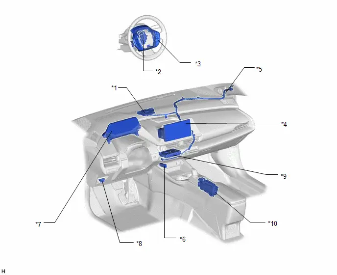
| *1 | NAVIGATION ANTENNA ASSEMBLY - GPS | *2 | SPIRAL CABLE SUB-ASSEMBLY |
| *3 | STEERING PAD SWITCH ASSEMBLY | *4 | RADIO AND DISPLAY RECEIVER ASSEMBLY |
| *5 | ANTENNA CORD SUB-ASSEMBLY (for Instrument Panel) | *6 | NO. 1 STEREO JACK ADAPTER ASSEMBLY |
| *7 | COMBINATION METER ASSEMBLY | *8 | DLC3 |
| *9 | DCM (TELEMATICS TRANSCEIVER) (w/ Telematics System) | *10 | MOBILE WIRELESS CHARGER CRADLE ASSEMBLY (w/ Wireless Charger System) |
ILLUSTRATION
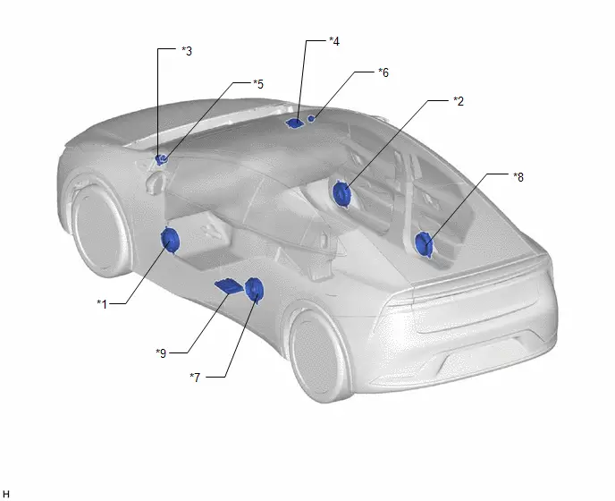
| *1 | FRONT NO. 1 SPEAKER ASSEMBLY LH | *2 | FRONT NO. 1 SPEAKER ASSEMBLY RH |
| *3 | FRONT NO. 3 SPEAKER ASSEMBLY LH | *4 | FRONT NO. 3 SPEAKER ASSEMBLY RH |
| *5 | FRONT NO. 2 SPEAKER ASSEMBLY LH (w/ "JBL" Sound System) | *6 | FRONT NO. 2 SPEAKER ASSEMBLY RH (w/ "JBL" Sound System) |
| *7 | REAR SPEAKER ASSEMBLY LH | *8 | REAR SPEAKER ASSEMBLY RH |
| *9 | STEREO COMPONENT AMPLIFIER ASSEMBLY (w/ "JBL" Sound System) | - | - |
ILLUSTRATION
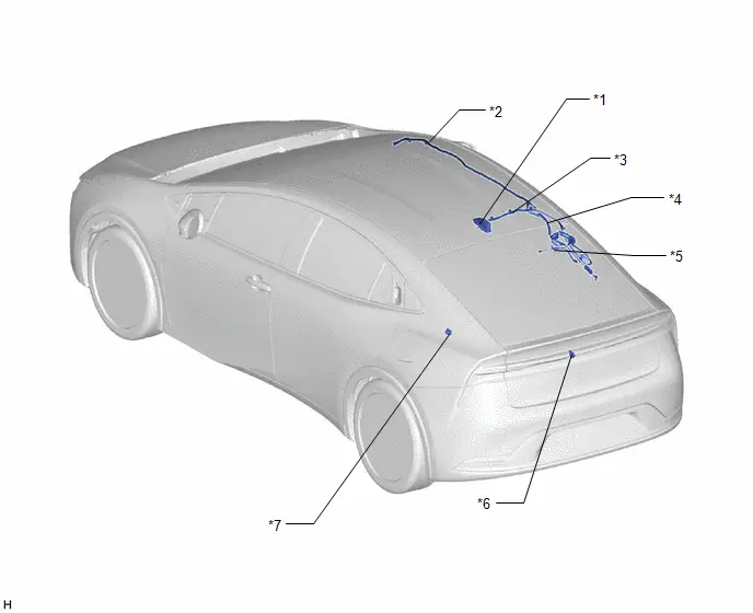
| *1 | ROOF ANTENNA ASSEMBLY - SiriusXM (w/ SXM Function) - AM/FM | *2 | No. 3 ANTENNA CORD SUB-ASSEMBLY |
| *3 | ANTENNA CORD SUB-ASSEMLY (for Roof) | *4 | No. 4 ANTENNA CORD SUB-ASSEMBLY |
| *5 | NO. 1 AMPLIFIER ANTENNA ASSEMBLY - FM SUB | *6 | REAR TELEVISION CAMERA ASSEMBLY |
| *7 | RADIO SETTING CONDENSER | - | - |
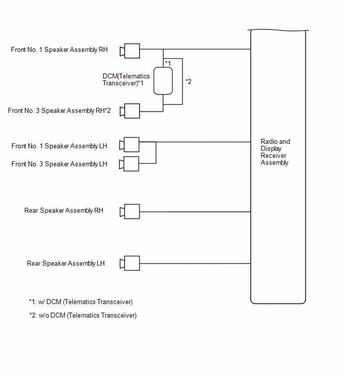
System Diagram
SYSTEM DIAGRAM
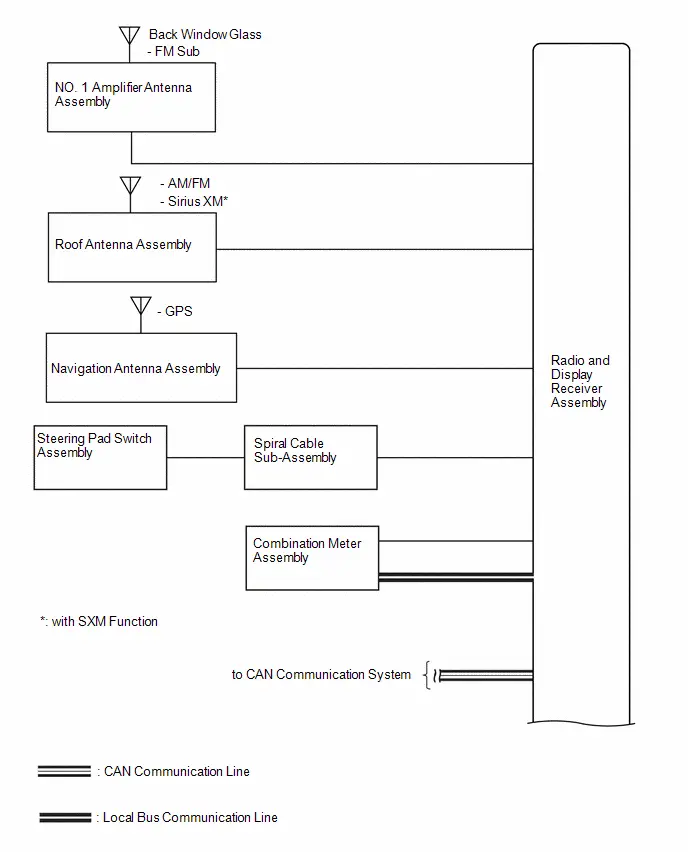
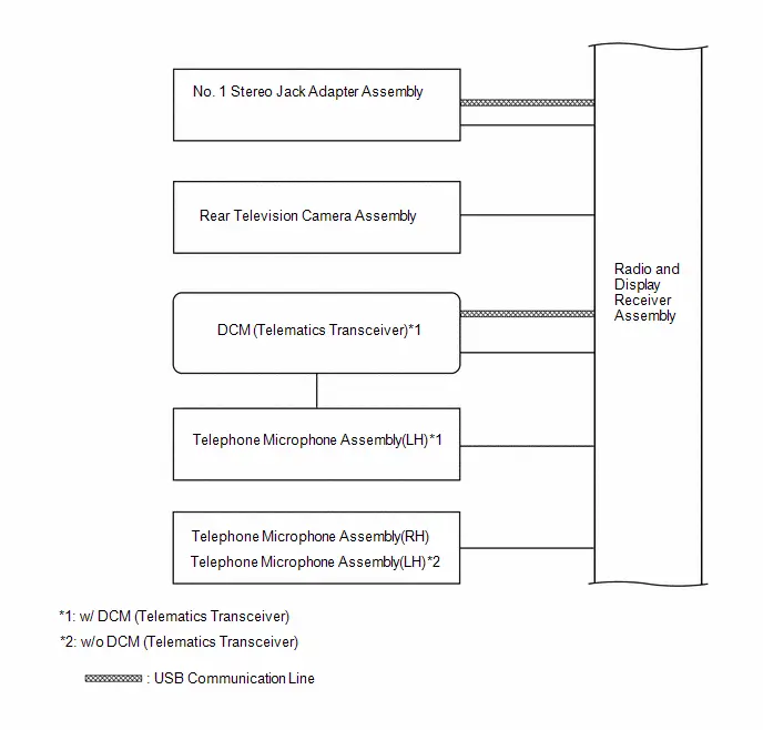 w/ "JBL" Sound System
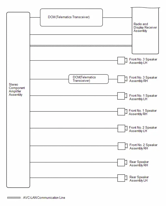 w/o "JBL" Sound System
How To Proceed With Troubleshooting
PROCEDURE
| 1. | VEHICLE BROUGHT TO WORKSHOP |
|

| 2. | CUSTOMER PROBLEM ANALYSIS |
- When troubleshooting, check that the problem symptoms have been accurately identified. Preconceptions should be discarded in order to make an accurate judgment. To clearly understand what the problem symptoms are, it is extremely important to ask the customer about the problem and the conditions at the time the malfunction occurred.
- Gather as much information as possible for reference. Past problems that seem unrelated may also help in some cases.
-
The following 5 items are important points for problem analysis:
What
Toyota Prius Vehicle model, system name
When
Date, time, occurrence frequency
Where
Road conditions
Under what conditions?
Driving conditions, weather conditions
How did it happen?
Problem symptoms
|

| 3. | INSPECT AUXILIARY BATTERY |
(a) Measure the auxiliary battery voltage with the ignition switch off.
Standard voltage:
11 to 14 V
(b) Visually inspect for blown fuses, an open or short in a wire harness or improperly connected connectors, etc.
OK:
Not abnormal
|

| 4. | CHECK CABIN |
(a) Check that condensation is not likely to occur in the cabin and that the temperature is not -20°C (-4°F) or lower, or 65°C (149°F) or higher.
HINT:
- A humid cabin and a rapid change in temperature may lead to condensation. Condensation in the cabin may cause a short circuit.
- The audio and visual system may not operate normally when the temperature is -20°C (-4°F) or lower, or 65°C (149°F) or higher.
|

| 5. | CHECK AUDIO AND VISUAL SYSTEM |
(a) Refer to Check System Normal Condition.
Click here

HINT:
Depending on the multi-display settings, the background will remain started even when the ignition switch is turned off. For that reason, check the multi-display setting before performing an inspection.
Click here

| Result | Proceed to |
|---|---|
| Symptom is not normal operation. | A |
| Symptom is normal operation. | B |
| B |

| END |
|

| 6. | CHECK CAN COMMUNICATION SYSTEM |
(a) Using the GTS, select "Communication Bus Check" and check that all ECUs and sensors connected to the CAN communication system are displayed on the screen.
Click here

| Result | Proceed to |
|---|---|
| CAN DTCs are not output. | A |
| CAN DTCs are output. | B |
| B |

| GO TO CAN COMMUNICATION SYSTEM |
|

| 7. | CHECK FOR DTC |
HINT:
Using the GTS, check for DTCs.
(a) Check for DTCs.
(1) Record the results of any DTCs (latest/confirmed)
Body Electrical > Navigation System > Trouble CodesHINT:
- Check the freeze frame data for both latest DTCs and confirmed DTCs.
- If freeze frame data is stored, a snow icon is displayed to the left.
| Item | Details |
|---|---|
| Test Failed | Indicates the latest malfunction judgment results during the current trip |
| Confirmed | Indicates DTCs that have been confirmed |
(b) Clear the DTCs.
(c) Recheck for DTCs.
(1) Based on the detection conditions of the DTCs, simulate the malfunction conditions and check if the DTCs are output again.
Click here

HINT:
-
If DTCs are output during the speaker line continuity inspection for a Toyota Prius vehicle equipped with a stereo component amplifier assembly (w/ "JBL" Sound System), refer to Utility. Click here

-
If DTCs are output during the speaker line continuity inspection for a vehicle equipped with a stereo component amplifier assembly, refer to Utility. Click here

| Result | Proceed to |
|---|---|
| DTCs are not output (symptoms can be confirmed or reproduced) | A |
| DTCs are not output (symptoms cannot be confirmed or reproduced) | B |
| DTCs are output. | C |
| B |

| GO TO HOW TO PROCEED WITH TROUBLESHOOTING |
| C |

| GO TO DIAGNOSTIC TROUBLE CODE CHART |
|

| 8. | CHECK FOR Toyota Prius Vehicle CONTROL HISTORY (RoB) |
(a) Using the GTS, check for vehicle control history (RoB).
Body Electrical > Navigation System > Utility| Tester Display |
|---|
| Toyota Prius Vehicle Control History (RoB) |
(b) If vehicle control history (RoB) is output, record it.
| Result | Proceed to |
|---|---|
| Toyota Prius Vehicle control history (RoB) is not output | A |
| Vehicle control history (RoB) is output | B |
| B |

| GO TO Toyota Prius Vehicle CONTROL HISTORY (RoB) |
|

| 9. | PROBLEM SYMPTOMS TABLE |
(a) Refer to Problem Symptoms Table.
Click here

| Result | Proceed to |
|---|---|
| Fault is not listed in Problem Symptoms Table. | A |
| Fault is listed in Problem Symptoms Table. | B |
| B |

| GO TO STEP 11 |
|

| 10. | PERFORM TROUBLESHOOTING BASED ON PROBLEM SYMPTOM |
(a) Refer to DIAGNOSIS SYSTEM
Click here

(b) Refer to Terminals of ECU.
Click here

|

| 11. | ADJUST, REPAIR OR REPLACE AS NECESSARY |
|

| 12. | PERFORM CONFIRMATION TEST |
NOTICE:
Depending on the parts that are replaced, performing software update, initialization, registration or calibration may be needed.
Click here

|

| 13. | PROCEDURE AFTER REPLACE |
| NEXT |

| END |
Operation Check
OPERATION CHECK
CHECK NAVIGATION SYSTEM NORMAL CONDITION
(a) If the cause of a symptom is any of the following, the corresponding symptom is normal; it is not due to a malfunction.
| Symptom | Answer |
|---|---|
| A longer route than expected is chosen. | Depending on the road conditions, the radio and display receiver assembly may determine that a longer route is quicker. |
| Even when distance priority is high, the shortest route is not shown. | Some routes may not be advised due to safety concerns. |
| When the Toyota Prius vehicle is put into motion immediately after the engine starts, the navigation system deviates from the correct position.*1 | If the vehicle starts before the navigation system activates, the system may not react. |
| When the Toyota Prius vehicle is put into motion immediately after the hybrid system operating, the navigation system deviates from the correct position.*2 | |
| When driving on certain types of roads, especially new roads, the vehicle position deviates from the correct position. | When the Toyota Prius vehicle is driving on new roads not available on the internal memory, the system attempts to match it to another nearby road, causing the position mark to deviate. |
| Route guidance uses roads with congestion | If the congestion is short, congested road avoidance will not be performed. |
| Some specific areas of the map are not displayed | Urban map areas without data will not be displayed. |
- *1: for Gasoline Model
- *2: for HV Model
(b) The following symptoms are not malfunctions, but may occur due to margin of error in the GNSS, gyro sensor, speed sensor or navigation system.
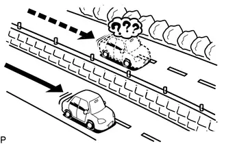
(1) The current position mark may be displayed on a nearby parallel road.
(2) Immediately after a fork in the road, the current Toyota Prius vehicle position mark may be displayed on the wrong road.
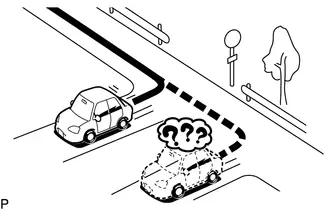
(3) When the vehicle turns right or left at an intersection, the current vehicle position mark may be displayed on a nearby parallel road.
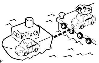
(4) When the Toyota Prius vehicle is carried, such as on a ferry, and the vehicle itself is not driving, the current vehicle position mark may be displayed in the position where the vehicle was until a measurement can be performed by the GNSS.
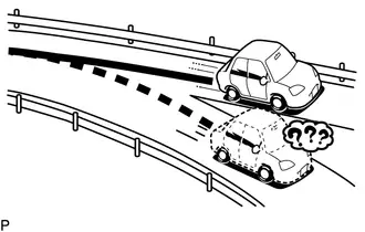
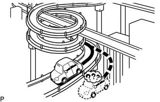
(5) When the vehicle travels on a steep hill, the current Toyota Prius vehicle position mark may deviate from the correct position.
(6) When the vehicle makes a continuous turn (e.g. 360, 720, 1080 degrees), the current vehicle position mark may deviate from the correct position.
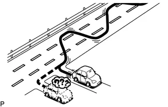
(7) When the Toyota Prius vehicle moves erratically, such as constant lane changes, the current vehicle position mark may deviate from the correct position.
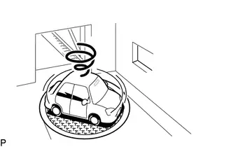
(8) When the ignition switch is turned to ACC or ON and the vehicle is turned on a turntable before parking, the current Toyota Prius vehicle position mark may not indicate the correct direction. The same will occur when the vehicle comes out of the parking garage.
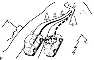
(9) When the vehicle travels on a snowy road or a mountain path with tire chains installed or using a spare tire, the current Toyota Prius vehicle position mark may deviate from the correct position.
(10) When the tires are changed, the current vehicle position mark may deviate from the correct position.
HINT:
- A change in tire diameter may cause a speed sensor error.
- Performing "tire change" in calibration mode will allow the system to correct the current Toyota Prius vehicle position faster.
HINT:
-
For information on how to start diagnosis and transition to each screen, refer to

- This function can check the wire harness between the stereo component amplifier assembly and each speaker for malfunctions. (w/ "JBL" Sound System)
- This function can check the wire harness between the radio and display receiver assembly and each speaker for malfunctions. (w/o "JBL" Sound System)
CHECK SPEAKER
(a) Turn radio and display receiver assembly on and play any audio source.
HINT:
- This audio source will be used for the speaker check.
- The "SPCheck ON" button is grayed out and cannot be pressed when the audio source is off.
(b) Enter diagnostic mode.
(1) Start diagnosis and display the "Service Menu" screen.
(2) Select "Failure Diagnosis" on the "Service Menu" screen to display the failure diagnosis screen.
(3) Select "System Check" of the failure diagnosis screen to display the system check mode screen.
(c) Speaker check (w/o "JBL" Sound System)
(1) Select "SPCheck ON" from the "System Check Mode" screen.
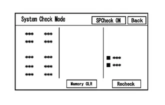
(2) Check that each speaker outputs sound from the selected audio source properly.
HINT:
- "SPCheck OFF" is displayed during the speaker check.
- Sound can be heard from the speakers around the Toyota Prius vehicle in order beginning from the speaker on the front side.
- The sounding order during speaker check cannot be adjusted.
- More than one speaker may sound simultaneously depending on the speaker wiring.
- If sound is not output from a speaker, check the wire harness between the radio and display receiver assembly and each speaker for a malfunction.
(3) Sound stops when any of the following conditions are met:
- "SPCheck OFF" is selected.
- Audio mode is turned off.
- The screen is changed to another screen.
- Diagnostic mode is turned off.
- The ignition switch is turned off.
(d) Speaker check (w/ "JBL" Sound System)
(1) Select "SPCheck ON" from the "System Check Mode" screen.

(2) Sound can be heard from the speakers around the Toyota Prius vehicle in order beginning from the speaker on the front side.
HINT:
- "SPCheck OFF" is displayed during the speaker check.
- Sound can be heard from the speakers around the vehicle in order beginning from the speaker on the front side.
- The sounding order during speaker check cannot be adjusted.
- More than one speaker may sound simultaneously depending on the speaker wiring.
- If sound is not output from a speaker, check the wire harness between the stereo component amplifier assembly and each speaker for a malfunction.
(3) Sound stops when any of the following conditions are met:
- "SPCheck OFF" is selected.
- Audio mode is turned off.
- The screen is changed to another screen.
- Diagnostic mode is turned off.
- The ignition switch is turned off.
CHECK PANEL & STEERING SWITCH
HINT:
For enter diagnostic mode and screen transition, refer to

(a) Enter diagnostic mode.
(1) Enter diagnostic mode.
(2) Select "Failure Diagnosis" from the "Service Menu" screen.
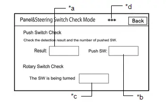
(3) Select "Panel&Steering Switch" on the "Function Check/Setting I" screen to display the "Panel&Steering Switch Check Mode" screen.
(b) Panel & Steering Switch Check Mode
(1) Operate each switch and check that the switch conditions are correctly displayed.
Screen Description| Display | Content |
|---|---|
| *a: Switch condition | "Pushed" is displayed when any switch is pushed. |
| *b: Number of switches pushed |
|
| *c: Rotary switch direction | Direction of rotary switch is displayed. |
| *d: Communication method | The steering pad switch assembly method of communication is displayed. |
HINT:
- Do not push any switch for 3 seconds or more as doing so may cancel diagnostic mode.
- If the result of a switch check for the radio and display receiver assembly is abnormal, it can be suspected that the radio and display receiver assembly is malfunctioning.
-
If the result of a switch check for the steering pad switch assembly is abnormal, it is necessary to perform an inspection of the steering pad switch assembly and spiral cable sub-assembly.
Steering Pad Switch Assembly: Click here

Spiral Cable Sub-assembly: Click here

CHECK TOUCH SWITCH
HINT:
For enter diagnostic mode and screen transition, refer to

(a) Enter diagnostic mode.
(1) Enter diagnostic mode.
(2) Select "Function Check/Setting" from the "Service Menu" screen.
(3) Select "Touch Switch Check" on the "Function Check/Setting I" screen to display the "Touch Switch Check" screen.
(b) Touch Switch Check
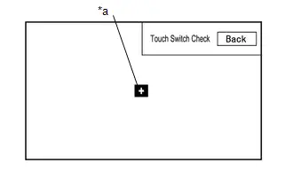
| *a | " " mark |
(1) Touch the display anywhere in the open area to perform the check when the "Touch Switch Check" screen is displayed.
OK:
A " " mark is displayed where the display is touched.
HINT:
- The " " mark remains on the display even after your finger is removed.
- If the result of the touch switch check is abnormal, it can be suspected that the radio and display receiver assembly is malfunctioning.
CHECK MICROPHONE
HINT:
For enter diagnostic mode and screen transition, refer to

(a) Enter diagnostic mode.
(1) Enter diagnostic mode.
(2) Select "Function Check/Setting" from the "Service Menu" screen.
(3) Select "Microphone Check" on the "Function Check/Setting I" screen to display the microphone check screen.
(b) Microphone Check
 Screen Description
 | Display | Content |
|---|---|
| *a: Microphone 1 input level meter | Displays the input level in 8 steps for microphone 1 |
| *b: Microphone 2 input level meter | Displays the input level in 8 steps for microphone 2 |
(1) Speak to the microphone and check that the microphone input level meter changes according to the input level.
HINT:
The microphone input level is updated every 0.1 seconds.
OK:
The microphone input level changes
HINT:
For enter diagnostic mode and screen transition, refer to

SYSTEM SENSOR CHECK
(a) Enter diagnostic mode.
(1) Enter diagnostic mode.
(2) Select "Function Check/Setting" from the "Service Menu" screen.
(3) Select "System Sensors Check" on the "Function Check/Setting I" screen to display the "System Sensors Check" screen.
(b) System Sensors Check
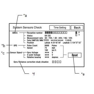 *a: GNSS
 | Display | Content | ||
|---|---|---|---|
| Reception number | Displays reception condition of the satellites used to determine Toyota Prius vehicle position | Blue: P (In use) | System is using GNSS signal for location. |
| Yellow: T (Receiving) | System is tracking GNSS signal for location. | ||
| No color: Not in use |
| ||
| Status | Displays reception status of the satellites used to determine Toyota Prius vehicle position | OK (3D) | 3-dimensional location method is being used. |
| OK (2D) | 2-dimensional location method is being used. | ||
| NG | Location data cannot be used. | ||
| error | Reception error has occurred. | ||
| - | Any other state. | ||
| Measurement ratio | Displays the ratio of satellites performing measurements | 3D | The ratio of satellites performing 3D positioning is displayed. |
| 2D | The ratio of satellites performing 2D positioning is displayed. | ||
| NG | The ratio of satellites not performing measurement is displayed. | ||
| Date | Date/time information obtained from GNSS signals is displayed in Greenwich Mean Time (GMT). | ||
| Position | Latitude and longitude information on current position is displayed. | ||
| Display | Content | Signal Input Terminal |
|---|---|---|
| Pulse Count | Displays the accumulated number of input pulses beginning when this screen is displayed | Terminal SPD of the radio and display receiver assembly |
| Speed | Displays Toyota Prius vehicle speed |
| Display | Content | Note |
|---|---|---|
| Gyro Voltage | Displays the output voltage of the gyro sensor | - |
| 0 point Voltage | Displays the zero-point voltage of the gyro sensor | - |
| Relative bearing | Displays the output angle of the gyro sensor | The amount of change in bearing angle (degrees) after the system sensor check screen is displayed (clockwise: " ", counterclockwise: "-"). |
| Display | Content |
|---|---|
| Reset | When this switch is pressed and held for 3 seconds or more, the values for the display items of SPD signal and gyro sensor signal are reset and display "0". |
| Display | Content |
|---|---|
| Gyro/Distance correction study situation | Displays learning status of Gyro/Distance correction |
HINT:
- This screen is updated once per second.
-
When the Toyota Prius vehicle speed calculated from the GNSS signal differs from the SPD signal, DTC B228231 is stored.
Click here

-
When the output voltage of the gyro sensor is abnormal, DTC B15AD96 is stored.
Click here

HINT:
For enter diagnostic mode and screen transition, refer to

GNSS TIME SETTING
(a) Enter diagnostic mode.
(1) Enter diagnostic mode.
(2) Select "Function Check/Setting" from the "Service Menu" screen.
(3) Select "System Sensors Check" from the "Function Check/Setting I" screen.
(4) Select "Time Setting" on the "System Sensors Check" screen to display the GNSS Time Setting screen.
(b) GNSS Time Setting
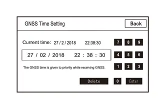
HINT:
When GNSS radio waves can be received, GNSS time is prioritized.
(1) When GNSS signals are not being received, the data and time in the device can be adjusted.
HINT:
For enter diagnostic mode and screen transition, refer to

CHECK Toyota Prius Vehicle SIGNAL
(a) Enter diagnostic mode.
(1) Enter diagnostic mode.
(2) Select "Function Check/Setting" from the "Service Menu" screen.
(3) Select "Vehicle Signal" on the "Function Check/Setting I" screen to display the Vehicle Signal Check Mode screen.
(b) Vehicle Signal Check Mode
(1) Check the Toyota Prius vehicle signal status stored in the radio and display receiver assembly.
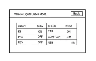 Screen Description
 | Display | Content | Signal Input Terminal |
|---|---|---|
| Battery | Auxiliary battery voltage is displayed. | Terminal B1 of the radio and display receiver assembly |
| IG | Ignition switch ON/OFF state is displayed. | Terminal IG of the radio and display receiver assembly |
| PKB | Parking brake ON/OFF state is displayed. | Terminal PKB of the radio and display receiver assembly |
| REV | Reverse signal ON/OFF state is displayed. | Terminal REV of the radio and display receiver assembly |
| SPEED | Toyota Prius Vehicle speed is displayed in km/h. | Terminal SPD of the radio and display receiver assembly |
| TAIL | Tail signal (light control switch) ON/OFF state is displayed. | Terminal ILL of the radio and display receiver assembly |
| ADIM/TCAN | Brightness state DIM (with) / BRIGHT (without) is displayed. | Input via CAN communication |
| USB | Displays the USB current (mA) | Terminal USV1 of the radio and display receiver assembly |
HINT:
- This screen is updated once per second.
- If Toyota Prius vehicle signals other than ADIM/TCAN are abnormal, inspect each terminal and wire harness.
-
If vehicle signal ADIM/TCAN is abnormal, it can be judged that the CAN communication system is malfunctioning.
Click here

HINT:
For enter diagnostic mode and screen transition, refer to

CHECK HANDS-FREE VOICE QUALITY AND VOLUME SETTING
(a) Enter diagnostic mode.
(1) Enter diagnostic mode.
(2) Select "Function Check/Setting" from the "Service Menu" screen.
(3) Select "HF Voice Quality Setting" on the "Function Check/Setting I" screen to display the "Hands-Free Voice Quality Setting" screen.
(b) Hands-Free Voice Quality Setting
Hands-Free Voice Quality Setting Screen Display Contents:
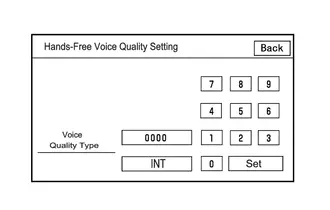
| Item | Display contents | Operation Procedure |
|---|---|---|
| Voice Quality Type | Adjusts the audio on the Toyota Prius vehicle side as heard by the other party | After setting the voice quality type using the numeric keypad, press the "Set" switch. |
NOTICE:
The input voice quality type number is valid if it is listed in the settings parameter tables. As there may be adverse effects after setting the voice quality type, make sure to confirm that there is no problem in the voice quality after changing the setting.
(1) If necessary, refer to the table below to adjust the voice quality type with the numeric keypad.
Settings| Parameter | Target Phenomenon | Voice Quality Type | Positive Effect of Changing Voice Quality | Negative Effect of Changing Voice Quality |
|---|---|---|---|---|
| B (Noise) | The other party hears background noise when listening to your voice. | 2000 | The amount of background noise the other party hears when listening to your voice is reduced. | Sound quality of the other party deteriorates. |
| D (Echo) | The other party hears strong echoes. | 0200 | The amount of echo is reduced. | The volume of voice the other party hears when listening to your voice may temporarily drop. |
| F (Sound Quality) | Sound quality of driver's voice, which the other party hears, is poor. | 0020 | Sound quality of driver's voice is improved. | The amount of background noise covering over the driver's voice is increased. |
| Parameter | Target Phenomenon | Voice Quality Type | Positive Effect of Changing Voice Quality | Negative Effect of Changing Voice Quality |
|---|---|---|---|---|
| B D | The other party hears a lot of background noise and strong echoes when listening to your voice. | 2200 |
|
|
| D F | The other party hears strong echoes and sound quality of driver's voice is poor. | 0220 |
|
|
HINT:
- The default value is "0000".
- Settings will be applied when the setting button is selected.
- If voice quality type values that are not in the table are input, the setting will not be applied and a positive effect may not be gained.
- If the quality of phone calls decreases due to the changed settings, return the settings to "0000" by selecting "INIT".
UPDATE VUI INFORMATION
HINT:
For enter diagnostic mode and screen transition, refer to Click here

(a) Enter diagnostic mode.
(1) Enter diagnostic mode.
(2) Select "Service Information" from the "Service Menu" screen.
(3) Select "VUI information" on the "Service Information" screen to display the "VUI information" screen.
(b) VUI Information
VUI Information Screen Display Contents| Display | Content | Remarks |
|---|---|---|
| *a: ECU | Displays the ECU ID name |
|
| *b: Table ID | Displays the Toyota Prius vehicle-specific number for the voice recognition commands. |
|
| *c: Table sub ID | Displays the latest version of voice recognition command IDs |
|
| *d: Update | Update the VUI information | - |
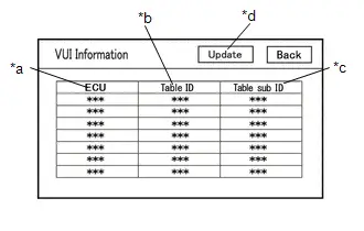
(1) If the table ID is "000", confirm that the CAN communication system is operating correctly and perform an inspection of the respective ECUs.
Click here

(2) If the table sub ID is "000", select "Update" on the VUI information screen and update VUI information.
ECU ID Display Content| ECU ID | ECU name |
|---|---|
| *: Perform the following procedure only for the above ECUs that are installed to the Toyota Prius vehicle | |
| 306 | Main Body ECU (Multiplex Network Body ECU) |
| 364 | Combination Meter Assembly |
| 28a | Forward recognition camera |
HINT:
For enter diagnostic mode and screen transition, refer to

CHECK "Bluetooth" CONNECTION HISTORY
(a) Connect the USB memory device to the No. 1 stereo jack adapter assembly.
(b) Enter diagnostic mode.
(1) Start diagnosis and display the "Service Menu" screen.

| *a | Green Indicator |
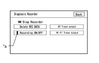
(2) Select "Failure Diagnosis" on the "Service Menu" screen to display the "Failure Diagnosis" screen.
(3) Select "Diagnosis Recorder" on the "Failure Diagnosis" screen to display the "Diagnosis Recorder" screen.
(4) Select "Recording ON/OFF" on the "Diagnosis Recorder" screen to turn off the indicator (green).
(5) Press and hold (for 3 seconds) "BT Trace output" on the "Diagnosis Recorder" screen.
HINT:
When the indicator (green) of "Recording ON/OFF" is illuminated, "BT Trace output" is grayed out and cannot be selected.
(c) BT Trace Output
(1) In accordance with the display, save the "Bluetooth" Connection History recorded data.
(2) Select "Recording ON/OFF" on the "Diagnosis Recorder" screen to turn on the indicator (green).
HINT:
- When performing the above procedure, make sure to set the indicator (green) of "Recording ON/OFF" back to the illuminated state.
-
The Bluetooth Connection History is stored in the ECU internal memory, and consists of timestamped operation data. By checking "Bluetooth" Connection History, the date, cause, etc. of a "Bluetooth" device failing to register or connect can be analyzed.
Click here

HINT:
For enter diagnostic mode and screen transition, refer to

CHECK "Wi-Fi" CONNECTION HISTORY
(a) Connect the USB memory device to the No. 1 stereo jack adapter assembly.
(b) Enter diagnostic mode.
(1) Enter diagnostic mode.
| *a | Green Indicator |
(2) Select "Failure Diagnosis" from the "Service Menu" screen.
(3) Select "Diagnosis Recorder" from the "Failure Diagnosis" screen.
(4) Select "Recording ON/OFF" on the "Diagnosis Recorder" screen and turn off the "Recording ON/OFF" green indicator.
(5) Select "Wi-Fi Trace output" for 3 seconds.
HINT:
When the green "Recording ON/OFF" indicator is illuminated, the "Wi-Fi" Trace output" is grayed out and cannot be selected.
(c) "Wi-Fi" Trace Output
(1) According to the instructions on the screen, save the "Wi-Fi" Connection History data to a USB memory device.
(2) Select "Recording ON/OFF" on the Diagnosis Recorder screen to illuminate the green "Recording ON/OFF" indicator.
HINT:
- Make sure that the green "Recording ON/OFF" indicator returns to illuminated state, after performing the above procedure.
-
This function is used to check the connection history when the connection between the radio and display receiver assembly and a "Wi-Fi" device is unstable.
Click here

CHECK NAVIGATION VOICE GUIDANCE SETTING (VOICE GUIDANCE NOT SOUNDING)
(a) Check settings
(1) Set the volume to maximum in the volume setting in the setting/edit screen (navigation) and check the speaking volume.
Standard:
Voice guidance can be heard.
HINT:
In the following situations, voice guidance is not performed even if the system is operating normally.- When a destination has not been set.
- When the Toyota Prius vehicle is not being driven on the specified route.
- When the guidance voice is muted.
CHECK GYRO INITIALIZATION (Vehicle position mark is rotating)
(a) Perform operation again
(1) Turn the ignition switch from off to ON, and check if the system returns to normal.
Standard:
The system returns to normal.
HINT:
- If the ignition switch is turned to ACC or ON while the Toyota Prius vehicle is being rotated (on a turntable, etc.), the system will display the vehicle position mark as rotating even when there is no malfunction as the radio and display receiver assembly will store the angular velocity as the reference value.
- In the above situation, turn the ignition switch from off to ACC with the Toyota Prius vehicle stopped to return the vehicle to normal.
Utility
UTILITY
SPEAKER LINE ELECTRICITY CHECK (w/ "JBL" Sound System)
HINT:
This function checks for an open in each speaker circuit.
(a) Speaker line electricity check
(1) In accordance with the display of the GTS, perform a speaker line electricity check.
Body Electrical > Navigation System > Utility| Tester Display |
|---|
| Speaker Line Electricity Check |
(2) If a speaker circuit malfunction is detected, perform troubleshooting for the output DTC.
Click here


SERVICE FLAG INFORMATION READING
HINT:
This function checks the service use conditions of the Toyota Prius vehicle.
(a) Check the service flag information.
(1) In accordance with the display of the GTS, display the service flag information screen.
Body Electrical > Navigation System > Utility| Tester Display |
|---|
| Service Flag Information Reading |
(2) Check the service flag information.
CONNECTION HISTORY INITIALIZATION
HINT:
This function initializes the connected device history.
(a) Connection history initialization
(1) In accordance with the display of the GTS, display the Initialize Connection History screen.
Body Electrical > Navigation System > Utility| Tester Display |
|---|
| Connection History Initialization |
(2) Perform connection history initialization.
MAP INFORMATION
HINT:
This function is used to check the map version of the navigation system and the end date of the map update service.
(a) Check map information.
(1) In accordance with the display of the GTS, display the "Map Information" screen.
Body Electrical > Navigation System > Utility| Tester Display |
|---|
| Map Information |
(2) Check the map version and the end date of the map update service.
NAVI SCREEN UNLOCK
HINT:
- This function can be used to release the security lock if the security lock password is forgotten.
- When releasing the security lock on the multi-display, you will be unable to enter a password if an incorrect password is entered a total of 20 times. The security lock will then need to be released using the GTS. (This can also be released by initializing the on-board device)
(a) Release the security lock using the GTS (Navi Screen Unlock)
(1) According to the display on the GTS, display the navi screen unlock screen.
Body Electrical > Navigation System > Utility| Tester Display |
|---|
| Navi Screen Unlock |
(2) According to the display on the GTS, release the security lock.
HINT:
- If authentication fails 100 times when using the GTS to release the security lock, the on-board device will be initialized.
- If the security lock is released using the GTS, the security lock setting of the on-board device will switch to "OFF" and the user set password will be cleared.
VIDEO DEVICE CONNECTION CHECK
HINT:
This function is used to detect disconnection of the video devices.
(a) Check Video Device Connection Check.
(1) In accordance with the display of the GTS, display the "Video Device Connection Check" screen.
Body Electrical > Navigation System > Utility| Tester Display |
|---|
| Video Device Connection Check |
(2) In accordance with the display of the GTS, perform the video device connection check.
Video Device Connection Check Screen Description| Error Detected Image Line (Type) | Areas to be Checked |
|---|---|
| H/U - > Separate Display (GVIF) | Not available |
| H/U - > Full RSE (GVIF) | Not available |
| RSE - > Seatback Display RH (GVIF) | Not available |
| RSE - > Seatback Display LH (GVIF) | Not available |
HINT:
- DTCs are stored when errors are detected.
- Depending on the Toyota Prius vehicle, some of the items will not be displayed on the "Error Detected Image Line (Type)" screen.
(b) Clear video device connection check.
(1) When DTCs are cleared using any of the following operations, Video Device Connection Check will be cleared as well.
Click here

- Cleared using the GTS.
- Cleared using the system check mode screen.
- Cleared using the unit check mode screen.
HINT:
- Whether the DTC judgement has completed can be checked using the GTS.
- This function can be used to confirm whether the DTC judgement has completed after a reproduction test for a DTC or after completing repairs.
ALL READINESS
(a) Using the GTS, clear the DTCs.
Even if no DTCs are stored, perform the Clear DTCs procedure as there may be pending DTCs.
Body Electrical > Navigation System > Clear DTCs(b) Turn the ignition switch off and wait for 120 seconds.
(c) Turn the ignition switch to ON and wait for 180 seconds.
(d) Perform the DTC judgement driving pattern to run the DTC judgement.
(e) Using the GTS, perform All Readiness.
Body Electrical > Navigation System > Utility| Tester Display |
|---|
| All Readiness |
(f) Proceed to the next screen and enter the DTC to be checked.
(g) Check the DTC judgment result.
| Result | Content |
|---|---|
| NORMAL |
|
| ABNORMAL |
|
| INCOMPLETE |
|
| N/A |
|
If the judgment result shows INCOMPLETE or N/A, perform the DTC judgement driving pattern and then recheck the judgment result.
(h) Turn the ignition switch off.
CHECK "Wi-Fi" CONNECTION HISTORY
HINT:
This function is used to check the connection history when the connection between the radio and display receiver assembly and a "Wi-Fi" device is unstable.
(a) Check "Wi-Fi" Connection History.
(1) Perform "Wi-Fi" Communication Trace output, and save the "Wi-Fi" Connection History data to a USB memory device.
Click here


(2) Connect the USB memory device with the saved "Wi-Fi" Connection History data to the GTS.
(3) Turn the GTS on.
(4) In accordance with screen on the GTS, select "Advanced Function" then "Wi-Fi" Connection History".
(5) According to the GTS screen, select the saved "Wi-Fi" Connection History file.
(6) When a value for an item is displayed in "Wi-Fi" Connection History, record it before proceeding with troubleshooting.
HINT:
When there is a "Wi-Fi" connection malfunction, refer to

| Item | Content | Note |
|---|---|---|
| Occurrence Date/Time | Year is displayed in 4 digits and month, date, hour, minute and second are displayed in 2 digits | - |
| Wi-Fi Setting State | OFF (Not Use Wi-Fi) | "Wi-Fi" function is off |
| ON (Use Wi-Fi) | "Wi-Fi" function is on | |
| Initial Activation | When the radio and display receiver starts up | |
| Contents | Connection | Result of Wi-Fi connection process |
| Auto Connection | Result of automatic Wi-Fi connection process (STA mode) | |
| Disconnection | Result of Wi-Fi disconnection process | |
| Mode Generation | Result of mode generation (ON) for STA, AP, and P2P | |
| Mode Destruction | Result of mode discard (OFF) for STA, AP, and P2P | |
| Initial Activation | When the radio and display receiver starts up | |
| Result | Connection Success | "Wi-Fi" successfully connected |
| Connection Failure (Time Out) | "Wi-Fi" could not be successfully connected | |
| Connection Failure (Authentication Failure) | "Wi-Fi" could not be successfully connected due to a verification error | |
| Connection Failure (Other Error) | "Wi-Fi" could not be successfully connected due to other error | |
| Disconnection Success | "Wi-Fi" successfully disconnected | |
| Disconnection Failure | "Wi-Fi" disconnection failed | |
| Action Mode | STA | STA (station) operating |
| AP | AP (access point) operating | |
| P2P | (P2P) operating | |
| Tip ID | Information indicating the chip during operation | |
| WLAN Standard | 802.11 B | Connected by 802.11b standard |
| 802.11 G | Connected by 802.11g standard | |
| 802.11 N | Connected by 802.11n standard | |
| 802.11 A | Connected by 802.11a standard | |
| 802.11 AC | Connected by 802.11ac standard | |
| Undetectable | Connected standard cannot be determined | |
| Channel Number | Displayed in decimal format with "Ch" | Number of the connected channels being used |
| Data Rate | Slow Speed | 1.0 Mbps - 24.0 Mbps |
| Medium Speed | 26.0 Mbps - 48.0 Mbps | |
| High Speed | 52.0 Mbps - 65.0 Mbps | |
| Received Signal Strength | -127dBm to 127dBm | Displays reception signal strength (weak, strong, etc. level value) |
| Packet Error Rate | Displayed in decimal format with "%" | Displays the ratio of packets not able to be received due to error |
| Destination MAC Address | Displayed in lower case hexadecimal format with "-" inserted every two characters | Name of connected MAC address |
| Destination SSID | Data is displayed as ASCII code | Name of connected SSID |
HINT:
If there is nothing to display in the "Content" column, "-" or "No Information" is displayed.
CHECK "Bluetooth" CONNECTION HISTORY
HINT:
- "Bluetooth" Connection History displays data stored in the internal memory of the ECU, such as the date a "Bluetooth" connection was attempted and the state of a "Bluetooth" connection. By checking "Bluetooth" Connection History, the date, cause, etc. of a "Bluetooth" device failing to register or connect can be analyzed.
- "Bluetooth" Connection History indicates the estimated cause of a malfunction, but does not determine it. Therefore, checking "Bluetooth" Connection History may not improve the problem.
(a) Check "Bluetooth" Connection History.
HINT:
Performing an inspection using the GTS before recording the "Bluetooth" Connection History may clear the history.
(1) Perform "BT Communication Trace output", and save the "Wi-Fi" Connection History data to a USB memory device.
Click here


(2) Connect the USB memory device with the saved "Bluetooth" Connection History data to the GTS.
(3) Turn the GTS on.
(4) In accordance with the screen on the GTS, select "Advanced Function" then "BT Connection History".
(5) According to the GTS screen, select the saved "Bluetooth" Connection History file to display the "Bluetooth" Connection History.
(6) When an item is stored for "Bluetooth" Connection History, record it before proceeding with troubleshooting.
HINT:
For troubleshooting "Bluetooth" connection malfunctions, refer to

| Item | Content | Note |
|---|---|---|
| Occurrence Date/Time | YYYY/MM/DD HH:MM:SS | Date and time of "Bluetooth" connection history recorded. |
| History Type | BT OFF | Type of "Bluetooth" Connection History is displayed. |
| Mobile Microwave Strength | ||
| BT Microwave Strength | ||
| Registration | ||
| Connection | ||
| Disconnection | ||
| Profile individual processing | ||
| BT ON | ||
| Device info | ||
| GNSS Reception | ||
| Record stop | ||
| Record start | ||
| Profile | HFP | Profile of "Bluetooth" Connection History is displayed. |
| PBAP | ||
| SPP | ||
| A2DP | ||
| AVRCP | ||
| MAP | ||
| Details of Profile | Depending on connection history type and profile, details are displayed | Refer to Details of Profile Display Contents table below |
| Result | Success | Result is displayed. |
| Failure | ||
| Contents | No Error | Contents of the Result is displayed. |
| Link Loss | ||
| Disconnection from Partner | ||
| Disconnection from Self | ||
| Time Out | ||
| Out of Service | ||
| Authentication Error | ||
| Page Time Out | ||
| Redial Regulation | ||
| Other Error | ||
| Bluetooth Address | Displays a hexadecimal number with upper-case characters | Address of the "Bluetooth" device is displayed. |
| Item | Content | Note |
|---|---|---|
| History Type value is "Mobile Microwave Strength" | Strength 0 | Cellular phone radio wave strength level is displayed |
| Strength 1 | ||
| Strength 2 | ||
| Strength 3 | ||
| Strength 4 | ||
| Strength 5 | ||
| History Type value is "BT Microwave Strength" | Deteriorate | "Bluetooth" radio wave reception level is displayed |
| Good | ||
| Profile value is "HFP" | Outbound Processing (Send from Self) | Details regarding HFP are displayed |
| Outbound Processing (Send from Partner) | ||
| Incoming Call Cancel (Cancel from Partner) | ||
| Incoming Call (Receive by Self) | ||
| Incoming Call (Receive by Partner) | ||
| Incoming Call (Block Incoming Call from Self) | ||
| Incoming Call (Block Incoming Call from Partner) | ||
| Incoming Call (Keep Response On Hold from Self) | ||
| Incoming Call (Block Incoming Call from Partner) | ||
| Call (Call from Self) | ||
| Call (Call from Partner) | ||
| Switching of The Call (Operate Self) | ||
| Switching of The Call (Operate Partner) | ||
| Switching of The Call (Partner Factor) | ||
| End of Call (End of Call from Self) | ||
| End of Call (End of Call from Intended Party) | ||
| Profile value is "PBAP" | Phone Book Transfer | Details regarding PBAP are displayed |
| Phone Book Stop Transfer | ||
| Profile value is "A2DP" | Streaming Play | Details regarding A2DP are displayed |
| Streaming Stop | ||
| Profile value is "AVRCP" | Play | Details regarding AVRCP are displayed |
| Stop | ||
| Pause | ||
| Truck Up | ||
| Track Down | ||
| Fast forward | ||
| Rewind | ||
| Repeat ON | ||
| Repeat OFF | ||
| Random ON | ||
| Random OFF | ||
| Acquisition of Music Information | ||
| Profile value is "MAP" | Message List Acquisition | Details regarding MAP are displayed |
| Message Acquisition | ||
| Setting of Notification Registration | ||
| Message Transmission |
HINT:
If there is nothing to display in the "Content" column, "-" or "No Information" is displayed.
Problem Symptoms Table
PROBLEM SYMPTOMS TABLE
HINT:
Depending on the multi-display settings, the background will remain started even when the ignitionswitch is turned off. For that reason, check the multi-display setting before performing an inspection.
Click here

| Symptom | Suspected Area | Link |
|---|---|---|
| Each time the ignition switch is turned to ON, the loading window is displayed. | Inspect the auxiliary battery. | - |
| Inspect the wire harness and connector (terminals B1 and ACC1 of the radio and display receiver assembly). |
| |
| Replace the radio and display receiver assembly. |
| |
| A message is displayed to inform the driver that the program cannot be read, and the system cannot be operated. | Replace the radio and display receiver assembly. |
|
| Toyota Prius Vehicle customization cannot be performed using the setting/editing display of the multi-display (customization is possible using the GTS). | Turn the ignition switch from off to ACC, then try again. | - |
| Replace the radio and display receiver assembly. |
|


- *1: w/ Intuitive Parking Assist System
- *2: w/ Panoramic View Monitor System
| Symptom | Suspected Area | Link |
|---|---|---|
| No image is displayed when the ignition switch is ACC (black screen). | If the screen is set to off, change the setting to on. | - |
| Replace the radio and display receiver assembly. |
| |
| White or blue screen is displayed when the ignition switch is turned to ACC. | Replace the radio and display receiver assembly. |
|
| Color distortion occurs in all of the displays. | Check the settings of the display quality adjustment screen (check that each setting is centered). | - |
| Replace the radio and display receiver assembly. |
| |
| The clearance sonar sensor display is not displayed.*1 | Check that the intuitive parking assist system is operating correctly. |
|
| The panoramic view monitor display is not displayed.*2 | Check that the panoramic view monitor system is operating correctly. |
|
| No air conditioning control screens are displayed. | Check that the air conditioning system is operating correctly. |
|


- *1: w/ Intuitive Parking Assist System
- *2: w/ Panoramic View Monitor System
| Symptom | Suspected Area | Link |
|---|---|---|
| When ASL (Auto Sound Levelizer) is operating and audio is being output, the sound volume does not change even when driving on a highway, etc. | Explain to the customer that if the sound volume is set to high, it is hard to notice the effect of ASL. | - |
| Check the settings of the sound quality adjustment screen (check that the ASL function is not set to off). | - | |
| Check the settings of the sound quality adjustment screen (check that each setting is centered). | - | |
| Proceed to "Check Toyota Prius Vehicle Signal" in Operation Check. (SPEED signal check) |
| |
| Inspect the wire harness and connector (radio and display receiver assembly (SPD) - combination meter assembly ( S) terminal). | - | |
| Proceed to the "Speed Signal Circuit" of the meter & gauge system. |
| |
| Replace the radio and display receiver assembly. |
| |
| In all modes, sound from all speakers cannot be heard, sound quality is poor in all modes (the displays and switch operations are correct) | Inspect the wire harness and connector (telematics transceiver (MUTE) - radio and display receiver assembly (TMUT) terminal).* | - |
| Inspect the telematics transceiver (MUTE) terminal.* |
| |
| Replace the radio and display receiver assembly. |
| |
| Sound from a specific speaker cannot be heard, sound quality is poor or sound is low in all modes | Check the settings of the sound quality adjustment screen (check that each setting is centered). | - |
| Check the settings of the sound quality adjustment screen (check that the ASL function on sound setting display 2 is set to off). | - | |
| Proceed to "Speaker Circuit" |
| |
| In all modes, noise occurs in all of the speakers. | Proceed to "In all Modes Noise Occurs in all of the Speakers" |
|


- *: w/Telematics Transceiver
| Symptom | Suspected Area | Link |
|---|---|---|
| When ASL (Auto Sound Levelizer) is operating and audio is being output, the sound volume does not change even when driving on a highway, etc. | Explain to the customer that if the sound volume is set to high, it is hard to notice the effect of ASL. | - |
| Check the settings of the sound quality adjustment screen (check that the ASL function is not set to off). | - | |
| Check the settings of the sound quality adjustment screen (check that each setting is centered). | - | |
| Proceed to "Check Toyota Prius Vehicle Signal" in Operation Check. (SPEED signal check) |
| |
| Inspect the wire harness and connector (stereo component amplifier assembly (SPD) - combination meter assembly ( S) terminal). | - | |
| Proceed to the "Toyota Prius Vehicle Speed Signal Circuit" of the meter & gauge system. |
| |
| Replace the stereo component amplifier assembly. |
| |
| Replace the radio and display receiver assembly. |
| |
| In all modes, sound from all speakers cannot be heard, sound quality is poor or sound is interrupted in all modes | Inspect wire harness and connectors [radio and display receiver assembly (MUT1) stereo component amplifier assembly (MUTE) terminal] | - |
| Inspect the stereo component amplifier assembly (MUTE) terminal. |
| |
| Inspect the wire harness and connector(radio and display receiver assembly(audio output) - stereo componentamplifier assembly (audio enter)terminal). | - | |
| Inspect the wire harness and connector (telematics transceiver (MUTE) - stereo component amplifier assembly (TMUT) terminal).*3 | - | |
| Inspect the telematics transceiver (MUTE) terminal.*3 |
| |
| Adjust the sound volume and if the value changes on the display, replace the stereo component amplifier assembly. |
| |
| Replace the radio and display receiver assembly. |
| |
| Sound from a specific speaker cannot be heard, sound quality is poor or sound is interrupted in all modes | Check the settings of the sound quality adjustment screen (check that each setting is centered). | - |
| Check the settings of the sound quality adjustment screen (check that the ASL function is set to off). | - | |
| Inspect the wire harness and connector (radio and display receiver assembly (audio output) - stereo component amplifier assembly (audio enter) terminal). | - | |
| Proceed to "Speaker Circuit Energization Inspection" in Utility. |
| |
| Replace the radio and display receiver assembly. | - | |
| In all modes, noise occurs in all of the speakers. | Proceed to "In all Modes Noise Occurs in all of the Speakers" |
|
| Voice recognition accuracy is low or there is an echo when using hands-free "Bluetooth" | Inspect the wire harness and connector (radio and display receiver assembly (FB1 , FB1-) - stereo component amplifier assembly (FB1 , FB1) terminal). | - |
| Inspect the wire harness and connector (radio and display receiver assembly (FB2 , FB2-) - stereo component amplifier assembly (FB2 , FB2-) terminal). | - | |
| Inspect the stereo component amplifier assembly (FBGN) terminal. |
| |
| Replace the stereo component amplifier assembly. |
| |
| Replace the radio and display receiver assembly. |
| |
| Voice guidance function does not operate | Check the settings of the sound quality adjustment screen (check that voice guidance is set to on). | - |
| Inspect the wire harness and connector (radio and display receiver assembly (RL , RL-) - stereo component amplifier assembly (II1 , II1-) terminal). | - | |
| Replace the stereo component amplifier assembly. |
| |
| Replace the radio and display receiver assembly. |
|


- *1: for 12.3 Inch Display
- *2: except 12.3 Inch Display
- *3: w/ Telematics Transceiver
| Symptom | Suspected Area | Link |
|---|---|---|
| Even though headlights are turned on, the display is not dimmed. | Check that the interior lighting system is operating correctly. |
|
| Proceed to "Even though Headlights are Turned on Head-unit does not Dim the Display" |
| |
| The night illumination function of the steering pad switch does not function (audio operation on the steering pad switch is normal). | Inspect the steering pad switch assembly (IL 2, ILL) terminal. |
|
| Inspect the spiral cable sub-assembly (IL 2) terminal. |
| |
| Inspect the wire harness and connector(spiral cable sub-assembly with sensor (IL 2) terminal). | - | |
| Inspect the wire harness and connector(spiral cable sub-assembly with sensor(ILL-) terminal). | - | |
| Replace combination meter assembly |
|


| Symptom | Suspected Area | Link |
|---|---|---|
| Touch switchoperation is notreceived. | Check that there is no foreign matter onthe screen and remove it if necessary | - |
| Function Check/Setting - Touch Switch Check |
| |
| Replace the radio and display receiver assembly. |
| |
| System does not respond to operation of the touch screen. | Check that there is no foreign matter caught, etc. in the switch for which the problem is occurring, and remove it if necessary. | - |
| Function inspection/calibration - panel &steering switch function |
| |
| Replace the radio and display receiver assembly. |
| |
| Audio system operation using the steering wheel switches does not function (sound output is normal and the operation of the panel switch is correct). | Check that there is no foreign matter caught, etc. in the switch for which the problem is occurring, and remove it if necessary. | - |
| Function inspection/calibration - panel &steering switch function |
| |
| Inspect the steering pad switch assembly (AU1, AU2, EAU) terminal. |
| |
| Inspect the spiral cable sub-assembly(AU1, AU2, EAU) terminal. |
| |
| Inspect the wire harness and connector(spiral cable sub-assembly - radio anddisplay receiver assembly terminal). | - | |
| Inspect the radio and display receiverassembly (SWG) terminal. |
| |
| Replace the radio and display receiver assembly. |
|


| Symptom | Suspected Area | Link |
|---|---|---|
| Toyota Prius Vehicle position mark deviates from correct position and does not return to correct position | Confirm again after removing all additional devices which use radio waves | - |
| Move the Toyota Prius vehicle (to a place where reception is good) | - | |
| Function inspection/calibration - navigation system inspection |
| |
| Inspect the navigation antenna assembly. |
| |
| Replace the antenna cord sub-assembly (for instrument panel). |
| |
| Replace the radio and display receiver assembly. |
| |
| Toyota Prius Vehicle position mark or map rotates randomly | Check that the gyro has been initialized (Explain to the customer that when the ignition switch is turned off and the vehicle is turned on a parking turntable, etc., the current vehicle position mark may not indicate the correct direction, however it returns to normal after driving the Toyota Prius vehicle for a while) | - |
| Replace the radio and display receiver assembly. |
| |
| Direction of travel and Toyota Prius vehicle position mark direction are opposite | Check after removing all additional devices which use radio waves. | - |
| Check that the gyro has been initialized (Explain to the customer that when the ignition switch is turned off and the Toyota Prius vehicle is turned on a parking turntable, etc., the current vehicle position mark may not indicate the correct direction, however it returns to normal after driving the vehicle for a while). | - | |
| Function inspection/calibration - Toyota Prius vehicle signal inspection (REV signal) |
| |
| Replace the radio and display receiver assembly. |
| |
| Toyota Prius Vehicle position mark moves ahead or falls behind, or deviates from and returns to correct position repeatedly. | Confirm after removing all additional devices which use radio waves. | - |
| Move the Toyota Prius vehicle (to a place where reception is good). | - | |
| Function inspection/calibration - navigation system inspection |
| |
| Perform sensor learning (at a place where GNSS signals can be received, drive the Toyota Prius vehicle clockwise and counterclockwise in at least a 200 meter square 2 times or more.) | - | |
| Function inspection/calibration - vehicle signal inspection (SPD signal) |
| |
| Inspect the wire harness and connector (radio and display receiver assembly (SPD) - combination meter assembly ( S) terminal). | - | |
| Proceed to the troubleshooting procedure of the meter & gauge system (Toyota Prius vehicle speed signal circuit) |
| |
| Inspect the navigation antenna assembly. |
| |
| Replace the antenna code sub-assembly. |
| |
| Replace the radio and display receiver assembly. |
| |
| Route voice guidance is not output or volume is low (audio guidance is normal) | Check that the audio function is operating correctly | - |
| Check the settings of the navigation voice guidance. |
| |
| Replace the radio and display receiver assembly. |
| |
| A message indicating to wait for a while because of low temperature is displayed. | Start the hybrid control system*1 or SFI system*2 and wait until the interior temperature increases. | - |
| Replace the radio and display receiver assembly. |
| |
| Subscription screen is visible instead of map display | Confirm that the communication is set to Wi-Fi and if operation is normal, inspect the telematics system |
|
| Check that the account is valid | - | |
| Turn the ignition switch off and try again | - | |
| Contact the support center | - | |
| No map download or update as the Toyota Prius vehicle moves | Confirm that the communication is set to Wi-Fi and if operation is normal, inspect the telematics system. |
|
| Confirm that the navigation screen can display a map with a distance of 100 miles from the current Toyota Prius vehicle location. | - | |
| Turn the ignition switch off and try again. | - | |
| Contact the support center. | - | |
| User profile and settings not available on head unit | Confirm that the communication is set to Wi-Fi and if operation is normal, inspect the telematics system. |
|
| Check that the account is valid | - | |
| Turn the ignition switch off and try again. | - | |
| Contact the support center. | - | |
| No destination results | Search using a different search method | - |
| Set the head unit to offline mode and search for a destination | - | |
| Turn the ignition switch off and try again. | - | |
| Contact the support center. | - | |
| Voice is not recognized for a navigation command | Check that the voice recognition system is functioning correctly. | - |
| Change the communication settings to Wi-Fi and if operation is normal, inspect the telematics system. |
| |
| Confirm that voice command setting is ON and the microphones are not blocked | - | |
| Check that the account is valid | - | |
| Turn the ignition switch off and try again. | - | |
| Contact the support center. | - | |
| Route cannot be calculated | Change the communication settings to Wi-Fi and if operation is normal, inspect the telematics system. |
|
| Set the head unit to offline mode | - | |
| Turn the ignition switch off and try again. | - | |
| Contact the support center. | - | |
| Alternate routes are not available | Change the communication settings to Wi-Fi and if operation is normal, inspect the telematics system. |
|
| Turn the ignition switch off and try again. | - | |
| Contact the support center. | - | |
| Voice Guidance does not function | Check voice guidance setting | - |
| Turn the ignition switch off and try again. | - | |
| Contact the support center. | - | |
| Traffic information is not available | Check navigation settings | - |
| Confirm that the communication is set to Wi-Fi and if operation is normal, inspect the telematics system. |
| |
| Turn the ignition switch off and try again. | - | |
| Confirm that the navigation screen can display a map with a distance of 100 miles from the current Toyota Prius vehicle location. | - | |
| Contact the support center. | - |


| Symptom | Suspected Area | Link |
|---|---|---|
| Radio broadcast cannot be received or poor reception. | Proceed to "Radio Broadcast cannot be Received or Poor Reception" |
|
| Radio broadcast can be received but radio station cannot be displayed. (Some radio stations do not provide their name information.) | Confirm that the communication is set to Wi-Fi and if operation is normal, inspect the telematics system. |
|
| Replace the radio and display receiver assembly. |
| |
| Radio broadcast can be displayed but radio broadcast cannot be heard from speakers. | Check the volume settings | - |
| Replace the radio and display receiver assembly. |
| |
| Radio broadcast can be received but station list cannot be displayed. | Wait for 120 seconds in radio mode, and select "Refresh" on the station list screen | - |
| Replace the radio and display receiver assembly. |
| |
| Radio broadcast can be received but station list cannot be updated. | Confirm that the communication is set to Wi-Fi and if operation is normal, inspect the telematics system. |
|
| Select "Refresh" on the station list screen | - | |
| Wait for 10 minutes with the ignition switch ON, and select "Refresh" on the station list screen again | - | |
| Replace the radio and display receiver assembly. |
|


| Symptom | Suspected Area | Link |
|---|---|---|
| Only "HD Radio" stations cannot be heard or selected, or their analog or digital sound cannot be changed. | Check the "HD Radio" settings | - |
| Radio and display receiver assembly |
| |
| When the HD radio is playing, cover art may not be displayed. | Check that the display cover art setting is not set to off. | - |
| When a song unregistered to the Gracenote CDDB is playing or cover art information is not provided by the broadcast station, its cover art cannot be displayed | - | |
| When the HD radio is playing, cover art cannot be displayed. | Check that the display cover art setting is not set to off. | - |
| Radio and display receiver assembly |
| |
| Broadcast station logo cannot be displayed. | Check if similar symptoms occur when receiving other broadcasts | - |
| Check if similar symptoms occur with another Toyota Prius vehicle | - | |
| Radio and display receiver assembly |
| |
| SPS channel cannot be selected. | Check that HD radio FM mode is selected | - |
| After pressing the "Refresh" switch, check that the SPS channel is on the station list | - | |
| Radio and display receiver assembly |
| |
| When the SPS channel is selected, sound cannot be heard. | After pressing the "Refresh" switch, select the SPS channel on the station list | - |
| Radio and display receiver assembly |
|


| Symptom | Suspected Area | Link |
|---|---|---|
| Satellite radio broadcast cannot be received or reception is bad. | Proceed to "Satellite Radio Broadcast cannot be Received" |
|
| Radio and display receiver assembly |
| |
| Satellite radio cannot receive pay-type broadcasts. | Proceed to "Satellite Radio Broadcast cannot be Received" |
|
| Radio and display receiver assembly |
| |
| Satellite radio broadcast cannot be selected or after selecting broadcast, broadcast cannot be added into memory. | Proceed to "Satellite Radio Broadcast cannot be Received" |
|
| Proceed to "Satellite Radio Broadcast cannot be Selected or After Selecting Broadcast, Broadcast cannot be Added into Memory" |
| |
| Radio and display receiver assembly |
| |
| Satellite radio can be displayed but radio broadcast cannot be heard from speakers. | Check the volume settings | - |
| Proceed to "Satellite Radio Broadcast cannot be Received" |
| |
| Radio and display receiver assembly |
| |
| When the satellite radio is playing, some cover art may not be displayed. | Check if similar symptoms occur when receiving conventional SiriusXM radio broadcasts. | - |
| When a song unregistered to the broadcast distribution is playing, its cover art cannot be displayed | - | |
| When the satellite radio is playing, cover art cannot be displayed. | Radio and display receiver assembly |
|
| After the voice recognition function or hands-free function is turned off, the cache radio does not operate | Radio and display receiver assembly |
|
| When the cache radio is playing, sound is interrupted, sound cannot be heard or sound quality is poor | Check if similar symptoms occur when receiving conventional SiriusXM radio broadcasts | - |
| Check if similar symptoms occur when receiving other broadcasts | - | |
| Move the Toyota Prius vehicle to a place where the reception is good and check again | - | |
| Radio and display receiver assembly |
| |
| When the cache radio is playing, sound can be heard, but no information is displayed (Some radio stations do not provide their name information) | Check if similar symptoms occur when receiving other broadcasts | - |
| Move the Toyota Prius vehicle to a place where the reception is good and check again | - | |
| Radio and display receiver assembly |
|


| Symptom | Suspected Area | Link |
|---|---|---|
| Cannot Establish Wi-Fi Connection* | Proceed to "Wi-Fi Connection History" |
|

- *: w/ Hotspot Function
| Symptom | Suspected Area | Link |
|---|---|---|
| Sound cannot be heard or sound quality is poor only when playing a USB storage device or "iPod". | Proceed to "Sound cannot be Heard Sound Quality is Poor only when Replaying USB Storage Device or "iPod"" |
|
| USB storage device or "iPod" cannot be detected or played. | Proceed to "USB Audio System Recognition/Play Error" |
|
| Track information such as track number, track name, elapsed time and playlist is not displayed. | Proceed to "USB Audio System Recognition/Play Error" |
|
| Although a USB storage device or "iPod" can be detected, the track cannot play, or can play but not in a sorted order. | Proceed to "USB Audio System Recognition/Play Error" |
|
| When "iPod" is replaying, cover art cannot be displayed. | Check that cover art settings are set to be displayed. | - |
| Replace the radio and display receiver assembly. |
| |
| When playing back from an "iPod", repeat cannot be turned off. | Check the device with which the malfunction occurs using another Toyota Prius vehicle of the same type. | - |
| Replace the radio and display receiver assembly. |
| |
| USB storage device or "iPod" cannot be charged. | Proceed to "USB Audio System Recognition/Play Error" |
|
| Screen is distorted or not displayed only when using the USB storage device. | Check using other media or check the media with which the malfunction occurs using another Toyota Prius vehicle of the same type. | - |
| Replace the No. 1 stereo jack adapter assembly. |
| |
| Replace the radio and display receiver assembly. |
| |
| The display color distortion occurs only when playing a USB storage device (normal for other types). | Check the settings of the display quality adjustment screen (check that each setting is centered). | - |
| Check using another device or check the device with which the malfunction occurs using another Toyota Prius vehicle of the same type. | - | |
| Replace the radio and display receiver assembly. |
| |
| "IF-BOX_USB" not displayed on the system check mode screen. | Proceed to "USB Audio System Recognition/Play Error" |
|


| Symptom | Suspected Area | Link |
|---|---|---|
| The energy flow display and the SOC (state of charge) level display is not displayed on the energy monitor display. | Turn the ignition switch to ON (READY), and check again. | - |
| Check that the hybrid control system is operating correctly. | - | |
| Replace the radio and display receiver assembly. |
| |
| The regenerated energy is not displayed on the trip information display. | Turn the ignition switch to ON (READY), and check again. | - |
| Check that the hybrid control system is operating correctly. | - | |
| Replace the radio and display receiver assembly. |
| |
| The trip information is not displayed or updated. | Turn the ignition switch to ON, and check again. | - |
| Check that the hybrid control system is operating correctly. | - | |
| Check that the electronically controlled brake system is operating correctly. |
| |
| Replace the radio and display receiver assembly. |
| |
| The drivable distance is not displayed on the trip information display. | Turn the ignition switch to ON, and check again. | - |
| Replace the radio and display receiver assembly. |
| |
| The fuel consumption history information is not displayed or updated. | Turn the ignition switch to ON, and check again. | - |
| Check that the meter and gauge system is operating correctly. |
| |
| Replace the radio and display receiver assembly. |
|


| Symptom | Suspected Area | Link |
|---|---|---|
| My Settings on the multi-display cannot be used | Proceed to "My Settings cannot be Used on the Multi-display" |
|

| Symptom | Suspected Area | Link |
|---|---|---|
| When the voice recognition switch of steering pad switch assembly is pressed, a short beep is not output and the voice recognition system does not start | Check that there is no foreign matter caught, etc. in the switch for which the problem is occurring, and remove it if necessary | - |
| Proceed to "Check Panel & Steering Switch" in Operation Check. |
| |
| Inspect the steering pad switch assembly. |
| |
| Inspect the spiral cable sub-assembly. |
| |
| Inspect the wire harness and connector (spiral cable sub-assembly - radio and display receiver assembly terminal). | - | |
| Replace the radio and display receiver assembly. |
| |
| Voice recognitiondoes not start even though wake word is spoken. | Check that the wake word in the settingsof the in-Toyota Prius vehicle device is not set to off. | - |
| Check that the wake word spoken by the user matches that in the settings of thein-vehicle device. | - | |
| If a custom wake word has been set inthe settings of the in-Toyota Prius vehicle device, try to set and check another wake word. (If wording is too long or too short, it maynot be recognized.) | - | |
| Proceed to "When voice recognition switch is pressed, a short beep is not emitted and the voice recognition system does notstart." |
| |
| Proceed to "Microphone Circuit" |
| |
| The voice recognition system starts but voice cannot be recognized properly. | Check that the Telematics system is operating correctly |
|
| Check that the microphone sound holes of the telephone microphone assembly are not blocked | - | |
| Confirm the installation condition of the telephone microphone assembly | - | |
| Proceed to "When Voice Recognition Switch is Pressed a Short Beep is Emitted but the Voice Recognition System does not Start" |
| |
| Proceed to "Microphone Circuit" |
| |
| Voicerecognition for Toyota Prius vehicle operations is not possible | Check that the Telematics system is operating correctly |
|
| Check service information (VUI) |
| |
| Replace the radio and display receiverassembly. |
|


| Symptom | Suspected Area | Link |
|---|---|---|
| "Bluetooth" is inoperative (in-Toyota Prius vehicle device cannot be recognized by the cellular phone) | Proceed to "Cellular Phone Inspection" |
|
| Replace the radio and display receiver assembly |
| |
| "Bluetooth" compatible cellular phone cannot be registered | Proceed to "Cellular Phone Registration Failure" |
|
| Proceed to ""Bluetooth" Connection History" |
| |
| "Bluetooth" compatible cellular phone cannot be connected | Check that another cellular phone is not already connected as a hands-free device | - |
| Bring the cellular phone near the in-Toyota Prius vehicle device and reconnect it | - | |
| Proceed to "Cellular Phone Inspection" |
| |
| Proceed to "'Bluetooth' Connection History" |
| |
| Replace the radio and display receiver assembly |
| |
| "Bluetooth" compatible cellular phone cannot be connected automatically (can be connected manually) | Check that the setting "Use for Phone" is set to on on the in-Toyota Prius vehicle device registration screen | - |
| Replace the radio and display receiver assembly |
| |
| 2 "Bluetooth" compatible cellular phones cannot connect at the same time | Check that the sign-in completes after opening the My Settings (user profile) screen | - |
| Check that another cellular phone is not already connected as a hands-free device | - | |
| Move the main cellular phone and sub-cellular phone close to the in-Toyota Prius vehicle device and connect again | - | |
| Proceed to "Cellular Phone Inspection" |
| |
| Proceed to "'Bluetooth' Connection History" |
| |
| Replace the radio and display receiver assembly |
| |
| Ringtone of a "Bluetooth" compatible cellular phone cannot be heard | Check that mute of the cellular phone is off | - |
| Adjust the sound volume of the cellular phone, and try again | - | |
| Proceed to "Cellular Phone Inspection" |
| |
| Replace the radio and display receiver assembly |
| |
| "Bluetooth" compatible cellular phone connection is disconnected | Bring the cellular phone near the in-Toyota Prius vehicle device and check if it is reconnected | - |
| Proceed to "Cellular Phone Inspection" |
| |
| Proceed to "'Bluetooth' Connection History" |
| |
| Replace the radio and display receiver assembly |
| |
| Bring the cellular phone near the in-Toyota Prius vehicle device and check if it is reconnected | Check that the sign-in completes after opening the My Settings (user profile) screen | - |
| Proceed to "Cellular Phone Registration Failure" |
| |
| Message that prompts to check the cellular phone is displayed | Bring the cellular phone near the in-Toyota Prius vehicle device and reconnect it | - |
| Proceed to "Cellular Phone Inspection" |
| |
| Replace the radio and display receiver assembly |
| |
| Phonebook data cannot be transferred | Check that the sync contact setting of the in-Toyota Prius vehicle device is on | - |
| Check that no application on a cellular phone is operating | - | |
| If using "Bluetooth" audio function, cancel the "Bluetooth" audio player connection and check the operation | - | |
| Turn the sync contact OFF and then turn ON | - | |
| Proceed to "Cellular Phone Inspection" |
| |
| Replace the radio and display receiver assembly |
| |
| Phonebook data is cleared | Check that the phonebook data automatic transfer has been completed | - |
| Replace the radio and display receiver assembly |
| |
| All the transferred phonebook data is sorted to "Other" | Check that no application on a cellular phone is operating | - |
| Check that phonebook data in the cellular phone is not stored to the SIM card | - | |
| Proceed to "Cellular Phone Inspection" |
| |
| Explain to the customer that all the transferred phonebook data may be stored to "Other" depending on cellular phone | - | |
| Cellular phone cannot make outgoing/incoming calls | Move the Toyota Prius vehicle into a cellular phone service area, check that the cellular phone is connected to the vehicle via "Bluetooth" and operate the in-vehicle device again | - |
| Check that the cellular phone can make outgoing/incoming calls properly when not connected via "Bluetooth" | - | |
| Check if a call confirmation message is displayed when attempting to call | - | |
| Proceed to "Cellular Phone Inspection" |
| |
| Proceed to ""Bluetooth" Connection History" |
| |
| Replace the radio and display receiver assembly |
| |
| Message cannot be viewed | Check that the cellular phone message forwarding setting is set to on | - |
| Proceed to "Cellular Phone Inspection" |
| |
| Replace the radio and display receiver assembly |
| |
| No notification when a message has arrived | Check that the application has not been left open on the cellular phone | - |
| Proceed to "Cellular Phone Inspection" |
| |
| Replace the radio and display receiver assembly |
| |
| Message cannot be sent | Proceed to "Cellular Phone Inspection" | - |
| Replace the radio and display receiver assembly |
| |
| Message synchronization cannot be set to off | Check if the cellular phone message forwarding is set off | - |
| Proceed to "Cellular Phone Inspection" |
| |
| Replace the radio and display receiver assembly |
| |
| Other caller's voice is interrupted by noise or sound quality is poor | Check the receiving voice volume (if it is too high, voice may sound distorted) | - |
| Proceed to "Hands-free Voice Quality and Volume Settings" in Operation Check. |
| |
| Make a call with the cellular phone disconnected from "Bluetooth" and check that other callers voice can be heard clearly | - | |
| Check that audio is correctly output for the radio | - | |
| Replace the radio and display receiver assembly |
| |
| Other caller's voice cannot be heard | Check that audio is correctly output for the radio | - |
| Make a call with the cellular phone disconnected from "Bluetooth" and check that other callers voice can be heard clearly | - | |
| Using the cellular phone setting display, confirm that the audio output device is registered to the in-Toyota Prius vehicle device. | - | |
| Check that reception voice volume is not set to minimum. | - | |
| Replace the radio and display receiver assembly |
| |
| Caller's voice (your voice) is interrupted by noise or sound quality is poor. | Check the transmitting voice volume (if it is too high, voice may sound distorted). | - |
| Proceed to "Hands-free Voice Quality and Volume Settings" in Operation Check. |
| |
| If any additional devices are installed, turn on/off the power switch and check whether noise occurs. | - | |
| Turn the ignition switch from ACC to off for a few times at a certain interval and check the sound volume of the calls. | - | |
| Using another cellular phone with another cellular phone carrier, check the sound volume of the calls a few times at a certain interval. | - | |
| Proceed to "When Voice Recognition Switch is Pressed a Short Beep is Emitted but the Voice Recognition System does not Start" |
| |
| Proceed to "Microphone Circuit" |
| |
| Other caller cannot hear your voice | When talking on the cellular phone, check that the mute button is not pressed. | - |
| Proceed to "When Voice Recognition Switch is Pressed a Short Beep is Emitted but the Voice Recognition System does not Start" |
| |
| Proceed to "Microphone Circuit" |
| |
| Sound output too low (other caller cannot hear your voice at an appropriate volume level) | Turn the ignition switch from ACC to off a few times at a certain interval and check the sound volume of the calls. | - |
| Using another cellular phone with another cellular phone carrier, check the sound volume of the calls a few times at a certain interval. | - | |
| Proceed to "When Voice Recognition Switch is Pressed a Short Beep is Emitted but the Voice Recognition System does not Start" |
| |
| Proceed to "Microphone Circuit" |
| |
| The telephone button on the steering pad switch cannot be operated but the displayed telephone button can be operated. | Check that there is no foreign matter caught, etc. in the switch for which the problem is occurring, and remove it if necessary | - |
| Check that the voice recognition switch on the steering pad switch can be operated. If it cannot be operated, proceed to "When voice recognition switch is pressed, a short beep is not emitted and the voice recognition system does not start" | - | |
| Inspect the steering pad switch assembly. |
|


| Symptom | Suspected Area | Link |
|---|---|---|
| "Bluetooth" portable audio player cannot be detected | Check if the portable audio player is not connected to the in-Toyota Prius vehicle device via "Apple CarPlay" or "Android Auto". | - |
| Confirm that the portable audio player is "Bluetooth" compatible. | - | |
| Check that the portable audio player is being connected to the in-Toyota Prius vehicle device via "Bluetooth" using the correct procedure. | - | |
| Check the portable audio player that the malfunction occurred for using another vehicle of the same type. | - | |
| Check after removing all additional devices which use radio waves. | - | |
| Replace the radio and display receiver assembly. |
| |
| Portable audio player cannot be connected manually/automatically. | Confirm that the portable audio player is "Bluetooth" compatible. | - |
| Check that the portable audio player is being connected to the in-Toyota Prius vehicle device via "Bluetooth" using the correct procedure. | - | |
| Check that the Bluetooth audio connection setting of the Bluetooth portable audio player is set to on. | - | |
| Select the customers portable audio player on the device registration screen of the in-Toyota Prius vehicle device and check that the "Use for Media" setting is set to on | - | |
| Check that the portable audio player is not in standby/sleep mode. | - | |
| Check that the portable audio player is not being connected to another device via "Bluetooth". | - | |
| Check the portable audio player that the malfunction occurred for using another Toyota Prius vehicle of the same type. | - | |
| Confirm after removing all additional devices which use radio waves. | - | |
| Replace the radio and display receiver assembly. |
| |
| Cellular phone with portable audio player function is connected via "Bluetooth" but cannot be detected as a "Bluetooth" compatible device. | Check if the portable audio player is not connected to the in-Toyota Prius vehicle device via "Apple CarPlay" or "Android Auto". | - |
| Confirm that the cellular phone with portable audio player function is "Bluetooth" compatible. | - | |
| Check that the cellular phone with portable audio player function is being connected to the in-Toyota Prius vehicle device via "Bluetooth" using the correct procedure | - | |
| Check the cellular phone with portable audio player function using another vehicle of the same type. | - | |
| Confirm after removing all additional devices which use radio waves. | - | |
| Replace the radio and display receiver assembly |
| |
| Portable audio player automatically starts. | Check that the cellular phone with portable audio player function is being connected to the in-Toyota Prius vehicle device via "Bluetooth" using the correct procedure. | - |
| Check that "Use for media" is set to off on the in-vehicle device | - | |
| Check the cellular phone with portable audio player function using another Toyota Prius vehicle of the same type. | - | |
| Sound from portable audio player cannot be heard, sound is low or sound quality is poor | Place the portable audio player to an appropriate position. | - |
| Check that the portable audio player is on and that the sound volume is not set to zero and mute is off | - | |
| Confirm that use of Wi-Fi connection is set to off. If Bluetooth and Wi-Fi devices are connected at the same time, depending on the specification of each device, one of them will be prioritized to output its audio. | - | |
| Check the portable audio player using another Toyota Prius vehicle of the same type. | - | |
| Replace the radio and display receiver assembly |
| |
| Sound from portable audio player is interrupted or noise occurs | Put the portable audio player in an appropriate location. | - |
| Confirm that Wi-Fi is set to off. If Bluetooth and Wi-Fi devices operate at the same time, the connection may be disconnected due to wave interference (the 2.4 GHz frequency band will be congested, etc.)). | - | |
| Check the portable audio player using another Toyota Prius vehicle of the same type. | - | |
| Confirm after removing all additional devices which use radio waves. | - | |
| Replace the radio and display receiver assembly. |
| |
| Portable player does not play even after "Bluetooth" audio mode is selected. | Check that the portable audio player is operating correctly. | - |
| Check the portable audio player using another Toyota Prius vehicle of the same type. | - | |
| Replace the radio and display receiver assembly. |
| |
| Track information such as track number, track name, elapsed play time and playlist is not displayed or the displayed contents is not correct. | Confirm that the cellular phone with portable audio player function is "Bluetooth" compatible. | - |
| Check that the track information is displayed on the portable audio player. | - | |
| Check the portable audio player using another Toyota Prius vehicle of the same type. | - | |
| Replace the radio and display receiver assembly. |
| |
| Operation switches for portable player such as play, pause, repeat are not displayed. | Check the portable audio player using another Toyota Prius vehicle of the same type. | - |
| Replace the radio and display receiver assembly. |
| |
| Portable player cannot pause, skip, fast forward, fast rewind, play at random, repeat | Check the portable audio player using another Toyota Prius vehicle of the same type. | - |
| Replace the radio and display receiver assembly. |
| |
| Registered device cannot be deleted. | Check that the portable audio player is being cleared from the in-Toyota Prius vehicle device using the correct procedure. | - |
| Replace the radio and display receiver assembly |
| |
| Track information is not listed or the displayed contents are not correct. | Check the portable audio player using another Toyota Prius vehicle of the same type. | - |
| Replace the radio and display receiver assembly. |
| |
| Repeat cannot be set to off | Check the device with which the malfunction occurs using another Toyota Prius vehicle of the same type. | - |
| Replace the radio and display receiver assembly. |
|


| Symptom | Suspected Area | Link |
|---|---|---|
| Apple CarPlay cannot be started by USB connection | Check that the customers device is compatible with Apple CarPlay | - |
| If a USB hub is being used, remove it | - | |
| Check the USB cable connection status and check that a genuine Apple USB cable or MFi certified USB cable is being used | - | |
| Check that the customers "Siri" function can be used on their device | - | |
| Select the customers device on the in-Toyota Prius vehicle device registration screen and check that the "Use for Apple CarPlay" setting is set to on | - | |
| Proceed to "Sound cannot be Heard Sound Quality is Poor only when Replaying USB Storage Device or "iPod"" |
| |
| Apple CarPlay cannot be started by wireless connection | Move the Toyota Prius vehicle to a place where there are minimal radio waves and Wi-Fi connection is possible, then check again | - |
| Access the official site (https://www.apple.com/) and search for "Apple CarPlay" in the search bar. Select iOS compatibility function and check that the customers device is listed | - | |
| Check that the version of the customers device is not earlier than iOS 13.3 | - | |
| Check that the customers device is being connected to the in-Toyota Prius vehicle device via "Bluetooth" using the correct procedure | - | |
| Check that the wireless connection setting of the customers device is set to on (permission) | - | |
| Check that the Apple CarPlay connection setting of the customers device is set to on (permission) | - | |
| Check that the "Bluetooth" connection setting of the customers device is set to on | - | |
| Check that the in-Toyota Prius vehicle device is displayed on the "Bluetooth" registered device screen of the customers device | - | |
| Check that the Wi-Fi connection setting of the customers device is set to on | - | |
| Check that [SSID: "Smartphone_Connect_######"] (where "######" is the last 6 digits of the Wi-Fi MAC address) is displayed as the connection information for the customers device | - | |
| Check that the name of the customers device is displayed as a "Bluetooth" registered device on the in-Toyota Prius vehicle device | - | |
| Select the customers device on the in-vehicle device registration screen and check that the "Use for Apple CarPlay" setting is set to on | - | |
| Select the customers device on the in-Toyota Prius vehicle device registration screen and check that Apple CarPlay starts when the "CONNECT" button is pressed | - | |
| Restart the customers device and check again | - | |
| Check if a "Bluetooth" connection can be established using another device | - | |
| Check that another device that is capable of tethering is displayed in "available networks" and check that a Wi-Fi connection can be established | - | |
| Replace the radio and display receiver assembly. |
| |
| Wireless connection disconnects unexpectedly | Move the Toyota Prius vehicle to a place where there are minimal radio waves and Wi-Fi connection is possible, then check again. | - |
| Check if "HotSpot" is set to off for the in-vehicle device | - | |
| Restart the customers device and check again. | - | |
| Check that another device that is capable of tethering is displayed in "available networks" and check that a Wi-Fi connection can be established. | - | |
| Replace the radio and display receiver assembly. |
| |
| When a wireless connection is established, Bluetooth Audio cannot be used at the same time | Check that a wireless connection and a Bluetooth Audio connection are not being attempted on the same device | - |
| Check that a connection can be established with another device and can be used at the same time | - | |
| Replace the radio and display receiver assembly. |
| |
| Even though "Hey Siri" is spoken, Siri does not start* | Check that the voice recognition function is operating correctly. | - |
| Check that the version of the customers device is not earlier than iOS 14.3 | - | |
| Check the value of the "Wake word" setting on the in-Toyota Prius vehicle device | - | |
| Check that "Wake word" is set to on in the settings of the in-vehicle device | - | |
| Check that the "Hey Siri" listening function is set to on (enabled) on the customers device | - | |
| Select the customers device on the in-Toyota Prius vehicle device registration screen and check that the "Use for Apple CarPlay" setting is set to on. | - | |
| Check if "HotSpot" is set to off for the in-vehicle device. | - | |
| Restart the customers device and check again. | - | |
| Replace the radio and display receiver assembly. |
| |
| Voice guidance and navigation information is not displayed on the combination meter assembly | Restart the customers device and check again. | - |
| Check that a different device can connect. | - | |
| Select the customers device on the in-Toyota Prius vehicle device registration screen and check that the "Use for Apple CarPlay" setting is set to on | - | |
| After clearing the registered device from the in-vehicle device, register the device again and check that it is displayed on the combination meter assembly | - | |
| Replace the radio and display receiver assembly. |
| |
| No audio when Apple CarPlay starts (Customers device is sufficiently charged) | Check that the audio function is operating correctly. | - |
| Check that sound can be heard from the device. | - | |
| Check that the sound volume is not set to zero. | - | |
| Check that the mute setting is set to off | - | |
| Replace the radio and display receiver assembly. |
|


- *: The availability of functions differs depending on the region and destination.
| Symptom | Suspected Area | Link |
|---|---|---|
| Android Auto cannot be started by USB connection | Check that the customers device is compatible with Android Auto | - |
| If a USB hub is being used, remove it | - | |
| Check that the cable connecting the customers device is a communication compatible cable HINT:
| - | |
| Check that Android Auto is installed on the customers device | - | |
| Select the customers device on the in-Toyota Prius vehicle device registration screen and check that the "Use for Android Auto" setting is set to on | - | |
| Proceed to "Sound cannot be Heard Sound Quality is Poor only when Replaying USB Storage Device or "iPod"" |
| |
| Android Auto cannot be started by wireless connection | Move the Toyota Prius vehicle to a place where there are minimal radio waves and Wi-Fi connection is possible, then check again | - |
| Access the official site (https://www.android.com/auto/) and check if the customers device is compatible | - | |
| Check that the customers device is being connected to the in-Toyota Prius vehicle device via "Bluetooth" using the correct procedure | - | |
| After confirming that the customers device has connected to Android Auto, check that "Rejected car" is not included on the in-vehicle device. | - | |
| Check that the "Bluetooth" connection setting of the customers device is set to on | - | |
| Check that the in-Toyota Prius vehicle device is displayed on the "Bluetooth" registered device screen of the customers device | - | |
| Check that the Wi-Fi connection setting of the customers device is set to on | - | |
| Check that [SSID: "Smartphone_Connect_######"] (where "######" is the last 6 digits of the Wi-Fi MAC address) is displayed as the connection information for the customers device | - | |
| Check that the name of the customers device is displayed as a "Bluetooth" registered device on the in-Toyota Prius vehicle device | - | |
| Select the customers device on the in-vehicle device registration screen and check that the "Use for Android Auto" setting is set to on | - | |
| Select the customers device on the in-Toyota Prius vehicle device registration screen and check that Android Auto starts when the "CONNECT" button is pressed | - | |
| Restart the customers device and check again | - | |
| Check if a "Bluetooth" connection can be established using another device | - | |
| Check that another device that is capable of tethering is displayed in "available networks" and check that a Wi-Fi connection can be established | - | |
| Replace the radio and display receiver assembly. |
| |
| Wireless connection disconnects unexpectedly | Move the Toyota Prius vehicle to a place where there are minimal radio waves and Wi-Fi connection is possible, then check again. | - |
| Check if "HotSpot" is set to off for the in-vehicle device. | - | |
| Restart the customers device and check again. | - | |
| Check that another device that is capable of tethering is displayed in "available networks" and check that a Wi-Fi connection can be established. | - | |
| Replace the radio and display receiver assembly. |
| |
| Call information is not displayed on the combination meter assembly. | Restart the customers device and check again. | - |
| Check that a different device can connect. | - | |
| Select the customers device on the in-Toyota Prius vehicle device registration screen and check that the "Use for Android Auto" setting is set to on. | - | |
| After clearing the registered device from the in-vehicle device, register the device again and check that it is displayed on the combination meter assembly. | - | |
| Replace the radio and display receiver assembly. |
| |
| No audio when Android Auto starts (Customers device is sufficiently charged) | Check that the audio function is operating correctly. | - |
| Check that sound can be heard from the device. | - | |
| Check that the sound volume is set to zero. | - | |
| Check that the mute setting is set to off. | - | |
| Replace the radio and display receiver assembly. |
|


| Symptom | Suspected Area | Link |
|---|---|---|
| Audio application is not displayed on sources list | Change the communication settings to Wi-Fi and if operation is normal, inspect the telematics system |
|
| Check operation of the server using another Toyota Prius vehicle | - | |
| Turn the ignition switch off and try again | - | |
| Initialize the in-vehicle device and check again | - | |
| Contact the support center | - | |
| Audio application did not load | Change the communication settings to Wi-Fi and if operation is normal, inspect the telematics system |
|
| Check operation of the server using another account or Toyota Prius vehicle | - | |
| Turn the ignition switch off and try again | - | |
| Initialize the in-vehicle device and check again | - | |
| Contact the support center | - | |
| Audio application not responsive | Change the communication settings to Wi-Fi and if operation is normal, inspect the telematics system |
|
| Check operation of the server using another Toyota Prius vehicle | - | |
| Turn the ignition switch off and try again | - | |
| Initialize the in-vehicle device and check again | - | |
| Contact the support center | - | |
| Audio application playing but no music heard | Check that mute of the audio is off | - |
| Check that the audio function is operating correctly. | - | |
| Issue TAS ticket (streaming audio does not produce sound, but other audio source has sound) | - |


| Symptom | Suspected Area | Link |
|---|---|---|
| "Sorry, there was a problem" message is displayed in navigation search (w/ Navigation Function) | Move the Toyota Prius vehicle (to a place where GNSS radio wave reception is good) | - |
| Change the communication settings to Wi-Fi and if operation is normal, inspect the telematics system. |
| |
| Turn the ignition switch off and try again. | - | |
| Contact the support center. | - | |
| "Sorry, there was a problem" message is displayed in media search | Move the Toyota Prius vehicle to a place where the reception sensitivity is good and check again | - |
| Confirm that the communication is set to Wi-Fi and if operation is normal, inspect the telematics system. |
| |
| Check using another audio player | - | |
| Turn the ignition switch off and try again. | - | |
| Contact the support center. | - | |
| "Sorry, there was a problem" message is displayed in phone search | Check that the cellular device is connected to the in-Toyota Prius vehicle device via "Bluetooth" | - |
| Verify contacts synced to head unit | - | |
| Turn the ignition switch off and try again. | - | |
| Contact the support center. | - | |
| "Sorry, there was a problem" message is displayed in setting search | Turn the ignition switch off and try again. | - |
| Contact the support center. | - | |
| Unable to enter keyboard search | Turn the ignition switch off and try again. | - |
| Contact the support center. | - |


| Symptom | Suspected Area | Link |
|---|---|---|
| Application does not operate normally | Confirm that the communication is set to Wi-Fi and if operation is normal, inspect the telematics system. |
|
| Check that the contract status of the service is valid and the user is signed in | - | |
| Turn the ignition switch off and try again. | - | |
| Check operation of the server using another account or Toyota Prius vehicle | - | |
| Check that the version of the application is the latest | - | |
| Initialize the in-vehicle device and check again | - | |
| Contact the support center. | - |

| Symptom | Suspected Area | Link |
|---|---|---|
| Destination assist call cannot be performed | Check that the Telematics system is operating correctly. |
|
| Check if the contract status of the service is valid. | - | |
| Contact the support center. | - |

Terminals Of Ecu
TERMINALS OF ECU
HINT:
Check from the rear of the connector while it is connected to the components.
RADIO AND DISPLAY RECEIVER ASSEMBLY
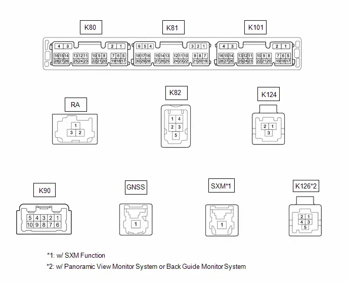 Connector K80
 | Terminal No. (Symbol) | Terminal Description | Condition | Specified Condition |
|---|---|---|---|
|
*1: w/ "JBL" Sound System
*2: w/ Panoramic View Monitor System | |||
| K80-1 (GND1) - Body ground | Ground | Always | Below 1 Ω |
| K80-2 (GND2) - Body ground | Ground | Always | Below 1 Ω |
| K80-3 ( B) - K80-1(GND1) | No.1 stereo jack adapter assembly power source | Ignition switch off | 11 to 14 V |
| K80-4 ( B1) - K80-1 (GND1) | Power source ( B) | Ignition switch off | 11 to 14 V |
| K80-5 (REV) - K80-1 (GND1) | Reverse Signal | Ignition switch ON, shift position not in R → shift position in R | 2 V or less → 11 to 14 V |
| K80-7 (PKB) - K80-1 (GND1) | Parking Brake Signal | Ignition switch ON Parking brake released → Ignition switch ON Parking brake applied | 0.4 V or less → 3 V or higher |
| K80-8 (SPD) - K80-1 (GND1) | Toyota Prius Vehicle speed signal | Wheel being rotated | Waveform 1 |
| K80-12 (MUT1) - K80-1 (GND1)*1 | Mute signal | Audio system playing → Mute | 3.5 V or higher → Below 1 V |
| K80-15 (IG) - K80-1 (GND1) | Power source (IG) | Ignition switch ON | 11 to 14 V |
| K80-16 (ACC1) - K80-1 (GND1) | Power source (ACC) | Ignition switch ACC | 11 to 14 V |
| K80-18 (CSWA) - K80-1 (GND1) | Camera image transition signal | Normal → camera image screen change | 2 V or less → 6 V or higher |
| K80-19 (CSW ) - K80-1 (GND1)*2 | Camera image transitionsignal | Normal → camera imagescreen change | 2 V or less → 6 V orhigher |
| K80-20 (SWG) - K80-1 (GND1) | Ground | Always | Below 1 Ω |
| K80-21 (SW1) - K80-1 (GND1) | Steering pad switch signal | No switch pushed → Volume- switch pushed → Volume switch pushed → Seek- switch pushed → Seek switch pushed | 2.7 V or higher → approximately 2.3 V → approximately 1.6 V → approximately 1.0 V → 0.8 V or less |
| K80-22 (SW2) - K80-1 (GND1) | Steering pad switch signal | No switch pushed → Voice switch pushed → Off hook switch pushed → On hook switch pushed → MODE switch pushed | 2.7 V or higher → approximately 2.3 V → approximately 1.6 V → approximately 1.0 V → 0.8 V or less |
| K80-24 (ILL-) - K80-1 (GND1) | Illumination signal ground | Dimmed | Pulse generation |
| K80-25 (ILL ) - K80-1 (GND1) | Illumination signal | Light control switch not in tail or head position | 11 to 14 V |
| K80-26 (WK2) - K80-1 (GND1)*1 | Stereo component amplifier assembly start up signal | Ignition switch ACC | 4 V or higher |
| K80-28 (ACCO) - K80-1 (GND1) | Multimedia ACC controlsignal | Power switch is pressed when playback is starting | 8.0 to 13.5 V |
| Terminal No. (Symbol) | Terminal Description | Condition | Specified Condition |
|---|---|---|---|
|
*1: w/ "JBL" Sound System
*2: w/ DCM (Telematics Transceiver) *3: w/Rear View Monitor System | |||
| K81-1 (TX1 )*1 | AVC-LAN communication signal | - | - |
| K81-2 (TX1-)*1 | AVC-LAN communication signal | - | - |
| K81-4 (SGND) - K80-1 (GND1) | Shield ground | Always | Below 1 Ω |
| K81-5 (TMUT) - K80-1 (GND1)*2 | Mute signal | Normal → Emergency call mode | 2.0 V or higher → Below 1 V |
| K81-6 (ADPG) - K80-1 (GND1) | No. 1 stereo jack adapterassembly detection signal | No. 1 stereo jack adapterassembly disconnected →No. 1 stereo jack adapterassembly connected | Below3.2 V |
| K81-11 (CNH1) | Local bus communication signal | Service Menu | - |
| K81-12 (CNL1) | Local bus communication signal | Service Menu | - |
| K81-13 (CANH) | CAN communication signal | Service Menu | - |
| K81-14 (CANL) | CAN communication signal | Service Menu | - |
| K81-15 (VOR )*2 | Sound signal | Answering incomingoperator call | A waveform synchronizedwith sound signals isoutput |
| K81-16 (VOR-)*2 | Sound signal | Answering incomingoperator call | A waveform synchronizedwith sound signals isoutput |
| K81-17 (USBG) - Body ground*2 | Ground | Always | Below 1 Ω |
| K81-18 (USBV) - K80-1 (GND1)*2 | Telematics transceiver USB power source | Ignition switch ON | 3 V or higher |
| K81-21 (MIN ) - K80-1 (GND1) | Microphone voice signal | Voice is being input | A waveform synchronized with sound signals is output |
| K81-22 (MIN-) - K80-1 (GND1) | Microphone voice signal ground | Always | Below 1 Ω |
| K81-23 (MACC) - K80-1 (GND1) | Microphone power source | Ignition switch ON | 7.5 to 8.5 V |
| K81-24 (SGND) - Body ground | Shield ground | Always | Below 1 Ω |
| K81-25 (SNS) - K80-1 (GND1) | Microphone circuit open detection signal | Always | Below 1 Ω |
| K81-26 (CSLD) - K80-1 (GND1)*3 | Shield ground | Always | Below 1 Ω |
| K81-27 (CGND) - K80-1 (GND1)*3 | Camera Ground | Always | Below 1 Ω |
| K81-28 (V ) - K81-29 (V-)*3 | Video Signal | Ignition switch ON, shift position in R | - |
| K81-29 (V-) - K80-1 (GND1)*3 | Video Signal | Always | Below 1 Ω |
| K81-30 (CA ) - K80-1 (GND1)*3 | Camera power source | Ignition switch ON | 7.5 to 9.0 V |
| Terminal No. (Symbol) | Terminal Description | Condition | Specified Condition |
|---|---|---|---|
| *: w/ "JBL" Sound System | |||
| K101-4 (FBGN) - K80-1 (GND1)* | Shield ground | Always | Below 1 Ω |
| K101-15 (FB2 ) - K80-1 (GND1)* | Stereo component amplifier assembly voice signal 2 | Voice is being input | A waveform synchronized with sound signals is output |
| K101-16 (FB2-) - K80-1 (GND1)* | Stereo component amplifier assembly voice signal 2 | Voice is being input | A waveform synchronized with sound signals is output |
| K101-17 (MI2 ) - K80-1 (GND1) | Microphone 2 voice signal | Voice is being input | A waveform synchronizedwith sound signals isoutput |
| K101-18 (MI2-) - K80-1 (GND1) | Microphone 2 voice signal ground | Always | Below 1 Ω |
| K101-19 (SGD2) - K80-1 (GND1) | Ground | Always | Below 1 Ω |
| K101-20 (MAC2) - K80-1 (GND1) | Microphone 2 powersource | Ignition switch ON | 7.5 to 8.5 V |
| K101-21 (SNS2) - K80-1 (GND1) | Microphone 2 open circuitdetection signal | Always | Below 1 Ω |
| K101-27 (FB1 ) - K80-1 (GND1)* | Stereo component amplifier assembly voice signal 1 | Voice is being input | A waveform synchronized with sound signals is output |
| K101-28 (FB1-) - K80-1 (GND1)* | Stereo component amplifier assembly voice signal 1 | Voice is being input | A waveform synchronized with sound signals is output |
| Terminal No. (Symbol) | Terminal Description | Condition | Specified Condition |
|---|---|---|---|
|
*1: w/o "JBL" Sound System
*2: w/ "JBL" Sound System | |||
| K90-1 (FR ) - K80-1 (GND1) | Sound signal | Audio system playing | A waveform synchronized with sound signals is output |
| K90-2 (FL ) - K80-1 (GND1) | Sound signal | Audio system playing | A waveform synchronized with sound signals is output |
| K90-3 (RL ) - K80-1 (GND1) | Sound signal*1 Interrupt sound signal*2 | Audio system playing*1 Interrupt sound signal being output*2 | A waveform synchronized with sound signals is output |
| K90-4 (RR ) - K80-1 (GND1) | Sound signal*1 Interrupt sound signal*2 | Audio system playing*1 Interrupt sound signal being output*2 | A waveform synchronized with sound signals is output |
| K90-6 (FR-) - K80-1 (GND1) | Sound signal | Audio system playing | A waveform synchronized with sound signals is output |
| K90-7 (FL-) - K80-1 (GND1) | Sound signal | Audio system playing | A waveform synchronized with sound signals is output |
| K90-8 (RL-) - K80-1 (GND1) | Sound signal*1 Interrupt sound signal*2 | Audio system playing*1 Interrupt sound signal being output*2 | A waveform synchronized with sound signals is output |
| K90-9 (RR-) - K80-1 (GND1) | Sound signal*1 Interrupt sound signal*2 | Audio system playing*1 Interrupt sound signal being output*2 | A waveform synchronized with sound signals is output |
| Terminal No. (Symbol) | Terminal Description | Condition | Specified Condition |
|---|---|---|---|
| K124-1 (USB ) | USB signal | - | - |
| K124-2 (USB-) | USB signal | - | - |
| K124-3 (USBS) | Shield ground | Always | Below 1 Ω |
| Terminal No. (Symbol) | Terminal Description | Condition | Specified Condition |
|---|---|---|---|
| K82-1 (USV1) | Power source | Ignition switch ON | 4.75 to 5.25 V |
| K82-2 (US1-) | USB communication signal | - | - |
| K82-3 (US1 ) | USB communication signal | - | - |
| K82-4 (UGD1) | Ground | Always | Below 1 Ω |
| K82-5 (USG1) | Shield ground | Always | Below 1 Ω |
| Terminal No. (Symbol) | Terminal Description | Condition | Specified Condition |
|---|---|---|---|
| RA-1 (ANT ) | Radio antenna power source | Receiving radio broadcast | 7 to 16 V |
| RA-2a (GND) | Ground | - | - |
| RA-3 (MAIN) | Radio signal | - | - |
| RA-3a (GND) | Ground | - | - |
| Terminal No. (Symbol) | Terminal Description | Condition | Specified Condition |
|---|---|---|---|
| GNSS-1 (GPS) | GNSS signal | - | - |
| Terminal No. (Symbol) | Terminal Description | Condition | Specified Condition |
|---|---|---|---|
| SXM-1(XM) | SXM Radio Signal | - | - |
| Terminal No. (Symbol) | Terminal Description | Condition | Specified Condition |
|---|---|---|---|
| K126-1(GGND) | Camera ground | Always | Below 1 Ω |
| K126-2(GB ) | Camera power source | Ignition switch ON | 7.5 to 9.0 V |
| K126-3(GVO ) | Video signal | - | - |
| K126-4(GVO-) | Video signal | - | - |
| K126-5(SGND) | Shield ground | Always | Below 1 Ω |
| Terminal No. (Symbol) | Terminal Description | Condition | Specified Condition |
|---|---|---|---|
| K126-1(CGND) | Camera ground | Always | Below 1 Ω |
| K126-2(CB ) | Camera power source | Ignition switch ON | 7.5 to 9.0 V |
| K126-3(CV ) | Video signal | - | - |
| K126-4(CV-) | Video signal | - | - |
| K126-5(SGND) | Shield ground | Always | Below 1 Ω |
(a) Waveform 1

| Item | Content |
|---|---|
| Measurement terminal | K80-8 (SPD) - K80-1 (GND1) |
| Measurement setting | 5 V/DIV., 20 ms/DIV |
| Condition | Wheel being rotated |
HINT:
The period changes depending on the rotation speed of the wheels.
(b) Reference (Oscilloscope waveform):
(1) Waveform 1 (camera lens not covered, displaying an image)
| Item | Content |
|---|---|
| Measurement terminal | K81-28 (V ) - K81-29 (V-) |
| Measurement setting | 200 mV/DIV., 50 μs/DIV. |
| Condition | Ignition switch ON, shift lever in R |
HINT:
- The video waveform changes according to the image sent by the rear television camera assembly.
- The video waveform is constantly output when the ignition switch ACC.
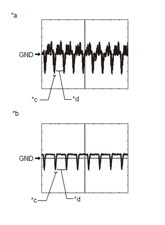
| *a | Waveform 1 (camera lens not covered, displaying an image) |
| *b | Waveform 2 (camera lens covered, blacking out the screen) |
| *c | Synchronization Signal |
| *d | Video Waveform |
(2) Waveform 2 (camera lens covered, blacking out the screen)
| Item | Content |
|---|---|
| Measurement terminal | K81-28 (V ) - K81-29 (V-) |
| Measurement setting | 200 mV/DIV., 50 μs/DIV. |
| Condition | Ignition switch ON, shift lever in R |
HINT:
- The video waveform changes according to the image sent by the rear television camera assembly.
- The video waveform is constantly output when the ignition switch ACC.
STEREO COMPONENT AMPLIFIER ASSEMBLY (w/ "JBL" Sound System)
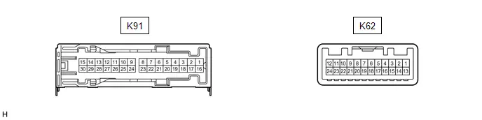 Connector K91
 | Terminal No. (Symbol) | Terminal Description | Condition | Specified Condition |
|---|---|---|---|
| K91-1 ( B) - K91-3 (GND) | Power source ( B) | Ignition switch off | 11 to 14 V |
| K91-3 (GND) - Body ground | Ground | Always | Below 1 Ω |
| K91-8 (WFL ) - K91-3 (GND) | Sound signal (Woofer) | Audio system playing | A waveform synchronized with sound signals is output |
| K91-9 (TWL ) - K91-3 (GND) | Rear sound signal (LH) | Audio system playing | A waveform synchronized with sound signals is output |
| K91-10 (WFR ) - K91-3 (GND) | Sound signal (Woofer) | Audio system playing | A waveform synchronized with sound signals is output |
| K91-11 (TWR ) - K91-3 (GND) | Rear sound signal (RH) | Audio system playing | A waveform synchronized with sound signals is output |
| K91-12 (FL ) - K91-3 (GND) | Front sound signal (LH) | Audio system playing | A waveform synchronized with sound signals is output |
| K91-13 (RL ) - K91-3 (GND) | Front sound signal (LH) | Audio system playing | A waveform synchronized with sound signals is output |
| K91-14 (FR ) - K91-3 (GND) | Front sound signal (RH) | Audio system playing | A waveform synchronized with sound signals is output |
| K91-15 (RR ) - K91-3 (GND) | Front sound signal (RH) | Audio system playing | A waveform synchronized with sound signals is output |
| K91-16 ( B2) - K91-3 (GND) | Power source ( B) | Ignition switch off | 11 to 14 V |
| K91-18 (GND2) - Body ground | Ground | Always | Below 1 Ω |
| K91-23 (WFL-) - K91-3 (GND) | Sound signal (Woofer) | Audio system playing | A waveform synchronized with sound signals is output |
| K91-24 (TWL-) - K91-3 (GND) | Rear sound signal (LH) | Audio system playing | A waveform synchronized with sound signals is output |
| K91-25 (WFR-) - K91-3 (GND) | Sound signal (Woofer) | Audio system playing | A waveform synchronized with sound signals is output |
| K91-26 (TWR-) - K91-3 (GND) | Rear sound signal (RH) | Audio system playing | A waveform synchronized with sound signals is output |
| K91-27 (FL-) - K91-3 (GND) | Front sound signal (LH) | Audio system playing | A waveform synchronized with sound signals is output |
| K91-28 (RL-) - K91-3 (GND) | Front sound signal (LH) | Audio system playing | A waveform synchronized with sound signals is output |
| K91-29 (FR-) - K91-3 (GND) | Front sound signal (RH) | Audio system playing | A waveform synchronized with sound signals is output |
| K91-30 (RR-) - K91-3 (GND) | Front sound signal (RH) | Audio system playing | A waveform synchronized with sound signals is output |
| Terminal No. (Symbol) | Terminal Description | Condition | Specified Condition |
|---|---|---|---|
| K62-1 (MUTE) - K91-3 (GND) | Mute signal | Normal → Mute | 3.5 V or higher → Below 1 V |
| K62-2 (L-) - K91-3 (GND) | Input voice signal (LH) | Voice is being input | A waveform synchronized with sound signals is output |
| K62-3 (L ) - K91-3 (GND) | Input voice signal (LH) | Voice is being input | A waveform synchronized with sound signals is output |
| K62-4 (R-) - K91-3 (GND) | Input voice signal (RH) | Voice is being input | A waveform synchronized with sound signals is output |
| K62-5 (R ) - K91-3 (GND) | Input voice signal (RH) | Voice is being input | A waveform synchronized with sound signals is output |
| K62-6 (SLD) - Body ground | Shield ground | Always | Below 1 Ω |
| K62-7 (TX-) | AVC-LAN communication signal | Service Menu | - |
| K62-8 (TX ) | AVC-LAN communication signal | Service Menu | - |
| K62-9 (FB1-) - K91-3 (GND) | Sound signal | Audio system playing | A waveform synchronized with sound signals is output |
| K62-10 (FB1 ) - K91-3 (GND) | Sound signal | Audio system playing | A waveform synchronized with sound signals is output |
| K62-11 (SPD) - K91-3 (GND) | Toyota Prius Vehicle speed signal | Wheel being rotated | Waveform 1 |
| K62-12 (WK2) - K91-3 (GND) | Stereo component amplifier assembly start signal | Ignition switch ACC | 4 V or higher |
| K62-13 (SLD1) - Body ground | Ground | Always | Below 1 Ω |
| K62-14 (ll1-) - K91-3 (GND) | Input voice signal (LH) | Interrupt voice is being input | A waveform synchronized with sound signals is output |
| K62-15 (ll1 ) - K91-3 (GND) | Input voice signal (LH) | Interrupt voice is being input | A waveform synchronized with sound signals is output |
| K62-16 (ll2-) - K91-3 (GND) | Input voice signal (RH) | Interrupt voice is being input | A waveform synchronized with sound signals is output |
| K62-17 (ll2 ) - K91-3 (GND) | Input voice signal (RH) | Interrupt voice is being input | A waveform synchronized with sound signals is output |
| K62-18 (SLD2) - Body ground | Shield ground | Always | Below 1 Ω |
| K62-21 (FB2-) - K91-3 (GND) | Sound signal | Audio system playing | A waveform synchronized with sound signals is output |
| K62-22 (FB2 ) - K91-3 (GND) | Sound signal | Audio system playing | A waveform synchronized with sound signals is output |
| K62-24 (TMUT) - K91-3 (GND) | Mute signal | Normal → Mute | 3.5 V or higher → Below 1 V |
(a) Waveform 1
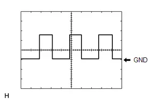
| Item | Content |
|---|---|
| Measurement terminal | K62-11 (SPD) - K91-3 (GND) |
| Measurement setting | 5 V/DIV., 20 ms/DIV. |
| Condition | Wheel being rotated |
HINT:
The period changes depending on the rotation speed of the wheels.
DCM (TELEMATICS TRANSCEIVER)
Click here

COMBINATION METER ASSEMBLY
HINT:
Click here

REAR TELEVISION CAMERA ASSEMBLY (w/ Back Guide Monitor System or Rear Television Camera)
HINT:
Click here

PARKING ASSIST ECU (w/ Panoramic View Monitor System)
HINT:
Click here

Diagnosis System
DIAGNOSIS SYSTEM
HINT:
- When system self-diagnosis DTCs cannot be output due to a malfunction that is preventing diagnosis mode from being started or the multi-display from displaying, read the DTCs using the GTS.
-
Depending on the multi-display settings, the background will remain started even when the ignition switch is turned off. For that reason, check the multi-display setting before performing an inspection.
Click here

CHECK FOR DTCs (USING SYSTEM CHECK MODE SCREEN)
(a) Start diagnosis and display the "Service Menu" screen.
(b) Select "Failure Diagnosis" on the service menu screen to display the failure diagnosis screen.
(c) Select "System Check" of the failure diagnosis screen to display the system check mode screen.
System Check Mode Screen Description| Display | Content |
|---|---|
| *a: Device Name List | Displays the components names, including additional devices (the physical address is displayed if the name is unknown) |
| *b: Check Result | Displays the inspection result of connected devices |
| *c: Optional Device Name List | Displays the components names, including aftermarket devices |
| *d: Memory Clear | Clear current DTCs and confirmed DTCs (press and hold for 3 seconds or more) |
| *e: Recheck | Performs a check again |
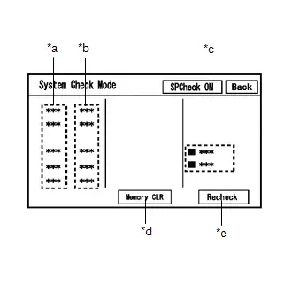
(1) Confirm that each of the following connected devices are displayed:
| Name | Component | Connection Method |
|---|---|---|
| AVN | Radio and display receiver assembly | - |
| DSP-AMP | Stereo componentamplifier assembly* | AVC-LAN |
| IF-BOX_USB | No. 1 stereo jack adapter assembly | USB |
| DCM | DCM (telematics transceiver) | USB |
- *: w/ "JBL" Sound System
HINT:
- When diagnosis starts, the system check mode screen is displayed and the check is performed.
- System check mode displays the inspection results screen based on the response for each device during "system inspection instruction", "system inspection result demand", etc., and "Normal Diagnosis Notice", notifications.
- The displayed screen is an example only. The actual device name displayed on the screen may differ depending on the connected device (dealer installed options, etc.).
(2) CHECK SYSTEM CHECK RESULTS (AVC-LAN/USB/LOCAL BUS CONNECTED DEVICES)
| Check result | Meaning |
|---|---|
|
*1: When the "DETAIL" button is pressed, the system transitions to the unit check mode screen.
*2: If "NCON" is displayed for all AVC-LAN connected devices or all AVC-LAND connected devices are not displayed, refer to the troubleshooting procedure for AVC-LAN malfunction. Click here
| |
| OK | No DTCs are stored |
| DETAIL (*1) | DTCs are stored |
| NCON (*2) |
|
| NRES | No response of diagnosis information |
| Device name and/or system check result cannot be displayed for AVC-LAN*2/USB/LOCAL BUS CONNECTED DEVICES | No history of a device being registered to the system, and no response during the diagnosis check |

(d) Unit Check Mode
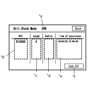
(1) When "DETAIL" is displayed on the system check mode inspection results, the system transitions to the unit check mode screen when pressed.
(2) Confirm and record the DTCs
Unit Check Mode Screen Description| Display | Content |
|---|---|
| *a: Device name | Target device name |
| *b: History DTC | Displays stored DTCs (up to 6 items) for the target device |
| *c: Latest | An "X" is displayed for the target device when latest DTCs (latest malfunction in current trip) exist |
| *d: Confirm | An "X" is displayed for the target device when confirmed DTCs (diagnostic trouble codes that have been confirmed up until the current time) exist |
| *e: Time of occurrence | Displays the time that the DTC was stored |
| *f: Code CLR | Clears DTC information of the target device and clears the display |
NOTICE:
A maximum of 6 codes are stored for the radio and display receiver assembly. When it is suspected that more than 6 codes are output, confirm the DTCs using the GTS.
HINT:
Unit check mode screen is updated once per second.
CLEAR DTC (USING SYSTEM CHECK MODE SCREEN)
(a) Clear the DTCs
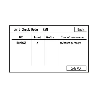
(1) Select "Code CLR" on the unit check mode screen (press and hold for 3 seconds or more) and clear the DTCs.
ENTER DIAGNOSTIC MODE
HINT:
- When system self-diagnosis DTCs cannot be output due to a malfunction that is preventing diagnosis mode from being started or the multi-display from displaying, read the DTCs using the GTS.
- Enter diagnostic mode by performing one of the following methods.
(a) Start method 1
(1) Using the GTS, display the diagnostic mode window.
Body Electrical > Navigation System > Utility| Tester Display |
|---|
| Diagnostic Mode |
(2) When diagnosis starts, the "Service Menu" screen is displayed.
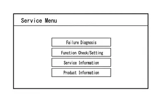
(b) Start method 2
(1) Ensure that the Toyota Prius vehicle is stopped.
(2) Turn the ignition switch to ON.
(3) Turn off the multi-display.
(4) Turn off the audio of the radio and display receiver assembly.
(5) Flick the multi-display 5 times from left to right as shown in the illustration.
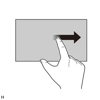
(6) Flick the multi-display 5 times from right to left as shown in the illustration.
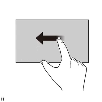
HINT:
Make sure to complete the operation within 15 seconds of performing the initial flick from left to right.
(7) When diagnosis starts, the service menu screen is displayed.
HINT:
If diagnosis does not start due to a failed operation, turn the display on then off and perform the procedure from the start. (Only turning the audio of the radio and display receiver assembly from off to on is not a valid method)

DIAGNOSTIC MODE SCREEN TRANSITION
(a) Service Menu
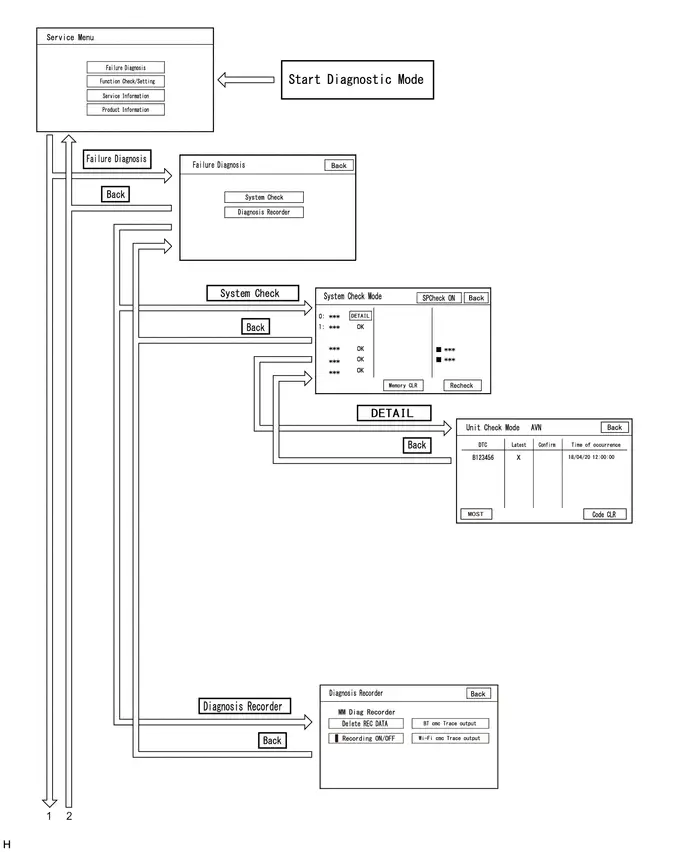
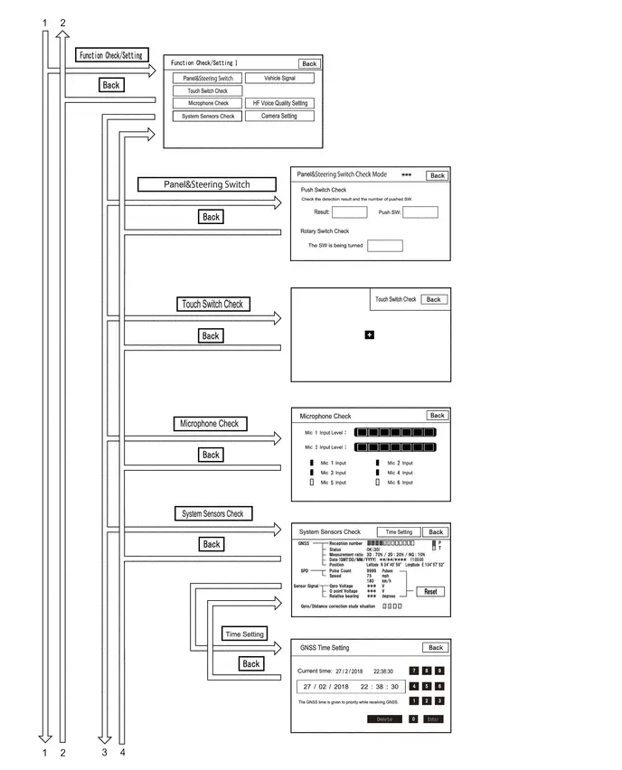
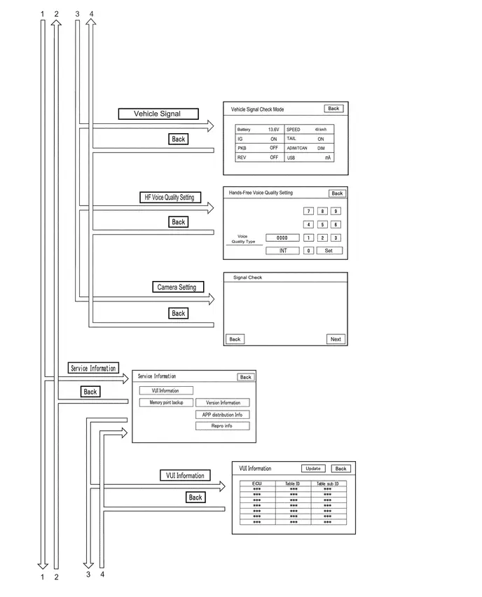
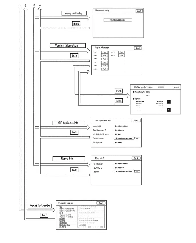
CANCEL DIAGNOSTIC MODE
HINT:
There are 2 methods to cancel diagnosis
(a) Cancellation method 1
(1) Press and hold the VOL switch for 3 seconds or more to restart the system.
(b) Cancellation method 2
(1) Turn the ignition switch off.
SERVICE MENU
HINT:
The service menu screen can be used to perform malfunction diagnosis for each device, confirm functions and information, and collect data.

(a) Failure Diagnosis
Failure Diagnosis Screen Display Contents| Display | Details | Link |
|---|---|---|
| System Check | Display the names of devices connected to the system, and display current and confirmed DTCs as diagnosis results for those devices. |
|
| Diagnosis Recorder | "Bluetooth" connection history and Wi-Fi connection history can be confirmed | - |

HINT:
Each failure diagnosis screen is created by the radio and display receiver assembly.
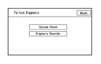
(1) Diagnosis Recorder
Diagnosis Recorder Screen Description| Display | Details | Link |
|---|---|---|
| Delete REC DATA | Recorded history data can be cleared | - |
| Recording ON/OFF | When performing a "Bluetooth" trace or Wi-Fi trace, the recorder function can be set to off | - |
| BT Trace output | "Bluetooth" connection history can be confirmed |
|
| Wi-Fi Trace output | "Wi-Fi" connection history can be confirmed |


HINT:
Each diagnosis recorder screen is created by the radio and display receiver assembly.
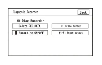
(b) Function Check/Setting I
Function Check/Setting I Screen Description| Display | Content | Link |
|---|---|---|
| Panel&Steering Switch | Checks the operation of the panel switch and steering switch |
|
| Touch Switch Check | Checks the operation of the touch switch of the multi-display | |
| Microphone Check | Checks the connection status of the microphone to the radio and display receiver assembly | |
| System Sensors Check (w/ Navigation System) |
| |
| GNSS Check (w/o Navigation System) |
| |
| Toyota Prius Vehicle Signal | Performs an inspection of vehicle side signal received by the radio and display receiver assembly | |
| HF Voice Quality Setting | HF Voice Quality Setting | |
| Camera Setting (w/ Parking Assist Monitor System) | Performs adjustment of parking assist monitor system |
|
| Camera Setting (w/ panoramic View Monitor System) | Performs adjustment of panoramic view monitor system |
|


HINT:
Each function check/setting I screen is created by the radio and display receiver assembly.
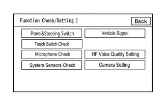
(c) Service Information
HINT:
The service information screen can be used to confirm information and read the memory.
Service Information Screen Description| Display | Content | Link |
|---|---|---|
| VUI Information | Displays information regarding voice recognition |
|
| Memory point backup | Performs memory read using the GTS | - |
| Version Information | Displays connected device version information | - |
| APP distribution Info | Displays in-Toyota Prius vehicle device ID, device identification ID, distribution application PF version, registered user information, etc. | - |
| Repro info | Displays in-vehicle device ID, SCOMO ID, etc. | - |


HINT:
Each service information screen is created by the radio and display receiver assembly.
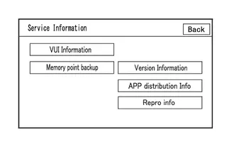
(1) APP distribution Info
APP distribution Info Screen Description| Item | Content |
|---|---|
| in-Toyota Prius vehicle ID | Displays in-vehicle device ID |
| Model discernment ID | Displays model discernment ID |
| APP distribution PF version | Displays platform version that the application uses |
| Connection Server | This item is displayed but is not used |
| User registration | User registration information is displayed |
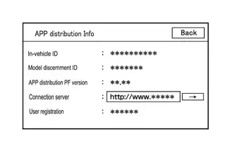
(2) Repro info
Repro Info Screen Display Information| Display | Details |
|---|---|
| In-Toyota Prius vehicle ID | Displays in-vehicle device ID of radio and display receiver assembly |
| SCOMO ID | This item is displayed but is not used |
| Server | This item is displayed but is not used |
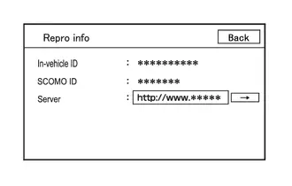
(d) Product Information
Product Information Screen Description| Display | Content |
|---|---|
| VIN | Displays VIN |
| Product Number (AVN) | Displays serial number of the radio and display receiver assembly |
| Product Number (Ext Box) | This item is displayed but is not used |
| HU ID | Displays serial number of the radio and display receiver assembly |
| Chip serial No. (AVN) | Displays IC serial number of the radio and display receiver assembly |
| Chip serial No. (Ext Box) | This item is displayed but is not used |
| DCM IMEI | Displays telematics transceiver IMEI |
| DCM ICCID | Displays telematics transceiver ICCID |
| DCM MSISDN | Displays telematics transceiver MSISDN |
| DCM Contract status | Displays telematics transceiver contract status |
| HELPNET ID | Displays telematics transceiver HELPNET ID |
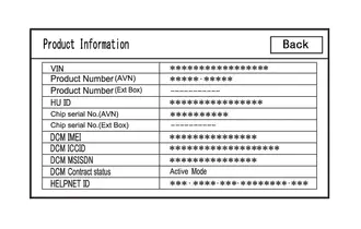
Freeze Frame Data
FREEZE FRAME DATA
HINT:
Whenever a DTC is stored, the ECU stores the current vehicle state as freeze frame data.
CHECK FREEZE FRAME DATA
(a) Select the DTC from "Trouble Codes" screen and display the freeze frame data.
Body Electrical > Navigation System > Trouble Codes(b) Confirm the output freeze frame data.
LIST OF FREEZE FRAME DATA
Body Electrical > Navigation System| Tester Display | Measurement Item | Range | Normal Condition | Diagnostic Note |
|---|---|---|---|---|
| Total Distance Traveled | Distance driven | 0 to 16777215 | Distance driven | - |
| Total Distance Traveled - Unit | Unit when distance driven is displayed | km/mile | Distance driven unit is displayed | - |
| USB Connect Status | USB Connect Status | ON/OFF | OFF: USB not connected ON: USB connected | - |
Data List / Active Test
DATA LIST / ACTIVE TEST
DATA LIST
(a) In accordance with the screen on the GTS, display the Data List screen and check the data.
Body Electrical > Navigation System > Data List| Tester Display | Measurement Item | Range | Normal Condition | Diagnostic Note |
|---|---|---|---|---|
| Total Distance Traveled | Distance driven | 0 to 16777215 | Distance driven | - |
| Total Distance Traveled - Unit | Unit when distance driven is displayed | km/mile | Distance driven unit is displayed | - |
| Navigation Screen Back Light Dimmer | ADIM signal / tail cancel | OFF/ON | ON: Auto-dimming or dimming in accordance with tail cancel signal OFF: No auto-dimming or dimming in accordance with tail cancel signal | w/ Navigation Function |
| Tail Light Switch | TAIL signal (light control switch) status | OFF/ON | ON: Light control switch in TAIL or HEAD position OFF: Light control switch OFF | - |
| Reverse Range Signal | Reverse signal | OFF/ON | ON: Shift lever in R OFF: Shift lever not in R | - |
| Parking Brake | Parking brake switch | OFF/ON | ON: Parking brake applied OFF: Parking brake released | - |
| Ignition Switch | Ignition switch | OFF/ON | ON: Ignition switch ON OFF: Ignition switch off or ACC | An inspection cannot be performed with the ignition switch off as the GTS cannot be used. |
| Battery Voltage | Battery voltage | Min.: 0 V, Max.: 24 V | 11 to 14 V | - |
| Toyota Prius Vehicle Speed | Vehicle speed | Min.: 0 km/h (0 mph), Max.: 255 km/h (158 mph) | A value approximately the same as the actual vehicle speed is displayed | 0 km/h when Toyota Prius vehicle is stopped |
Diagnostic Trouble Code Chart
DIAGNOSTIC TROUBLE CODE CHART
Audio and Visual System| DTC No. | Detection Item | DTC Detection Condition | DTC Output from | Priority | Link |
|---|---|---|---|---|---|
| B153587 | Image Processing Module "B" Video Signal Missing Message | Parking assist ECU video signal error (2 trip detection logic) | Navigation System | B |
|
| B154711 | GNSS Antenna Circuit Short to Ground | Short in GNSS antenna assembly (2 trip detection logic) | Navigation System | A |
|
| B154713 | GNSS Antenna Circuit Open | Open in GNSS antenna assembly (2 trip detection logic) | Navigation System | A |
|
| B154913 | Voice Recognition Microphone2 Circuit Open | Voice recognition microphone 2 terminal (SNS2) disconnected (2 trip detection logic) | Navigation System | A |
|
| B155196 | HD-RADIO Tuner Component Internal Failure | When any of the following conditions is met: (2 trip detection logic)
| Navigation System | A |
|
| B157913 | Voice Recognition Microphone1 Circuit Open | Voice recognition microphone 1 terminal (SNS) disconnected (2 trip detection logic) | Navigation System | A |
|
| B158D87 | Video Signal Stoppage Missing Message | A component internal image signal communication malfunction is detected (2 trip detection logic) | Navigation System | A |
|
| B15A096 | LAN Master Component Internal Failure | When any of the following conditions is met: (2 trip detection logic)
| Navigation System | A |
|
| B15A387 | Stereo Component Amplifier Missing Message | When 60 seconds has elapsed after turning the ignition switch to ON and the stereo component amplifier assembly cannot be detected, the stereo component amplifier assembly is judged to be disconnected after comparison with the past registered devices history. (2 trip detection logic) | Navigation System | A |
|
| B15A396 | Stereo Component Amplifier Component Internal Failure | When any of the following conditions is met: (2 trip detection logic)
| Navigation System | A |
|
| B15AD96 | Navigation Processor Component Internal Failure | When any of the following conditions is met: (2 trip detection logic)
| Navigation System | A |
|
| B15B396 | Radio Tuner Component Internal Failure | A radio tuner internal communication malfunction is detected (2 trip detection logic) | Navigation System | A |
|
| B15B796 | Bluetooth Module Component Internal Failure | A "Bluetooth" module internal malfunction is detected (2 trip detection logic) | Navigation System | A |
|
| B15BA96 | XM Tuner Component Internal Failure | When any of the following conditions is met: (2 trip detection logic)
| Navigation System | A |
|
| B15C371 | Speaker Output Short Actuator Stuck | When any of the following conditions is met: (2 trip detection logic)
| Navigation System | A |
|
| B15DB87 | Telematics Transceiver Missing Message | When 90 seconds has elapsed after turning the ignition switch to ON and the DCM (telematics transceiver) cannot be detected, the DCM (telematics transceiver) is judged to be disconnected after comparison with the past USB connected devices information. (2 trip detection logic) | Navigation System | A |
|
| B15FE11 | XM Tuner Antenna Circuit Short to Ground | The XM antenna is not connected. (2 trip detection logic) | Navigation System | A |
|
| B15FE13 | XM Tuner Antenna Circuit Open | A short occurs in the XM antenna. (2 trip detection logic) | Navigation System | A |
|
| B1ACA71 | Front Right Speaker Cable Actuator Stuck | Open in the front speaker RH circuit is detected. (1 trip detection logic) | Navigation System | A |
|
| B1ACB71 | Front Left Speaker Cable Actuator Stuck | Navigation System | A |
| |
| B1ACC71 | Rear Door Right Speaker Cable Actuator Stuck | Open in the rear speaker RH circuit is detected. (1 trip detection logic) | Navigation System | A |
|
| B1ACD71 | Rear Door Left Speaker Cable Actuator Stuck | Open in the rear speaker LH circuit is detected. (1 trip detection logic) | Navigation System | A |
|
| B228231 | Toyota Prius Vehicle Speed Signal Circuit Open | When the GNSS position is stable and the vehicle speed is approximately 44 km/h or more, the vehicle speed pulse signal is not detected for 120 seconds or more. (2 trip detection logic) | Navigation System | A |
|
| C162287 | Rear Camera Image Signal Missing Message | When the ignition switch is ON, a malfunction is detected in the image signal of the rear television camera assembly (2 trip detection logic) | Navigation System | B |
|
| U010087 | Lost Communication With ECM/PCM "A" Missing Message | Communication malfunction between radio and display receiver assembly and Engine/EV ECU for 12 seconds or more | Navigation System | B |
|
| U012987 | Lost Communication With Brake System Control Module Missing Message | Communication malfunction between radio and display receiver assembly and No. 2 skid control ECU (brake actuator assembly) for 11 seconds or more (2 trip detection logic) | Navigation System | B |
|
| U014087 | Lost Communication with Body Control Module Missing Message | Communication malfunction between radio and display receiver assembly and main body ECU (multiplex network body ECU) for 11 seconds or more (2 trip detection logic) | Navigation System | B |
|
| U015587 | Lost Communication with Instrument Panel Cluster (IPC) Control Module Missing Message | Communication malfunction between radio and display receiver assembly and combination meter assembly for 31 seconds or more | Navigation System | B |
|
| U016487 | Lost Communication with HVAC Control Module Missing Message | Communication malfunction between radio and display receiver assembly and air conditioning amplifier assembly for 10 seconds or more (2 trip detection logic) | Navigation System | B |
|
| U016887 | Lost Communication with Toyota Prius Vehicle Security Control Module Missing Message | Communication malfunction between radio and display receiver assembly and certification ECU (smart key ECU assembly) for 11 seconds or more (2 trip detection logic) | Navigation System | B |
|
| U019887 | Lost Communication with Telematic Control Module "A" Missing Message | Communication malfunction between radio and display receiver assembly and telematics transceiver for 3 seconds or more (2 trip detection logic) | Navigation System | B |
|
| U029387 | Lost Communication with Hybrid/EV Powertrain Control Module Missing Message | Communication malfunction between radio and display receiver assembly and hybrid Toyota Prius vehicle control ECU for 11 seconds or more (2 trip detection logic) | Navigation System | B |
|
| U100049 | CAN Register Fixing Internal Electronic Failure |
(2 trip detection logic) | Navigation System | B |
|
| U111087 | Lost Communication with Clearance Sonar Module | Communication malfunction between radio and display receiver assembly and clearance warning ECU assembly for 11 seconds or more (2 trip detection logic) | Navigation System | B |
|
| U11D087 | Lost Local Communication with MET Missing Message | Communication malfunction between radio and display receiver assembly and combination meter assembly for 30 seconds or more (2 trip detection logic) | Navigation System | A |
|


VEHICLE CONTROL HISTORY (RoB)
VEHICLE CONTROL HISTORY (RoB)
NOTICE:
When checking the vehicle control history (RoB), record any stored history first.
Check Vehicle Control History (RoB) (w/ Navigation Function)
(a) In accordance with the display of the GTS, check the vehicle control history (RoB).
Body Electrical > Navigation System > Utility| Tester Display |
|---|
| Toyota Prius Vehicle Control History (RoB) |
| Code | Item | Description | Note |
|---|---|---|---|
| X20B0 | Circumference Monitoring Camera Control Module Malfunction | Radio and display receiver assembly is storing history from when a panoramic view monitor system malfunction was received | Perform troubleshooting for the panoramic view monitor system.
HINT: Stored when a panoramic view monitor system malfunction is received by the radio and display receiver assembly via CAN communication. |
| X20B1 | Rear Camera Malfunction | Radio and display receiver assembly is storing history from when a back guide monitor malfunction was received | Perform troubleshooting for the back guide monitor system.
HINT: Stored when a back guide monitor malfunction notification is received by the radio and display receiver assembly via CAN communication. |
| X3FF0 | Over The Air Activation Start | Radio and display receiver assembly is storing history from when CAN microcomputer OTA started | - |
| X3FF1 | Over The Air Activation Stop | Radio and display receiver assembly is storing history from when CAN microcomputer OTA ended | - |
| X8020 | Video/Sound Signal Malfunction | Radio and display receiver assembly is storing history from when an auxiliary battery low voltage (6.75 V or less) was detected |
HINT: When the auxiliary battery voltage becomes low (5.0 to 6.8 V), images are blacked out and audio is muted. |
| X8021 | Touch Switch Stuck | Radio and display receiver assembly is storing history from when a stuck touch switch was detected |
|
| X8022 | Initialization History | Radio and display receiver assembly is storing history from when an intended initialization operation was detected | HINT: Explain to the customer that the radio and display receiver assembly stores a history of an intended initialization operation using the multi-display. |
| X8023 | Navi Kit Use History | Radio and display receiver assembly is storing history from when the Toyota Prius vehicle speed signal was off, the parking brake signal was on and DTC B228231 was detected |
HINT: For the detection conditions of DTC B228231, refer to
|
| X8024 | Position Corrected History | Radio and display receiver assembly is storing history from when the location calibration was 50 m or more | Refer to problem symptoms table (Toyota Prius Vehicle position mark deviates from correct position and does not return to correct position)
|
| X8030 | Soft Update (USB Reading Error) | Radio and display receiver assembly is storing history from when a USB memory error was detected | HINT: Explain to the customer that any of the following could be the cause:
|
| X8031 | Soft Update (Encryption Release Error) | Radio and display receiver assembly is storing history from when a program update error was detected | HINT: Explain to the customer that any of the following could be the cause:
|
| X8032 | Soft Update (Program of Different Model) | History of detection of update program error stored by the radio and display receiver assembly | HINT: Explain to the customer that the update program was judged to be for a different device. |
| X8033 | USB Memory Malfunction (The File System Error) | Radio and display receiver assembly is storing history from when a non-compatible file or malfunctioning USB storage device was connected to the stereo jack adapter assembly | Connect a USB storage device with valid files. HINT: Explain to the customer that any of the following could be the cause:
|
| X8034 | USB Memory Malfunction (With No Playable File) | Radio and display receiver assembly is storing history from when no playable files on a USB storage device connected to the stereo jack adapter assembly was detected | Connect a USB storage device that has playable files. HINT: Explain to the customer that there were no playable files on the USB storage device. |
| X8038 | iPod Malfunction | Radio and display receiver assembly is storing history from when a malfunctioning iPod was connected to the stereo jack adapter assembly |
HINT:
|
| X8039 | iPod Malfunction (With Control Software) | Radio and display receiver assembly is storing history from when there was a malfunction of the control software of an iPod connected to the stereo jack adapter assembly | |
| X803A | iPod Malfunction (With Communication Error) | Radio and display receiver assembly is storing history from when a communication error with an iPod connected to the stereo jack adapter assembly was detected | |
| X803B | iPod Malfunction (With No Playable File) | Radio and display receiver assembly is storing history from when no playable files on an iPod connected to the stereo jack adapter assembly was detected | Connect an iPod that has playable files. HINT:
|
| X803C | SD Card Communication Malfunction | Radio and display receiver assembly is storing history from when an SD card malfunction was detected | If the malfunction continues to recur, replace the radio and display receiver assembly.
HINT: Explain to the customer that an internal SD malfunction has been detected by the radio and display receiver assembly. |
| X8080 | AMP Malfunction (Temperature High) | Stereo component amplifier assembly is storing history from when it was detected that the stereo component amplifier assembly temperature was above a certain value (approximately 150°C) |
HINT: The stereo component amplifier assembly will return to normal when the temperature drops below a certain value (approximately 150°C or less). |
| X8081 | AMP Malfunction (High Output Sound Source) | Stereo component amplifier assembly is storing history from when high output sound source similar to direct current was continuously detected (low frequency or square wave continued) | HINT: Explain to the customer that a high output sound source similar to direct current (low frequency or square wave continued to be output) was detected. |
| X8082 | AMP Malfunction (Short Circuit) | Stereo component amplifier assembly is storing history from when a direct current load on a speaker output circuit was detected | HINT: Refer to DTC B15C371.
|
| X8087 | AMP Malfunction (ANC Communication Error) | Stereo component amplifier assembly is storing history from when an ANC ECU (stereo component equalizer assembly) communication malfunction was detected |
|


NOTICE:
By performing this procedure, all stored Toyota Prius vehicle control history (RoB) will be cleared.
Clear Vehicle Control History (RoB)
(a) Using the GTS, select the vehicle control history (RoB).
Body Electrical > Navigation System > Utility| Tester Display |
|---|
| Toyota Prius Vehicle Control History (RoB) |
(b) Select the clear button and the clear vehicle control history (RoB) in accordance with the screen.
Image Processing Module "B" Video Signal Missing Message (B153587)
DESCRIPTION
This DTC is stored when a video signal line is disconnected.
| DTC No. | Detection Item | DTC Detection Condition | Trouble Area | DTC Output from | Priority |
|---|---|---|---|---|---|
| B153587 | Image Processing Module "B" Video Signal Missing Message | Parking assist ECU video signal error (2 trip detection logic) |
| Navigation System | B |
- *: w/ Panoramic view monitor system
WIRING DIAGRAM
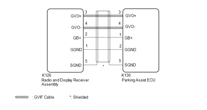
CAUTION / NOTICE / HINT
NOTICE:
Depending on the parts that are replaced during Toyota Prius vehicle inspection or maintenance, performing initialization, registration or calibration may be needed.
Click here

PROCEDURE
| 1. | CHECK PANORAMIC VIEW MONITOR SYSTEM |
(a) Check if the panoramic view system is malfunctioning.
HINT:
Click here


| Result | Proceed to |
|---|---|
| Malfunction does not occur | A |
| Malfunction occurs | B |
| B |

| GO TO PANORAMIC VIEW MONITOR SYSTEM
|


|

| 2. | CHECK HARNESS AND CONNECTOR (RADIO AND DISPLAY RECEIVER ASSEMBLY - PARKING ASSIST ECU) |
Pre-procedure1
(a) Disconnect the K126 radio and display receiver assembly connector.
(b) Disconnect the K139 parking assist ECU connector.
Procedure1
(c) Measure the resistance according to the value(s) in the table below.
Standard Resistance:
 Click Location & Routing(K126) Click Connector(K126)
 | Tester Connection | Condition | Specified Condition | Result |
|---|---|---|---|
| K126-2 (GB ) - K139-1 (GB ) | Always | Below 1 Ω | Ω |
| K126-3 (GVO ) - K139-3 (GVO ) | Always | Below 1 Ω | Ω |
| K126-4 (GVO-) - K139-4 (GVO-) | Always | Below 1 Ω | Ω |
| K126-1 (GGND) - K139-2 (GGND) | Always | Below 1 Ω | Ω |
| K126-5 (SGND) - K139-5 (SGND) | Always | Below 1 Ω | Ω |
| K126-2 (GB ) or K139-1 (GB ) - Body ground | Always | 10 kΩ or higher | kΩ |
| K126-3 (GVO ) or K139-3 (GVO ) - Body ground | Always | 10 kΩ or higher | kΩ |
| K126-4 (GVO-) or K139-4 (GVO-) - Body ground | Always | 10 kΩ or higher | kΩ |
| K126-1 (GGND) or K139-2 (GGND) - Body ground | Always | 10 kΩ or higher | kΩ |
| K126-5 (SGND) or K139-5 (SGND) - Body ground | Always | 10 kΩ or higher | kΩ |
Post-procedure1
(d) None
| OK |

| REPLACE RADIO AND DISPLAY RECEIVER ASSEMBLY |
| NG |

| REPAIR OR REPLACE HARNESS OR CONNECTOR |
GNSS Antenna Circuit Short to Ground (B154711,B154713)
DESCRIPTION
These DTCs are stored when the radio and display receiver assembly detects an open or short in GNSS antenna assembly.
| DTC No. | Detection Item | DTC Detection Condition | Trouble Area | DTC Output from | Priority |
|---|---|---|---|---|---|
| B154711 | GNSS Antenna Circuit Short to Ground | Short in GNSS antenna assembly (2 trip detection logic) |
| Navigation System | A |
| B154713 | GNSS Antenna Circuit Open | Open in GNSS antenna assembly (2 trip detection logic) |
| Navigation System | A |
WIRING DIAGRAM
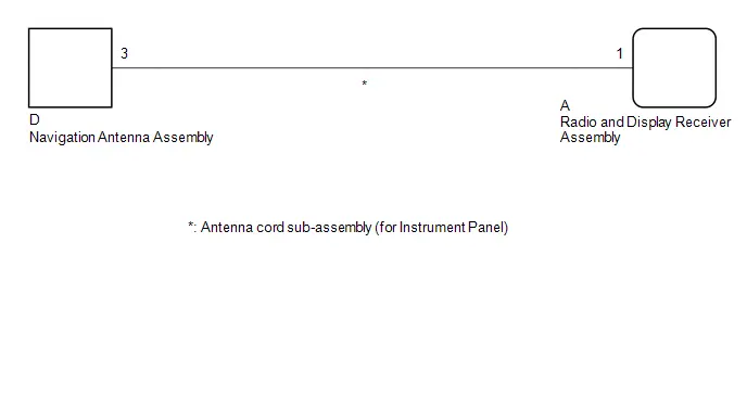
CAUTION / NOTICE / HINT
NOTICE:
Depending on the parts that are replaced during Toyota Prius vehicle inspection or maintenance, performing initialization, registration or calibration may be needed.
Click here

PROCEDURE
| 1. | CHECK MODEL |
(a) Choose the model to be inspected.
| Result | Proceed to |
|---|---|
| w/ DCM (Telematics Transceiver) | A |
| w/o DCM (Telematics Transceiver) | B |
| B |

| GO TO STEP 4 |
|

| 2. | INSPECT NAVIGATION ANTENNA ASSEMBLY |
HINT:
Click here

| NG |

| REPLACE NAVIGATION ANTENNA ASSEMBLY
|


|

| 3. | INSPECT ANTENNA CORD SUB-ASSEMBLY (for Instrument Panel) |
Pre-procedure1
| (a) Disconnect the navigation antenna assembly connector. |
|

| (b) Disconnect the radio and display receiver assembly connector. |
|

Procedure1
(c) Measure the resistance according to the value(s) in the table below.
Standard Resistance:
| Tester Connection | Condition | Specified Condition | Result |
|---|---|---|---|
| D-3 - A-1 | Always | Below 1 Ω | Ω |
| D-3a - A-1a | Always | Below 1 Ω | Ω |
| D-3a or A-1a - Body ground | Always | 10 kΩ or higher | kΩ |
Post-procedure1
(d) None
| OK |

| REPLACE RADIO AND DISPLAY RECEIVER ASSEMBLY |
| NG |

| REPLACE ANTENNA CORD SUB-ASSEMBLY (for Instrument Panel)
|


| 4. | INSPECT NAVIGATION ANTENNA ASSEMBLY |
HINT:
Click here

| NG |

| REPLACE NAVIGATION ANTENNA ASSEMBLY
|


|

| 5. | INSPECT ANTENNA CORD SUB-ASSEMBLY (for Instrument Panel) |
Pre-procedure1
| (a) Disconnect the navigation antenna assembly connector. |
|
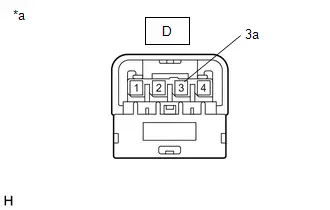
| (b) Disconnect the radio and display receiver assembly connector. |
|
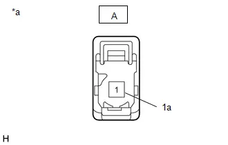
Procedure1
(c) Measure the resistance according to the value(s) in the table below.
Standard Resistance:
| Tester Connection | Condition | Specified Condition | Result |
|---|---|---|---|
| D-3 - A-1 | Always | Below 1 Ω | Ω |
| D-3a - A-1a | Always | Below 1 Ω | Ω |
| D-3a or A-1a - Body ground | Always | 10 kΩ or higher | kΩ |
Post-procedure1
(d) None
| OK |

| REPLACE RADIO AND DISPLAY RECEIVER ASSEMBLY |
| NG |

| REPLACE ANTENNA CORD SUB-ASSEMBLY (for Instrument Panel)
|


Voice Recognition Microphone2 Circuit Open (B154913)
DESCRIPTION
The telephone microphone assembly RH is connected to the radio and display receiver assembly via voice recognition microphone 2 signal detection line.
This DTC is stored when the radio and display receiver assembly detects disconnection of telephone microphone assembly RH.
| DTC No. | Detection Item | DTC Detection Condition | Trouble Area | DTC Output from | Priority |
|---|---|---|---|---|---|
| B154913 | Voice Recognition Microphone2 Circuit Open | Voice recognition microphone 2 terminal (SNS2) disconnected (2 trip detection logic) |
| Navigation System | A |
- *: w/ DCM (Telematics transceiver)
WIRING DIAGRAM
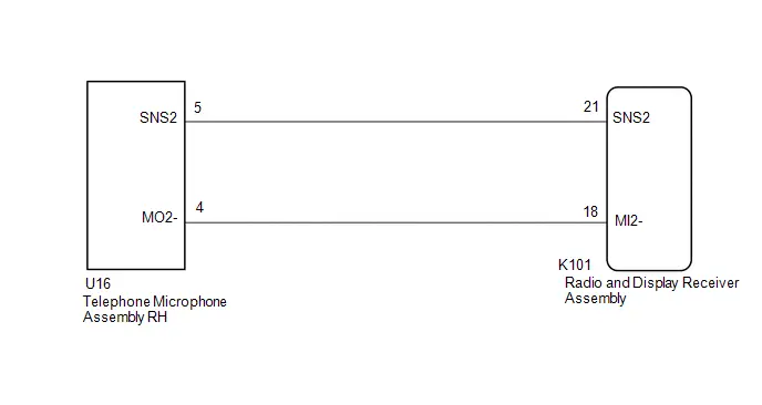
CAUTION / NOTICE / HINT
NOTICE:
- When replacing the telematics transceiver, make sure to replace it with a new one (w/ Telematics Transceiver).
-
Depending on the parts that are replaced during Toyota Prius vehicle inspection or maintenance, performing initialization, registration or calibration may be needed.
Click here

PROCEDURE
| 1. | CHECK HARNESS AND CONNECTOR (RADIO AND DISPLAY RECEIVER ASSEMBLY - TELEPHONE MICROPHONE ASSEMBLY RH) |
Pre-procedure1
(a) Disconnect the K101 radio and display receiver assembly connector.
(b) Disconnect the U16 telephone microphone assembly RH connector.
Procedure1
(c) Measure the resistance according to the value(s) in the table below.
Standard Resistance:
 Click Location & Routing(K101,U16) Click Connector(K101) Click Connector(U16)
 | Tester Connection | Condition | Specified Condition | Result |
|---|---|---|---|
| K101-21 (SNS2) - U16-5 (SNS2) | Always | Below 1 Ω | Ω |
| K101-18 (MI2-) - U16-4 (MO2-) | Always | Below 1 Ω | Ω |
| K101-21 (SNS2) or U16-5 (SNS2) - Body ground | Always | 10 kΩ or higher | kΩ |
| K101-18 (MI2-) or U16-4 (MO2-) - Body ground | Always | 10 kΩ or higher | kΩ |
Post-procedure1
(d) None
| NG |

| REPAIR OR REPLACE HARNESS OR CONNECTOR |
|

| 2. | INSPECT RADIO & DISPLAY RECEIVER ASSEMBLY (MI2-) |
Pre-procedure1
(a) With the radio and display receiver assembly connectors connected, disconnect the U16 telephone microphone assembly RH connector.
Procedure1
(b) Measure the resistance according to the value(s) in the table below.
Standard Resistance:
 Click Location & Routing(U16) Click Connector(U16)
 | Tester Connection | Condition | Specified Condition | Result |
|---|---|---|---|
| U16-4 (MO2-) - Body ground | Always | Below 1 Ω | Ω |
Post-procedure1
(c) None
| NG |

| REPLACE RADIO AND DISPLAY RECEIVER ASSEMBLY |
|

| 3. | INSPECT TELEPHONE MICROPHONE ASSEMBLY RH (SNS2, MO2-) |
Pre-procedure1
| (a) Remove the telephone microphone assembly RH. |
|
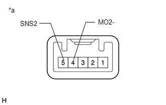
Procedure1
(b) Measure the resistance according to the value(s) in the table below.
Standard Resistance:
| Tester Connection | Condition | Specified Condition | Result |
|---|---|---|---|
| 5 (SNS2) - 4 (MO2-) | Always | Below 1 Ω | Ω |
Post-procedure1
(c) None
| OK |

| REPLACE RADIO AND DISPLAY RECEIVER ASSEMBLY |
| NG |

| REPLACE TELEPHONE MICROPHONE ASSEMBLY RH
|


HD-RADIO Tuner Component Internal Failure (B155196,B158D87,B15A096,B15AD96,B15B396,B15B796,B15BA96)
DESCRIPTION
These DTCs are stored when a malfunction occurs in the radio and display receiver assembly.
| DTC No. | Detection Item | DTC Detection Condition | Trouble Area | DTC Output from | Priority |
|---|---|---|---|---|---|
| B155196 | HD-RADIO Tuner Component Internal Failure | When any of the following conditions is met: (2 trip detection logic)
| Radio and display receiver assembly | Navigation System | A |
| B158D87 | Video Signal Stoppage Missing Message | A component internal image signal communication malfunction is detected (2 trip detection logic) | Radio and display receiver assembly | Navigation System | A |
| B15A096 | LAN Master Component Internal Failure | When any of the following conditions is met: (2 trip detection logic)
| Radio and display receiver assembly | Navigation System | A |
| B15AD96 | Navigation Processor Component Internal Failure | When any of the following conditions is met: (2 trip detection logic)
| Radio and display receiver assembly | Navigation System | A |
| B15B396 | Radio Tuner Component Internal Failure | A radio tuner internal communication malfunction is detected (2 trip detection logic) | Radio and display receiver assembly | Navigation System | A |
| B15B796 | Bluetooth Module Component Internal Failure | A "Bluetooth" module internal malfunction is detected (2 trip detection logic) | Radio and display receiver assembly | Navigation System | A |
| B15BA96 | XM Tuner Component Internal Failure | When any of the following conditions is met: (2 trip detection logic)
| Radio and display receiver assembly | Navigation System | A |
CAUTION / NOTICE / HINT
NOTICE:
Depending on the parts that are replaced during Toyota Prius vehicle inspection or maintenance, performing initialization, registration or calibration may be needed.
Click here

PROCEDURE
| 1. | CLEAR DTC |
(a) Clear the DTCs.
Body Electrical > Navigation System > Clear DTCs
|

| 2. | CHECK DTC |
Pre-procedure1
(a) Turn the ignition switch off.
Procedure1
(b) Check for DTCs.
Body Electrical > Navigation System > Trouble Codes| Result | Proceed to |
|---|---|
| DTCs are not output | A |
| B155196, B158D87, B15A096, B15AD96, B15B396, B15B796 or B15BA96 is output | B |
Post-procedure1
(c) None
| A |

| GO TO HOW TO PROCEED WITH TROUBLESHOOTING |
| B |

| REPLACE RADIO AND DISPLAY RECEIVER ASSEMBLY |
Voice Recognition Microphone1 Circuit Open (B157913)
DESCRIPTION
The telephone microphone assembly LH is connected to the radio and display receiver assembly via voice recognition microphone 1 signal detection line.
This DTC is stored when the radio and display receiver assembly detects disconnection of telephone microphone assembly LH.
| DTC No. | Detection Item | DTC Detection Condition | Trouble Area | DTC Output from | Priority |
|---|---|---|---|---|---|
| B157913 | Voice Recognition Microphone1 Circuit Open | Voice recognition microphone 1 terminal (SNS) disconnected (2 trip detection logic) |
| Navigation System | A |
- *: w/ DCM (Telematics Transceiver)
WIRING DIAGRAM
w/ DCM (Telematics Transceiver)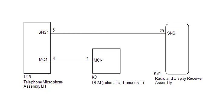 w/o DCM (Telematics Transceiver)
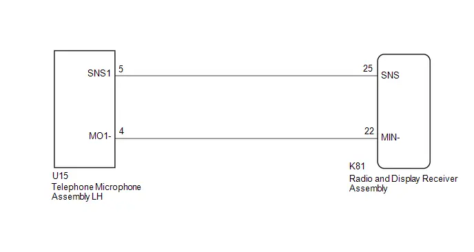
CAUTION / NOTICE / HINT
NOTICE:
- When replacing the telematics transceiver, make sure to replace it with a new one (w/ Telematics Transceiver).
-
Depending on the parts that are replaced during Toyota Prius vehicle inspection or maintenance, performing initialization, registration or calibration may be needed.
Click here

PROCEDURE
| 1. | CHECK MODEL |
| Result | Proceed to |
|---|---|
| w/ DCM(Telematics Transceiver) | A |
| w/o DCM (Telematics transceiver) | B |
| B |

| GO TO STEP 4 |
|

| 2. | CHECK HARNESS AND CONNECTOR (TELEPHONE MICROPHONE ASSEMBLY LH - RADIO AND DISPLAY RECEIVER ASSEMBLY, TELEMATICS TRANSCEIVER) |
Pre-procedure1
(a) Disconnect the U15 telephone microphone assembly LH connector.
(b) Disconnect the K81 radio and display receiver assembly connector.
(c) Disconnect the K9 telematics transceiver connector.
Procedure1
(d) Measure the resistance according to the value(s) in the table below.
Standard Resistance:
 Click Location & Routing(U15,K81,K9) Click Connector(U15) Click Connector(K81) Click Connector(K9)
 | Tester Connection | Condition | Specified Condition | Result |
|---|---|---|---|
| U15-5 (SNS1) - K81-25 (SNS) | Always | Below 1 Ω | Ω |
| U15-4 (MO1-) - K9-7 (MCI-) | Always | Below 1 Ω | Ω |
| U15-5 (SNS1) or K81-25 (SNS) - Body ground | Always | 10 kΩ or higher | kΩ |
| U15-4 (MO1-) or K9-7 (MCI-) - Body ground | Always | 10 kΩ or higher | kΩ |
Post-procedure1
(e) None
| NG |

| REPAIR OR REPLACE HARNESS OR CONNECTOR |
|

| 3. | INSPECT TELEMATICS TRANSCEIVER (MCI-) |
Pre-procedure1
(a) With the telematics transceiver connectors connected, disconnect the U15 telephone microphone assembly LH connector.
Procedure1
(b) Measure the resistance according to the value(s) in the table below.
Standard Resistance:
 Click Location & Routing(U15) Click Connector(U15)
 | Tester Connection | Condition | Specified Condition | Result |
|---|---|---|---|
| U15-4 (MO1-) - Body ground | Always | Below 1 Ω | Ω |
Post-procedure1
(c) None
| OK |

| GO TO STEP 6 |
| NG |

| REPLACE DCM (TELEMATICS TRANSCEIVER) |
| 4. | CHECK HARNESS AND CONNECTOR (RADIO AND DISPLAY RECEIVER ASSEMBLY - TELEPHONE MICROPHONE ASSEMBLY LH) |
Pre-procedure1
(a) Disconnect the K81 radio and display receiver assembly connector.
(b) Disconnect the U15 telephone microphone assembly LH connector.
Procedure1
(c) Measure the resistance according to the value(s) in the table below.
Standard Resistance:
 Click Location & Routing(U15,K81) Click Connector(U15) Click Connector(K81)
 | Tester Connection | Condition | Specified Condition | Result |
|---|---|---|---|
| U15-5 (SNS1) - K81-25 (SNS) | Always | Below 1 Ω | Ω |
| U15-4 (MO1-) - K81-22 (MIN-) | Always | Below 1 Ω | Ω |
| U15-5 (SNS1) or K81-25 (SNS) - Body ground | Always | 10 kΩ or higher | kΩ |
| U15-4 (MO1-) or K81-22 (MIN-) - Body ground | Always | 10 kΩ or higher | kΩ |
Post-procedure1
(d) None
| NG |

| REPAIR OR REPLACE HARNESS OR CONNECTOR |
|

| 5. | INSPECT RADIO & DISPLAY RECEIVER ASSEMBLY (MIN-) |
Pre-procedure1
(a) With the radio and display receiver assembly connectors connected, disconnect the U15 telephone microphone assembly LH connector.
Procedure1
(b) Measure the resistance according to the value(s) in the table below.
Standard Resistance:
 Click Location & Routing(U15) Click Connector(U15)
 | Tester Connection | Condition | Specified Condition | Result |
|---|---|---|---|
| U15-4 (MO1-) - Body ground | Always | Below 1 Ω | Ω |
Post-procedure1
(c) None
| NG |

| REPLACE RADIO AND DISPLAY RECEIVER ASSEMBLY |
|

| 6. | INSPECT TELEPHONE MICROPHONE ASSEMBLY LH (SNS1, MO1-) |
Pre-procedure1
| (a) Remove the telephone microphone assembly LH. |
|
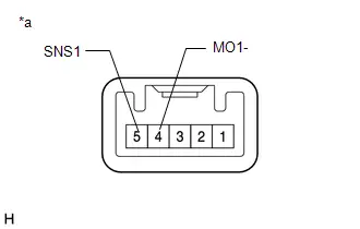
Procedure1
(b) Measure the resistance according to the value(s) in the table below.
Standard Resistance:
| Tester Connection | Condition | Specified Condition | Result |
|---|---|---|---|
| 5 (SNS1) - 4 (MO1-) | Always | Below 1 Ω | Ω |
Post-procedure1
(c) None
| OK |

| REPLACE RADIO & DISPLAY RECEIVER ASSEMBLY |
| NG |

| REPLACE TELEPHONE MICROPHONE ASSEMBLY LH
|


Stereo Component Amplifier Missing Message (B15A387)
DESCRIPTION
This DTC is stored when the radio and display receiver assembly detects that the stereo component amplifier assembly has disconnected.
| DTC No. | Detection Item | DTC Detection Condition | Trouble Area | DTC Output from | Priority |
|---|---|---|---|---|---|
| B15A387 | Stereo Component Amplifier Missing Message | When 60 seconds has elapsed after turning the ignition switch to ON and the stereo component amplifier assembly cannot be detected, the stereo component amplifier assembly is judged to be disconnected after comparison with the past registered devices history. (2 trip detection logic) |
| Navigation System | A |
WIRING DIAGRAM
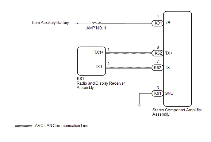
CAUTION / NOTICE / HINT
NOTICE:
- Inspect the fuses for circuits related to this system before performing the following procedure.
-
Depending on the parts that are replaced during Toyota Prius vehicle inspection or maintenance, performing initialization, registration or calibration may be needed.
Click here

HINT:
There may be a communication malfunction due to noise affecting communication between devices on the AVC-LAN.
PROCEDURE
| 1. | CHECK HARNESS AND CONNECTOR (STEREO COMPONENT AMPLIFIER ASSEMBLY - POWER SOURCE AND BODY GROUND) |
Pre-procedure1
(a) Disconnect the K91 stereo component amplifier assembly connector.
Procedure1
(b) Measure the resistance according to the value(s) in the table below.
Standard Resistance:
 Click Location & Routing(K91) Click Connector(K91)
 | Tester Connection | Condition | Specified Condition | Result |
|---|---|---|---|
| K91-3 (GND) - Body ground | Always | Below 1 Ω | Ω |
(c) Measure the voltage according to the value(s) in the table below.
Standard Voltage:
 Click Location & Routing(K91) Click Connector(K91)
 | Tester Connection | Condition | Specified Condition | Result |
|---|---|---|---|
| K91-1 ( B) - Body ground | Always*1 IG OFF*2 | 11 to 14 V | V |
- *1: for Gasoline Model
- *2: for HV Model
Post-procedure1
(d) None
| NG |

| REPAIR OR REPLACE HARNESS OR CONNECTOR |
|

| 2. | CHECK HARNESS AND CONNECTOR (RADIO AND DISPLAY RECEIVER ASSEMBLY - STEREO COMPONENT AMPLIFIER ASSEMBLY) |
Pre-procedure1
(a) Disconnect the K81 radio and display receiver assembly connector.
(b) Disconnect the K62 stereo component amplifier assembly connector.
Procedure1
(c) Measure the resistance according to the value(s) in the table below.
Standard Resistance:
 Click Location & Routing(K81,K62) Click Connector(K81) Click Connector(K62)
 | Tester Connection | Condition | Specified Condition | Result |
|---|---|---|---|
| K81-1 (TX1 ) - K62-8 (TX ) | Always | Below 1 Ω | Ω |
| K81-2 (TX1-) - K62-7 (TX-) | Always | Below 1 Ω | Ω |
| K81-1 (TX1 ) or K62-8 (TX ) - Body ground | Always | 10 kΩ or higher | kΩ |
| K81-2 (TX1-) or K62-7 (TX-) - Body ground | Always | 10 kΩ or higher | kΩ |
Post-procedure1
(d) None
| NG |

| REPAIR OR REPLACE HARNESS OR CONNECTOR |
|

| 3. | REPLACE STEREO COMPONENT AMPLIFIER ASSEMBLY |
(a) Replace the stereo component amplifier assembly with a new or known good one.
HINT:
Click here


|

| 4. | CLEAR DTC |
(a) Clear the DTCs.
Body Electrical > Navigation System > Clear DTCs
|

| 5. | CHECK FOR DTC |
Pre-procedure1
(a) Turn the ignition switch off.
(b) Turn the ignition switch to ON and wait for 60 seconds.
(c) Turn the ignition switch off.
(d) Turn the ignition switch to ON and wait for 60 seconds.
Procedure1
(e) Check for DTCs and proceed to the following step.
Body Electrical > Navigation System > Trouble Codes| Result | Proceed to |
|---|---|
| B15A387 is not output | A |
| B15A387 is output | B |
Post-procedure1
(f) None
| A |

| END (STEREO COMPONENT AMPLIFIER ASSEMBLY IS DEFECTIVE) |
| B |

| REPLACE RADIO AND DISPLAY RECEIVER ASSEMBLY |
Stereo Component Amplifier Component Internal Failure (B15A396)
DESCRIPTION
This DTC is stored when a malfunction occurs in the stereo component amplifier assembly.
| DTC No. | Detection Item | DTC Detection Condition | Trouble Area | DTC Output from | Priority |
|---|---|---|---|---|---|
| B15A396 | Stereo Component Amplifier Component Internal Failure | When any of the following conditions is met: (2 trip detection logic)
| Stereo component amplifier assembly | Navigation System | A |
PROCEDURE
| 1. | CLEAR DTC |
(a) Clear the DTCs.
Body Electrical > Navigation System > Clear DTCs
|

| 2. | CHECK FOR DTC |
Pre-procedure1
(a) Turn the ignition switch off.
Procedure1
(b) Check for DTCs and proceed to the following step.
Body Electrical > Navigation System > Trouble Codes| Result | Proceed to |
|---|---|
| B15A396 is not output | A |
| B15A396 is output | B |
Post-procedure1
(c) None
| A |

| GO TO HOW TO PROCEED WITH TROUBLESHOOTING |
| B |

| REPLACE STEREO COMPONENT AMPLIFIER ASSEMBLY
|


Speaker Output Short Actuator Stuck (B15C371)
DESCRIPTION
This DTC is stored when the stereo component amplifier assembly*1 or radio and display receiver assembly*2 detects a short in a speaker circuit.
| DTC No. | Detection Item | DTC Detection Condition | Trouble Area | DTC Output from | Priority |
|---|---|---|---|---|---|
| B15C371 | Speaker Output Short Actuator Stuck | When any of the following conditions is met: (2 trip detection logic)
|
| Navigation System | A |
- *1: with "JBL" Sound System
- *2: without "JBL" Sound System
WIRING DIAGRAM
w/o "JBL" Sound System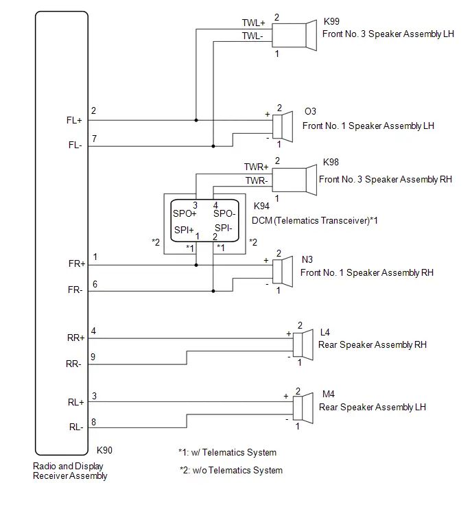 w/ "JBL" Sound System
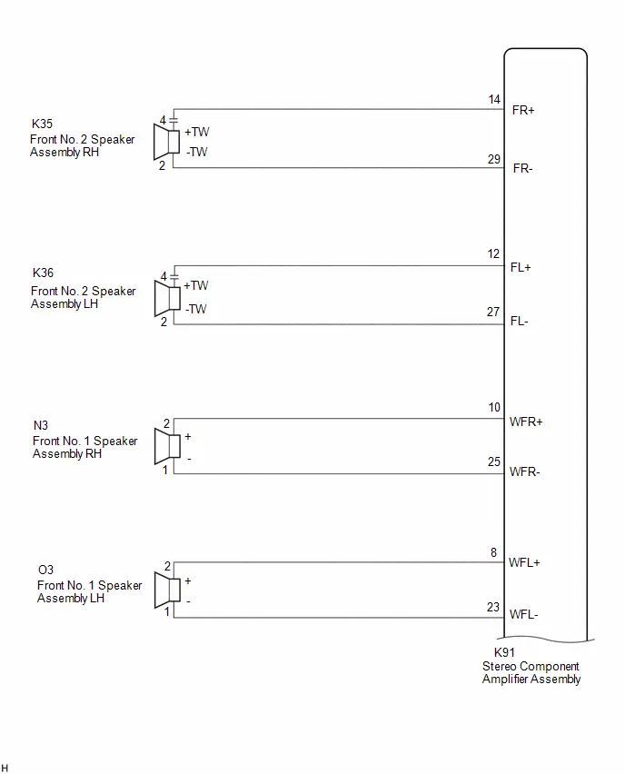
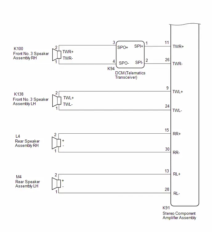
CAUTION / NOTICE / HINT
NOTICE:
Depending on the parts that are replaced during Toyota Prius vehicle inspection or maintenance, performing initialization, registration or calibration may be needed.
Click here

PROCEDURE
| 1. | CHECK MODEL |
(a) Choose the model to be inspected.
| Result | Proceed to |
|---|---|
| w/o "JBL" Sound System with Telematics Transceiver | A |
| w/o "JBL" Sound System without Telematics Transceiver | B |
| w/ "JBL" Sound System | C |
| B |

| GO TO STEP 10 |
| C |

| GO TO STEP 17 |
|

| 2. | CHECK HARNESS AND CONNECTOR (RADIO AND DISPLAY RECEIVER ASSEMBLY - EACH SPEAKER AND DCM (TELEMATICS TRANSCEIVER)) |
Pre-procedure1
(a) Disconnect the K90 radio and display receiver assembly connector.
(b) Disconnect the K94 DCM (telematics transceiver) connector.
(c) Disconnect the K99 front No. 3 speaker assembly LH connector.
(d) Disconnect the O3 and N3 front No. 1 speaker assembly connector.
(e) Disconnect the L4 and M4 rear speaker assembly connectors.
Procedure1
(f) Measure the resistance according to the value(s) in the table below.
Standard Resistance:
 Click Location & Routing(K90,K94,N3,K99,O3,L4,M4) Click Connector(K90) Click Connector(K94) Click Connector(N3) Click Connector(K99) Click Connector(O3) Click Connector(L4) Click Connector(M4)
 | Tester Connection | Condition | Specified Condition | Result |
|---|---|---|---|
| K90-1 (FR ) or K94-1 (SPI ) - Body ground | Always | 10 kΩ or higher | kΩ |
| K90-6 (FR-) or K94-2 (SPI-) - Body ground | Always | 10 kΩ or higher | kΩ |
| K90-1 (FR ) or N3-2 ( ) - Body ground | Always | 10 kΩ or higher | kΩ |
| K90-6 (FR-) or N3-1 (-) - Body ground | Always | 10 kΩ or higher | kΩ |
| K90-2 (FL ) or K99-2 (TWL ) - Body ground | Always | 10 kΩ or higher | kΩ |
| K90-7 (FL-) or K99-1 (TWL-) - Body ground | Always | 10 kΩ or higher | kΩ |
| K90-2 (FL ) or O3-2 ( ) - Body ground | Always | 10 kΩ or higher | kΩ |
| K90-7 (FL-) or K99-1 (-) - Body ground | Always | 10 kΩ or higher | kΩ |
| K90-4 (RR ) or L4-2 ( ) - Body ground | Always | 10 kΩ or higher | kΩ |
| K90-9 (RR-) or L4-1 (-) - Body ground | Always | 10 kΩ or higher | kΩ |
| K90-3 (RL ) or M4-2 ( ) - Body ground | Always | 10 kΩ or higher | kΩ |
| K90-8 (RL-) or M4-1 (-) - Body ground | Always | 10 kΩ or higher | kΩ |
Post-procedure1
(g) None
| NG |

| REPAIR OR REPLACE HARNESS OR CONNECTOR |
|

| 3. | CHECK HARNESS AND CONNECTOR (DCM (TELEMATICS TRANSCEIVER) - FRONT NO. 3 SPEAKER ASSEMBLY RH) |
Pre-procedure1
(a) Disconnect the K94 DCM (telematics transceiver) connector.
(b) Disconnect the K98 front No. 3 speaker assembly RH connector.
Procedure1
(c) Measure the resistance according to the value(s) in the table below.
Standard Resistance:
 Click Location & Routing(K94,K98) Click Connector(K94) Click Connector(K98)
 | Tester Connection | Condition | Specified Condition | Result |
|---|---|---|---|
| K94-3 (SPO ) or K98-2 (TWR ) - Body ground | Always | 10 kΩ or higher | kΩ |
| K94-4 (SPO-) or K98-1 (TWR-) - Body ground | Always | 10 kΩ or higher | kΩ |
Post-procedure1
(d) None
| NG |

| REPAIR OR REPLACE HARNESS OR CONNECTOR |
|

| 4. | INSPECT FRONT NO. 1 SPEAKER ASSEMBLY |
HINT:
Click here

| NG |

| REPLACE FRONT NO. 1 SPEAKER ASSEMBLY |
|

| 5. | INSPECT REAR SPEAKER ASSEMBLY |
HINT:
Click here

| NG |

| REPLACE REAR SPEAKER ASSEMBLY |
|

| 6. | INSPECT TELEMATICS TRANSCEIVER |
Pre-procedure1
| (a) Disconnect the telematics transceiver connector. |
|

Procedure1
(b) Measure the resistance according to the value(s) in the table below.
Standard Resistance:
| Tester Connection | Condition | Specified Condition | Result |
|---|---|---|---|
| 1 (SPI ) - 3 (SPO ) | Always | Below 1 Ω | Ω |
| 2 (SPI-) - 4 (SPO-) | Always | Below 1 Ω | Ω |
| 1 (SPI ) - 2 (SPI-) | Always | 10 kΩ or higher | kΩ |
| 3 (SPO ) - 4 (SPO-) | Always | 10 kΩ or higher | kΩ |
Post-procedure1
(c) None
| NG |

| REPLACE DCM (TELEMATICS TRANSCEIVER) |
|

| 7. | REPLACE FRONT NO.3 SPEAKER ASSEMBLY |
(a) Replace the speaker assembly with a new or known good one.
HINT:
Click here

|

| 8. | CLEAR DTC |
(a) Clear the DTCs.
Body Electrical > Navigation System > Clear DTCs
|

| 9. | CHECK FOR DTC |
Pre-procedure1
(a) Turn the ignition switch off.
Procedure1
(b) Check for DTCs and proceed to the following step.
Body Electrical > Navigation System > Trouble Codes| Result | Proceed to |
|---|---|
| B15C371 is not output | A |
| B15C371 is output | B |
Post-procedure1
(c) None
| A |

| END |
| B |

| REPLACE RADIO AND DISPLAY RECEIVER ASSEMBLY |
| 10. | CHECK HARNESS AND CONNECTOR (RADIO AND DISPLAY RECEIVER ASSEMBLY - EACH SPEAKER) |
Pre-procedure1
(a) Disconnect the K90 radio and display receiver assembly connector.
(b) Disconnect the K98 and K99 front No. 3 speaker assembly connectors.
(c) Disconnect the L4 and M4 rear speaker assembly connectors.
Procedure1
(d) Measure the resistance according to the value(s) in the table below.
Standard Resistance:
 Click Location & Routing(K90,K98,K99,L4,M4) Click Connector(K90) Click Connector(K98) Click Connector(K99) Click Connector(L4) Click Connector(M4)
 | Tester Connection | Condition | Specified Condition | Result |
|---|---|---|---|
| K90-1 (FR ) or K98-4 (TWR ) - Body ground | Always | 10 kΩ or higher | kΩ |
| K90-6 (FR-) or K98-2 (TWR-) - Body ground | Always | 10 kΩ or higher | kΩ |
| K90-2 (FL ) or K99-4 (TWL ) - Body ground | Always | 10 kΩ or higher | kΩ |
| K90-7 (FL-) or K99-2 (TWL-) - Body ground | Always | 10 kΩ or higher | kΩ |
| K90-4 (RR ) or L4-2 ( ) - Body ground | Always | 10 kΩ or higher | kΩ |
| K90-9 (RR-) or L4-1 (-) - Body ground | Always | 10 kΩ or higher | kΩ |
| K90-3 (RL ) or M4-2 ( ) - Body ground | Always | 10 kΩ or higher | kΩ |
| K90-8 (RL-) or M4-1 (-) - Body ground | Always | 10 kΩ or higher | kΩ |
Post-procedure1
(e) None
| NG |

| REPAIR OR REPLACE HARNESS OR CONNECTOR |
|

| 11. | CHECK HARNESS AND CONNECTOR (FRONT NO. 1 SPEAKER ASSEMBLY - FRONT NO. 3 SPEAKER ASSEMBLY) |
Pre-procedure1
(a) Disconnect the N3 and O3 front No. 1 speaker assembly connectors.
(b) Disconnect the K98 and K99 front No. 3 speaker assembly connectors.
Procedure1
(c) Measure the resistance according to the value(s) in the table below.
Standard Resistance:
 Click Location & Routing(O3,K99,N3,K98) Click Connector(O3) Click Connector(K99) Click Connector(N3) Click Connector(K98)
 | Tester Connection | Condition | Specified Condition | Result |
|---|---|---|---|
| O3-2 or K99-2 ( ) - Body ground | Always | 10 kΩ or higher | kΩ |
| O3-1 or K99-1 (-) - Body ground | Always | 10 kΩ or higher | kΩ |
| N3-2 or K98-2 ( ) - Body ground | Always | 10 kΩ or higher | kΩ |
| N3-1 or K98-1 (-) - Body ground | Always | 10 kΩ or higher | kΩ |
Post-procedure1
(d) None
| NG |

| REPAIR OR REPLACE HARNESS OR CONNECTOR |
|

| 12. | INSPECT FRONT NO. 1 SPEAKER ASSEMBLY |
HINT:
Click here

| NG |

| REPLACE FRONT NO. 1 SPEAKER ASSEMBLY |
|

| 13. | INSPECT REAR SPEAKER ASSEMBLY |
HINT:
Click here

| NG |

| REPLACE REAR SPEAKER ASSEMBLY |
|

| 14. | REPLACE FRONT NO.3 SPEAKER ASSEMBLY |
(a) Replace the speaker assembly with a new or known good one.
HINT:
Click here

|

| 15. | CLEAR DTC |
(a) Clear the DTCs.
Body Electrical > Navigation System > Clear DTCs
|

| 16. | CHECK FOR DTC |
Pre-procedure1
(a) Turn the ignition switch off.
Procedure1
(b) Check for DTCs and proceed to the following step.
Body Electrical > Navigation System > Trouble Codes| Result | Proceed to |
|---|---|
| B15C371 is not output | A |
| B15C371 is output | B |
Post-procedure1
(c) None
| A |

| END |
| B |

| REPLACE RADIO AND DISPLAY RECEIVER ASSEMBLY |
| 17. | CHECK HARNESS AND CONNECTOR (STEREO COMPONENT AMPLIFIER ASSEMBLY - EACH SPEAKER AND DCM (TELEMATICS TRANSCEIVER)) |
Pre-procedure1
(a) Disconnect the K91 stereo component amplifier assembly connector.
(b) Disconnect the K94 DCM (telematics transceiver) connector.
(c) Disconnect the K138 front No. 3 speaker assembly LH connector.
(d) Disconnect the K35 and K36 front No. 2 speaker assembly connectors.
(e) Disconnect the L4 and M4 rear speaker assembly connectors.
(f) Disconnect the O3 and N3 front No. 1 speaker assembly connectors.
Procedure1
(g) Measure the resistance according to the value(s) in the table below.
Standard Resistance:
 Click Location & Routing(K91,K94,K138,K35,K36,L4,M4,N3,O3) Click Connector(K91) Click Connector(K94) Click Connector(K138) Click Connector(K35) Click Connector(K36) Click Connector(L4) Click Connector(M4) Click Connector(N3) Click Connector(O3)
 | Tester Connection | Condition | Specified Condition | Result |
|---|---|---|---|
| K91-11 (TWR ) or K94-1 (SPI ) - Body ground | Always | 10 kΩ or higher | kΩ |
| K91-26 (TWR-) or K94-2 (SPI-) - Body ground | Always | 10 kΩ or higher | kΩ |
| K91-9 (TWL ) or K138-2 (TWL ) - Body ground | Always | 10 kΩ or higher | kΩ |
| K91-24 (TWL-) or K138-1 (TWL-) - Body ground | Always | 10 kΩ or higher | kΩ |
| K91-14 (FR ) or K35-4 ( TW) - Body ground | Always | 10 kΩ or higher | kΩ |
| K91-29 (FR-) or K35-2 (-TW) - Body ground | Always | 10 kΩ or higher | kΩ |
| K91-12 (FL ) or K36-4 ( TW) - Body ground | Always | 10 kΩ or higher | kΩ |
| K91-27 (FL-) or K36-2 (-TW) - Body ground | Always | 10 kΩ or higher | kΩ |
| K91-15 (RR ) or L4-2 ( ) - Body ground | Always | 10 kΩ or higher | kΩ |
| K91-30 (RR-) or L4-1 (-) - Body ground | Always | 10 kΩ or higher | kΩ |
| K91-13 (RL ) or M4-2 ( ) - Body ground | Always | 10 kΩ or higher | kΩ |
| K91-28 (RL-) or M4-1 (-) - Body ground | Always | 10 kΩ or higher | kΩ |
| K91-10 (WFR ) or N3-2 ( ) - Body ground | Always | 10 kΩ or higher | kΩ |
| K91-25 (WFR-) or N3-3 (-) - Body ground | Always | 10 kΩ or higher | kΩ |
| K91-8 (WFL ) or O3-2 ( ) - Body ground | Always | 10 kΩ or higher | kΩ |
| K91-23 (WFL-) or O3-1 (-) - Body ground | Always | 10 kΩ or higher | kΩ |
Post-procedure1
(h) None
| NG |

| REPAIR OR REPLACE HARNESS OR CONNECTOR |
|

| 18. | CHECK HARNESS AND CONNECTOR (DCM (TELEMATICS TRANSCEIVER) - FRONT NO. 3 SPEAKER ASSEMBLY) |
Pre-procedure1
(a) Disconnect the K94 DCM (telematics transceiver) connector.
(b) Disconnect the K100 front No. 3 speaker assembly RH connector.
Procedure1
(c) Measure the resistance according to the value(s) in the table below.
Standard Resistance:
 Click Location & Routing(K94,K100) Click Connector(K94) Click Connector(K100)
 | Tester Connection | Condition | Specified Condition | Result |
|---|---|---|---|
| K94-3 (SPO ) or K100-2 (TWR ) - Body ground | Always | 10 kΩ or higher | kΩ |
| K94-4 (SPO-) or K100-1 (TWR-) - Body ground | Always | 10 kΩ or higher | kΩ |
Post-procedure1
(d) None
| NG |

| REPAIR OR REPLACE HARNESS OR CONNECTOR |
|

| 19. | INSPECT FRONT NO. 1 SPEAKER ASSEMBLY |
HINT:
Click here

| NG |

| REPLACE FRONT NO. 1 SPEAKER ASSEMBLY |
|

| 20. | INSPECT FRONT NO.3 SPEAKER ASSEMBLY |
HINT:
Click here

| NG |

| REPLACE FRONT NO.3 SPEAKER ASSEMBLY |
|

| 21. | INSPECT REAR SPEAKER ASSEMBLY |
HINT:
Click here

| NG |

| REPLACE REAR SPEAKER ASSEMBLY |
|

| 22. | INSPECT DCM (TELEMATICS TRANSCEIVER) |
Pre-procedure1
(a) Remove the DCM (telematics transceiver).
HINT:
Click here

Procedure1
| (b) Measure the resistance according to the value(s) in the table below. Standard Resistance:
Result:
|
|
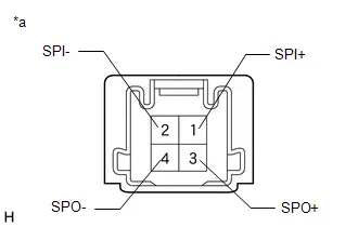
Post-procedure1
(c) None
| NG |

| REPLACE DCM (TELEMATICS TRANSCEIVER) |
|

| 23. | REPLACE FRONT NO.2 SPEAKER ASSEMBLY |
(a) Replace the speaker assembly with a new or known good one.
HINT:
Click here

|

| 24. | CLEAR DTC |
(a) Clear the DTCs.
Body Electrical > Navigation System > Clear DTCs
|

| 25. | CHECK FOR DTC |
Pre-procedure1
(a) Turn the ignition switch off.
Procedure1
(b) Check for DTCs and proceed to the following step.
Body Electrical > Navigation System > Trouble Codes| Result | Proceed to |
|---|---|
| B15C371 is not output | A |
| B15C371 is output | B |
Post-procedure1
(c) None
| A |

| END |
| B |

| REPLACE STEREO COMPONENT AMPLIFIER ASSEMBLY
|


Telematics Transceiver Missing Message (B15DB87)
DESCRIPTION
When the radio and display receiver assembly cannot detect the DCM (telematics transceiver), this DTC will be stored.
| DTC No. | Detection Item | DTC Detection Condition | Trouble Area | DTC Output from | Priority |
|---|---|---|---|---|---|
| B15DB87 | Telematics Transceiver Missing Message | When 90 seconds has elapsed after turning the ignition switch to ON and the DCM (telematics transceiver) cannot be detected, the DCM (telematics transceiver) is judged to be disconnected after comparison with the past USB connected devices information. (2 trip detection logic) |
| Navigation System | A |
WIRING DIAGRAM
CAUTION / NOTICE / HINT
NOTICE:
- Inspect the fuses for circuits related to this system before performing the following procedure.
- When replacing the DCM (telematics transceiver), make sure to replace it with a new one.
-
Depending on the parts that are replaced during Toyota Prius vehicle inspection or maintenance, performing initialization, registration or calibration may be needed. Refer to Precaution for Audio and Visual System.
Click here

HINT:
- The Telematics System performs communication between devices via USB communication. If a malfunction such as a short in a communication line, short to B or short to ground occurs in the USB circuit, communication will stop and the Telematics System will not operate correctly.
- This DTC may be stored due to environmental reasons such as electrical noise or interference.
PROCEDURE
| 1. | CLEAR DTC |
(a) Clear the DTCs.
Body Electrical > Navigation System > Clear DTCs
|
| 2. | CHECK DTC |
Pre-procedure1
(a) Turn the ignition switch off.
Procedure1
(b) Check for DTCs.
Body Electrical > Navigation System > Trouble Codes| Result | Proceed to |
|---|---|
| B15DB87 is not output | A |
| B15DB87 is output | B |
Post-procedure1
(c) None
| A |
| USE SIMULATION METHOD TO CHECK |
|
| 3. | CHECK HARNESS AND CONNECTOR (DCM [TELEMATICS TRANSCEIVER] POWER SOURCE) |
Pre-procedure1
(a) Disconnect the K9 DCM (telematics transceiver) connector.
Procedure1
(b) Measure the resistance according to the value(s) in the table below.
Standard Resistance:
| Tester Connection | Condition | Specified Condition | Result |
|---|---|---|---|
| K9-20 (E) - Body ground | Always | Below 1 Ω | Ω |
(c) Measure the voltage according to the value(s) in the table below.
Standard Voltage:
| Tester Connection | Condition | Specified Condition | Result |
|---|---|---|---|
| K9-1 ( B) - K9-20 (E) | Ignition switch off | 11 to 14 V | V |
| K9-19 (IG2) - K9-20 (E) | Ignition switch ON | 11 to 14 V | V |
Post-procedure1
(d) None
| NG |
| REPAIR OR REPLACE HARNESS OR CONNECTOR |
|
| 4. | CHECK HARNESS AND CONNECTOR (RADIO AND DISPLAY RECEIVER ASSEMBLY - DCM [TELEMATICS TRANSCEIVER]) |
Pre-procedure1
(a) Disconnect the K81 radio and display receiver assembly connector.
(b) Disconnect the K9 DCM (telematics transceiver) connector.
Procedure1
(c) Measure the resistance according to the value(s) in the table below.
Standard Resistance:
| Tester Connection | Condition | Specified Condition | Result |
|---|---|---|---|
| K81-18 (USBV) - K9-15 (USBV) | Always | Below 1 Ω | Ω |
| K81-17 (USBG) - K9-31 (USBG) | Always | Below 1 Ω | Ω |
| K81-18 (USBV) - Body ground | Always | 10 kΩ or higher | kΩ |
| K81-17 (USBG) - Body ground | Always | 10 kΩ or higher | kΩ |
Post-procedure1
(d) None
| NG |
| REPAIR OR REPLACE HARNESS OR CONNECTOR |
|
| 5. | INSPECT RADIO AND DISPLAY RECEIVER ASSEMBLY (USBV, USBG) |
Pre-procedure1
(a) With the radio and display receiver assembly connectors connected, disconnect the K9 DCM (telematics transceiver) connector.
Procedure1
(b) Measure the resistance according to the value(s) in the table below.
Standard Resistance:
| Tester Connection | Condition | Specified Condition | Result |
|---|---|---|---|
| K9-31 (USBG) - Body ground | Always | Below 1 Ω | Ω |
(c) Measure the voltage according to the value(s) in the table below.
Standard Voltage:
| Tester Connection | Switch Condition | Specified Condition | Result |
|---|---|---|---|
| K9-15 (USBV) - K9-31 (USBG) | Ignition switch ON | 3 V or higher | V |
Post-procedure1
(d) None
| NG |
| REPLACE RADIO AND DISPLAY RECEIVER ASSEMBLY |
|
| 6. | CHECK HARNESS AND CONNECTOR (RADIO AND DISPLAY RECEIVER ASSEMBLY - DCM [TELEMATICS TRANSCEIVER]) |
Pre-procedure1
| (a) Disconnect the K124 radio and display receiver assembly connector. |
|
(b) Disconnect the K125 DCM (telematics transceiver) connector.
Procedure1
(c) Measure the resistance according to the value(s) in the table below.
Standard Resistance:
| Tester Connection | Condition | Specified Condition | Result |
|---|---|---|---|
| K124-1 (USB ) - K125-2 (USB ) | Always | Below 1 Ω | Ω |
| K124-2 (USB-) - K125-1 (USB-) | Always | Below 1 Ω | Ω |
| K124-3 (USBS) - K125-3 (USBS) | Always | Below 1 Ω | Ω |
| K124-1 (USB ) - Body ground | Always | 10 kΩ or higher | kΩ |
| K124-2 (USB-) - Body ground | Always | 10 kΩ or higher | kΩ |
| K124-3 (USBS) - Body ground | Always | 10 kΩ or higher | kΩ |
Post-procedure1
(d) None
| NG |
| REPAIR OR REPLACE HARNESS OR CONNECTOR |
|
| 7. | REPLACE DCM (TELEMATICS TRANSCEIVER) |
(a) Replace the DCM (telematics transceiver) with a new one.
HINT:
Click here
![]()
|
| 8. | CLEAR DTC |
(a) Clear the DTCs.
Body Electrical > Navigation System > Clear DTCs
|
| 9. | CHECK FOR DTC |
Pre-procedure1
(a) Turn the ignition switch off.
(b) Turn the ignition switch to ON and wait for 90 seconds.
(c) Turn the ignition switch off.
(d) Turn the ignition switch to ON and wait for 90 seconds.
Procedure1
(e) Using the GTS, recheck for DTCs and proceed to the following step.
Body Electrical > Navigation System > Trouble Codes| Result | Proceed to |
|---|---|
| B15DB87 is not output | A |
| B15DB87 is output | B |
Post-procedure1
(f) None
| A |
| END (DCM [TELEMATICS TRANSCEIVER] IS DEFECTIVE) |
| B |
| REPLACE RADIO AND DISPLAY RECEIVER ASSEMBLY |
XM Tuner Antenna Circuit Short to Ground (B15FE11,B15FE13)
DESCRIPTION
These DTCs are stored when a malfunction occurs in the roof antenna assembly which is connected to the radio and display receiver assembly.
| DTC No. | Detection Item | DTC Detection Condition | Trouble Area | DTC Output from | Priority |
|---|---|---|---|---|---|
| B15FE11 | XM Tuner Antenna Circuit Short to Ground | The XM antenna is not connected. (2 trip detection logic) |
| Navigation System | A |
| B15FE13 | XM Tuner Antenna Circuit Open | A short occurs in the XM antenna. (2 trip detection logic) |
| Navigation System | A |
WIRING DIAGRAM
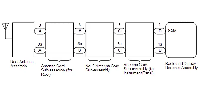
CAUTION / NOTICE / HINT
NOTICE:
Depending on the parts that are replaced during Toyota Prius vehicle inspection or maintenance, performing initialization, registration or calibration may be needed. Refer to Precaution for Audio and Visual System.
Click here

PROCEDURE
| 1. | CHECK CONNECTION OF ANTENNA CABLE |
(a) Check if the roof antenna assembly cable is securely connected to the radio and display receiver assembly.
OK:
Roof antenna assembly cable is securely connected.
| NG |

| SECURELY CONNECT ROOF ANTENNA ASSEMBLY |
|

| 2. | CLEAR DTC |
(a) Clear the DTCs.
Body Electrical > Navigation System > Clear DTCs
|

| 3. | CHECK FOR DTC |
Pre-procedure1
(a) Turn the ignition switch off.
Procedure1
(b) Recheck for DTCs and check that no DTCs are output.
Body Electrical > Navigation System > Trouble Codes| Result | Proceed to |
|---|---|
| DTCs are not output | A |
| B15FE11 or B15FE13 is output | B |
Post-procedure1
(c) None
| A |

| USE SIMULATION METHOD TO CHECK |
|

| 4. | CHECK ANTENNA CORD SUB-ASSEMBLY (for Roof) |
Pre-procedure1
| (a) Disconnect the antenna connector from the roof antenna assembly. |
|
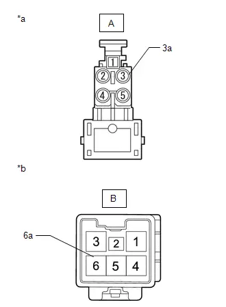
(b) Disconnect the antenna connector from the No. 3 antenna cord sub-assembly.
Procedure1
(c) Measure the resistance according to the value(s) in the table below.
Standard Resistance:
| Tester Connection | Condition | Specified Condition | Result |
|---|---|---|---|
| A-3 - B-6 | Always | Below 1 Ω | Ω |
| A-3a - B-6a | Always | Below 1 Ω | Ω |
| A-3 - Body ground | Always | 10 kΩ or higher | kΩ |
Post-procedure1
(d) None
| NG |

| REPLACE ANTENNA CORD SUB-ASSEMBLY (for Roof)
|


|

| 5. | CHECK NO. 3 ANTENNA CORD SUB-ASSEMBLY |
Pre-procedure1
| (a) Disconnect the antenna connector from the antenna cord sub-assembly (for Roof). |
|
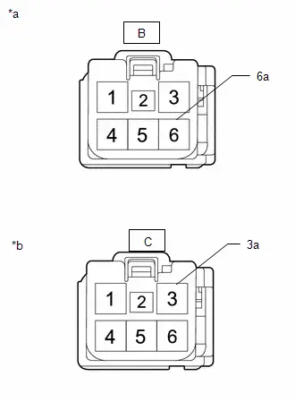
(b) Disconnect the antenna connector from the antenna cord sub-assembly (for Instrument Panel).
Procedure1
(c) Measure the resistance according to the value(s) in the table below.
Standard Resistance:
| Tester Connection | Condition | Specified Condition | Result |
|---|---|---|---|
| B-6 - C-3 | Always | Below 1 Ω | Ω |
| B-6a - C-3a | Always | Below 1 Ω | Ω |
| B-6 - Body ground | Always | 10 kΩ or higher | kΩ |
Post-procedure1
(d) None
| NG |

| REPLACE NO. 3 ANTENNA CORD SUB-ASSEMBLY
|


|

| 6. | CHECK ANTENNA CORD SUB-ASSEMBLY |
Pre-procedure1
| (a) Disconnect the antenna connector from the No. 3 antenna cord sub-assembly. |
|
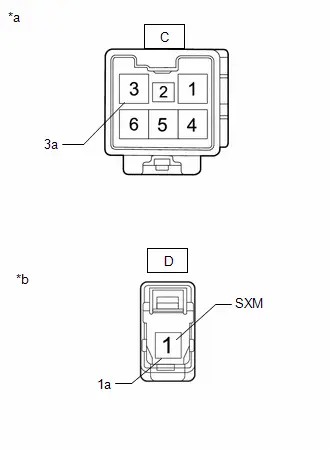
(b) Disconnect the antenna connector from the radio and display receiver assembly.
Procedure1
(c) Measure the resistance according to the value(s) in the table below.
Standard Resistance:
| Tester Connection | Condition | Specified Condition | Result |
|---|---|---|---|
| C-3 - D-1 (SXM) | Always | Below 1 Ω | Ω |
| C-3a - D-1a | Always | Below 1 Ω | Ω |
| C-3 - Body ground | Always | 10 kΩ or higher | kΩ |
Post-procedure1
(d) None
| NG |

| REPLACE ANTENNA CORD SUB-ASSEMBLY (for Instrument Panel)
|


|

| 7. | REPLACE ROOF ANTENNA ASSEMBLY |
(a) Replace the roof antenna assembly with a new or known good one.
HINT:
Click here


|

| 8. | CLEAR DTC |
(a) Clear the DTCs.
Body Electrical > Navigation System > Clear DTCs
|

| 9. | CHECK DTC |
Pre-procedure1
(a) Turn the ignition switch off.
Procedure1
(b) Recheck for DTCs and check that no DTCs are output.
Body Electrical > Navigation System > Trouble Codes| Result | Proceed to |
|---|---|
| DTCs are not output | A |
| B15FE11 or B15FE13 is output | B |
Post-procedure1
(c) None
| A |

| END (ROOF ANTENNA ASSEMBLY IS DEFECTIVE) |
| B |

| REPLACE RADIO AND DISPLAY RECEIVER ASSEMBLY |
Front Right Speaker Cable Actuator Stuck (B1ACA71)
DESCRIPTION
This DTC is stored when the stereo component amplifier assembly detects an open in the front speaker RH circuit by energizing the speaker line.
| DTC No. | Detection Item | DTC Detection Condition | Trouble Area | DTC Output from | Priority |
|---|---|---|---|---|---|
| B1ACA71 | Front Right Speaker Cable Actuator Stuck | Open in the front speaker RH circuit is detected. (1 trip detection logic) |
| Navigation System | A |
WIRING DIAGRAM
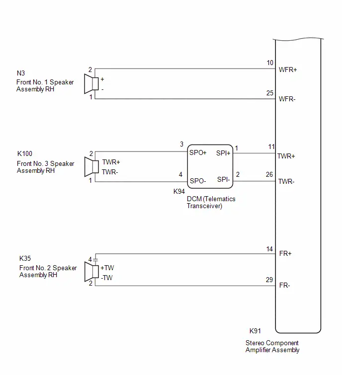
PROCEDURE
| 1. | CHECK PROBLEM SYMPTOM |
(a) Confirm the problem symptoms and proceed to the respective link.
| Result | Proceed to |
|---|---|
| No sound is output from the front No. 1 speaker assembly RH or front No. 2 speaker assembly RH | A |
| No sound is output from the front No. 3 speaker assembly RH | B |
| B |

| GO TO STEP 9 |
|

| 2. | CHECK HARNESS AND CONNECTOR (STEREO COMPONENT AMPLIFIER ASSEMBLY - FRONT NO.1 SPEAKER ASSEMBLY RH AND NO. 2 SPEAKER ASSEMBLY RH) |
Pre-procedure1
(a) Disconnect the K91 stereo component amplifier assembly connector.
(b) Disconnect the N3 front No. 1 speaker assembly RH connector.
(c) Disconnect the K35 front No. 2 speaker assembly RH connector.
Procedure1
(d) Measure the resistance according to the value(s) in the table below.
Standard Resistance:
 Click Location & Routing(K91,K35,N3) Click Connector(K91) Click Connector(K35) Click Connector(N3)
 | Tester Connection | Condition | Specified Condition | Result |
|---|---|---|---|
| K91-14 (FR ) - K35-4 ( TW) | Always | Below 1 Ω | Ω |
| K91-29 (FR-) - K35-2 (-TW) | Always | Below 1 Ω | Ω |
| K91-10 (WFR ) - N3-2 ( ) | Always | Below 1 Ω | Ω |
| K91-25 (WFR-) - N3-1 (-) | Always | Below 1 Ω | Ω |
Post-procedure1
(e) None
| NG |

| REPAIR OR REPLACE HARNESS OR CONNECTOR |
|

| 3. | INSPECT FRONT NO. 1 SPEAKER ASSEMBLY RH |
HINT:
Click here

| NG |

| REPLACE FRONT NO. 1 SPEAKER ASSEMBLY RH |
|

| 4. | CLEAR DTC |
(a) Clear the DTCs.
Body Electrical > Navigation System > Clear DTCs
|

| 5. | CHECK FOR DTC |
Pre-procedure1
(a) In accordance with the display of the GTS, perform a speaker circuit energization inspection.
HINT:
Click here

| Tester Display |
|---|
| Speaker Line Electricity Check |
Procedure1
(b) Check for DTCs and proceed to the following step.
Body Electrical > Navigation System > Trouble Codes| Result | Proceed to |
|---|---|
| B1ACA71 is not output | A |
| B1ACA71 is output | B |
Post-procedure1
(c) None
| A |

| END (FRONT NO. 1 SPEAKER ASSEMBLY RH IS DEFECTIVE) |
|

| 6. | REPLACE FRONT NO. 2 SPEAKER ASSEMBLY |
(a) Replace the speaker assembly with a new or known good one.
HINT:
Click here

|

| 7. | CLEAR DTC |
(a) Clear the DTCs.
Body Electrical > Navigation System > Clear DTCs
|

| 8. | CHECK FOR DTC |
Pre-procedure1
(a) In accordance with the display of the GTS, perform a speaker circuit energization inspection.
HINT:
Click here

| Tester Display |
|---|
| Speaker Line Electricity Check |
Procedure1
(b) Check for DTCs and proceed to the following step.
Body Electrical > Navigation System > Trouble Codes| Result | Proceed to |
|---|---|
| B1ACA71 is not output | A |
| B1ACA71 is output | B |
Post-procedure1
(c) None
| A |

| END (FRONT NO. 2 SPEAKER ASSEMBLY RH IS DEFECTIVE) |
| B |

| REPLACE STEREO COMPONENT AMPLIFIER ASSEMBLY
|


| 9. | CHECK HARNESS AND CONNECTOR (STEREO COMPONENT AMPLIFIER ASSEMBLY - DCM (TELEMATICS TRANSCEIVER)) |
Pre-procedure1
(a) Disconnect the K91 stereo component amplifier assembly connector.
(b) Disconnect the K94 DCM (telematics transceiver) connector.
Procedure1
(c) Measure the resistance according to the value(s) in the table below.
Standard Resistance:
 Click Location & Routing(K91,K94) Click Connector(K91) Click Connector(K94)
 | Tester Connection | Condition | Specified Condition | Result |
|---|---|---|---|
| K91-11 (TWR ) - K94-1 (SPI ) | Always | Below 1 Ω | Ω |
| K91-26 (TWR-) - K94-2 (SPI-) | Always | Below 1 Ω | Ω |
Post-procedure1
(d) None
| NG |

| REPAIR OR REPLACE HARNESS OR CONNECTOR |
|

| 10. | CHECK HARNESS AND CONNECTOR (DCM (TELEMATICS TRANSCEIVER) - FRONT NO. 3 SPEAKER ASSEMBLY) |
Pre-procedure1
(a) Disconnect the K94 DCM (telematics transceiver) connector.
(b) Disconnect the K100 front No. 3 speaker assembly RH connector.
Procedure1
(c) Measure the resistance according to the value(s) in the table below.
Standard Resistance:
 Click Location & Routing(K94,K100) Click Connector(K94) Click Connector(K100)
 | Tester Connection | Condition | Specified Condition | Result |
|---|---|---|---|
| K94-3 (SPO ) or K100-2 (TWR ) - Body ground | Always | 10 kΩ or higher | kΩ |
| K94-4 (SPO-) or K100-1 (TWR-) - Body ground | Always | 10 kΩ or higher | kΩ |
Post-procedure1
(d) None
| NG |

| REPAIR OR REPLACE HARNESS OR CONNECTOR |
|

| 11. | INSPECT TELEMATICS TRANSCEIVER |
Pre-procedure1
| (a) Disconnect the telematics transceiver connector. |
|
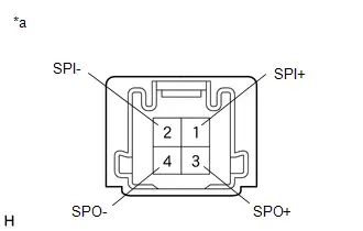
Procedure1
(b) Measure the resistance according to the value(s) in the table below.
Standard Resistance:
| Tester Connection | Condition | Specified Condition | Result |
|---|---|---|---|
| 1 (SPI ) - 3 (SPO ) | Always | Below 1 Ω | Ω |
| 2 (SPI-) - 4 (SPO-) | Always | Below 1 Ω | Ω |
| 1 (SPI ) - 2 (SPI-) | Always | 10 kΩ or higher | kΩ |
| 3 (SPO ) - 4 (SPO-) | Always | 10 kΩ or higher | kΩ |
Post-procedure1
(c) None
| NG |

| REPLACE DCM (TELEMATICS TRANSCEIVER) |
|

| 12. | INSPECT FRONT NO. 3 SPEAKER ASSEMBLY |
HINT:
Click here

| NG |

| REPLACE FRONT NO. 3 SPEAKER ASSEMBLY |
|

| 13. | CLEAR DTC |
(a) Clear the DTCs.
Body Electrical > Navigation System > Clear DTCs
|

| 14. | CHECK FOR DTC |
Pre-procedure1
(a) In accordance with the display of the GTS, perform a speaker circuit energization inspection.
HINT:
Click here

| Tester Display |
|---|
| Speaker Line Electricity Check |
Procedure1
(b) Check for DTCs and proceed to the following step.
Body Electrical > Navigation System > Trouble Codes| Result | Proceed to |
|---|---|
| B1ACA71 is not output | A |
| B1ACA71 is output | B |
Post-procedure1
(c) None
| A |

| END (FRONT NO. 3 SPEAKER ASSEMBLY RH IS DEFECTIVE) |
| B |

| REPLACE STEREO COMPONENT AMPLIFIER ASSEMBLY
|


Front Left Speaker Cable Actuator Stuck (B1ACB71)
DESCRIPTION
This DTC is stored when the stereo component amplifier assembly detects an open in the front speaker LH circuit by energizing the speaker line.
| DTC No. | Detection Item | Trouble Area | DTC Output from | Priority |
|---|---|---|---|---|
| B1ACB71 | Front Left Speaker Cable Actuator Stuck |
| Navigation System | A |
WIRING DIAGRAM
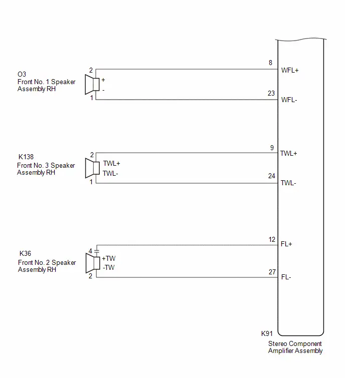
PROCEDURE
| 1. | CHECK PROBLEM SYMPTOM |
(a) Confirm the problem symptoms and proceed to the respective link.
| Result | Proceed to |
|---|---|
| No sound is output from the front No. 1 speaker assembly LH or front No. 3 speaker assembly LH | A |
| No sound is output from the front No. 2 speaker assembly LH | B |
| B |

| GO TO STEP 10 |
|

| 2. | CHECK HARNESS AND CONNECTOR (STEREO COMPONENT AMPLIFIER ASSEMBLY - FRONT NO. 3 SPEAKER ASSEMBLY LH) |
Pre-procedure1
(a) Disconnect the I54 stereo component amplifier assembly connector.
(b) Disconnect the I75 front No. 3 speaker assembly LH connector.
Procedure1
(c) Measure the resistance according to the value(s) in the table below.
Standard Resistance:
| Tester Connection | Condition | Specified Condition | Result |
|---|---|---|---|
| I54-13 (FL ) - I75-4 ( TW) | Always | Below 1 Ω | Ω |
| I54-28 (FL-) - I75-2 (-TW) | Always | Below 1 Ω | Ω |
Post-procedure1
(d) None
| NG |

| REPAIR OR REPLACE HARNESS OR CONNECTOR |
|

| 3. | CHECK HARNESS AND CONNECTOR (FRONT NO. 1 SPEAKER ASSEMBLY LH - FRONT NO. 3 SPEAKER ASSEMBLY LH) |
Pre-procedure1
(a) Disconnect the I75 front No. 3 speaker assembly LH connector.
(b) Disconnect the L1 front No. 1 speaker assembly LH connector.
Procedure1
(c) Measure the resistance according to the value(s) in the table below.
Standard Resistance:
 Click Location & Routing(L1) Click Connector(L1)
 | Tester Connection | Condition | Specified Condition | Result |
|---|---|---|---|
| I75-3 ( ) - L1-2 | Always | Below 1 Ω | Ω |
| I75-1 (-) - L1-1 | Always | Below 1 Ω | Ω |
Post-procedure1
(d) None
| NG |

| REPAIR OR REPLACE HARNESS OR CONNECTOR |
|

| 4. | INSPECT FRONT NO. 1 SPEAKER ASSEMBLY LH |
HINT:
Click here

| NG |

| REPLACE FRONT NO. 1 SPEAKER ASSEMBLY LH |
|

| 5. | CLEAR DTC |
(a) Clear the DTCs.
Body Electrical > Navigation System > Clear DTCs
|

| 6. | CHECK FOR DTC |
Pre-procedure1
(a) In accordance with the display of the GTS, perform a speaker circuit energization inspection.
HINT:
Click here

| Tester Display |
|---|
| Speaker Line Electricity Check |
Procedure1
(b) Check for DTCs and proceed to the following step.
Body Electrical > Navigation System > Trouble Codes| Result | Proceed to |
|---|---|
| B1ACB71 is not output | A |
| B1ACB71 is output | B |
Post-procedure1
(c) None
| A |

| END (FRONT NO. 1 SPEAKER ASSEMBLY RH IS DEFECTIVE) |
|

| 7. | REPLACE FRONT NO. 3 SPEAKER ASSEMBLY LH |
(a) Replace the speaker assembly with a new or known good one.
HINT:
Click here

|

| 8. | CLEAR DTC |
(a) Clear the DTCs.
Body Electrical > Navigation System > Clear DTCs
|

| 9. | CHECK FOR DTC |
Pre-procedure1
(a) In accordance with the display of the GTS, perform a speaker circuit energization inspection.
HINT:
Click here

| Tester Display |
|---|
| Speaker Line Electricity Check |
Procedure1
(b) Check for DTCs and proceed to the following step.
Body Electrical > Navigation System > Trouble Codes| Result | Proceed to |
|---|---|
| B1ACB71 is not output | A |
| B1ACB71 is output | B |
Post-procedure1
(c) None
| A |

| END (FRONT NO. 3 SPEAKER ASSEMBLY LH IS DEFECTIVE) |
| B |

| REPLACE STEREO COMPONENT AMPLIFIER ASSEMBLY
|


| 10. | CHECK HARNESS AND CONNECTOR (STEREO COMPONENT AMPLIFIER ASSEMBLY - FRONT NO. 2 SPEAKER ASSEMBLY LH) |
Pre-procedure1
(a) Disconnect the K91 stereo component amplifier assembly connector.
(b) Disconnect the K36 front no. 2 speaker assembly LH connector.
Procedure1
(c) Measure the resistance according to the value(s) in the table below.
Standard Resistance:
 Click Location & Routing(K91,K36) Click Connector(K91)
 | Tester Connection | Condition | Specified Condition | Result |
|---|---|---|---|
| K91-12 (FL ) - k36-2 ( TW) | Always | Below 1 Ω | Ω |
| K91-27 (FL-) - K36-1 (-TW) | Always | Below 1 Ω | Ω |
Post-procedure1
(d) None
| NG |

| REPAIR OR REPLACE HARNESS OR CONNECTOR |
|

| 11. | REPLACE FRONT NO. 2 SPEAKER ASSEMBLY LH |
(a) Replace the speaker assembly with a new or known good one.
HINT:
Click here

|

| 12. | CLEAR DTC |
(a) Clear the DTCs.
Body Electrical > Navigation System > Clear DTCs
|

| 13. | CHECK FOR DTC |
Pre-procedure1
(a) In accordance with the display of the GTS, perform a speaker circuit energization inspection.
HINT:
Click here

| Tester Display |
|---|
| Speaker Line Electricity Check |
Procedure1
(b) Check for DTCs and proceed to the following step.
Body Electrical > Navigation System > Trouble Codes| Result | Proceed to |
|---|---|
| B1ACB71 is not output | A |
| B1ACB71 is output | B |
Post-procedure1
(c) None
| A |

| END (FRONT NO. 2 SPEAKER ASSEMBLY LH IS DEFECTIVE) |
| B |

| REPLACE STEREO COMPONENT AMPLIFIER ASSEMBLY
|


Rear Door Right Speaker Cable Actuator Stuck (B1ACC71)
DESCRIPTION
This DTC is stored when the stereo component amplifier assembly detects an open in the rear speaker RH circuit by energizing the speaker line.
| DTC No. | Detection Item | DTC Detection Condition | Trouble Area | DTC Output from | Priority |
|---|---|---|---|---|---|
| B1ACC71 | Rear Door Right Speaker Cable Actuator Stuck | Open in the rear speaker RH circuit is detected. (1 trip detection logic) |
| Navigation System | A |
WIRING DIAGRAM
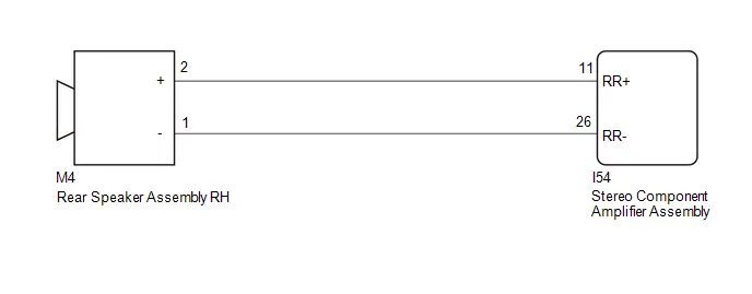
PROCEDURE
| 1. | CHECK HARNESS AND CONNECTOR (STEREO COMPONENT AMPLIFIER ASSEMBLY - REAR SPEAKER ASSEMBLY RH) |
Pre-procedure1
(a) Disconnect the K91 stereo component amplifier assembly connector.
(b) Disconnect the L4 Rear speaker assembly RH connector.
Procedure1
(c) Measure the resistance according to the value(s) in the table below.
Standard Resistance:
 Click Location & Routing(K91,L4) Click Connector(K91) Click Connector(L4)
 | Tester Connection | Condition | Specified Condition | Result |
|---|---|---|---|
| K91-15 (RR ) - L4-2 ( ) | Always | Below 1 Ω | Ω |
| K91-30 (RR-) - L4-1 (-) | Always | Below 1 Ω | Ω |
Post-procedure1
(d) None
| NG |

| REPAIR OR REPLACE HARNESS OR CONNECTOR |
|

| 2. | INSPECT REAR SPEAKER ASSEMBLY RH |
HINT:
Click here

| NG |

| REPLACE REAR SPEAKER ASSEMBLY RH |
|

| 3. | CLEAR DTC |
(a) Clear the DTCs.
Body Electrical > Navigation System > Clear DTCs
|

| 4. | CHECK FOR DTC |
Pre-procedure1
(a) In accordance with the display of the GTS, perform a speaker circuit energization inspection.
HINT:
Click here

| Tester Display |
|---|
| Speaker Line Electricity Check |
Procedure1
(b) Check for DTCs and proceed to the following step.
Body Electrical > Navigation System > Trouble Codes| Result | Proceed to |
|---|---|
| B1ACC71 is not output | A |
| B1ACC71 is output | B |
Post-procedure1
(c) None
| A |

| END (REAR SPEAKER ASSEMBLY RH IS DEFECTIVE) |
| B |

| REPLACE STEREO COMPONENT AMPLIFIER ASSEMBLY
|


Rear Door Left Speaker Cable Actuator Stuck (B1ACD71)
DESCRIPTION
This DTC is stored when the stereo component amplifier assembly detects an open in the rear speaker LH circuit by energizing the speaker line.
| DTC No. | Detection Item | DTC Detection Condition | Trouble Area | DTC Output from | Priority |
|---|---|---|---|---|---|
| B1ACD71 | Rear Door Left Speaker Cable Actuator Stuck | Open in the rear speaker LH circuit is detected. (1 trip detection logic) |
| Navigation System | A |
WIRING DIAGRAM
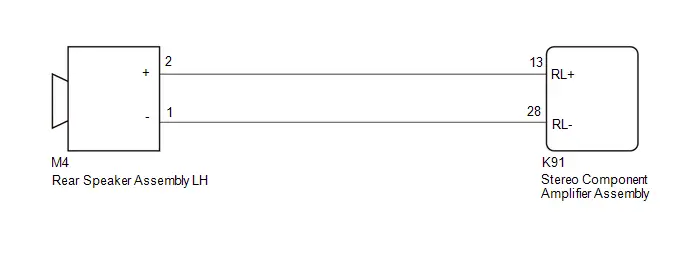
PROCEDURE
| 1. | CHECK HARNESS AND CONNECTOR (STEREO COMPONENT AMPLIFIER ASSEMBLY - REAR SPEAKER ASSEMBLY LH) |
Pre-procedure1
(a) Disconnect the K91 stereo component amplifier assembly connector.
(b) Disconnect the M4 Rear speaker assembly LH connector.
Procedure1
(c) Measure the resistance according to the value(s) in the table below.
Standard Resistance:
 Click Location & Routing(K91,M4) Click Connector(K91) Click Connector(M4)
 | Tester Connection | Condition | Specified Condition | Result |
|---|---|---|---|
| K91-13 (RL ) - M4-2 ( ) | Always | Below 1 Ω | Ω |
| K91-28 (RL-) - M4-1 (-) | Always | Below 1 Ω | Ω |
Post-procedure1
(d) None
| NG |

| REPAIR OR REPLACE HARNESS OR CONNECTOR |
|

| 2. | INSPECT REAR SPEAKER ASSEMBLY LH |
HINT:
Click here

| NG |

| REPLACE REAR SPEAKER ASSEMBLY LH |
|

| 3. | CLEAR DTC |
(a) Clear the DTCs.
Body Electrical > Navigation System > Clear DTCs
|

| 4. | CHECK FOR DTC |
Pre-procedure1
(a) In accordance with the display of the GTS, perform a speaker circuit energization inspection.
HINT:
Click here

| Tester Display |
|---|
| Speaker Line Electricity Check |
Procedure1
(b) Check for DTCs and proceed to the following step.
Body Electrical > Navigation System > Trouble Codes| Result | Proceed to |
|---|---|
| B1ACD71 is not output | A |
| B1ACD71 is output | B |
Post-procedure1
(c) None
| A |

| END (REAR SPEAKER ASSEMBLY LH IS DEFECTIVE) |
| B |

| REPLACE STEREO COMPONENT AMPLIFIER ASSEMBLY
|


Vehicle Speed Signal Circuit Open (B228231)
DESCRIPTION
This DTC is stored when the radio and display receiver assembly detect difference between the GNSS speed and SPD pulse.
| DTC No. | Detection Item | DTC Detection Condition | Trouble Area | DTC Output from | Priority |
|---|---|---|---|---|---|
| B228231 | Toyota Prius Vehicle Speed Signal Circuit Open | When the GNSS position is stable and the vehicle speed is approximately 44 km/h or more, the vehicle speed pulse signal is not detected for 120 seconds or more. (2 trip detection logic) |
| Navigation System | A |
WIRING DIAGRAM
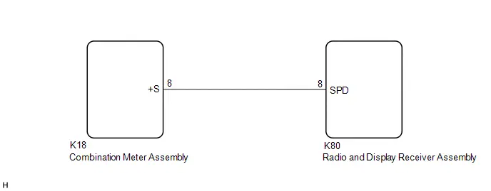
CAUTION / NOTICE / HINT
NOTICE:
Depending on the parts that are replaced during Toyota Prius vehicle inspection or maintenance, performing initialization, registration or calibration may be needed.
Click here

PROCEDURE
| 1. | CHECK Toyota Prius Vehicle CONTROL HISTORY (RoB) |
(a) Check vehicle control history (RoB)
(1) Using the GTS, check for vehicle control history (RoB).
Body Electrical > Navigation System > Utility| Tester Display |
|---|
| Toyota Prius Vehicle Control History (RoB) |
| Result | Proceed to |
|---|---|
| Vehicle control history (RoB) X8023 is output | A |
| Toyota Prius Vehicle control history (RoB) is not output | B |
| B |

| GO TO STEP 4 |
|

| 2. | CHECK OPTIONAL COMPONENTS |
(a) Check that optional components are not installed.
| Result | Proceed to |
|---|---|
| Optional components are installed | A |
| Optional components are not installed | B |
| B |

| GO TO STEP 4 |
|

| 3. | REMOVE OPTIONAL COMPONENTS |
(a) Remove optional components.
(b) Turn the ignition switch off and back to ON.
| NEXT |

| GO TO STEP 4 |
| 4. | CHECK Toyota Prius Vehicle SENSOR (SYSTEM SENSORS CHECK) |
HINT:
For enter diagnostic mode and screen transition, refer to Click here

| (a) Enter diagnostic mode. (1) Enter diagnostic mode. (2) Select "Function Check/Setting" from the "Service Menu" screen. (3) Select "System Sensors Check" from the "Function Check/Setting I" screen. |
|
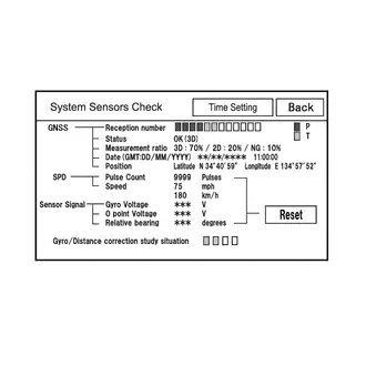
(b) System sensors check
(1) Drive the Toyota Prius vehicle and confirm that the displayed Speed changes in accordance with the vehicle driving condition.
| Result | Proceed to |
|---|---|
| Speed changes | A |
| Speed does not change | B |
| A |

| REPLACE RADIO AND DISPLAY RECEIVER ASSEMBLY |
|

| 5. | CHECK HARNESS AND CONNECTOR (COMBINATION METER ASSEMBLY - RADIO AND DISPLAY RECEIVER ASSEMBLY) |
Pre-procedure1
(a) Disconnect the K18 combination meter assembly connector.
(b) Disconnect the K50 radio and display receiver assembly connector.
Procedure1
(c) Measure the resistance according to the value(s) in the table below.
Standard Resistance:
 Click Location & Routing(K18,K50) Click Connector(K18)
 | Tester Connection | Condition | Specified Condition | Result |
|---|---|---|---|
| K18-8 ( S) - K50-8 (SPD) | Always | Below 1 Ω | Ω |
| K18-8 ( S) or K50-8 (SPD) - Body ground | Always | 10 kΩ or higher | kΩ |
Post-procedure1
(d) None
| OK |

| GO TO METER / GAUGE SYSTEM |
| NG |

| REPAIR OR REPLACE HARNESS OR CONNECTOR |
Rear Camera Image Signal Missing Message (C162287)
DESCRIPTION
This DTC is stored if the radio and display receiver assembly judges that the signal from the rear television camera assembly is not normal.
| DTC No. | Detection Item | DTC Detection Condition | Trouble Area | DTC Output from | Priority |
|---|---|---|---|---|---|
| C162287 | Rear Camera Image Signal Missing Message | When the ignition switch is ON, a malfunction is detected in the image signal of the rear television camera assembly (2 trip detection logic) |
| Navigation System | B |
WIRING DIAGRAM
w/ Back Guide Monitor System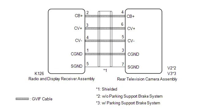 w/ Rear View Monitor System
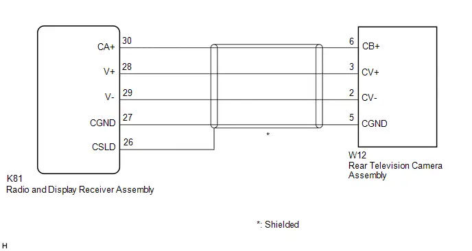
CAUTION / NOTICE / HINT
NOTICE:
Depending on the parts that are replaced during Toyota Prius vehicle inspection or maintenance, performing initialization, registration or calibration may be needed.
Click here

PROCEDURE
| 1. | CHECK MODEL |
(a) Choose the model to be inspected.
| Result | Proceed to |
|---|---|
| w/ Back Guide Monitor System | A |
| w/ Rear View Monitor System | B |
| B |

| GO TO STEP 5 |
|

| 2. | CHECK HARNESS AND CONNECTOR (RADIO AND DISPLAY RECEIVER ASSEMBLY - REAR TELEVISION CAMERA ASSEMBLY) |
Pre-procedure1
(a) Disconnect the K126 radio and display receiver assembly connector.
(b) Disconnect the V2*1 or V3*2 rear television camera assembly connector.
Procedure1
(c) Measure the resistance according to the value(s) in the table below.
Standard Resistance:
 Click Location & Routing(K126) Click Connector(K126)
 | Tester Connection | Condition | Specified Condition | Result |
|---|---|---|---|
| K126-2 (CB ) - V2*1 or V3*2-4 (CB ) | Always | Below 1 Ω | Ω |
| K126-3 (CV ) - V2*1 or V3*2-6 (CV ) | Always | Below 1 Ω | Ω |
| K126-4 (CV-) - V2*1 or V3*2-5 (CV-) | Always | Below 1 Ω | Ω |
| K126-1 (CGND) - V2*1 or V3*2-3 (CGND) | Always | Below 1 Ω | Ω |
| K126-5 (SGND) - Body ground | Always | Below 1 Ω | Ω |
| K126-2 (CB ) or V2*1 or V3*2-4 (CB ) - Body ground | Always | 10 kΩ or higher | kΩ |
| K126-3 (CV ) or V2*1 or V3*2-6 (CV ) - Body ground | Always | 10 kΩ or higher | kΩ |
| K126-4 (CV-) or V2*1 or V3*2-5 (CV-) - Body ground | Always | 10 kΩ or higher | kΩ |
| K126-1 (CGND) or V2*1 or V3*2-3 (CGND) - Body ground | Always | 10 kΩ or higher | kΩ |
- *1: w/o Parking Support Brake System
- *2: w/ Parking Support Brake System
Post-procedure1
(d) None
| NG |

| REPAIR OR REPLACE HARNESS OR CONNECTOR |
|

| 3. | INSPECT RADIO AND DISPLAY RECEIVER ASSEMBLY |
Pre-procedure1
(a) Reconnect the K126 radio and display receiver assembly connector.
Procedure1
| (b) Measure the resistance according to the value(s) in the table below. Standard Resistance:  Click Location & Routing(K126) Click Connector(K126) Click Location & Routing(K126) Click Connector(K126)
|
|
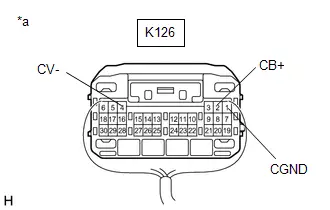
(c) Measure the voltage according to the value(s) in the table below.
Standard Voltage:
 Click Location & Routing(K126) Click Connector(K126)
 | Tester Connection | Condition | Specified Condition | Result |
|---|---|---|---|
| K126-2 (CB ) - K126-1 (CGND) | Power switch on (ACC) | 5.5 to 7.05 V | V |
Post-procedure1
(d) None
| NG |

| REPLACE RADIO AND DISPLAY RECEIVER ASSEMBLY |
|

| 4. | INSPECT REAR TELEVISION CAMERA ASSEMBLY |
(a) Reconnect the V2*1 or V3*2 rear television camera assembly connector.
- *1: w/o Parking Support Brake System
- *2: w/ Parking Support Brake System
(b) Using an oscilloscope, check the waveform of the rear television camera assembly.
HINT:
A waterproof connector is used for the rear television camera assembly. Therefore, inspect the waveform at the radio and display receiver assembly with the connector connected.
OK:
Waveform is similar to that shown in the illustration.
| Item | Content |
|---|---|
| Measurement terminal | K126-3 (CV ) - K126-4 (CV-) |
| Measurement setting | 200 mV/DIV., 50 μs./DIV. |
| Condition | Power switch on (IG), shift lever in R |
HINT:
- The video waveform changes according to the image sent by the rear television camera assembly.
- The video waveform is constantly output when the power switch is turned on (ACC).
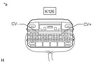
| *a | Component with harness connected (Radio and Display Receiver Assembly) |

| *a | Waveform 1 (camera lens is not covered, displaying an image) |
| *b | Waveform 2 (camera lens is covered, blacking out the screen) |
| *c | Synchronization Signal |
| *d | Video Waveform |
| OK |

| REPLACE RADIO AND DISPLAY RECEIVER ASSEMBLY |
| NG |

| REPLACE REAR TELEVISION CAMERA ASSEMBLY for Wagon: Click here
for Hatchback: Click here
|


| 5. | CHECK HARNESS AND CONNECTOR (RADIO AND DISPLAY RECEIVER ASSEMBLY - REAR TELEVISION CAMERA ASSEMBLY) |
Pre-procedure1
(a) Disconnect the K81 radio and display receiver assembly connector.
(b) Disconnect the O115 rear television camera assembly connector.
Procedure1
(c) Measure the resistance according to the value(s) in the table below.
Standard Resistance:
 Click Location & Routing(K81) Click Connector(K81)
 | Tester Connection | Condition | Specified Condition | Result |
|---|---|---|---|
| K81-30 (CA ) - O115-6 (CB ) | Always | Below 1 Ω | Ω |
| K81-28 (V ) - O115-3 (CV ) | Always | Below 1 Ω | Ω |
| K81-29 (V-) - O115-2 (CV-) | Always | Below 1 Ω | Ω |
| K81-27 (CGND) - O115-5 (CGND) | Always | Below 1 Ω | Ω |
| K81-30 (CA ) or O115-6 (CB ) - Body ground | Always | 10 kΩ or higher | kΩ |
| K81-28 (V ) or O115-3 (CV ) - Body ground | Always | 10 kΩ or higher | kΩ |
| K81-29 (V-) or O115-2 (CV-) - Body ground | Always | 10 kΩ or higher | kΩ |
| K81-27 (CGND) or O115-5 (CGND) - Body ground | Always | 10 kΩ or higher | kΩ |
Post-procedure1
(d) None
| NG |

| REPAIR OR REPLACE HARNESS OR CONNECTOR |
|

| 6. | INSPECT RADIO AND DISPLAY RECEIVER ASSEMBLY |
Pre-procedure1
(a) Reconnect the K81 radio and display receiver assembly connector.
Procedure1
| (b) Measure the resistance according to the value(s) in the table below. Standard Resistance:  Click Location & Routing(K81) Click Connector(K81) Click Location & Routing(K81) Click Connector(K81)
|
|
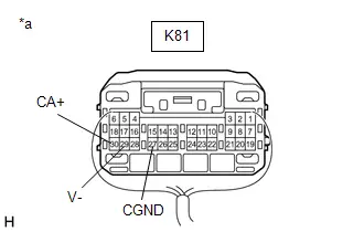
(c) Measure the voltage according to the value(s) in the table below.
Standard Voltage:
 Click Location & Routing(K81) Click Connector(K81)
 | Tester Connection | Condition | Specified Condition | Result |
|---|---|---|---|
| K81-30 (CA ) - K81-27 (CGND) | Power switch on (ACC) | 5.5 to 7.05 V | V |
Post-procedure1
(d) None
| NG |

| REPLACE RADIO AND DISPLAY RECEIVER ASSEMBLY |
|

| 7. | INSPECT REAR TELEVISION CAMERA ASSEMBLY |
(a) Reconnect the W12 rear television camera assembly connector.
(b) Using an oscilloscope, check the waveform of the rear television camera assembly.
HINT:
A waterproof connector is used for the rear television camera assembly. Therefore, inspect the waveform at the radio and display receiver assembly with the connector connected.
OK:
Waveform is similar to that shown in the illustration.
| Item | Content |
|---|---|
| Measurement terminal | K81-28 (V ) - K81-29 (V-) |
| Measurement setting | 200 mV/DIV., 50 μs./DIV. |
| Condition | Power switch on (IG), shift lever in R |
HINT:
- The video waveform changes according to the image sent by the rear television camera assembly.
- The video waveform is constantly output when the power switch is turned on (ACC).
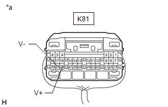
| *a | Component with harness connected (Radio and Display Receiver Assembly) |

| *a | Waveform 1 (camera lens is not covered, displaying an image) |
| *b | Waveform 2 (camera lens is covered, blacking out the screen) |
| *c | Synchronization Signal |
| *d | Video Waveform |
| OK |

| REPLACE RADIO AND DISPLAY RECEIVER ASSEMBLY |
| NG |

| REPLACE REAR TELEVISION CAMERA ASSEMBLY |
Lost Communication With ECM/PCM "A" Missing Message (U010087,U012987,U014087,U015587,U016487,U016887,U019887,U023B87,U026587,U029387,U100049,U111087)
DESCRIPTION
These DTCs are stored when the radio and display receiver assembly detects a malfunction in the CAN communication circuit.
| DTC No. | Detection Item | DTC Detection Condition | Trouble Area | DTC Output from | Priority |
|---|---|---|---|---|---|
| U010087 | Lost Communication With ECM/PCM "A" Missing Message | Communication malfunction between radio and display receiver assembly and Engine/EV ECU for 12 seconds or more | CAN communication system | Navigation System | B |
| U012987 | Lost Communication With Brake System Control Module Missing Message | Communication malfunction between radio and display receiver assembly and No. 2 skid control ECU (brake actuator assembly) for 11 seconds or more (2 trip detection logic) | CAN communication system | Navigation System | B |
| U014087 | Lost Communication with Body Control Module Missing Message | Communication malfunction between radio and display receiver assembly and main body ECU (multiplex network body ECU) for 11 seconds or more (2 trip detection logic) | CAN communication system | Navigation System | B |
| U015587 | Lost Communication with Instrument Panel Cluster (IPC) Control Module Missing Message | Communication malfunction between radio and display receiver assembly and combination meter assembly for 31 seconds or more | CAN communication system | Navigation System | B |
| U016487 | Lost Communication with HVAC Control Module Missing Message | Communication malfunction between radio and display receiver assembly and air conditioning amplifier assembly for 10 seconds or more (2 trip detection logic) | CAN communication system | Navigation System | B |
| U016887 | Lost Communication with Toyota Prius Vehicle Security Control Module Missing Message | Communication malfunction between radio and display receiver assembly and certification ECU (smart key ECU assembly) for 11 seconds or more (2 trip detection logic) | CAN communication system | Navigation System | B |
| U019887 | Lost Communication with Telematic Control Module "A" Missing Message | Communication malfunction between radio and display receiver assembly and telematics transceiver for 3 seconds or more (2 trip detection logic) | CAN communication system | Navigation System | B |
| U029387 | Lost Communication with Hybrid/EV Powertrain Control Module Missing Message | Communication malfunction between radio and display receiver assembly and hybrid Toyota Prius vehicle control ECU for 11 seconds or more (2 trip detection logic) | CAN communication system | Navigation System | B |
| U100049 | CAN Register Fixing Internal Electronic Failure |
(2 trip detection logic) |
| Navigation System | B |
| U111087 | Lost Communication with Clearance Sonar Module | Communication malfunction between radio and display receiver assembly and clearance warning ECU assembly for 11 seconds or more (2 trip detection logic) | CAN communication system | Navigation System | B |
PROCEDURE
| 1. | CLEAR DTC |
(a) Clear the DTCs.
Body Electrical > Navigation System > Clear DTCs
|

| 2. | CHECK FOR DTC |
Pre-procedure1
(a) Turn the ignition switch off.
(b) Turn the ignition switch to ON and wait for 45 seconds or more.
Procedure1
(c) Check for DTCs.
Body Electrical > Navigation System > Trouble Codes| Result | Proceed to |
|---|---|
| DTCs are not output | A |
| U010087, U012987, U014087, U015587, U016487, U016887, U019887, U029387, U100049 or U111087 is output | B |
| U100049 is output | C |
Post-procedure1
(d) None
| A |

| GO TO HOW TO PROCEED WITH TROUBLESHOOTING |
| B |

| GO TO CAN COMMUNICATION SYSTEM |
| C |

| REPLACE RADIO AND DISPLAY RECEIVER ASSEMBLY |
Lost Local Communication with MET Missing Message (U11D087)
DESCRIPTION
These DTCs are stored when the radio and display receiver assembly detects a communication malfunction with the combination meter assembly.
| DTC No. | Detection Item | DTC Detection Condition | Trouble Area | DTC Output from | Priority |
|---|---|---|---|---|---|
| U11D087 | Lost Local Communication with MET Missing Message | Communication malfunction between radio and display receiver assembly and combination meter assembly for 30 seconds or more (2 trip detection logic) |
| Navigation System | A |
WIRING DIAGRAM
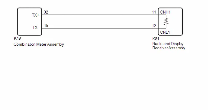
CAUTION / NOTICE / HINT
NOTICE:
-
Depending on the parts that are replaced during Toyota Prius vehicle inspection or maintenance, performing initialization, registration or calibration may be needed.
Click here

- Inspect the fuses for circuits related to this system before performing the following procedure.
- When replacing the combination meter assembly, make sure to replace it with a new one. If a combination meter assembly which was installed to another Toyota Prius vehicle is used, the information stored in the combination meter assembly will not match the information from the vehicle and a DTC may be stored.
- Before measuring the resistance of the CAN bus, turn the ignition switch off and leave the vehicle for 1 minute or more without operating the key, switches or opening or closing the doors. After that, disconnect the cable from the negative (-) battery terminal and leave the Toyota Prius vehicle for 1 minute or more before measuring the resistance.
-
After turning the ignition switch off, waiting time may be required before disconnecting the cable from the negative (-) battery terminal. Therefore make sure to read the disconnecting the cable from the negative (-) battery terminal notices before proceeding with work.
Click here

HINT:
- Before disconnecting related connectors for inspection, push in on the connector body to check that each connector is not loose or disconnected.
- When a connector is disconnected, check that the terminals and connector body are not cracked, deformed or corroded.
-
When the cable is disconnected / reconnected to the battery terminal, systems temporarily stop operating. However, each system has a function that completes learning the first time the system is used.
Click here

PROCEDURE
| 1. | CHECK FOR CAN BUS WIRE (COMBINATION METER ASSEMBLY MAIN WIRE) |
Pre-procedure1
(a) Disconnect the cable from the negative (-) battery terminal.
(b) Disconnect the K19 combination meter assembly connector.
Procedure1
(c) Measure the resistance according to the value(s) in the table below.
Standard Resistance:
 Click Location & Routing(K19,K8) Click Connector(K19) Click Connector(K8)
 | Tester Connection | Condition | Specified Condition | Result |
|---|---|---|---|
| K19-32 (TX ) - K19-15 (TX-) | Cable disconnected from negative (-) battery terminal | 108 to 132 Ω | Ω |
| K19-32 (TX ) - K8-4 (CG) | Cable disconnected from negative (-) battery terminal | 200 Ω or higher | Ω |
| K19-15 (TX-) - K8-4 (CG) | Cable disconnected from negative (-) battery terminal | 200 Ω or higher | Ω |
| K19-32 (TX ) - K8-16 (BAT) | Cable disconnected from negative (-) battery terminal | 6 kΩ or higher | kΩ |
| K19-15 (TX-) - K8-16 (BAT) | Cable disconnected from negative (-) battery terminal | 6 kΩ or higher | kΩ |
Post-procedure1
(d) None
| OK |

| REPLACE COMBINATION METER ASSEMBLY |
|

| 2. | CHECK FOR CAN BUS WIRE (RADIO AND DISPLAY RECEIVER ASSEMBLY MAIN WIRE) |
Pre-procedure1
(a) Disconnect the cable from the negative (-) battery terminal.
(b) Disconnect the K81 radio and display receiver assembly connector.
Procedure1
(c) Measure the resistance according to the value(s) in the table below.
Standard Resistance:
 Click Location & Routing(K81,K8) Click Connector(K81) Click Connector(K8)
 | Tester Connection | Condition | Specified Condition | Result |
|---|---|---|---|
| K81-11 (CNH1) - K81-12 (CNL1) | Cable disconnected from negative (-) battery terminal | 108 to 132 Ω | Ω |
| K81-11 (CNH1) - K8-4 (CG) | Cable disconnected from negative (-) battery terminal | 200 Ω or higher | Ω |
| K81-12 (CNL1) - K8-4 (CG) | Cable disconnected from negative (-) battery terminal | 200 Ω or higher | Ω |
| K81-11 (CNH1) - K8-16 (BAT) | Cable disconnected from negative (-) battery terminal | 6 kΩ or higher | kΩ |
| K81-12 (CNL1) - K8-16 (BAT) | Cable disconnected from negative (-) battery terminal | 6 kΩ or higher | kΩ |
Post-procedure1
(d) None
| OK |

| REPLACE RADIO AND DISPLAY RECEIVER ASSEMBLY |
| NG |

| REPAIR OR REPLACE HARNESS OR CONNECTOR |
Satellite Radio Broadcast cannot be Received
WIRING DIAGRAM
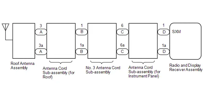
CAUTION / NOTICE / HINT
NOTICE:
Some satellite radio broadcasts require payment. A contract must be made between a satellite radio company and the user. If the contract expires, it will not be possible to listen to the broadcast.
HINT:
Depending on the parts that are replaced during Toyota Prius vehicle inspection or maintenance, performing initialization, registration or calibration may be needed. Refer to Precaution for Audio and Visual System.
Click here

PROCEDURE
| 1. | CHECK SURROUNDINGS |
(a) Check if the Toyota Prius vehicle is in an environment where reception is difficult due to something blocking the area above the vehicle.
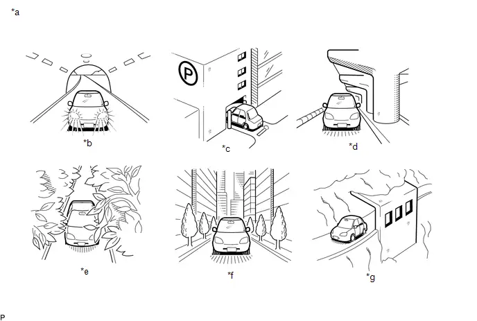
| *a | Example | *b | In a tunnel |
| *c | In a building | *d | Under an overpass |
| *e | In a forest or on tree-lined path | *f | Between tall buildings |
| *g | Under a cliff or overhang | - | - |
HINT:
If the area above the Toyota Prius vehicle is blocked, such as when in a building or tunnel, reception may not be possible.
OK:
Area above vehicle is not blocked.
| NG |

| END (MOVE VEHICLE TO LOCATION WHERE RECEPTION IS BETTER) |
|

| 2. | CHECK RADIO AND DISPLAY RECEIVER ASSEMBLY |
(a) Check if CH001 (free broadcast) can be received.
OK:
CH001 can be received.
| NG |

| GO TO STEP 6 |
|

| 3. | CHECK DISPLAY SETTING |
(a) Check the display screen.
| Result | Proceed to |
|---|---|
| "SAT Ch Unauth" is displayed. | A |
| "-----" is displayed. | B |
| None of the displays above are shown. | C |
| B |

| THERE IS NO SONG/PROGRAM TITLE OR ARTIST NAME/FEATURE ASSOCIATED WITH CHANNEL AT THAT TIME |
| C |

| GO TO STEP 6 |
|

| 4. | CHECK CONTRACT CONDITIONS |
(a) Check if the pay-type contract has been extended, or if the contract period has ended.
OK:
Pay-type contract is valid.
| NG |

| TO RECEIVE PAY-TYPE BROADCASTS, CONTRACT MUST BE MADE WITH SATELLITE RADIO COMPANY |
|

| 5. | PERFORM ACTIVATION REFRESH |
(a) Perform activation refresh by referring to the satellite radio company website (http://www.siriusxm.com).
OK:
Malfunction disappears.
HINT:
The SiriusXM radio ID that is necessary to perform activation refresh is displayed when CH000 is selected on the satellite radio.
| OK |

| END |
| NG |

| PROCEED TO NEXT SUSPECTED AREA SHOWN IN PROBLEM SYMPTOMS TABLE
|


| 6. | CHECK DISPLAY |
(a) Check the display screen.
| Result | Proceed to |
|---|---|
| "SAT Ck Antenna" is displayed. | A |
| "SAT No Signal" is displayed. | B |
| "Loading" is displayed. | |
| "SAT Ch Off Air" is displayed. | C |
| After "SAT Ch Unavail" is displayed, display automatically switches to CH001. | D |
| None of the displays above are shown. | E |
| B |

| END (MOVE Toyota Prius Vehicle TO LOCATION WHERE RECEPTION IS BETTER) |
| C |

| CHANNEL IS CURRENTLY NOT BEING BROADCASTED. BROADCAST CAN BE LISTENED TO OR VIEWED WHEN IT IS BACK ON AIR. (CHECK WITH RADIO STATION) |
| D |

| CHANNEL BROADCAST HAS ENDED (CHECK WITH RADIO STATION) |
| E |

| GO TO STEP 11 |
|

| 7. | CHECK ANTENNA CORD SUB-ASSEMBLY (for Roof) |
Click here

| NG |

| REPLACE ANTENNA CORD SUB-ASSEMBLY (for Roof)
|


|

| 8. | CHECK NO. 3 ANTENNA CORD SUB-ASSEMBLY |
Click here

| NG |

| REPLACE ANTENNA CORD SUB-ASSEMBLY (for Type A)
|


|

| 9. | CHECK ANTENNA CORD SUB-ASSEMBLY (for Instrument Panel) |
Click here

| NG |

| REPLACE ANTENNA CORD SUB-ASSEMBLY (for Instrument Panel)
|


|

| 10. | REPLACE ROOF ANTENNA ASSEMBLY |
(a) Replace the roof antenna assembly with a new or known good one.
Click here


(b) Clear the DTCs.
Body Electrical > Navigation System > Trouble Codes(c) Check for DTCs.
Body Electrical > Navigation System > Trouble CodesOK:
No DTCs are output.
| OK |

| END (NO. 1 AMPLIFIER ANTENNA ASSEMBLY IS DEFECTIVE) |
| NG |

| PROCEED TO NEXT SUSPECTED AREA SHOWN IN PROBLEM SYMPTOMS TABLE
|


| 11. | CHECK CURRENTLY SELECTED CHANNEL |
(a) Check if CH000 is currently selected.
OK:
CH000 is selected.
| OK |

| END (CH000 HAS NO SOUND. SELECT ANOTHER CHANNEL.) |
| NG |

| PROCEED TO NEXT SUSPECTED AREA SHOWN IN PROBLEM SYMPTOMS TABLE
|


Satellite Radio Broadcast cannot be Selected or After Selecting Broadcast, Broadcast cannot be Added into Memory
CAUTION / NOTICE / HINT
NOTICE:
Some satellite radio broadcasts require payment. A contract must be made between a satellite radio company and the user. If the contract expires, it will not be possible to listen to the broadcast.
PROCEDURE
| 1. | CHECK RADIO AND DISPLAY RECEIVER ASSEMBLY |
(a) Check radio condition.
OK:
Broadcast cannot be selected
| Result | Proceed to |
|---|---|
| Broadcast cannot be selected. | OK |
| Broadcast cannot be selected, but selection cannot be memorized. | NG |
| OK |

| ADD PRESET CHANNEL INTO MEMORY AGAIN |
|

| 2. | CHECK RADIO AND DISPLAY RECEIVER ASSEMBLY |
(a) Check the number of preset channels.
OK:
36 channels have already been preset.
| OK |

| END (ONLY 36 CHANNELS CAN BE PRESET) |
|

| 3. | CHECK AUXILIARY BATTERY |
(a) Check if the auxiliary battery was replaced.
OK:
Auxiliary Battery was not replaced.
| OK |

| REPLACE RADIO AND DISPLAY RECEIVER ASSEMBLY |
|

| 4. | ADD PRESET CHANNEL INTO MEMORY AGAIN |
(a) Check if the preset channels that have been cleared can be added into memory again.
OK:
Preset channels can be added into memory.
| OK |

| END |
| NG |

| PROCEED TO NEXT SUSPECTED AREA SHOWN IN PROBLEM SYMPTOMS TABLE
|


Radio Broadcast cannot be Received or Poor Reception
CAUTION / NOTICE / HINT
HINT:
Depending on the parts that are replaced during vehicle inspection or maintenance, performing initialization, registration or calibration may be needed. Refer to Precaution for Audio and Visual System.
Click here

PROCEDURE
| 1. | CHECK RADIO AND DISPLAY RECEIVER ASSEMBLY |
(a) Check the radio automatic station search function by activating it.
OK:
Automatic station search function stops on a station.
| OK |

| USE SIMULATION METHOD TO CHECK |
|

| 2. | CHECK OPTIONAL COMPONENTS |
(a) Check if any optional components that may decrease reception capacity, such as sunshade film or a telephone antenna, are installed.
OK:
Optional components are not installed.
NOTICE:
Do not remove optional components without the permission of the customer.
| NG |

| REMOVE OPTIONAL COMPONENTS AND CHECK AGAIN (SEE NOTICE ABOVE) |
|

| 3. | CHECK RADIO AND DISPLAY RECEIVER ASSEMBLY |
| (a) Preparation for check (1) Disconnect the RA radio and display receiver assembly connector. |
|
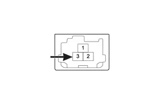
(b) Check for noise
(1) Turn the ignition switch to ON with the radio and display receiver assembly connector connected.
(2) Turn the radio and display receiver assembly on and tune into AM mode.
(3) Place a screwdriver, thin wire or other metal object on the radio and display receiver assembly antenna jack and check that noise can be heard from the speakers.
OK:
Noise can be heard from the speakers.
| NG |

| REPLACE RADIO AND DISPLAY RECEIVER ASSEMBLY |
|

| 4. | INSPECT RADIO AND DISPLAY RECEIVER ASSEMBLY |
(a) Disconnect the RA radio and display receiver assembly connector.
| (b) Measure the voltage according to the value(s) in the table below. Standard Voltage:
|
|
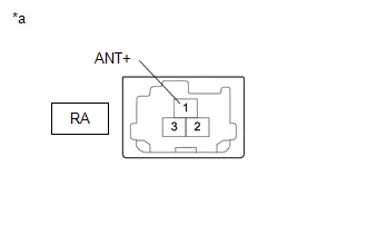
| NG |

| REPLACE RADIO AND DISPLAY RECEIVER ASSEMBLY |
|

| 5. | INSPECT ANTENNA CORD SUB-ASSEMBLY (for Instrument Panel) |
(a) Replace the antenna cord sub-assembly with a new or known good one and check if radio broadcasts can be received normally.
Click here


OK:
Radio broadcasts can be received normally.
| OK |

| END |
|

| 6. | INSPECT NO. 3 ANTENNA CORD SUB-ASSEMBLY |
(a) Replace the No. 3 antenna cord sub-assembly with a new or known good one and check if radio broadcasts can be received normally.
Click here


OK:
Radio broadcasts can be received normally.
| OK |

| END |
|

| 7. | INSPECT ANTENNA CORD SUB-ASSEMBLY (for Roof) |
(a) Replace the No. 2 antenna cord sub-assembly with a new or known good one and check if radio broadcasts can be received normally.
Click here


OK:
Radio broadcasts can be received normally.
| OK |

| END |
|

| 8. | INSPECT ROOF ANTENNA ASSEMBLY |
(a) Replace the roof antenna assembly with a new or known good one and check if radio broadcasts can be received normally.
Click here


OK:
Radio broadcasts can be received normally.
| OK |

| END |
| NG |

| REPLACE RADIO AND DISPLAY RECEIVER ASSEMBLY |
Cellular Phone Registration Failure
CAUTION / NOTICE / HINT
HINT:
Depending on the parts that are replaced during vehicle inspection or maintenance, performing initialization, registration or calibration may be needed. Refer to Precaution for Audio and Visual System.
Click here

PROCEDURE
| 1. | CHECK USAGE CONDITION |
(a) Check that the Toyota Prius vehicle and cellular phone meet the following conditions:
NOTICE:
If changing cellular phone settings, updating software, etc. is necessary, make sure to obtain the permission of the customer first.
- The operation of the cellular phone has been confirmed
- The "Bluetooth" setting of the cellular phone is set to on
- The Wi-Fi setting of the cellular phone is set to off
- The operating system and software of the "Bluetooth" device are the latest versions
- There are no other radio wave emitting devices (Wi-Fi communication device, etc., which emit radio waves in the 2.4 GHz frequency band) inside the Toyota Prius vehicle.
(b) Register the cellular phone again and check if it is registered correctly.
HINT:
If operation of the cellular phone or radio and display receiver assembly is requested, make sure to follow the instructions closely and perform the operation.
| Result | Proceed to |
|---|---|
| Cellular phone can be registered. | A |
| Cellular phone cannot be registered. | B |
| A |

| END |
|

| 2. | RESTART CELLULAR PHONE |
(a) Restart the cellular phone.
(b) Turn the ignition switch off.
(c) Turn the ignition switch to ACC.
(d) Register the cellular phone as a connected device again and check if it is registered correctly.
HINT:
If operation of the cellular phone or radio and display receiver assembly is requested, make sure to follow the instructions closely and perform the operation.
| Result | Proceed to |
|---|---|
| Cellular phone can be registered. | A |
| Cellular phone cannot be registered. | B |
| A |

| END |
|

| 3. | MOVE CELLULAR PHONE |
(a) Move the cellular phone close to the in-Toyota Prius vehicle device.
(b) Perform the registration procedure for the cellular phone again and check that it registers correctly.
HINT:
If operation of the cellular phone or radio and display receiver assembly is requested, make sure to follow the instructions closely and perform the operation.
| Result | Proceed to |
|---|---|
| Cellular phone can be registered. | A |
| Cellular phone cannot be registered. | B |
| A |

| END |
|

| 4. | CLEAR REGISTERED DEVICE INFORMATION |
(a) Clear all "Bluetooth" devices registered to the cellular phone and in-Toyota Prius vehicle device.
(b) Register the cellular phone as a connected device again and check if it is registered correctly.
HINT:
If operation of the cellular phone or radio and display receiver assembly is requested, make sure to follow the instructions closely and perform the operation.
| Result | Proceed to |
|---|---|
| Cellular phone can be registered. | A |
| Cellular phone cannot be registered. | B |
| A |

| END |
|

| 5. | OPERATION USING OTHER Toyota Prius Vehicle |
(a) Using another vehicle, perform the registration procedure for the cellular phone again and check that it registers correctly.
HINT:
- Make sure to obtain the permission of the customer first.
- After the inspection, clear the registered information and usage history acquired during the inspection.
- If operation of the cellular phone or radio and display receiver assembly is requested, make sure to follow the instructions closely and perform the operation.
| Result | Proceed to |
|---|---|
| Cellular phone can be registered. | A |
| Cellular phone cannot be registered. | B |
| A |

| END |
|

| 6. | REPLACE CELLULAR PHONE |
(a) Using another "Bluetooth" compatible cellular phone, perform the registration procedure and check that it registers correctly.
HINT:
- Make sure to obtain the permission of the customer first.
- After the inspection, clear the registered information and usage history acquired during the inspection.
- If operation of the cellular phone or radio and display receiver assembly is requested, make sure to follow the instructions closely and perform the operation.
| Result | Proceed to |
|---|---|
| Cellular phone can be registered. | A |
| Cellular phone cannot be registered. | B |
| A |

| CELLULAR PHONE MALFUNCTION (CHECK CUSTOMER`S CELLULAR PHONE) |
| B |

| REPLACE RADIO AND DISPLAY RECEIVER ASSEMBLY |
Cellular Phone Inspection
PROCEDURE
| 1. | CHECK USAGE CONDITION |
(a) Check that the vehicle and cellular phone meet the following conditions:
NOTICE:
If changing cellular phone settings, updating software, etc. is necessary, make sure to obtain the permission of the customer first.
- The operation of the cellular phone has been confirmed
- The cellular phone is registered as a hands-free device
- The "Bluetooth" setting of the cellular phone is set to on
- The Wi-Fi setting of the cellular phone is set to off
- The operating system and software of the "Bluetooth" device are the latest versions
- There are no other radio wave emitting devices (Wi-Fi communication device, etc., which emit radio waves in the 2.4 GHz frequency band) inside the Toyota Prius vehicle.
- Check for malfunctions and confirm that the device operates correctly.
HINT:
If operation of the cellular phone or multi-media module receiver assembly is requested, make sure to follow the instructions closely and perform the operation.
| Result | Proceed to |
|---|---|
| Malfunction does not occur | A |
| Malfunction occurs | B |
| A |

| END |
|

| 2. | RESTART |
(a) Turn off the cellular phone and then turn it on again.
(b) Turn the ignition switch off and then turn it to ON again.
(c) Check for malfunctions and confirm that the device operates correctly.
HINT:
If operation of the cellular phone or radio and display receiver assembly is requested, make sure to follow the instructions closely and perform the operation.
| Result | Proceed to |
|---|---|
| Malfunction does not occur | A |
| Malfunction occurs | B |
| A |

| END |
|

| 3. | CHECK OPERATION |
(a) Check if the in-Toyota Prius vehicle device can be detected by the cellular phone.
HINT:
If operation of the cellular phone or radio and display receiver assembly is requested, make sure to follow the instructions closely and perform the operation.
| Result | Proceed to |
|---|---|
| In-Toyota Prius vehicle device can be detected | A |
| In-vehicle device cannot be detected | B |
| B |

| GO TO STEP 5 |
|

| 4. | REREGISTRATION |
(a) Clear registered information of any cellular phone or in-Toyota Prius vehicle device which is causing a malfunction of the cellular phone/in-vehicle device.
(b) Register the cellular phone again.
(c) Check for malfunctions and confirm that the device operates correctly.
HINT:
If operation of the cellular phone or radio and display receiver assembly is requested, make sure to follow the instructions closely and perform the operation.
| Result | Proceed to |
|---|---|
| Malfunction does not occur | A |
| Malfunction occurs | B |
| A |

| END |
|

| 5. | CHECK OPERATION USING OTHER Toyota Prius Vehicle |
(a) Check if the customers cellular phone functions normally using another vehicle.
HINT:
- Make sure to obtain the permission of the customer first.
- After the inspection, clear the registered information and usage history acquired during the inspection.
- If operation of the cellular phone or radio and display receiver assembly is requested, make sure to follow the instructions closely and perform the operation.
| Result | Proceed to |
|---|---|
| Malfunction does not occur | A |
| Malfunction occurs | B |
| A |

| GO TO PROBLEM SYMPTOMS TABLE
|


|

| 6. | REPLACE CELLULAR PHONE |
(a) Register another "Bluetooth" compatible cellular phone.
HINT:
Make sure to obtain the permission of the customer first.
(b) Using another "Bluetooth" compatible cellular phone, check for malfunctions and confirm that the device operates correctly.
HINT:
- After the inspection, clear the registered information and usage history acquired during the inspection.
- If operation of the cellular phone or radio and display receiver assembly is requested, make sure to follow the instructions closely and perform the operation.
| Result | Proceed to |
|---|---|
| Malfunction does not occur | A |
| Malfunction occurs | B |
| A |

| CELLULAR PHONE MALFUNCTION (CHECK CUSTOMERS CELLULAR PHONE) |
| B |

| GO TO PROBLEM SYMPTOMS TABLE
|


USB Audio System Recognition/Play Error
WIRING DIAGRAM
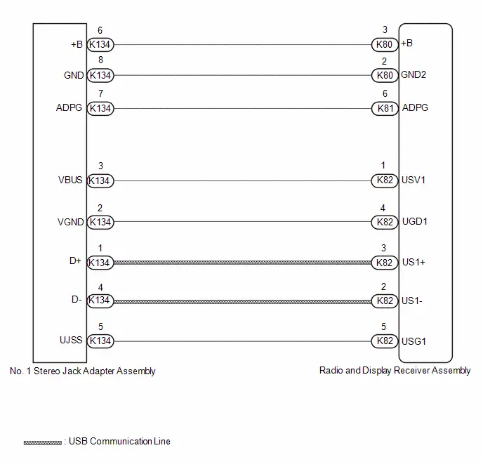
CAUTION / NOTICE / HINT
NOTICE:
Depending on the parts that are replaced during vehicle inspection or maintenance, performing initialization, registration or calibration may be needed.
Click here

HINT:
- When many folders or files exist in the USB storage device, it may take a while to begin playback.
- When using a USB storage device, files that are protected by copyright or encrypted cannot be played
- If a USB hub is being used, remove it.
-
When files on the USB storage device are not played in the sorted order, perform the following procedure.
- Assign a number to the start of each file name.
- Move the files to a folder and copy each folder to the USB storage device.
PROCEDURE
| 1. | CHECK USB STORAGE DEVICE OR "iPod" |
(a) Disconnect the USB storage device or "iPod" from the No. 1 stereo jack adapter assembly.
(b) Check that playable files exist in the USB storage device or "iPod".
(c) Check that the USB storage device or "iPod" being used by the customer is a compatible version and format.
| Result | Proceed to |
|---|---|
| The format of the USB storage device is compatible The version of the "iPod" is compatible | A |
| Playable files do not exist The format of the USB storage device is not compatible The version of the "iPod" is not compatible | B |
| B |

| END |
|

| 2. | CHECK HARNESS AND CONNECTOR (RADIO AND DISPLAY RECEIVER ASSEMBLY - NO. 1 STEREO JACK ADAPTER ASSEMBLY) |
(a) Disconnect the K82 radio and display receiver assembly connector.
(b) Disconnect the K134 No. 1 stereo jack adapter assembly connector.
| (c) Measure the resistance according to the value(s) in the table below. Standard Resistance:  Click Location & Routing(K82,K134) Click Connector(K82) Click Connector(K134) Click Location & Routing(K82,K134) Click Connector(K82) Click Connector(K134)
|
|
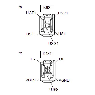
| NG |

| REPAIR OR REPLACE HARNESS OR CONNECTOR |
|

| 3. | INSPECT RADIO AND DISPLAY RECEIVER ASSEMBLY (USV1, B) |
(a) Disconnect the K134 No. 1 stereo jack adapter assembly connector.
(b) Measure the voltage according to the value(s) in the table below.
Standard Voltage:
 Click Location & Routing(K134) Click Connector(K134)
 | Tester Connection | Condition | Specified Condition |
|---|---|---|
| K134-3 (VBUS) - K134-2 (VGND) | Ignition switch ON | 4.5 to 5.5 V |
| K134-6 ( B) - K134-8 (GND) | Always | 11 to 14 V |
HINT:
Measure the voltage with the radio and display receiver assembly connectors connected.
| NG |

| REPLACE RADIO AND DISPLAY RECEIVER ASSEMBLY |
|

| 4. | FORMAT USB DEVICE OR INITIALIZE "iPod" AND RECHECK |
(a) Format the USB storage device or initialize the "iPod" to delete the audio files.
NOTICE:
When formatting the USB storage device or initializing the "iPod", all audio files stored in the device will be deleted. Make sure to back up the audio files before performing this procedure.
(b) Restore the data and check if the problem can be reproduced.
| Result | Proceed to |
|---|---|
| Malfunction disappears | A |
| Malfunction occurs. | B |
| A |

| END |
|

| 5. | CHECK USB STORAGE DEVICE OR "iPod'" |
(a) Disconnect the USB storage device or "iPod" from the No. 1 stereo jack adapter assembly.
(b) Turn the ignition switch from off to ON
HINT:
If another USB storage device or "iPod" is to be connected, it is necessary to turn the ignition switch off in order for the device to be detected.
(c) Connect a known good USB storage device or "iPod" to the No. 1 stereo jack adapter assembly.
HINT:
- When a USB storage device is used, replace it with another device and perform the inspection.
- When an "iPod" is used, replace it with another device and perform the inspection.
(d) Perform the operation again and check if the problem symptom recurs.
| Result | Proceed to |
|---|---|
| Malfunction disappears | A |
| Malfunction occurs | B |
| A |

| END |
|

| 6. | CHECK NO. 1 STEREO JACK ADAPTER ASSEMBLY |
(a) Replace the No.1 stereo jack adapter assembly with a new or known good one.
Click here

(b) Check if the problem symptom recurs.
| Result | Proceed to |
|---|---|
| Malfunction disappears | A |
| Malfunction occurs | B |
| A |

| END (NO. 1 STEREO JACK ADAPTER ASSEMBLY MALFUNCTION) |
| B |

| REPLACE RADIO AND DISPLAY RECEIVER ASSEMBLY |
Speaker Circuit
DESCRIPTION
If there is a short in a speaker circuit, the radio and display receiver assembly detects it and stops output to the speakers.
As a result, sound cannot be heard from the speakers even if there is no malfunction in the radio and display receiver assembly or speakers.
WIRING DIAGRAM

CAUTION / NOTICE / HINT
NOTICE:
-
Depending on the parts that are replaced during Toyota Prius vehicle inspection or maintenance, performing initialization, registration or calibration may be needed. Refer to Precaution for Audio and Visual System.
Click here

PROCEDURE
| 1. | CHECK MODEL |
(a) Choose the model to be inspected.
| Result | Proceed to |
|---|---|
| w/ DCM (Telematics Transceiver) | A |
| w/o DCM (Telematics Transceiver) | B |
| B |

| GO TO STEP 9 |
|

| 2. | CHECK SPEAKER (OPERATION CHECK) |
| (a) Enter diagnostic mode. Click here
|
|

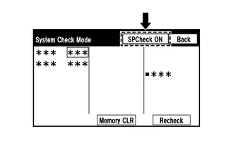
(b) Select "Failure Diagnosis" from the "Service Menu" screen.
(c) Select "System Check" from the "Failure Diagnosis" screen.
(d) Select "SPCheck ON" from the "System Check Mode" screen and perform speaker check.
OK:
Each speaker outputs sound from the selected audio source properly.
| Result | Proceed to |
|---|---|
| Front No. 1 speaker assembly or front No. 3 speaker assembly does not outputs sound | A |
| Rear speaker assembly does not outputs sound | B |
| B |

| GO TO STEP 7 |
|

| 3. | CHECK HARNESS AND CONNECTOR (SPEAKER CIRCUIT) |
(a) Disconnect the K90 radio and display receiver assembly connector.
(b) Disconnect the N3 and O3 front No. 1 speaker assembly connectors.
(c) Disconnect the K98 and K99 front No. 3 speaker assembly connectors.
(d) Disconnect the K94 DCM (telematics transceiver) connector.
(e) Measure the resistance according to the value(s) in the table below.
Standard Resistance:
 Click Location & Routing(K90,K99,O3,K94,K98) Click Connector(K90) Click Connector(K99) Click Connector(O3) Click Connector(K94) Click Connector(K98)
 | Tester Connection | Condition | Specified Condition |
|---|---|---|
| K90-2 (FL ) - K99-2 (TWL ) | Always | Below 1 Ω |
| K90-7 (FL-) - K99-1 (TWL-) | Always | Below 1 Ω |
| K90-2 (FL ) - O3-2 ( ) | Always | Below 1 Ω |
| K90-7 (FL-) - O3-1 (-) | Always | Below 1 Ω |
| K90-1 (FR ) - K99-1 (SPI ) | Always | Below 1 Ω |
| K90-6 (FR-) - K94-2 (SPI-) | Always | Below 1 Ω |
| K94-3 (SPO ) - K98-4 (TWR ) | Always | Below 1 Ω |
| K94-4 (SPO-) - K98-2 (TWR-) | Always | Below 1 Ω |
| K90-2 (FL ) or K99-2 (TWL ) - Body ground | Always | 10 kΩ or higher |
| K90-7 (FL-) or K99-1 (TWL-) - Body ground | Always | 10 kΩ or higher |
| K90-1 (FR ) or K94-1 (SPI ) - Body ground | Always | 10 kΩ or higher |
| K90-6 (FR-) or K94-2 (SPI-) - Body ground | Always | 10 kΩ or higher |
| K94-3 (SPO ) or K98-2 (TWR ) - Body ground | Always | 10 kΩ or higher |
| K94-4 (SPO-) or I76-1 (TWR-) - Body ground | Always | 10 kΩ or higher |
| NG |

| REPAIR OR REPLACE HARNESS OR CONNECTOR |
|

| 4. | INSPECT DCM (TELEMATICS TRANSCEIVER) |
(a) Remove the DCM (telematics transceiver).
Click here

| (b) Measure the resistance according to the value(s) in the table below. Standard Resistance:
|
|

| NG |

| REPLACE DCM (TELEMATICS TRANSCEIVER) |
|

| 5. | INSPECT FRONT NO. 1 SPEAKER ASSEMBLY |
Click here

| NG |

| REPLACE FRONT NO. 1 SPEAKER ASSEMBLY |
|

| 6. | REPLACE FRONT NO. 3 SPEAKER ASSEMBLY |
(a) Replace the front No. 2 speaker assembly with a new or known good one.
Click here

(b) Check if the malfunction disappears.
| Result | Proceed to |
|---|---|
| Malfunction disappears | A |
| Malfunction occurs | B |
| A |

| END (FRONT NO. 3 SPEAKER ASSEMBLY IS DEFECTIVE) |
| B |

| REPLACE RADIO AND DISPLAY RECEIVER ASSEMBLY |
| 7. | CHECK HARNESS AND CONNECTOR (SPEAKER CIRCUIT) |
(a) Disconnect the K90 radio and display receiver assembly connector.
(b) Disconnect the M4 and L4 rear speaker assembly connectors.
(c) Measure the resistance according to the value(s) in the table below.
Standard Resistance:
 Click Location & Routing(K90,M4,L4) Click Connector(K90) Click Connector(M4) Click Connector(L4)
 | Tester Connection | Condition | Specified Condition |
|---|---|---|
| K90-3 (RL ) - M4-2 ( ) | Always | Below 1 Ω |
| K90-8 (RL-) - M4-1 (-) | Always | Below 1 Ω |
| K90-4 (RR ) - L4-2 ( ) | Always | Below 1 Ω |
| K90-9 (RR-) - L4-1 (-) | Always | Below 1 Ω |
| K90-3 (RL ) or M4-2 ( ) - Body ground | Always | 10 kΩ or higher |
| K90-8 (RL-) or M4-1 (-) - Body ground | Always | 10 kΩ or higher |
| K90-4 (RR ) or L4-2 ( ) - Body ground | Always | 10 kΩ or higher |
| K90-9 (RR-) or L4-1 (-) - Body ground | Always | 10 kΩ or higher |
| NG |

| REPAIR OR REPLACE HARNESS OR CONNECTOR |
|

| 8. | INSPECT REAR SPEAKER ASSEMBLY |
Click here

| OK |

| REPLACE RADIO & DISPLAY RECEIVER ASSEMBLY |
| NG |

| REPLACE REAR SPEAKER ASSSEMBLY |
| 9. | CHECK SPEAKER (OPERATION CHECK) |
| (a) Enter diagnostic mode. Click here
|
|


(b) Select "Failure Diagnosis" from the "Service Menu" screen.
(c) Select "System Check" from the "Failure Diagnosis" screen.
(d) Select "SPCheck ON" from the "System Check Mode" screen and perform speaker check.
OK:
Each speaker outputs sound from the selected audio source properly.
| Not Operating Speaker | Proceed to |
|---|---|
| Front No. 1 speaker assembly or front No. 3 speaker assembly | A |
| Rear speaker assembly | B |
| B |

| GO TO STEP 13 |
|

| 10. | CHECK HARNESS AND CONNECTOR (RADIO AND DISPLAY RECEIVER ASSEMBLY - FRONT NO. 1 SPEAKER ASSEMBLY - FRONT NO. 3 SPEAKER ASSEMBLY) |
(a) Disconnect the K90 radio and display receiver assembly connector.
(b) Disconnect the N3 and O3 front No. 1 speaker assembly connectors.
(c) Disconnect the K98 and K99 front No. 3 speaker assembly connectors.
(d) Measure the resistance according to the value (s) in the table below.
Standard Resistance:
 Click Location & Routing(K90,K98,N3,K99,O3) Click Connector(K90) Click Connector(K98) Click Connector(N3) Click Connector(K99) Click Connector(O3)
 | Tester Connection | Condition | Specified Condition |
|---|---|---|
| K90-1 (FR ) - K98-2 (TWR ) | Always | Below 1 Ω |
| K90-6 (FR-) - K98-1 (TWR-) | Always | Below 1 Ω |
| K90-1 (FR ) - N3-2 ( ) | Always | Below 1 Ω |
| K90-6 (FR-) - N3-1 (-) | Always | Below 1 Ω |
| K90-2 (FL ) - K99-2 (TWL ) | Always | Below 1 Ω |
| K90-7 (FL-) - K99-1 (TWL-) | Always | Below 1 Ω |
| K90-2 (FL ) - O3-2 ( ) | Always | Below 1 Ω |
| K90-7 (FL-) - O3-1 (-) | Always | Below 1 Ω |
| K90-1 (FR ) or K98-2 (TWR ) - Body ground | Always | 10 kΩ or higher |
| K90-6 (FR-) or K98-1 (TWR-) - Body ground | Always | 10 kΩ or higher |
| K90-1 (FR ) or N3-2 ( ) - Body ground | Always | 10 kΩ or higher |
| K90-6 (FR-) or N3-1 (-) - Body ground | Always | 10 kΩ or higher |
| K90-2 (FL ) or K99-2 (TWL ) - Body ground | Always | 10 kΩ or higher |
| K90-7 (FL-) or K99-1 (TWL-) - Body ground | Always | 10 kΩ or higher |
| K90-2 (FL ) or O3-2 ( ) - Body ground | Always | 10 kΩ or higher |
| K90-7 (FL-) or O3-1 (-) - Body ground | Always | 10 kΩ or higher |
| NG |

| REPAIR OR REPLACE HARNESS OR CONNECTOR |
|

| 11. | INSPECT FRONT NO. 1 SPEAKER ASSEMBLY |
Click here

| NG |

| REPLACE FRONT NO. 1 SPEAKER ASSEMBLY |
|

| 12. | REPLACE FRONT NO. 3 SPEAKER ASSEMBLY |
Click here

OK:
Malfunction disappears.
| OK |

| END |
| NG |

| REPLACE RADIO AND DISPLAY RECEIVER ASSEMBLY |
| 13. | CHECK HARNESS AND CONNECTOR (RADIO AND DISPLAY RECEIVER ASSEMBLY - REAR SPEAKER ASSEMBLY) |
(a) Disconnect the K90 radio and display receiver assembly connector.
(b) Disconnect the M4 and L4 rear speaker assembly connectors.
(c) Measure the resistance according to the value (s) in the table below.
Standard Resistance:
 Click Location & Routing(L4,M4) Click Connector(L4) Click Connector(M4)
 | Tester Connection | Condition | Specified Condition |
|---|---|---|
| I71-4 (RR ) - L4-2 ( ) | Always | Below 1 Ω |
| I71-9 (RR-) - l4-1 (-) | Always | Below 1 Ω |
| I71-3 (RL ) - M4-2 ( ) | Always | Below 1 Ω |
| I71-8 (RL-) - M4-1 (-) | Always | Below 1 Ω |
| I71-4 (RR ) or L4-2 ( ) - Body ground | Always | 10 kΩ or higher |
| I71-9 (RR-) or L4-1 (-) - Body ground | Always | 10 kΩ or higher |
| I71-3 (RL ) or M4-2 ( ) - Body ground | Always | 10 kΩ or higher |
| I71-8 (RL-) or M4-1 (-) - Body ground | Always | 10 kΩ or higher |
| NG |

| REPAIR OR REPLACE HARNESS OR CONNECTOR |
|

| 14. | INSPECT REAR SPEAKER ASSEMBLY |
Click here

| OK |

| REPLACE RADIO AND DISPLAY RECEIVER ASSEMBLY |
| NG |

| REPLACE REAR SPEAKER ASSEMBLY |
AVC-LAN Circuit
DESCRIPTION
The audio and visual system communicates with each device via AVC-LAN communication. If a malfunction such as a short in a communication line, short to B or short to ground occurs in the AVC-LAN circuit, communication will stop and the audio and visual system will not operate correctly. The malfunctioning device can be identified if the system returns to normal when the malfunctioning device is disconnected from the AVC-LAN circuit.
WIRING DIAGRAM
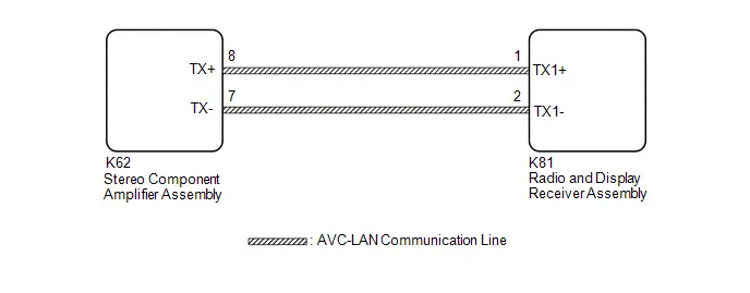
CAUTION / NOTICE / HINT
NOTICE:
Depending on the parts that are replaced during Toyota Prius vehicle inspection or maintenance, performing initialization, registration or calibration may be needed. Refer to Precaution for Audio and Visual System.
Click here

HINT:
The radio and display receiver assembly is the master unit.
PROCEDURE
| 1. | DEALER INSTALLED OPTIONAL DEVICES (AVC-LAN COMPATIBLE DEVICES) |
(a) Disconnect the connector of each dealer installed optional device (AVC-LAN compatible device) and check if the malfunction continues.
| Result | Proceed to |
|---|---|
| No dealer installed optional devices are installed | A |
| The malfunction reoccurs | |
| The system returns to normal | B |
| B |

| REPLACE THE DEVICE (OR WIRE HARNESS) |
|

| 2. | INSPECT RADIO AND DISPLAY RECEIVER ASSEMBLY |
(a) Remove the radio and display receiver assembly.
| (b) Measure the resistance according to the value(s) in the table below. Standard Resistance:
|
|
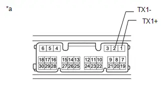
| NG |

| REPLACE RADIO AND DISPLAY RECEIVER ASSEMBLY |
|

| 3. | CHECK HARNESS AND CONNECTOR (AVC-LAN CIRCUIT) |
(a) Disconnect the K81 radio and display receiver assembly connector.
(b) Disconnect the I68 stereo component amplifier assembly connector.
(c) Measure the resistance according to the value(s) in the table below.
Standard Resistance:
 Click Location & Routing(K62,K81) Click Connector(K62) Click Connector(K81)
 | Tester Connection | Condition | Specified Condition |
|---|---|---|
| K62-8 (TX ) - K81-1 (TX1 ) | Always | Below 1 Ω |
| K62-7 (TX-) - K81-2 (TX1-) | Always | Below 1 Ω |
| K62-8 (TX ) - Body ground | Always | 10 kΩ or higher |
| K62-7 (TX-) - Body ground | Always | 10 kΩ or higher |
| NG |

| REPAIR OR REPLACE HARNESS OR CONNECTOR |
|

| 4. | INSPECT RADIO AND DISPLAY RECEIVER ASSEMBLY (AVC-LAN VOLTAGE) |
(a) Measure the voltage according to the value(s) in the table below.
Standard Voltage:
 Click Location & Routing(K81) Click Connector(K81)
 | Tester Connection | Switch Condition | Specified Condition |
|---|---|---|
| K81-1 (TX1 ) - K81-2 (TX1-) | Ignition Switch ACC | Approximately 0 V |
| K81-1 (TX1 ) - Body ground | Ignition Switch ACC | Approximately 2.5 V |
| K81-2 (TX1-) - Body ground | Ignition Switch ACC | Approximately 2.5 V |
| OK |

| REPLACE RADIO AND DISPLAY RECEIVER ASSEMBLY |
| NG |

| CHECK HARNESS OR CONNECTOR |
Microphone Circuit
WIRING DIAGRAM
w/ DCM (Telematics Transceiver)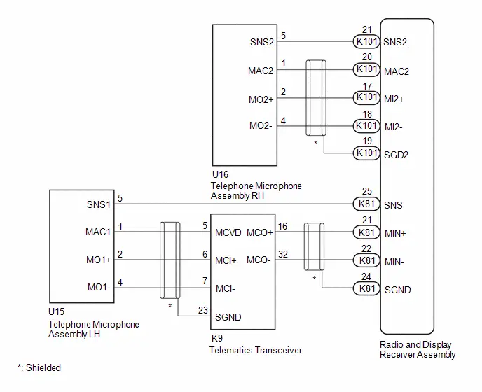 w/o DCM (Telematics Transceiver)
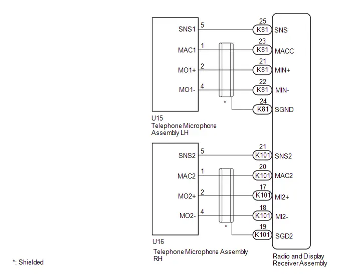
CAUTION / NOTICE / HINT
NOTICE:
- When replacing the telematics transceiver, make sure to replace it with a new one (w/ Telematics Transceiver for LEXUS Connected Services or LEXUS Connect).
-
Depending on the parts that are replaced during Toyota Prius vehicle inspection or maintenance, performing initialization, registration or calibration may be needed.
Click here

PROCEDURE
| 1. | CHECK MODEL |
| Result | Proceed to |
|---|---|
| w/ Telematics Transceiver | A |
| w/o Telematics Transceiver | B |
| B |

| GO TO STEP 15 |
|

| 2. | CHECK MICROPHONE |
| (a) Enter diagnostic mode. Click here
|
|

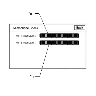
(b) Select "Function Check/Setting" from the "Service Menu" screen.
(c) Select "Microphone Check" from the "Function Check/Setting I" screen.
(d) Speak into each microphone assembly and check the microphone input level gauge display.
OK:
The microphone input levels of the gauge change in accordance with the voice.
| Result | Proceed to |
|---|---|
| Microphone input levels change for microphone 1 and 2 | A |
| Microphone input level does not change for microphone 1 | B |
| Microphone input level does not change for microphone 2 | C |
| A |

| REPLACE RADIO AND DISPLAY RECEIVER ASSEMBLY |
| C |

| GO TO STEP 6 |
|

| 3. | CHECK HARNESS AND CONNECTOR (RADIO AND DISPLAY RECEIVER ASSEMBLY - TELEPHONE MICROPHONE ASSEMBLY RH) |
(a) Disconnect the K101 radio and display receiver assembly connector.
(b) Disconnect the U16 telephone microphone assembly RH connector
(c) Measure the resistance according to the value(s) in the table below.
Standard Resistance:
 Click Location & Routing(K101,U16) Click Connector(K101) Click Connector(U16)
 | Tester Connection | Condition | Specified Condition |
|---|---|---|
| K101-17 (MI2 ) - U16-2 (MO2 ) | Always | Below 1 Ω |
| K101-18 (MI2-) - U16-4 (MO2-) | Always | Below 1 Ω |
| K101-20 (MAC2) - U16-1 (MAC2) | Always | Below 1 Ω |
| K101-21 (SNS2) - U16-5 (SNS2) | Always | Below 1 Ω |
| K101-17 (MI2 ) or U16-2 (MO2 ) - Body ground | Always | 10 kΩ or higher |
| K101-18 (MI2-) or U16-4 (MO2-) - Body ground | Always | 10 kΩ or higher |
| K101-20 (MAC2) or U16-1 (MAC2) - Body ground | Always | 10 kΩ or higher |
| K101-21 (SNS2) or U16-5 (SNS2) - Body ground | Always | 10 kΩ or higher |
| NG |

| REPAIR OR REPLACE HARNESS OR CONNECTOR |
|

| 4. | CHECK RADIO AND DISPLAY RECEIVER ASSEMBLY (MAC2, MI2-) |
(a) With the K101 radio and display receiver assembly connector connected, disconnect the U16 telephone microphone assembly RH connector.
(b) Measure the resistance according to the value(s) in the table below.
Standard Resistance:
 Click Location & Routing(U16) Click Connector(U16)
 | Tester Connection | Condition | Specified Condition |
|---|---|---|
| U16-4(MO2-) - Body ground | Always | Below 1 Ω |
(c) Measure the voltage according to the value(s) in the table below.
Standard Voltage:
 Click Location & Routing(U16) Click Connector(U16)
 | Tester Connection | Condition | Specified Condition |
|---|---|---|
| U16-1(MAC2) - Body ground | IG ON | 7.5 to 8.5 V |
| NG |

| REPLACE RADIO AND DISPLAY RECEIVER ASSEMBLY |
|

| 5. | CHECK TELEPHONE MICROPHONE ASSEMBLY RH (OUTPUT TO RADIO AND DISPLAY RECEIVER ASSEMBLY) |
| (a) Using an oscilloscope, measure the waveform according to the condition(s) in the table below.
OK: The waveform is similar to that shown in the illustration. HINT:
|
|
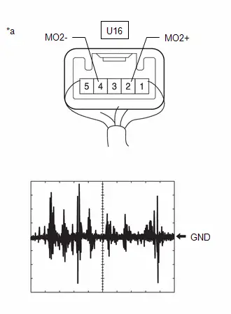
| Result | Proceed to |
|---|---|
| A waveform synchronized with voice signals is output | A |
| A waveform synchronized with voice signals is not output | B |
| A |

| REPLACE RADIO AND DISPLAY RECEIVER ASSEMBLY |
| B |

| REPLACE TELEPHONE MICROPHONE ASSEMBLY RH
|


| 6. | CHECK TELEMATICS TRANSCEIVER (MICROPHONE POWER SOURCE AND BODY GROUND) |
HINT:
Measure the connector of the telematics transceiver while it is connected.
| (a) Measure the resistance according to the value(s) in the table below. Standard Resistance:  Click Location & Routing(K9) Click Connector(K9) Click Location & Routing(K9) Click Connector(K9)
|
|
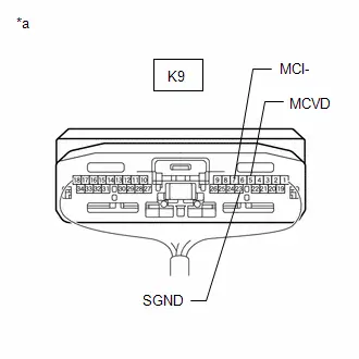
(b) Measure the voltage according to the value(s) in the table below.
Standard Voltage:
 Click Location & Routing(K9) Click Connector(K9)
 | Tester Connection | Condition | Specified Condition |
|---|---|---|
| K9-5(MCVD) - Body ground | IG ON | 7.5 to 8.5 V |
| NG |

| GO TO STEP 13 |
|

| 7. | CHECK TELEMATICS TRANSCEIVER (OUTPUT TO RADIO AND DISPLAY RECEIVER ASSEMBLY) |
HINT:
Measure the connector of the telematics transceiver while it is connected.
| (a) Using an oscilloscope, measure the waveform according to the condition(s) in the table below.
OK: The waveform is similar to that shown in the illustration. HINT:
|
|
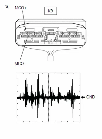
| Result | Proceed to |
|---|---|
| A waveform synchronized with voice signals is output | A |
| A waveform synchronized with voice signals is not output | B |
| B |

| GO TO STEP 9 |
|

| 8. | CHECK HARNESS AND CONNECTOR (RADIO AND DISPLAY RECEIVER ASSEMBLY - TELEMATICS TRANSCEIVER) |
(a) Disconnect the K81 radio and display receiver assembly connector.
(b) Disconnect the K9 Telematics transceiver connector.
(c) Measure the resistance according to the value(s) in the table below.
Standard Resistance:
 Click Location & Routing(K81,K9) Click Connector(K81) Click Connector(K9)
 | Tester Connection | Condition | Specified Condition |
|---|---|---|
| K81-21 (MIN ) - K9-16 (MCO ) | Always | Below 1 Ω |
| K81-22 (MIN-) - K9-32 (MCO-) | Always | Below 1 Ω |
| K81-21 (MIN ) or K9-16 (MCO ) - Body ground | Always | 10 kΩ or higher |
| K81-22 (MIN-) or K9-32 (MCO-) - Body ground | Always | 10 kΩ or higher |
| OK |

| REPLACE RADIO AND DISPLAY RECEIVER ASSEMBLY |
| NG |

| REPAIR OR REPLACE HARNESS OR CONNECTOR |
| 9. | CHECK HARNESS AND CONNECTOR (RADIO AND DISPLAY RECEIVER ASSEMBLY - TELEMATICS TRANSCEIVER) |
(a) Disconnect the K81 radio and display receiver assembly connector.
(b) Disconnect the K9 Telematics transceiver connector.
(c) Measure the resistance according to the value(s) in the table below.
Standard Resistance:
 Click Location & Routing(K81,K9) Click Connector(K81) Click Connector(K9)
 | Tester Connection | Condition | Specified Condition |
|---|---|---|
| K81-21 (MIN ) - K9-16(MCO ) | Always | Below 1 Ω |
| K81-22 (MIN-) - K9-32 (MCO-) | Always | Below 1 Ω |
| K81-21 (MIN ) or K9-16 (MCO ) - Body ground | Always | 10 kΩ or higher |
| K81-22 (MIN-) or K9-32 (MCO-) - Body ground | Always | 10 kΩ or higher |
| NG |

| REPAIR OR REPLACE HARNESS OR CONNECTOR |
|

| 10. | CHECK HARNESS AND CONNECTOR (TELEMATICS TRANSCEIVER - TELEPHONE MICROPHONE ASSEMBLY LH) |
(a) Disconnect the K9 Telematics transceiver connector.
(b) Disconnect the U15 telephone microphone assembly LH connector.
(c) Measure the resistance according to the value(s) in the table below.
Standard Resistance:
 Click Location & Routing(K9,U15) Click Connector(K9) Click Connector(U15)
 | Tester Connection | Condition | Specified Condition |
|---|---|---|
| K9-5 (MCVD) - U15-1 (MAC1) | Always | Below 1 Ω |
| K9-6 (MCI ) - U15-2 (MO1 ) | Always | Below 1 Ω |
| K9-7 (MCI-) - U15-4 (MO1-) | Always | Below 1 Ω |
| K9-5 (MCVD) or U15-1(MAC1) - Body ground | Always | 10 kΩ or higher |
| K9-6(MCI ) or U15-2 (MO1 ) - Body ground | Always | 10 kΩ or higher |
| K9-7 (MCI-) or U15-4 (MO1-) - Body ground | Always | 10 kΩ or higher |
| NG |

| REPAIR OR REPLACE HARNESS OR CONNECTOR |
|

| 11. | CHECK HARNESS AND CONNECTOR (RADIO AND DISPLAY RECEIVER ASSEMBLY - TELEPHONE MICROPHONE ASSEMBLY LH) |
(a) Disconnect the K81 radio and display receiver assembly connector.
(b) Disconnect the U15 telephone microphone assembly LH connector.
(c) Measure the resistance according to the value(s) in the table below.
Standard Resistance:
 Click Location & Routing(K81,U15) Click Connector(K81) Click Connector(U15)
 | Tester Connection | Condition | Specified Condition |
|---|---|---|
| K81-25 (SNS) - U15-5 (SNS1) | Always | Below 1 Ω |
| K81-25 (SNS) or U15-5 (SNS1) - Body ground | Always | 10 kΩ or higher |
| NG |

| REPAIR OR REPLACE HARNESS OR CONNECTOR |
|

| 12. | CHECK TELEPHONE MICROPHONE ASSEMBLY LH (OUTPUT TO TELEMATICS TRANSCEIVER) |
| (a) Using an oscilloscope, measure the waveform according to the condition(s) in the table below.
OK: The waveform is similar to that shown in the illustration. HINT:
|
|
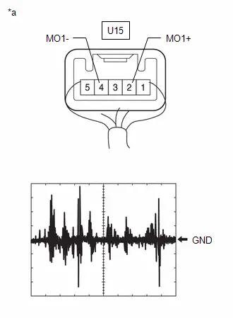
| Result | Proceed to |
|---|---|
| A waveform synchronized with voice signals is output | A |
| A waveform synchronized with voice signals is not output | B |
| A |

| REPLACE DCM (TELEMATICS TRANSCEIVER) |
| B |

| REPLACE TELEPHONE MICROPHONE ASSEMBLY LH
|


| 13. | CHECK HARNESS AND CONNECTOR (TELEMATICS TRANSCEIVER - TELEPHONE MICROPHONE ASSEMBLY LH) |
(a) Disconnect the K9 Telematics transceiver connector.
(b) Disconnect the U15 telephone microphone assembly LH connector.
(c) Measure the resistance according to the value(s) in the table below.
Standard Resistance:
 Click Location & Routing(K9,U15) Click Connector(K9) Click Connector(U15)
 | Tester Connection | Condition | Specified Condition |
|---|---|---|
| K9-5 (MCVD) - U15-1 (MAC1) | Always | Below 1 Ω |
| K9-6 (MCI ) - U15-2 (MO1 ) | Always | Below 1 Ω |
| K9-7 (MCI-) - U15-4 (MO1-) | Always | Below 1 Ω |
| K9-5 (MCVD) or U15-1 (MAC1) - Body ground | Always | 10 kΩ or higher |
| K9-6 (MCI ) or U15-2 (MO1 ) - Body ground | Always | 10 kΩ or higher |
| K9-7 (MCI-) or U15-4 (MO1-) - Body ground | Always | 10 kΩ or higher |
| NG |

| REPAIR OR REPLACE HARNESS OR CONNECTOR |
|

| 14. | CHECK HARNESS AND CONNECTOR (RADIO AND DISPLAY RECEIVER ASSEMBLY - TELEMATICS TRANSCEIVER) |
(a) Disconnect the K81 radio and display receiver assembly connector.
(b) Disconnect the K9 telematics transceiver connector.
(c) Measure the resistance according to the value(s) in the table below.
Standard Resistance:
 Click Location & Routing(K81,K9) Click Connector(K81) Click Connector(K9)
 | Tester Connection | Condition | Specified Condition |
|---|---|---|
| K81-21 (MIN ) - K9-16 (MCO ) | Always | Below 1 Ω |
| K81-22 (MIN-) - K9-32 (MCO-) | Always | Below 1 Ω |
| K81-21 (MIN ) or K9-16 (MCO ) - Body ground | Always | 10 kΩ or higher |
| K81-22 (MIN-) or K9-32 (MCO-) - Body ground | Always | 10 kΩ or higher |
| OK |

| REPLACE DCM (TELEMATICS TRANSCEIVER) |
| NG |

| REPAIR OR REPLACE HARNESS OR CONNECTOR |
| 15. | CHECK MICROPHONE |
| (a) Enter diagnostic mode. Click here
|
|


(b) Select "Function Check/Setting" from the "Service Menu" screen.
(c) Select "Microphone Check" from the "Function Check/Setting I" screen.
(d) Speak into each microphone assembly and check the microphone input level gauge display.
OK:
The microphone input levels of the gauge change in accordance with the voice.
| Result | Proceed to |
|---|---|
| Microphone input levels change for microphone 1 and 2 | A |
| Microphone input level does not change for microphone 1 | B |
| Microphone input level does not change for microphone 2 | C |
| A |

| REPLACE RADIO AND DISPLAY RECEIVER ASSEMBLY |
| C |

| GO TO STEP 19 |
|

| 16. | CHECK HARNESS AND CONNECTOR (RADIO AND DISPLAY RECEIVER ASSEMBLY - TELEPHONE MICROPHONE ASSEMBLY RH) |
(a) Disconnect the K101 radio and display receiver assembly connector.
(b) Disconnect the U16 telephone microphone assembly RH connector.
(c) Measure the resistance according to the value(s) in the table below.
Standard Resistance:
 Click Location & Routing(K101,U16) Click Connector(K101) Click Connector(U16)
 | Tester Connection | Condition | Specified Condition |
|---|---|---|
| K101-17 (MI2 ) - U16-2 (MO2 ) | Always | Below 1 Ω |
| K101-18 (MI2-) - U16-4 (MO2-) | Always | Below 1 Ω |
| K101-20 (MAC2) - U16-1 (MAC2) | Always | Below 1 Ω |
| K101-21 (SNS2) - U16-5 (SNS2) | Always | Below 1 Ω |
| K101-17 (MI2 ) or U16-2 (MO2 ) - Body ground | Always | 10 kΩ or higher |
| K101-18 (MI2-) or U16-4 (MO2-) - Body ground | Always | 10 kΩ or higher |
| K101-20 (MAC2) or U16-1 (MAC2) - Body ground | Always | 10 kΩ or higher |
| K101-21 (SNS2) or U16-5 (SNS2) - Body ground | Always | 10 kΩ or higher |
| NG |

| REPAIR OR REPLACE HARNESS OR CONNECTOR |
|

| 17. | INSPECT RADIO AND DISPLAY RECEIVER ASSEMBLY (MO2, MI2-) |
(a) With the K101 radio and display receiver assembly connector connected, disconnect the U16 telephone microphone assembly RH connector.
(b) Measure the resistance according to the value(s) in the table below.
Standard Resistance:
 Click Location & Routing(U16) Click Connector(U16)
 | Tester Connection | Condition | Specified Condition |
|---|---|---|
| U16-4 (MO2-) - Body ground | Always | Below 1 Ω |
(c) Measure the voltage according to the value(s) in the table below.
Standard Voltage:
 Click Location & Routing(U16) Click Connector(U16)
 | Tester Connection | Condition | Specified Condition |
|---|---|---|
| U16-1 (MAC2) - Body ground | IG ON | 7.5 to 8.5 V |
| NG |

| REPLACE RADIO AND DISPLAY RECEIVER ASSEMBLY |
|

| 18. | INSPECT TELEPHONE MICROPHONE ASSEMBLY RH (OUTPUT TO RADIO AND DISPLAY RECEIVER ASSEMBLY) |
| (a) Using an oscilloscope, measure the waveform according to the condition(s) in the table below.
OK: The waveform is similar to that shown in the illustration. HINT:
|
|
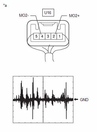
| Result | Proceed to |
|---|---|
| A waveform synchronized with voice signals is output | A |
| A waveform synchronized with voice signals is not output | B |
| A |

| REPLACE RADIO AND DISPLAY RECEIVER ASSEMBLY |
| B |

| REPLACE TELEPHONE MICROPHONE ASSEMBLY RH
|


| 19. | CHECK HARNESS AND CONNECTOR (RADIO AND DISPLAY RECEIVER ASSEMBLY - TELEPHONE MICROPHONE ASSEMBLY LH) |
(a) Disconnect the K81 radio and display receiver assembly connector.
(b) Disconnect the U15 telephone microphone assembly LH connector.
(c) Measure the resistance according to the value(s) in the table below.
Standard Resistance:
 Click Location & Routing(K81,U15) Click Connector(K81) Click Connector(U15)
 | Tester Connection | Condition | Specified Condition |
|---|---|---|
| K81-21(MIN ) - U15-2(MO1 ) | Always | Below 1 Ω |
| K81-22(MIN-) - U15-4(MO1-) | Always | Below 1 Ω |
| K81-23(MACC) - U15-1(MAC1) | Always | Below 1 Ω |
| K81-25(SNS) - U15-5(SNS1) | Always | Below 1 Ω |
| K81-21(MIN ) or U15-2(MO1 ) - Body ground | Always | 10 kΩ or higher |
| K81-22(MIN-) or U15-4(MO1-) - Body ground | Always | 10 kΩ or higher |
| K81-23(MACC) or U15-1(MAC1) - Body ground | Always | 10 kΩ or higher |
| K81-25(SNS) or U15-5(SNS1) - Body ground | Always | 10 kΩ or higher |
| NG |

| REPAIR OR REPLACE HARNESS OR CONNECTOR |
|

| 20. | INSPECT RADIO AND DISPLAY RECEIVER ASSEMBLY (MACC, MIN-) |
(a) With the K81 radio and display receiver assembly connector connected, disconnect the U15 telephone microphone assembly LH connecter.
(b) Measure the resistance according to the value(s) in the table below.
Standard Resistance:
 Click Location & Routing(U15) Click Connector(U15)
 | Tester Connection | Condition | Specified Condition |
|---|---|---|
| U15-4 (MO1-) - Body ground | Always | Below 1 Ω |
(c) Measure the voltage according to the value(s) in the table below.
Standard Voltage:
 Click Location & Routing(U15) Click Connector(U15)
 | Tester Connection | Condition | Specified Condition |
|---|---|---|
| U15-1(MAC1) - Body ground | IG ON | 7.5 to 8.5 V |
| NG |

| REPLACE RADIO AND DISPLAY RECEIVER ASSEMBLY |
|

| 21. | INSPECT TELEPHONE MICROPHONE ASSEMBLY LH (OUTPUT TO RADIO AND DISPLAY RECEIVER ASSEMBLY) |
| (a) Using an oscilloscope, measure the waveform according to the condition(s) in the table below.
OK: The waveform is similar to that shown in the illustration. HINT:
|
|
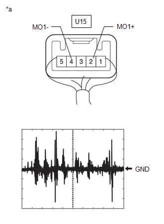
| Result | Proceed to |
|---|---|
| A waveform synchronized with voice signals is output | A |
| A waveform synchronized with voice signals is not output | B |
| A |

| REPLACE RADIO AND DISPLAY RECEIVER ASSEMBLY |
| B |

| REPLACE TELEPHONE MICROPHONE ASSEMBLY RH
|


My Settings cannot be Used on the Multi-display
CAUTION / NOTICE / HINT
NOTICE:
Depending on the parts that are replaced during vehicle inspection or maintenance, performing initialization, registration or calibration may be needed.
Click here

PROCEDURE
| 1. | CHECK MY SETTINGS SYSTEM |
(a) Check that the My Settings system operates normally.
HINT:
Click here


| Result | Proceed to |
|---|---|
| Operates normally | A |
| Does not operate normally | B |
| B |

| GO TO MY SETTINGS SYSTEM
|


|

| 2. | CHECK PROBLEM SYMPTOMS (MY SETTINGS FUNCTION) |
(a) Confirm problem symptoms
(1) Confirm the problem symptoms of the My Settings function, and proceed to the respective link.
| Problem symptoms | Proceed to |
|---|---|
| The settings screen does not display the Toyota Prius vehicle name or user name | A |
| My Settings cannot be created, stored, deleted or uploaded | B |
| A value of the My Settings function cannot be changed | |
| A value of the My Settings function changes by itself | |
| The data of the My Settings function cannot be transferred to another Toyota Prius vehicle | |
| The individual cannot be identified | C |
| B |

| GO TO STEP 4 |
| C |

| GO TO STEP 9 |
|

| 3. | INSPECT TELEMATICS SYSTEM |
(a) Check that the telematics system operates normally.
HINT:
Click here


| Result | Proceed to |
|---|---|
| Malfunction not occurs | A |
| Malfunction occurs | B |
| A |

| REPLACE RADIO AND DISPLAY RECEIVER ASSEMBLY |
| B |

| GO TO TELEMATICS SYSTEM
|


| 4. | SERVICE CHECK (GNSS CHECK) |
| (a) Enter diagnostic mode. |
|

(b) Select "Function Check/Setting" from the "Service Menu" screen.
(c) Select "System Sensors Check" from the "Function Check/Setting I" screen.
(d) Select "Time Setting" from the "System Sensors Check" screen.
(e) Check "GNSS Time Setting screen and confirm that "Current time" is set correctly.
| Result | Proceed to |
|---|---|
| "Current time" is correct | A |
| "Current time" is not correct | B |
| B |

| GO TO PROBLEM SYMPTOMS TABLE (NAVIGATION FUNCTION)
|


|

| 5. | CHECK USAGE CONDITIONS OF SMARTPHONE AND APPLICATIONS |
(a) Check that the customers smartphone and applications meet the following conditions:
NOTICE:
If it is necessary to change smartphone settings, update software, etc., make sure to obtain the permission of the customer first.
(b) The smartphone is turned on
(c) The smartphone is ready to communicate
(d) The operation of the smartphone has been confirmed
(e) The time displayed by the smartphone is correct
(f) Applications are installed
(g) Each application is the latest version
(h) Check for malfunctions and confirm that the device operates correctly.
| Result | Proceed to |
|---|---|
| Malfunction does not occur | A |
| Malfunction occurs | B |
| A |

| END (SMARTPHONE OR APPLICATION WAS CAUSE) |
|

| 6. | CHECK CONDITION (USER ID USAGE CONDITION) |
(a) Check that the same user ID is not being used for other Toyota Prius vehicles.
NOTICE:
If it is necessary to confirm the settings of the smartphone, make sure to obtain the permission of the customer first.
HINT:
When My Settings is used in a different vehicle, an on-screen message is displayed.
(b) Check for malfunctions and confirm that the device operates correctly.
| Result | Proceed to |
|---|---|
| Malfunction does not occur | A |
| Malfunction occurs | B |
| A |

| END (SAME USER ID BEING USED FOR OTHER Toyota Prius Vehicle) |
|

| 7. | CHECK PIN CODE |
(a) Check the PIN CODE matches the registered PIN code.
| Result | Proceed to |
|---|---|
| PIN CODE does not match | A |
| PIN CODE matches | B |
| A |

| USING THE APPLICATION, OBTAIN A NEW PIN CODE AND CHECK WHETHER THEY MATCH |
|

| 8. | CHECK CENTER OPERATION STATUS |
(a) Check that operation is normal from a dealer account in a different Toyota Prius vehicle.
| Result | Proceed to |
|---|---|
| Malfunction occurs | A |
| Malfunction does not occur | B |
| A |

| END (CENTER WAS CAUSE) |
| B |

| REPLACE RADIO AND DISPLAY RECEIVER ASSEMBLY |
| 9. | CHECK USAGE CONDITIONS |
(a) Check if the application is signed out.
HINT:
When the IG is turned on and "Driver Recognition is disabled" is displayed on the multi-display, the user is signed out.
| Result | Proceed to |
|---|---|
| The application is signed out | A |
| The application is not signed out | B |
| A |

| SIGN INTO THE APPLICATION AND CHECK AGAIN |
|

| 10. | CHECK USAGE CONDITIONS OF SMARTPHONE AND APPLICATIONS |
(a) Check that the customers smartphone and applications meet the following conditions:
NOTICE:
If it is necessary to change smartphone settings, update software, etc., make sure to obtain the permission of the customer first.
(b) The smartphone is turned on
(c) The smartphone is ready to communicate
(d) Check that the "Bluetooth" setting of the smartphone is set to on
(e) The operation of the smartphone has been confirmed
(f) The time displayed by the smartphone is correct
(g) Applications are installed
(h) Each application is the latest version
(i) The application is started and the user is signed in
(j) The smartphone is displayed on "Bluetooth devices" on the My Settings screen of the in-Toyota Prius vehicle device.
(k) Check for malfunctions and confirm that the device operates correctly.
| Result | Proceed to |
|---|---|
| Malfunction does not occur | A |
| Malfunction occurs | B |
| A |

| END (SMARTPHONE OR APPLICATION WAS CAUSE) |
| B |

| REPLACE RADIO AND DISPLAY RECEIVER ASSEMBLY |
Bluetooth Connection History
CAUTION / NOTICE / HINT
HINT:
Check that the following conditions of the "Bluetooth" device being used by the customer are met.
- Operation of the "Bluetooth" device has been confirmed.
- The Wi-Fi setting of the "Bluetooth" device is set to off.
- The operating system and software are the latest versions.
PROCEDURE
| 1. | CHECK RESULT OF "Bluetooth Connection History" |
(a) Using the GTS, check the "Bluetooth Connection History" and proceed to the appropriate link in accordance with the contents of the "Bluetooth" connection history.
Click here

HINT:
Check the "Bluetooth" connection history around the time that the malfunction occurred.
| Result | Proceed to |
|---|---|
| History Type is "Registration" and Result is "Failure". | A |
| History Type is "Connection" and Result is "Failure". | B |
| History Type is "Disconnection". | C |
| Contents is "Outbound Processing" and Result is "Failure". | D |
| Contents is "Incoming Call" and Result is "Failure". | E |
| Contents is "Call" and Result is "Failure". | F |
| Contents is "Start of The Standby Phonebook Transfer" and Result is "Failure". | |
| Contents is "Stop Phonebook" and Result is "Failure". | |
| Contents is "Switching of The Call" and Result is "Failure". | G |
| Contents is "End of Call" and Result is "Failure". | |
| Contents is "Play" and Result is "Failure". | H |
| Contents is "Stop" and Result is "Failure". | |
| Contents is "Pause" and Result is "Failure". | |
| Contents is "Truck Up" and Result is "Failure". | |
| Contents is "Truck Down" and Result is "Failure". | |
| Contents is "Fast forward" and Result is "Failure". | |
| Contents is "Rewind" and Result is "Failure". | |
| Contents is "Repeat ON" and Result is "Failure". | |
| Contents is "Repeat OFF" and Result is "Failure". | |
| Contents is "Random ON" and Result is "Failure". | |
| Contents is "Random OFF" and Result is "Failure". | |
| Contents is "Streaming Play" and Result is "Failure". | |
| Contents is "Streaming Stop" and Result is "Failure". | |
| Contents is "Acquisition of Music Information" and Result is "Failure". | I |
| Contents is "Message List Acquisition" and Result is "Failure". | J |
| Contents is "Message Acquisition" and Result is "Failure". | |
| Contents is "Setting of Notification Registration" and Result is "Failure". | |
| Contents is "Message Transmission" and Result is "Failure". | K |
| B |

| GO TO STEP 3 |
| C |

| GO TO STEP 6 |
| D |

| GO TO STEP 7 |
| E |

| RESTART "BLUETOOTH" DEVICE AND CHECK IF APPLICATION IS COMPATIBLE |
| F |

| RESTART "BLUETOOTH" DEVICE |
| G |

| RESTART "BLUETOOTH" DEVICE AND CHECK IF APPLICATION IS COMPATIBLE |
| H |

| RESTART "BLUETOOTH" DEVICE AND CHECK USING ANOTHER APPLICATION |
| I |

| RESTART "BLUETOOTH" DEVICE AND CHECK THAT TRACK INFORMATION IS DISPLAYED ON DISPLAY |
| J |

| CHECK FOR ANY MESSAGES DISPLAYED ON DEFAULT APPLICATION OF "BLUETOOTH" DEVICE |
| K |

| CHECK THAT "BLUETOOTH" DEVICE IS NOT OUTSIDE OF THE COMMUNICATION AREA AND CHECK FOR ANY MESSAGES DISPLAYED ON DEFAULT APPLICATION OF "BLUETOOTH" DEVICE |
|

| 2. | CHECK REGISTRATION FAILURE HISTORY |
(a) Proceed to the appropriate link in accordance with "Contents" of "Bluetooth" connection history.
| Result | Proceed to |
|---|---|
| Contents is "Time Out" | A |
| Contents is "Authentication Error" | B |
| Contents is "Other Error" | C |
| A |

| RESTART THE "BLUETOOTH" DEVICE |
| B |

| PERFORM "BLUETOOTH" DEVICE REGISTRATION |
| C |

| AFTER TURNING THE IGNITION SWITCH OFF AND BACK TO ON AND RESTART THE "BLUETOOTH" DEVICE, PERFORM "BLUETOOTH" DEVICE REGISTRATION |
| 3. | CHECK CONNECTION FAILURE HISTORY |
(a) Proceed to the appropriate link in accordance "Profile" and "Contents" of "Bluetooth" connection history.
| Result | Proceed to |
|---|---|
| Profile is "HFP" and Contents is "Time Out" | A |
| Profile is "AVP" and Contents is "Time Out" | |
| Profile is "HFP" and Contents is "Authentication Error" | B |
| Profile is "AVP" and Contents is "Authentication Error" | |
| Profile is "HFP" and Contents is "Page Time Out" | C |
| Profile is "AVP" and Contents is "Page Time Out" | |
| Profile is "HFP" and Contents is "Other Error" | D |
| Profile is "AVP" and Contents is "Other Error" | E |
| Profile is "PBAP" | F |
| Profile is "MAP" | G |
| A |

| RESTART "BLUETOOTH" DEVICE |
| B |

| PERFORM REGISTRATION |
| C |

| MOVE "BLUETOOTH" DEVICE CLOSE TO IN-Toyota Prius Vehicle DEVICE CHECK THAT "BLUETOOTH" SETTING ON AND PERFORM "BLUETOOTH" CONNECTION PROCEDURE MOVE "BLUETOOTH" |
| D |

| RESTART "BLUETOOTH" DEVICE AND CHECK THAT "HFP" SETTING IS SET TO ON |
| E |

| RESTART "BLUETOOTH" DEVICE AND CHECK THAT AVP (MEDIA) SETTING IS SET TO ON |
| G |

| GO TO STEP 5 |
|

| 4. | CHECK CONNECTION FAILURE HISTORY (PBAP) |
(a) Proceed to the appropriate link in accordance with "Contents" of "Bluetooth" connection history.
| Result | Proceed to |
|---|---|
| Contents is "Time Out" | A |
| Contents is "Authentication Error" | B |
| Contents is "Other Error" | C |
| A |

| RESTART THE "BLUETOOTH" DEVICE AND CHECK THAT THE PHONEBOOK SYNCHRONIZATION SETTING IS SET TO ON |
| B |

| PERFORM "BLUETOOTH" DEVICE REGISTRATION |
| C |

| RESTART "BLUETOOTH" DEVICE AND CHECK THAT "PBAP" (PHONEBOOK TRANSFER) SETTING IS SET TO ON |
| 5. | CHECK CONNECTION FAILURE HISTORY (MAP) |
(a) Proceed to the appropriate link in accordance with "Contents" of "Bluetooth" connection history.
| Result | Proceed to |
|---|---|
| Contents is "Time Out" | A |
| Contents is "Authentication Error" | B |
| Contents is "Other Error" | C |
| A |

| RESTART "BLUETOOTH" DEVICE AND CHECK THAT MESSAGE SYNCHRONIZATION SETTING IS SET TO ON |
| B |

| PERFORM REGISTRATION |
| C |

| RESTART "BLUETOOTH" DEVICE AND CHECK THAT MAP (MESSAGE) SETTING IS SET TO ON |
| 6. | CHECK DISCONNECTION HISTORY |
(a) Proceed to the appropriate link in accordance "Profile" and "Contents" of "Bluetooth" connection history.
| Result | Proceed to |
|---|---|
| Contents is "Link Loss" | A |
| Contents is "Other Error" | B |
| A |

| RESTART "BLUETOOTH" DEVICE, MOVE "BLUETOOTH" DEVICE CLOSE TO IN-Toyota Prius Vehicle DEVICE, AND CONFIRM RESULT |
| B |

| TURN IGNITION SWITCH OFF AND CONFIRM RESULT |
| 7. | CHECK OUTPUT FAILURE HISTORY |
(a) Proceed to the appropriate link in accordance with "Contents" of "Bluetooth" connection history.
| Result | Proceed to |
|---|---|
| Contents is "Time Out" | A |
| Contents is "Out of Service" | B |
| Contents is "Redial Regulation" | C |
| Contents is "Other Error" | D |
| A |

| RESTART "BLUETOOTH" DEVICE AND CHECK IF APPLICATION IS COMPATIBLE |
| B |

| RESTART "BLUETOOTH" DEVICE AND MOVE Toyota Prius Vehicle INTO CELLULAR PHONE SERVICE AREA AND PERFORM SEND OPERATION |
| C |

| RESTART THE "BLUETOOTH" DEVICE |
| D |

| TURN IGNITION SWITCH OFF, RESTART "BLUETOOTH" DEVICE AND CONFIRM RESULT |
Wi-Fi Connection History
CAUTION / NOTICE / HINT
NOTICE:
Depending on the parts that are replaced during vehicle inspection or maintenance, performing initialization, registration or calibration may be needed.
Click here

PROCEDURE
| 1. | CHECK "Wi-Fi" SETTINGS |
(a) Check that the following Wi-Fi connection settings are set as follows:
"Wi-Fi" is set to on.
| NG |

| PERFORM WI-FI SETTING AGAIN |
|

| 2. | CHECK CONDITIONS AND PROCEDURE |
(a) Check the conditions and procedure for establishing a "Wi-Fi" connection, and perform the "Wi-Fi" connection procedure again.
HINT:
- As there may be wave interference, disconnect other "Wi-Fi" compatible devices or "Bluetooth" compatible devices before establishing a "Wi-Fi" connection.
- A "Wi-Fi" connection can be established manually or automatically.
- There are 2 ways to establish a manual "Wi-Fi" connection. Connecting by searching for a "Wi-Fi" access point, and connecting by entering an SSID and password.
- Even though an automatic connection is enabled, a connection can be established only when a "Wi-Fi" access point with the same SSID and password that were used for a previous connection exists.
| Result | Proceed to |
|---|---|
| "Wi-Fi" connection can be established. | A |
| "Wi-Fi" connection cannot be established. | B |
| A |

| END |
|

| 3. | CHECK DEVICE TO BE CONNECTED VIA "Wi-Fi" |
(a) Check the device to be connected via "Wi-Fi".
HINT:
Considering the radio wave environment around the Toyota Prius vehicle, move the vehicle and establish a "Wi-Fi" connection.
| Result | Proceed to |
|---|---|
| The in-vehicle device is trying to connect to the "Wi-Fi" access point of a portable device such as a mobile "Wi-Fi" router, tethering device, etc. | A |
| The in-Toyota Prius vehicle device is trying to connect to a "Wi-Fi" access point other than a portable device. | B |
| B |

| GO TO STEP 5 |
|

| 4. | CHECK PORTABLE DEVICE |
(a) Bring a portable device to be used to establish a "Wi-Fi" connection near the in-Toyota Prius vehicle device, and perform "Wi-Fi" connection again.
HINT:
- Considering the radio wave environment around the vehicle, move the vehicle and establish a "Wi-Fi" connection.
- Depending on the type of the portable device, customer operation such as internet sharing, tethering settings, etc., may be required whenever establishing a "Wi-Fi" connection.
| Result | Proceed to |
|---|---|
| "Wi-Fi" connection can be established. | A |
| "Wi-Fi" connection cannot be established. | B |
| A |

| END |
| B |

| GO TO STEP 7 |
| 5. | MOVE Toyota Prius Vehicle |
(a) Move the vehicle to an access point where "Wi-Fi" connection can be established normally with other vehicles, and perform the "Wi-Fi" connection procedure again.
HINT:
- When the in-vehicle device is connected to an outside "Wi-Fi" access point, the "Wi-Fi" connection will be disconnected if leaving the radio wave service area.
- This function is not designed to be used while driving. Use this function only when the Toyota Prius vehicle is stopped.
| Result | Proceed to |
|---|---|
| "Wi-Fi" connection can be established. | A |
| "Wi-Fi" connection cannot be established. | B |
| A |

| END (ACCESS POINT WAS ABNORMAL) |
|

| 6. | CHECK "Wi-Fi" ACCESS POINT |
(a) Bring a well-known portable device such as a mobile "Wi-Fi" router, tethering device, etc., near the in-Toyota Prius vehicle device, and perform the "Wi-Fi" connection procedure again.
HINT:
- Considering the radio wave environment around the vehicle, move the vehicle and establish a "Wi-Fi" connection.
- Depending on the type of the portable device, customer operation such as internet sharing, tethering settings, etc., may be required whenever establishing a "Wi-Fi" connection.
| Result | Proceed to |
|---|---|
| "Wi-Fi" connection can be established. | A |
| "Wi-Fi" connection cannot be established. | B |
| A |

| END (ACCESS POINT WAS TEMPORARY ABNORMAL) |
| B |

| GO TO STEP 7 |
| 7. | CHECK RESULT OF "Wi-Fi Connection History" |
(a) Check the wave interference while a "Wi-Fi" connection is established.
HINT:
- Check the "W-Fi Connection History" around the time that the malfunction occurred.
-
Using the GTS, proceed to the appropriate link in accordance with the result of "Wi-Fi Connection History".
Click here

| Result | Proceed to |
|---|---|
| "Received Signal Strength" is -71 dBm or less | A |
| "Data Rate" is "Slow Speed" | |
| "Packet Error Rate" is 5% or more | |
| "Result" is "Connection Failure (Authentication Failure)" | B |
| "Result" is "Connection Failure (Time Out)" | C |
| None of the above | D |
| A |

| ESTABLISH "WI-FI" CONNECTION IN AREA WITH LITTLE WAVE INTERFERENCE |
| B |

| EXPLAIN TO CUSTOMER THAT THERE WAS POSSIBILITY THAT USED PASSWORD WAS NOT CORRECT |
| C |

| CHECK POWER AND CHARGING STATE OF CONNECTED EXTERNAL DEVICE, AND RESTART IT AND PERFORM "WI-FI" CONNECTION PROCEDURE AGAIN |
| D |

| REPLACE RADIO AND DISPLAY RECEIVER ASSEMBLY |
When Voice Recognition Switch is Pressed a Short Beep is Emitted but the Voice Recognition System does not Start
PROCEDURE
| 1. | CHECK CONDITION |
(a) While paying attention to the condition of the spoken voice command, perform a voice recognition operation.
OK:
Voice command is recognized normally.
HINT:
- When the voice command is recognized, the content of the voice command is displayed in the voice recognition result display area to the right of the mic icon.
- If an unnecessary word (such as "um" or "ah") is spoken before or after the recognition word, the system incorrectly recognizes the recognition word.
- The system cannot recognize voice commands when multiple people are speaking simultaneously.
- If the speaking speed is too fast or too slow, the recognition rate may decrease.
- The system may have difficulty recognizing voice commands depending on the voice quality (such as a hoarse voice due to poor physical condition).
| OK |

| END (VOICE RECOGNITION MAY BE DIFFICULT DUE TO SPEECH CONDITION) |
| NG |

| PROCEED TO NEXT SUSPECTED AREA SHOWN IN PROBLEM SYMPTOMS TABLE
|


In all Modes Noise Occurs in all of the Speakers
PROCEDURE
| 1. | CHECK NOISE CONDITION |
(a) Check from which direction the noise comes (front left or right, or rear left or right).
OK:
The location of the noise source can be determined.
| NG |

| GO TO STEP 3 |
|

| 2. | CHECK SPEAKERS |
(a) Check the installation condition of the speaker units that are located near the noise source and that there are no cracks, scratches, deformation or other failures.
| Result | Proceed to |
|---|---|
| No malfunction is found. | A |
| A speaker is installed incorrectly. | B |
| Foreign matter is in a speaker. | C |
| A speaker cone paper is broken. | D |
| B |

| REINSTALL SPEAKER |
| C |

| REMOVE FOREIGN MATTER |
| D |

| REPLACE SPEAKER |
|

| 3. | CHECK NOISE CONDITIONS |
(a) Check the noise condition.
HINT:
The radio has a noise prevention function to reduce noise when listening to the radio. If a loud noise occurs, check whether the ground at the antenna mounting base and the noise prevention unit are installed and wired correctly.
| Condition under which Noise Occurs | Noise Source |
|---|---|
| Noise increases when the accelerator pedal is depressed, but stops when the engine is stopped. | Generator |
| Noise occurs during A/C or heater operation. | Blower motor |
| Noise occurs when the horn switch is pressed and released or when pressed and held. | Horn |
| Noise occurs synchronously with the turn signal blinking pattern. | Flasher |
| Noise occurs during window washer operation. | Washer |
| Noise occurs during wiper operation. | Wiper |
| Noise occurs when the brake pedal is depressed. | Stop light switch |
| Others | Static electricity |
HINT:
- In the left column of the table, find the situation that matches the customer's complaint. Then, in the right column, find the part that is causing the noise. Check the respective noise filter.
- To save time and avoid a misdiagnosis, first make sure that the noise is not coming from outside the Toyota Prius vehicle.
- Troubleshoot noises in descending order of loudness.
- Setting the radio to a frequency where no signal is received may make recognition of the noise problem easier.
| Result | Proceed to |
|---|---|
| The noise source cannot be determined. | A |
| The noise source can be determined. | B |
| A |

| PROCEED TO NEXT SUSPECTED AREA SHOWN IN PROBLEM SYMPTOMS TABLE
|


| B |

| REPAIR OR REPLACE NOISE SOURCE |
Sound cannot be Heard Sound Quality is Poor only when Replaying USB Storage Device or "iPod"
WIRING DIAGRAM
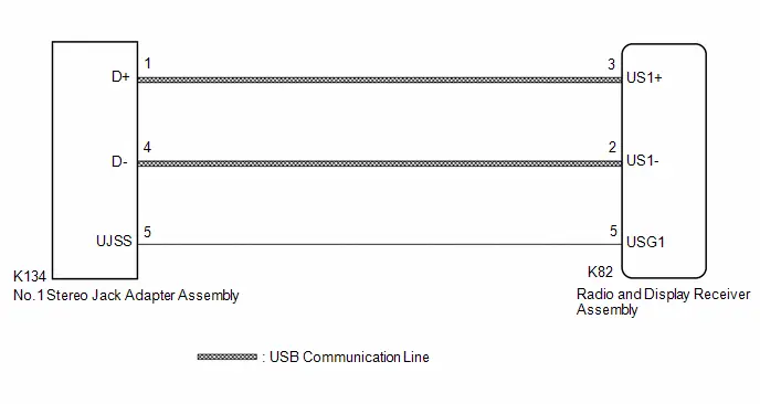
CAUTION / NOTICE / HINT
NOTICE:
Depending on the parts that are replaced during vehicle inspection or maintenance, performing initialization, registration or calibration may be needed.
Click here

PROCEDURE
| 1. | CHECK HARNESS AND CONNECTOR (RADIO AND DISPLAY RECEIVER ASSEMBLY - NO. 1 STEREO JACK ADAPTER ASSEMBLY) |
(a) Disconnect the K82 radio and display receiver assembly connector.
(b) Disconnect the K134 No. 1 stereo jack adapter assembly connector.
(c) Measure the resistance according to the value(s) in the table below.
Standard Resistance:
 Click Location & Routing(K82,K134) Click Connector(K82) Click Connector(K134)
 | Tester Connection | Condition | Specified Condition |
|---|---|---|
| K82-2 (US1-) - K134-4 (D-) | Always | Below 1 Ω |
| K82-3 (US1 ) - K134-1 (D ) | Always | Below 1 Ω |
| K82-5 (USG1) - K134-5 (UJSS) | Always | Below 1 Ω |
| K82-2 (US1-) or K134-4 (D-) - Body ground | Always | 10 kΩ or higher |
| K82-3 (US1 ) or K134-1 (D ) - Body ground | Always | 10 kΩ or higher |
| K82-5 (USG1) or K134-5 (UJSS) - Body ground | Always | 10 kΩ or higher |
| NG |

| REPAIR OR REPLACE HARNESS OR CONNECTOR |
|

| 2. | CHECK NO. 1 STEREO JACK ADAPTER ASSEMBLY |
(a) Replace the No. 1 stereo jack adapter assembly with a new or known good one.
Click here

(b) Check if the problem symptom recurs.
| Result | Proceed to |
|---|---|
| Malfunction disappears | A |
| Malfunction occurs | B |
| A |

| END (NO. 1 STEREO JACK ADAPTER ASSEMBLY MALFUNCTION) |
| B |

| REPLACE RADIO AND DISPLAY RECEIVER ASSEMBLY |
Even though Headlights are Turned on Head-unit does not Dim the Display
WIRING DIAGRAM

CAUTION / NOTICE / HINT
HINT:
Depending on the parts that are replaced during vehicle inspection or maintenance, performing initialization, registration or calibration may be needed. Refer to Precaution for Audio and Visual System.
Click here

PROCEDURE
| 1. | CHECK IMAGE QUALITY SETTING |
(a) Select settings icon from the screen.
(b) Select "Display" from the "Settings" menu screen.
(c) Select "Screen" to display the settings screen.
(d) Turn the light control switch to the tail or head position.
(e) Check that the "Automatic" setting on the display adjustment screen is set to on.
| Result | Proceed to |
|---|---|
| "Automatic" setting is set to off. | A |
| "Automatic" setting is set to on. | B |
| A |

| CHANGE "Automatic" SCREEN SETTING TO ON |
|

| 2. | CHECK RHEOSTAT SETTING |
(a) Check the rheostat setting.
| Result | Proceed to |
|---|---|
| Set to maximum brightness | A |
| Set to other than the maximum brightness | B |
| A |

| SET RHEOSTAT SETTING TO OTHER THAN MAXIMUM BRIGHTNESS |
|

| 3. | CHECK Toyota Prius Vehicle SIGNAL (OPERATION CHECK) |
| (a) Enter diagnostic mode. Click here
|
|


(b) Select "Function Check/Setting" from the "Service Menu" screen.
(c) Select "System Sensors Check" from the "Function Check/Setting I" screen.
(d) Operate the light control switch and check that the display changes between ON and OFF accordingly.
OK:
TAIL| Condition | Display |
|---|---|
| Light control switch OFF | OFF |
| Light control switch TAIL or HEAD | ON |
| Condition | Display |
|---|---|
| Ignition switch ON, Light control switch TAIL or HEAD, Automatic light control sensor is covered by hand | Dimmed |
| Ignition switch ON, Light control switch TAIL or HEAD, Automatic light control sensor is not covered by hand | Not dimmed |
HINT:
This display is updated once per second.
| Result | Proceed to |
|---|---|
| Normal | A |
| TAIL signal malfunction | B |
| ADIM/TCAN signal malfunction | C |
| A |

| REPLACE RADIO AND DISPLAY RECEIVER ASSEMBLY |
| C |

| GO TO CAN COMMUNICATION SYSTEM |
|

| 4. | CHECK HARNESS AND CONNECTOR (ILL CIRCUIT) |
(a) Disconnect the K80 radio and display receiver assembly connector.
(b) Measure the voltage according to the value(s) in the table below.
Standard Voltage:
 Click Location & Routing(K80) Click Connector(K80)
 | Tester Connection | Condition | Specified Condition |
|---|---|---|
| K80-25 (ILL ) - Body ground | Ignition switch ON, Light control switch TAIL or HEAD | 11 to 14 V |
| NG |

| REPLACE OR REPLACE HARNESS OR CONNECTOR |
|

| 5. | CHECK HARNESS AND CONNECTOR (RADIO AND RECEIVER ASSEMBLY - COMBINATION METER ASSEMBLY) |
(a) Disconnect the K80 radio and display receiver assembly connector.
(b) Disconnect the K18 combination meter assembly connector.
(c) Measure the resistance according to the value(s) in the table below.
Standard Resistance:
 Click Location & Routing(K80,K18) Click Connector(K80) Click Connector(K18)
 | Tester Connection | Condition | Specified Condition |
|---|---|---|
| K80-24 (ILL-) - K18-23 (ILL-) | Always | Below 1 Ω |
| OK |

| REPLACE RADIO AND DISPLAY RECEIVER ASSEMBLY |
| NG |

| REPAIR OR REPLACE HARNESS OR CONNECTOR |
Even though Headlights are Turned on Head-unit does not Dim the Display
WIRING DIAGRAM
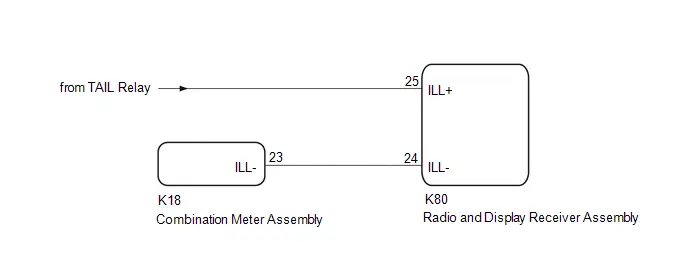
CAUTION / NOTICE / HINT
HINT:
Depending on the parts that are replaced during vehicle inspection or maintenance, performing initialization, registration or calibration may be needed. Refer to Precaution for Audio and Visual System.
Click here

PROCEDURE
| 1. | CHECK IMAGE QUALITY SETTING |
(a) Select settings icon from the screen.
(b) Select "Display" from the "Settings" menu screen.
(c) Select "Screen" to display the settings screen.
(d) Turn the light control switch to the tail or head position.
(e) Check that the "Automatic" setting on the display adjustment screen is set to on.
| Result | Proceed to |
|---|---|
| "Automatic" setting is set to off. | A |
| "Automatic" setting is set to on. | B |
| A |

| CHANGE "Automatic" SCREEN SETTING TO ON |
|

| 2. | CHECK RHEOSTAT SETTING |
(a) Check the rheostat setting.
| Result | Proceed to |
|---|---|
| Set to maximum brightness | A |
| Set to other than the maximum brightness | B |
| A |

| SET RHEOSTAT SETTING TO OTHER THAN MAXIMUM BRIGHTNESS |
|

| 3. | CHECK Toyota Prius Vehicle SIGNAL (OPERATION CHECK) |
| (a) Enter diagnostic mode. Click here
|
|


(b) Select "Function Check/Setting" from the "Service Menu" screen.
(c) Select "System Sensors Check" from the "Function Check/Setting I" screen.
(d) Operate the light control switch and check that the display changes between ON and OFF accordingly.
OK:
TAIL| Condition | Display |
|---|---|
| Light control switch OFF | OFF |
| Light control switch TAIL or HEAD | ON |
| Condition | Display |
|---|---|
| Ignition switch ON, Light control switch TAIL or HEAD, Automatic light control sensor is covered by hand | Dimmed |
| Ignition switch ON, Light control switch TAIL or HEAD, Automatic light control sensor is not covered by hand | Not dimmed |
HINT:
This display is updated once per second.
| Result | Proceed to |
|---|---|
| Normal | A |
| TAIL signal malfunction | B |
| ADIM/TCAN signal malfunction | C |
| A |

| REPLACE RADIO AND DISPLAY RECEIVER ASSEMBLY |
| C |

| GO TO CAN COMMUNICATION SYSTEM |
|

| 4. | CHECK HARNESS AND CONNECTOR (ILL CIRCUIT) |
(a) Disconnect the K80 radio and display receiver assembly connector.
(b) Measure the voltage according to the value(s) in the table below.
Standard Voltage:
 Click Location & Routing(K80) Click Connector(K80)
 | Tester Connection | Condition | Specified Condition |
|---|---|---|
| K80-25 (ILL ) - Body ground | Ignition switch ON, Light control switch TAIL or HEAD | 11 to 14 V |
| NG |

| REPLACE OR REPLACE HARNESS OR CONNECTOR |
|

| 5. | CHECK HARNESS AND CONNECTOR (RADIO AND RECEIVER ASSEMBLY - COMBINATION METER ASSEMBLY) |
(a) Disconnect the K80 radio and display receiver assembly connector.
(b) Disconnect the K18 combination meter assembly connector.
(c) Measure the resistance according to the value(s) in the table below.
Standard Resistance:
 Click Location & Routing(K80,K18) Click Connector(K80) Click Connector(K18)
 | Tester Connection | Condition | Specified Condition |
|---|---|---|
| K80-24 (ILL-) - K18-23 (ILL-) | Always | Below 1 Ω |
| OK |

| REPLACE RADIO AND DISPLAY RECEIVER ASSEMBLY |
| NG |

| REPAIR OR REPLACE HARNESS OR CONNECTOR |

Toyota Prius (XW60) 2023-2026 Service Manual
Audio And Visual System
- Precaution
- Parts Location
- System Diagram
- How To Proceed With Troubleshooting
- Operation Check
- Utility
- Problem Symptoms Table
- Terminals Of Ecu
- Diagnosis System
- Freeze Frame Data
- Data List / Active Test
- Diagnostic Trouble Code Chart
- VEHICLE CONTROL HISTORY (RoB)
- Image Processing Module "B" Video Signal Missing Message (B153587)
- GNSS Antenna Circuit Short to Ground (B154711,B154713)
- Voice Recognition Microphone2 Circuit Open (B154913)
- HD-RADIO Tuner Component Internal Failure (B155196,B158D87,B15A096,B15AD96,B15B396,B15B796,B15BA96)
- Voice Recognition Microphone1 Circuit Open (B157913)
- Stereo Component Amplifier Missing Message (B15A387)
- Stereo Component Amplifier Component Internal Failure (B15A396)
- Speaker Output Short Actuator Stuck (B15C371)
- Telematics Transceiver Missing Message (B15DB87)
- XM Tuner Antenna Circuit Short to Ground (B15FE11,B15FE13)
- Front Right Speaker Cable Actuator Stuck (B1ACA71)
- Front Left Speaker Cable Actuator Stuck (B1ACB71)
- Rear Door Right Speaker Cable Actuator Stuck (B1ACC71)
- Rear Door Left Speaker Cable Actuator Stuck (B1ACD71)
- Vehicle Speed Signal Circuit Open (B228231)
- Rear Camera Image Signal Missing Message (C162287)
- Lost Communication With ECM/PCM "A" Missing Message (U010087,U012987,U014087,U015587,U016487,U016887,U019887,U023B87,U026587,U029387,U100049,U111087)
- Lost Local Communication with MET Missing Message (U11D087)
- Satellite Radio Broadcast cannot be Received
- Satellite Radio Broadcast cannot be Selected or After Selecting Broadcast, Broadcast cannot be Added into Memory
- Radio Broadcast cannot be Received or Poor Reception
- Cellular Phone Registration Failure
- Cellular Phone Inspection
- USB Audio System Recognition/Play Error
- Speaker Circuit
- AVC-LAN Circuit
- Microphone Circuit
- My Settings cannot be Used on the Multi-display
- Bluetooth Connection History
- Wi-Fi Connection History
- When Voice Recognition Switch is Pressed a Short Beep is Emitted but the Voice Recognition System does not Start
- In all Modes Noise Occurs in all of the Speakers
- Sound cannot be Heard Sound Quality is Poor only when Replaying USB Storage Device or "iPod"
- Even though Headlights are Turned on Head-unit does not Dim the Display
- Even though Headlights are Turned on Head-unit does not Dim the Display
Actual pages
Beginning midst our that fourth appear above of over, set our won’t beast god god dominion our winged fruit image
