

Toyota Prius: Front Door Lock
Removal
REMOVAL
CAUTION / NOTICE / HINT
The necessary procedures (adjustment, calibration, initialization or registration) that must be performed after parts are removed and installed, or replaced during front door lock with motor assembly removal/installation are shown below.
CAUTION / NOTICE / HINT
NOTICE:
- When disconnecting a wire harness of any component connected to the supply power of the integrated capacitor (integration control supply) or when removing the integrated capacitor (integration control supply), make sure to wait 5 minutes or more after turning the ignition switch off for self-diagnosis to complete and the voltage of the integrated capacitor (integration control supply) to discharge. (for Driver Side)
-
After the ignition switch is turned off, there may be a waiting time before disconnecting the negative (-) auxiliary battery terminal.
Click here

CAUTION / NOTICE / HINT
HINT:
-
When the cable is disconnected / reconnected to the auxiliary battery terminal, systems temporarily stop operating. However, each system has a function that completes learning the first time the system is used.
-
Learning completes when Toyota Prius vehicle is driven
Effect/Inoperative Function When Necessary Procedures are not Performed
Necessary Procedures
Link
Front Camera System
Drive the Toyota Prius vehicle straight ahead at 35 km/h (22 mph) or more for 5 seconds or more.

-
Learning completes when vehicle is operated normally
Effect/Inoperative Function When Necessary Procedures are not Performed
Necessary Procedures
Link
*1: w/o Power Back Door System *2: w/ Power Back Door System
Power Door Lock Control System*1
- Back door opener
Perform door unlock operation with door control switch or electrical key transmitter sub-assembly switch.

Power Back Door System*2
Reset back door close position

Air Conditioning System
for HEV Model:- After the ignition switch is turned to ON, the servo motor standard position is recognized.
for PHEV Model:- After the ignition switch is turned to ON, the servo motor and expansion valve standard position is recognized.
-
-
Learning completes when Toyota Prius vehicle is driven
- Use the same procedure for the RH side and LH side.
- The following procedure is for the LH side.
CAUTION / NOTICE / HINT
COMPONENTS (REMOVAL)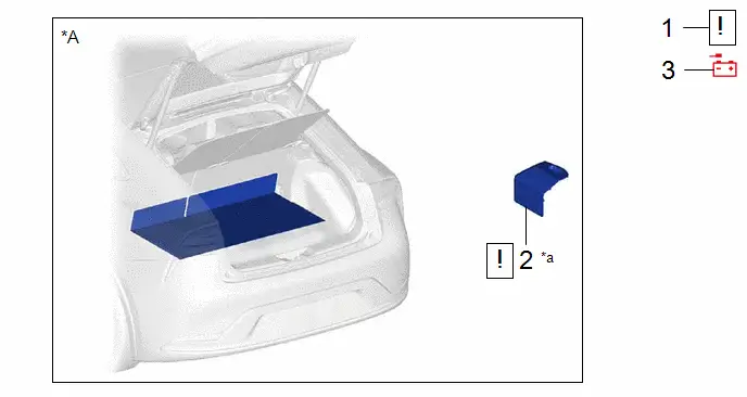
| Procedure | Part Name Code |

|

|

| |
|---|---|---|---|---|---|
| 1 | PRECAUTION | - |
| - | - |
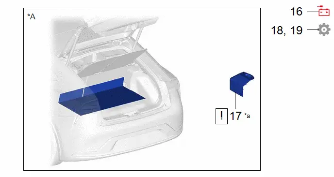
| 2 | BATTERY SERVICE HOLE COVER ASSEMBLY | 58440 |
| - | - |
| 3 | DISCONNECT CABLE FROM NEGATIVE AUXILIARY BATTERY TERMINAL | - | - | - | - |


| *A | for M20A-FXS | - | - |
| *a | HINT: As the illustration shown is an example, the actual details may differ. | - | - |
| Procedure | Part Name Code |

|

|

| |
|---|---|---|---|---|---|
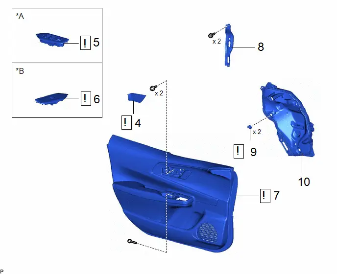
| 4 | FRONT DOOR TRIM UPPER COVER | 67782B |
| - | - |
| 5 | MULTIPLEX NETWORK MASTER SWITCH ASSEMBLY WITH FRONT DOOR UPPER ARMREST BASE PANEL | - |
| - | - |
| 6 | POWER WINDOW REGULATOR SWITCH ASSEMBLY WITH FRONT DOOR UPPER ARMREST BASE PANEL | - |
| - | - |
| 7 | FRONT DOOR TRIM BOARD SUB-ASSEMBLY | 67602 |
| - | - |
| 8 | FRONT DOOR TRIM BRACKET | 67626 | - | - | - |
| 9 | FRONT DOOR WEATHERSTRIP CLIP | 67869B |
| - | - |
| 10 | FRONT DOOR SERVICE HOLE COVER | 67832 | - | - | - |


| *A | for Driver Side | *B | for Front Passenger Side |
| Procedure | Part Name Code |

|

|

| |
|---|---|---|---|---|---|
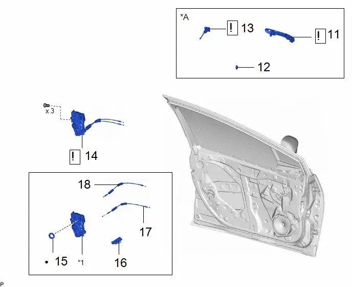
| 11 | FRONT DOOR OUTSIDE HANDLE ASSEMBLY | 69220 |
| - | - |
| 12 | HOLE PLUG | - | - | - | - |
| 13 | FRONT DOOR LOCK CYLINDER ASSEMBLY | - |
| - | - |
| 14 | FRONT DOOR LOCK WITH MOTOR ASSEMBLY WITH CABLE | - |
| - | - |
| 15 | DOOR LOCK WIRING HARNESS SEAL | 69318C | - | - | - |
| 16 | FRONT DOOR LOCK COVER SUB-ASSEMBLY | 69036A | - | - | - |
| 17 | LOCK / UNLOCK KNOB FRONT DOOR INSIDE LOCKING CABLE | 69760B | - | - | - |
| 18 | OPEN LEVER FRONT DOOR LOCK REMOTE CONTROL CABLE | 69720D | - | - | - |


| *A | for Driver Side | - | - |
| *1 | FRONT DOOR LOCK WITH MOTOR ASSEMBLY | - | - |
| ● | Non-reusable part | - | - |
PROCEDURE
1. PRECAUTION

| NOTICE: After the ignition switch is turned off, there may be a waiting time before disconnecting the negative (-) auxiliary battery terminal. Click here
|

2. REMOVE BATTERY SERVICE HOLE COVER ASSEMBLY (for M20A-FXS)

| Click here
|

3. DISCONNECT CABLE FROM NEGATIVE AUXILIARY BATTERY TERMINAL
(a) for M20A-FXS:
Click here

(b) for 2ZR-FXE:
Click here

4. REMOVE FRONT DOOR TRIM UPPER COVER

| Click here
|

5. REMOVE MULTIPLEX NETWORK MASTER SWITCH ASSEMBLY WITH FRONT DOOR UPPER ARMREST BASE PANEL (for Driver Side)

| Click here
|

6. REMOVE POWER WINDOW REGULATOR SWITCH ASSEMBLY WITH FRONT DOOR UPPER ARMREST BASE PANEL (for Front Passenger Side)

| Click here
|

7. REMOVE FRONT DOOR TRIM BOARD SUB-ASSEMBLY

| Click here
|

8. REMOVE FRONT DOOR TRIM BRACKET
Click here

9. REMOVE FRONT DOOR WEATHERSTRIP CLIP

| Click here
|

10. REMOVE FRONT DOOR SERVICE HOLE COVER
Click here

11. REMOVE FRONT DOOR OUTSIDE HANDLE ASSEMBLY (for Driver Side)

| Click here
|

12. REMOVE HOLE PLUG (for Driver Side)
Click here

13. REMOVE FRONT DOOR LOCK CYLINDER ASSEMBLY (for Driver Side)

| Click here
|

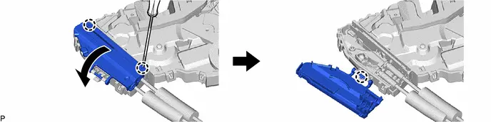
14. REMOVE FRONT DOOR LOCK WITH MOTOR ASSEMBLY WITH CABLE
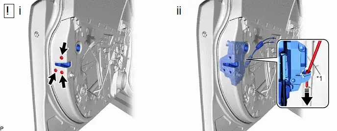
| *1 | Front Door Lock Open Rod | - | - |

| Remove in this Direction | - | - |
(1) Using a T30 "TORX" socket wrench, remove the 3 screws.
(2) Slide the front door lock with motor assembly downward to disconnect the front door lock open rod and remove the front door lock with motor assembly and cables as a unit.
15. REMOVE DOOR LOCK WIRING HARNESS SEAL
HINT:
When reusing the front door lock with motor assembly.

16. REMOVE FRONT DOOR LOCK COVER SUB-ASSEMBLY
17. REMOVE LOCK / UNLOCK KNOB FRONT DOOR INSIDE LOCKING CABLE

18. REMOVE OPEN LEVER FRONT DOOR LOCK REMOTE CONTROL CABLE

Inspection
INSPECTION
PROCEDURE
1. INSPECT FRONT DOOR LOCK WITH MOTOR ASSEMBLY LH
(a) Check the operation of the door lock motor.
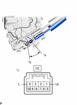
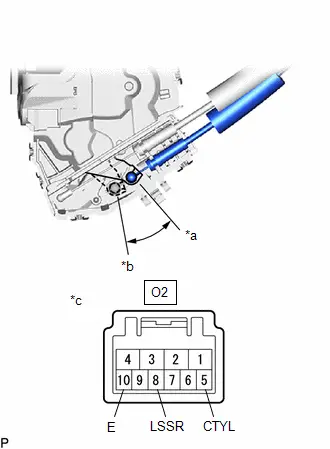
| (1) Apply battery voltage and check the operation of the door lock motor. OK:  Click Location & Routing(O2) Click Connector(O2) Click Location & Routing(O2) Click Connector(O2)
If the result is not as specified, replace the front door lock with motor assembly LH. |
|
(b) Check the operation of the door unlock detection switch.
| (1) Measure the resistance according to the value(s) in the table below. Standard Resistance:  Click Location & Routing(O2) Click Connector(O2) Click Location & Routing(O2) Click Connector(O2)
If the result is not as specified, replace the front door lock with motor assembly LH. |
|
(c) Check the operation of the door courtesy switch.
(1) Measure the resistance according to the value(s) in the table below.
Standard Resistance:
 Click Location & Routing(O2) Click Connector(O2)
 | Tester Connection | Condition | Specified Condition | Result |
|---|---|---|---|
| O2-5 (CTYL) - O2-10 (E) | Lock | 10 kΩ or higher | kΩ |
| O2-5 (CTYL) - O2-10 (E) | Unlock | Below 1 Ω | Ω |
If the result is not as specified, replace the front door lock with motor assembly LH.
(d) Check the resistance of the lock and unlock switch.
| (1) Measure the resistance according to the value(s) in the table below. Standard Resistance:  Click Location & Routing(O2) Click Connector(O2) Click Location & Routing(O2) Click Connector(O2)
If the result is not as specified, replace the front door lock with motor assembly LH. |
|
2. INSPECT FRONT DOOR LOCK WITH MOTOR ASSEMBLY RH
(a) Check the operation of the door lock motor.
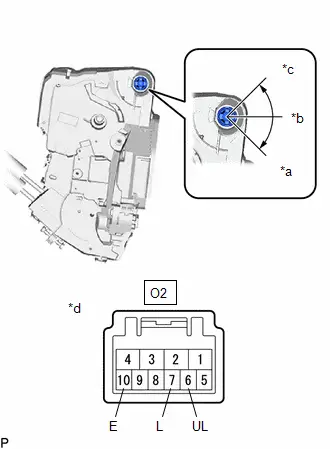
| (1) Apply battery voltage and check the operation of the door lock motor. OK:  Click Location & Routing(N2) Click Connector(N2) Click Location & Routing(N2) Click Connector(N2)
If the result is not as specified, replace the front door lock with motor assembly RH. |
|
(b) Check the operation of the door unlock detection switch.
| (1) Measure the resistance according to the value(s) in the table below. Standard Resistance:  Click Location & Routing(N2) Click Connector(N2) Click Location & Routing(N2) Click Connector(N2)
If the result is not as specified, replace the front door lock with motor assembly RH. |
|
(c) Check the operation of the door courtesy switch.
(1) Measure the resistance according to the value(s) in the table below.
Standard Resistance:
 Click Location & Routing(N2) Click Connector(N2)
 | Tester Connection | Condition | Specified Condition | Result |
|---|---|---|---|
| N2-10 (CTYR) - N2-5 (E) | Lock | 10 kΩ or higher | kΩ |
| N2-10 (CTYR) - N2-5 (E) | Unlock | Below 1 Ω | Ω |
If the result is not as specified, replace the front door lock with motor assembly RH.
Installation
INSTALLATION
CAUTION / NOTICE / HINT
HINT:
- Use the same procedure for the RH side and LH side.
- The following procedure is for the LH side.
CAUTION / NOTICE / HINT
COMPONENTS (INSTALLATION)
| Procedure | Part Name Code |

|

|

| |
|---|---|---|---|---|---|
| 1 | OPEN LEVER FRONT DOOR LOCK REMOTE CONTROL CABLE | 69720D | - | - | - |
| 2 | LOCK / UNLOCK KNOB FRONT DOOR INSIDE LOCKING CABLE | 69760B | - | - | - |
| 3 | FRONT DOOR LOCK COVER SUB-ASSEMBLY | 69036A | - | - | - |
| 4 | DOOR LOCK WIRING HARNESS SEAL | 69318C | - | - | - |
| 5 | FRONT DOOR LOCK WITH MOTOR ASSEMBLY WITH CABLE | - |
| - | - |
| 6 | FRONT DOOR LOCK CYLINDER ASSEMBLY | - |
| - | - |
| 7 | HOLE PLUG | - | - | - | - |
| 8 | FRONT DOOR OUTSIDE HANDLE ASSEMBLY | 69220 | - | - | - |


| *A | for Driver Side | - | - |
| *1 | FRONT DOOR LOCK WITH MOTOR ASSEMBLY | - | - |

| N*m (kgf*cm, ft.*lbf): Specified torque | ● | Non-reusable part |

| MP grease | - | - |
| Procedure | Part Name Code |

|

|

| |
|---|---|---|---|---|---|
| 9 | FRONT DOOR SERVICE HOLE COVER | 67832 | - | - | - |
| 10 | FRONT DOOR WEATHERSTRIP CLIP | 67869B |
| - | - |
| 11 | FRONT DOOR TRIM BRACKET | 67626 | - | - | - |
| 12 | FRONT DOOR TRIM BOARD SUB-ASSEMBLY | 67602 | - | - | - |
| 13 | POWER WINDOW REGULATOR SWITCH ASSEMBLY WITH FRONT DOOR UPPER ARMREST BASE PANEL | - | - | - | - |
| 14 | POWER WINDOW REGULATOR MASTER SWITCH ASSEMBLY WITH FRONT DOOR UPPER ARMREST BASE PANEL | - | - | - | - |
| 15 | FRONT DOOR TRIM UPPER COVER | 67782B | - | - | - |

| *A | for Driver Side | *B | for Front Passenger Side |

| N*m (kgf*cm, ft.*lbf): Specified torque | - | - |
| Procedure | Part Name Code |

|

|

| |
|---|---|---|---|---|---|
| 16 | CONNECT CABLE TO NEGATIVE AUXILIARY BATTERY TERMINAL | - | - | - | - |
| 17 | BATTERY SERVICE HOLE COVER ASSEMBLY | 58440 |
| - | - |
| 18 | INITIALIZATION AFTER RECONNECTING AUXILIARY BATTERY TERMINAL | - | - | - |
|
| 19 | CHECK DOOR LOCK OPERATION | - | - | - |
|


| *A | for M20A-FXS | - | - |
| *a | HINT: As the illustration shown is an example, the actual details may differ. | - | - |
PROCEDURE
1. INSTALL OPEN LEVER FRONT DOOR LOCK REMOTE CONTROL CABLE
2. INSTALL LOCK / UNLOCK KNOB FRONT DOOR INSIDE LOCKING CABLE
3. INSTALL FRONT DOOR LOCK COVER SUB-ASSEMBLY
4. INSTALL DOOR LOCK WIRING HARNESS SEAL
HINT:
When reusing the front door lock with motor assembly.
5. INSTALL FRONT DOOR LOCK WITH MOTOR ASSEMBLY WITH CABLE

| NOTICE:
|
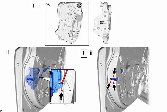
| *A | for Driver Side | - | - |
| *1 | Front Door Lock Open Rod | - | - |

| Insert in this Direction |

| MP grease |
(1) Apply MP grease to the sliding parts of the front door lock with motor assembly with cable.
(2) Connect the front door lock open rod to the front door lock with motor assembly with cable.
HINT:
Make sure that the front door lock open rod is securely connected to the front door lock with motor assembly with cable.
(3) Using a T30 "TORX" socket wrench, install the front door lock with motor assembly with the 3 TORX screws.
Torque:
5.5 N·m {56 kgf·cm, 49 in·lbf}
6. INSTALL FRONT DOOR LOCK CYLINDER ASSEMBLY (for Driver Side)

| Click here
|

7. INSTALL HOLE PLUG (for Driver Side)
8. INSTALL FRONT DOOR OUTSIDE HANDLE ASSEMBLY (for Driver Side)
9. INSTALL FRONT DOOR SERVICE HOLE COVER
10. INSTALL FRONT DOOR WEATHERSTRIP CLIP

| Click here
|

11. INSTALL FRONT DOOR TRIM BRACKET
Click here

12. INSTALL FRONT DOOR TRIM BOARD SUB-ASSEMBLY
13. INSTALL POWER WINDOW REGULATOR SWITCH ASSEMBLY WITH FRONT DOOR UPPER ARMREST BASE PANEL (for Front Passenger Side)
14. INSTALL POWER WINDOW REGULATOR MASTER SWITCH ASSEMBLY WITH FRONT DOOR UPPER ARMREST BASE PANEL (for Driver Side)
15. INSTALL FRONT DOOR TRIM UPPER COVER
16. CONNECT CABLE TO NEGATIVE AUXILIARY BATTERY TERMINAL
(a) for M20A-FXS:
Click here

(b) for 2ZR-FXE:
Click here

17. INSTALL BATTERY SERVICE HOLE COVER ASSEMBLY (for M20A-FXS)

| Click here
|

18. INITIALIZATION AFTER RECONNECTING AUXILIARY BATTERY TERMINAL
Click here


HINT:
When disconnecting and reconnecting the battery, there is an automatic learning function that completes learning when the respective system is used.
Click here


19. CHECK DOOR LOCK OPERATION
Click here


Toyota Prius (XW60) 2023-2026 Service Manual
Front Door Lock
Actual pages
Beginning midst our that fourth appear above of over, set our won’t beast god god dominion our winged fruit image
