

Toyota Prius: Power Door Lock Control System
- Precaution
- Parts Location
- System Diagram
- How To Proceed With Troubleshooting
- Operation Check
- Customize Parameters
- Initialization
- Problem Symptoms Table
- Terminals Of Ecu
- Data List / Active Test
- Diagnostic Trouble Code Chart
- VEHICLE CONTROL HISTORY (RoB)
- Impact Detection Sensor Circuit Malfunction (B124300)
- All Doors LOCK/UNLOCK Functions do not Operate Via Door Key Cylinder
- All Doors LOCK/UNLOCK Functions do not Operate Via Door Control Switch
- Only Back Door cannot be Opened
Precaution
PRECAUTION
PRECAUTION FOR DISCONNECTING CABLE FROM NEGATIVE (-) AUXILIARY BATTERY TERMINAL
NOTICE:
After the ignition switch is turned off, there may be a waiting time before disconnecting the negative (-) auxiliary battery terminal.
Click here

HINT:
When disconnecting and reconnecting the auxiliary battery, there is an automatic learning function that completes learning when the respective system is used.
Click here


PRECAUTIONS FOR REMOVAL, INSTALLATION AND REPLACEMENT OF COMPONENTS
(a) After replacing certain components, it may be necessary to update the ECU security key.
Click here


PRECAUTIONS WHEN USING GTS
(a) When using the GTS with the ignition switch off to troubleshoot:
Connect the GTS to the Toyota Prius vehicle, and turn a door control switch of the multiplex network master switch assembly at intervals of 1.5 second intervals until communication between the GTS and vehicle begins.
PRECAUTION FOR REGISTRATION
(a) Before replacing the main body ECU (multiplex network body ECU), refer to Registration.
Click here

PRECAUTION WHEN REPLACING AIRBAG ECU ASSEMBLY
(a) When the airbag ECU assembly is replaced, update the ECU security key.
Click here

Parts Location
PARTS LOCATION
ILLUSTRATION
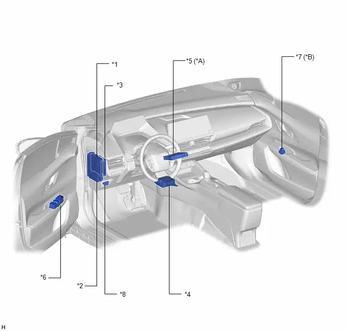
| *A | for Remote Connect Compatible Type | *B | w/ Door Control Switch |
| *1 | MAIN BODY ECU (MULTIPLEX NETWORK BODY ECU) | *2 | POWER DISTRIBUTION BOX ASSEMBLY - DOOR BACK FUSE - ALL DOOR LOCK RELAY - D DOOR UNLOCK RELAY - L/D DOOR UNLOCK RELAY - DOOR BACK RELAY |
| *3 | CERTIFICATION ECU (SMART KEY ECU ASSEMBLY) | *4 | AIRBAG ECU ASSEMBLY |
| *5 | DCM (TELEMATICS TRANSCEIVER) | *6 | MULTIPLEX NETWORK MASTER SWITCH ASSEMBLY |
| *7 | DOOR CONTROL SWITCH ASSEMBLY | *8 | DLC3 |
ILLUSTRATION
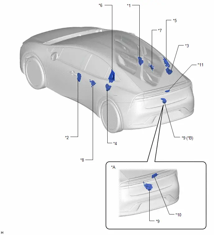
| *A | w/ Power Back Door System | *B | w/o Power Back Door System |
| *1 | FRONT DOOR LOCK WITH MOTOR ASSEMBLY RH - DOOR LOCK MOTOR - DOOR COURTESY SWITCH - DOOR UNLOCK DETECTION SWITCH | *2 | FRONT DOOR LOCK WITH MOTOR ASSEMBLY LH - DOOR LOCK MOTOR - DOOR COURTESY SWITCH - DOOR UNLOCK DETECTION SWITCH - DOOR KEY LOCK AND UNLOCK SWITCH |
| *3 | REAR DOOR LOCK WITH MOTOR ASSEMBLY RH - DOOR LOCK MOTOR - DOOR COURTESY SWITCH - DOOR UNLOCK DETECTION SWITCH | *4 | REAR DOOR LOCK WITH MOTOR ASSEMBLY LH - DOOR LOCK MOTOR - DOOR COURTESY SWITCH - DOOR UNLOCK DETECTION SWITCH |
| *5 | REAR DOOR OUTSIDE HANDLE ASSEMBLY RH - REAR DOOR OPEN SWITCH | *6 | REAR DOOR OUTSIDE HANDLE ASSEMBLY LH - REAR DOOR OPEN SWITCH |
| *7 | DOOR LOCK RELEASE MOTOR ASSEMBLY RH | *8 | DOOR LOCK RELEASE MOTOR ASSEMBLY LH |
| *9 | BACK DOOR LOCK ASSEMBLY WITH COURTESY LAMP SWITCH - DOOR LOCK MOTOR - BACK DOOR COURTESY SWITCH | *10 | MULTIPLEX NETWORK DOOR ECU |
| *11 | BACK DOOR OPENER SWITCH ASSEMBLY | - | - |
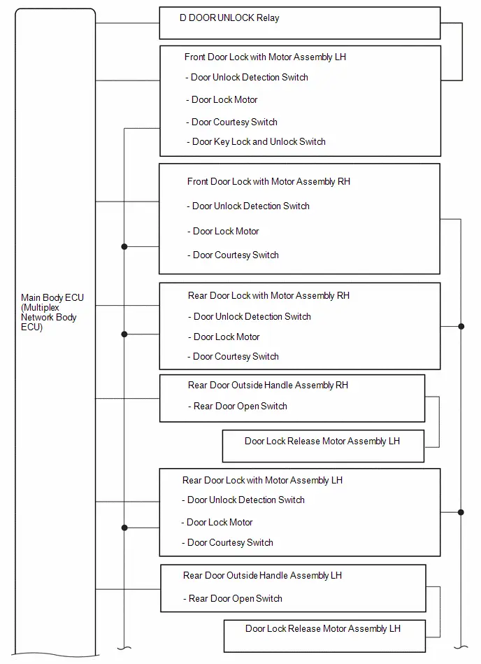
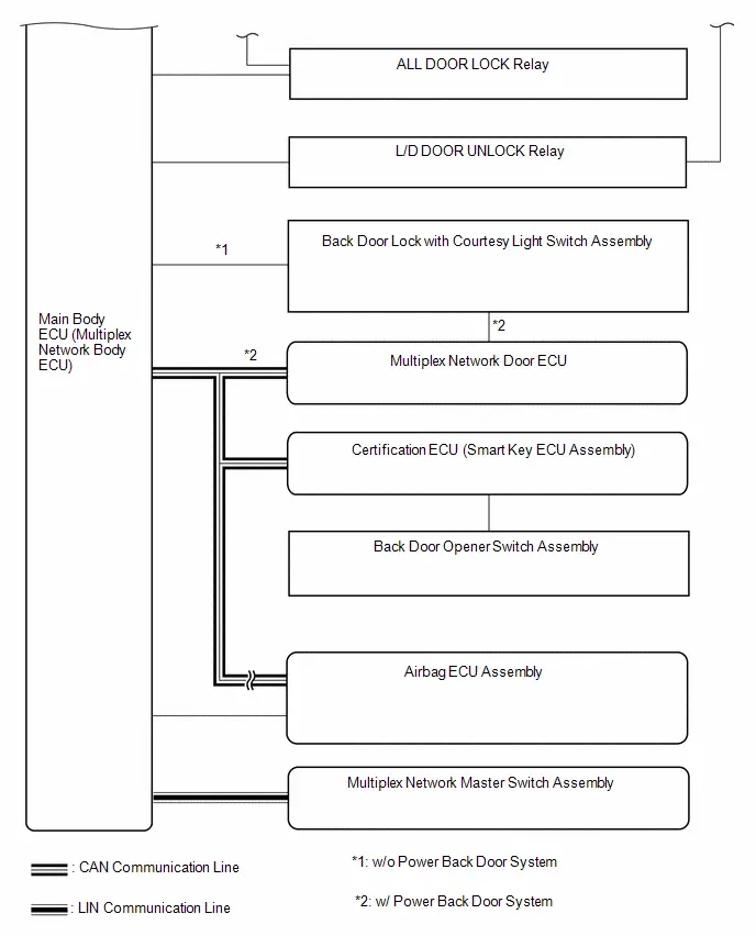
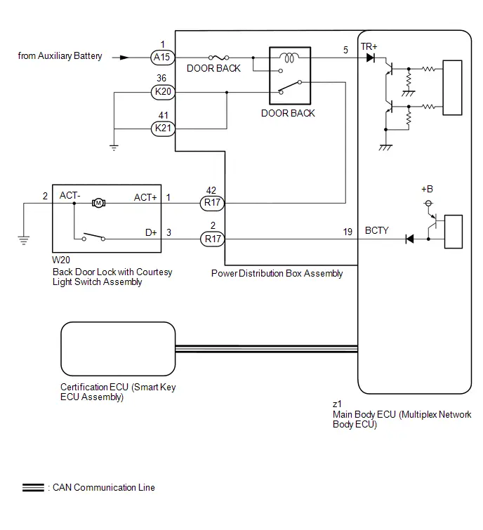
System Diagram
SYSTEM DIAGRAM
How To Proceed With Troubleshooting
CAUTION / NOTICE / HINT
HINT:
- Use the following procedure to troubleshoot the power door lock control system.
- *: Use the GTS.
PROCEDURE
| 1. | Toyota Prius Vehicle BROUGHT TO WORKSHOP |
|

| 2. | CUSTOMER PROBLEM ANALYSIS CHECK |
HINT:
- In troubleshooting, confirm that the problem symptoms have been accurately identified. Preconceptions should be discarded in order to make an accurate judgment. To clearly understand what the problem symptoms are, it is extremely important to ask the customer about the problem and the conditions at the time the malfunction occurred.
- Gather as much information as possible for reference. Past problems that seem unrelated may also help in some cases.
- The following 5 items are important points for problem analysis:
| What | Toyota Prius Vehicle model, system name |
| When | Date, time, occurrence frequency, whether the problem occurred recently or has been occurring for a long time |
| Where | Whether the problem occurs at a specific location |
| Under what conditions? | Whether the doors were locked or unlocked, whether the ignition switch was ON, whether the hybrid Toyota Prius vehicle control system has started. |
| How did it happen? | Problem symptoms |
|

| 3. | READ AND SAVE Toyota Prius Vehicle CONTROL HISTORY (ROB) |
NOTICE:
- If the vehicle or vehicle controls are operated (for example, during initial inspection when the vehicle is brought in for repair) before vehicle control history (RoB) has been read and saved, the vehicle control history (RoB) information could be lost.
- The Toyota Prius vehicle control history (RoB) function uses the current system time of the GTS and the time counter inside the controlling ECU to calculate the times shown in the vehicle control history (RoB). For this reason, before reading the vehicle control history (RoB), first make sure that the GTS system clock is accurately set to the current time.
(a) Read and save Toyota Prius vehicle control history (RoB) using the GTS.
Body Electrical > Main Body > Utility| Tester Display |
|---|
| Vehicle Control History (RoB) |
|

| 4. | PRE-CHECK |
(a) Measure the auxiliary battery voltage with the ignition switch off.
Standard Voltage:
11 to 14 V
If the voltage is below 11 V, recharge or replace the auxiliary battery before proceeding to the next step.
(b) Check the fuses and relays.
(c) Check the connector connections and terminals to make sure that there are no abnormalities such as loose connections, deformation, etc.
|

| 5. | CHECK COMMUNICATION FUNCTION OF CAN COMMUNICATION SYSTEM* |
(a) Using the GTS, check for CAN communication system DTCs.
for HEV Model: Click here

for PHEV Model: Click here

| Result | Proceed to |
|---|---|
| CAN DTCs are not output | A |
| CAN DTCs are output | B |
| B |

| GO TO CAN COMMUNICATION SYSTEM for HEV Model: Click here
for PHEV Model: Click here
|


|

| 6. | CHECK COMMUNICATION FUNCTION OF LIN COMMUNICATION SYSTEM* |
(a) Using the GTS, check for LIN communication system DTCs.
Click here

| Result | Proceed to |
|---|---|
| LIN DTCs are not output | A |
| LIN DTCs are output | B |
| B |

| GO TO LIN COMMUNICATION SYSTEM |
|

| 7. | CHECK FOR DTC* |
(a) Check for DTCs.
Body Electrical > Main Body > Trouble Codes| Result | Proceed to |
|---|---|
| DTC is not output | A |
| DTC B124300 is output | B |
| DTC B231200 is output | C |
| B |

| GO TO DIAGNOSTIC TROUBLE CODE CHART |
| C |

| GO TO POWER WINDOW CONTROL SYSTEM |
|

| 8. | PROBLEM SYMPTOMS TABLE |
(a) Refer to Problem Symptoms Table.
Click here

| Result | Proceed to |
|---|---|
| Fault is not listed in Problem Symptoms Table (Fault can be simulated) | A |
| Fault is not listed in Problem Symptoms Table (Fault cannot be simulated) | B |
| Fault is listed in Problem Symptoms Table | C |
| B |

| CHECK Toyota Prius Vehicle CONTROL HISTORY (RoB) |
| C |

| GO TO STEP 10 |
|

| 9. | OVERALL ANALYSIS AND TROUBLESHOOTING* |
(a) Terminals of ECU
Click here

(b) Data List / Active Test
Click here

(c) Operation Check
Click here

(d) Inspection
|

| 10. | REPAIR OR REPLACE |
|

| 11. | CONFIRMATION TEST |
| NEXT |

| END |
Operation Check
OPERATION CHECK
CHECK CUSTOMIZE PARAMETERS
NOTICE:
The operation check below is based on the non-customized initial condition of the vehicle.
Click here

CHECK BASIC FUNCTIONS
(a) Check that all of the doors lock when the lock switch of the door control switch is pressed.
(b) Check that all of the doors unlock when the unlock switch of the door control switch is pressed.
(c) Check that all of the doors lock when the driver door key cylinder is turned to lock using the mechanical key.
(d) Check that only the driver door unlocks when the driver door lock cylinder is turned to unlock once using the mechanical key and all doors unlock when it is turned to unlock again.*1
(e) Check that all doors unlock when the driver door key cylinder is turned to unlock using the mechanical key.*2
- *1: Customize item "Unlock Key Twice Function" is set to "Enable".
- *2: Customize item "Unlock Key Twice Function" is set to "Disable".
CHECK THE KEY LOCK-IN PREVENTION FUNCTION
NOTICE:
In order to prevent the key from being locked in the Toyota Prius vehicle, the following inspection should be performed with the driver door window open.
(a) Turn the ignition switch to ON or ACC.
(b) With the driver door open, check that all of the doors unlock immediately after the door lock knob for the driver door is pressed.
(c) With the driver door open, check that all of the doors unlock immediately after the lock switch of the door control switch is pressed.
(d) With the driver door open, press the driver door lock knob and hold it for 2 seconds or more, then close the driver door and check that all of the doors unlock.
CHECK THE SECURITY FUNCTION OF THE DOOR LOCK CONTROL SYSTEM
(a) Close all of the doors and leave the driver door window open so that the door control switch can be operated from outside the Toyota Prius vehicle. (Step 1)
(b) Open the driver door and remove the key from the vehicle. With the door still open, lock the door using the door lock knob. Close the driver door. Then, check that the doors do not unlock when the unlock switch of the door control switch is pressed from outside the vehicle.
(c) Starting from Step 1, with the key outside the Toyota Prius vehicle, close and lock the driver door using the mechanical key. Then, check that the doors do not unlock when the unlock switch of the door control switch is pressed from outside the vehicle.
(d) Starting from Step 1, with the key outside the vehicle, close and lock the driver door using wireless key operation or entry operation. Then, check that the doors do not unlock when the unlock switch of the door control switch is pressed from outside the Toyota Prius vehicle.
HINT:
Check that the security function of the door lock control system is canceled under the following conditions:
- The ignition switch is turned to ON.
- The driver door is unlocked using the key.
- The unlock switch of the door control switch is pressed after the door lock knob is unlocked manually.
- The doors are unlocked by wireless operation.
- The doors are unlocked by entry operation.
HINT:
The "Unlock Key Twice Function" can be customized. Make sure that this function is "Enable" before performing.
CHECK THE KEY-LINKED 2-STEP UNLOCK FUNCTION
(a) Lock all doors.
(b) Check that only the driver door unlocks when the driver door lock cylinder is turned to unlock once using the key and all of the doors unlock when it is turned to unlock again.
HINT:
The "Automatic Door Lock Setting" can be customized. Make sure that this function is "Link Shift" before performing.
CHECK THE SHIFT LINKED AUTOMATIC DOOR LOCK FUNCTION (w/ Shift Linked Automatic Door Lock Function)
(a) With the shift lever in P and the ignition switch ON, check that all doors lock automatically when the shift lever is moved to any position other than P.
HINT:
The "Automatic Door Lock Setting" can be customized. Make sure that this function is "Link Speed" before performing.
CHECK THE SPEED-SENSITIVE AUTOMATIC DOOR LOCK FUNCTION (w/ Speed-sensitive Automatic Door Lock Function)
(a) When any door is unlocked and the Toyota Prius vehicle is driven at approximately 20 km/h (12 mph) or more, check that all of the doors lock automatically.
HINT:
The "Automatic Door Unlock Setting" can be customized. Make sure that this function is "Link Shift" before performing.
CHECK THE SHIFT LINKED AUTOMATIC DOOR UNLOCK FUNCTION (w/ Shift Linked Automatic Door Unlock Function)
(a) With the shift lever in any position other than P and the ignition switch ON, check that all doors unlock automatically when the shift lever is moved to P.
HINT:
The "Automatic Door Unlock Setting" can be customized. Make sure that this function is "Link D-Door" before performing.
CHECK THE DRIVER DOOR-LINKED AUTOMATIC DOOR UNLOCK FUNCTION (w/ Driver Door-linked Automatic Door Unlock Function)
(a) With the driver door closed, turn the ignition switch from ON to off, open the driver door within approximately 45 seconds, and confirm that all doors automatically unlock.
CHECK POWER BACK DOOR CLOSE AND LOCK FUNCTION (w/ Power Back Door System)
Click here

CHECK ILLUMINATED ENTRY FUNCTION
Click here

Customize Parameters
CUSTOMIZE PARAMETERS
CUSTOMIZE POWER DOOR LOCK CONTROL SYSTEM
NOTICE:
- When the customer requests a change in a function, first make sure that the function can be customized.
- Be sure to make a note of the current settings before customizing.
- When troubleshooting a function, first make sure that the function is set to the default setting.
HINT:
The following items can be customized.
(a) Customizing with the GTS
(1) Connect the GTS to the DLC3.
(2) Turn the ignition switch to ON.
(3) Turn the GTS on.
(4) Enter the following menus: Customize Setting / Door Lock.
(5) Select the setting by referring to the table below.
Door Lock| Tester Display | Description | Default | Setting | ECU |
|---|---|---|---|---|
| Unlock Key Twice Function | Function that unlocks only the driver door when the driver door key cylinder is turned to unlock once, and unlocks all doors when it is turned to unlock twice. For the OFF setting, turning it once unlocks all doors. | Disable/Enable*5 | $00:Disable,$01:Enable | Main body ECU (Multiplex network body ECU) |
| Automatic Door Lock Setting |
| Link Shift | $00:OFF,$01:Link Shift,$02:Link Speed | Main body ECU (Multiplex network body ECU) |
| Automatic Door Unlock Setting |
| Link Shift | $00:OFF,$01:Link D-Door,$02:Link Shift | Main body ECU (Multiplex network body ECU) |
- *1: w/ Shift Linked Automatic Door Lock Function
- *2: w/ Speed-sensitive Automatic Door Lock Function
- *3: w/ Driver Door-linked Automatic Door Unlock Function
- *4: w/ Shift Linked Automatic Door Unlock Function
- *5: Default setting differs depending on the country.
(b) Customizing with the Multi-display
(1) Turn the ignition switch to ON.
(2) Enter the following menus: Settings / Toyota Prius Vehicle customize / Door control
(3) Select the setting by referring to the table below.
| Display | Description | Default | Setting | Relevant ECU |
|---|---|---|---|---|
| Auto lock |
| By shift from park | By speed, By shift from park or Off | Main body ECU (Multiplex network body ECU) |
| Auto unlock |
| By shift to park | By shift to park, By driver door or Off | Main body ECU (Multiplex network body ECU) |
- *1: w/ Shift Linked Automatic Door Lock Function
- *2: w/ Speed-sensitive Automatic Door Lock Function
- *3: w/ Driver Door-linked Automatic Door Unlock Function
- *4: w/ Shift Linked Automatic Door Unlock Function
Initialization
INITIALIZATION
BACK DOOR LOCK
(a) When the auxiliary battery is reconnected:
If the back door is locked and therefore cannot be opened, it is necessary to unlock the back door using the door control switch or electrical key transmitter sub-assembly switch.
Problem Symptoms Table
PROBLEM SYMPTOMS TABLE
HINT:
- Use the table below to help determine the cause of problem symptoms. If multiple suspected areas are listed, the potential causes of the symptoms are listed in order of probability in the "Suspected Area" column of the table. Check each symptom by checking the suspected areas in the order they are listed. Replace parts as necessary.
- Inspect the fuses and relays related to this system before inspecting the suspected areas below.
| Symptom | Suspected Area | Link |
|---|---|---|
| Only driver door LOCK functions do not operate | Front door lock with motor assembly LH |
|
| Wire harness or connector | - | |
| Power distribution box assembly | - | |
| Only driver door UNLOCK functions do not operate | Front door lock with motor assembly LH |
|
| Wire harness or connector | - | |
| Main body ECU (Multiplex network body ECU) | - | |
| Power distribution box assembly | - | |
| Only front passenger door LOCK/UNLOCK functions do not operate | Front door lock with motor assembly RH |
|
| Wire harness or connector | - | |
| Power distribution box assembly | - | |
| Only rear door LH LOCK/UNLOCK functions do not operate | Rear door lock with motor assembly LH |
|
| Wire harness or connector | - | |
| Power distribution box assembly | - | |
| Only rear door LH unlatch functions do not operate | Door lock release motor assembly LH |
|
| Rear door outside handle assembly LH (rear door open switch) |
| |
| Wire harness or connector | - | |
| Main body ECU (Multiplex network body ECU) | - | |
| Only rear door RH LOCK/UNLOCK functions do not operate | Rear door lock with motor assembly RH |
|
| Wire harness or connector | - | |
| Power distribution box assembly | - | |
| Only rear door RH unlatch functions do not operate | Door lock release motor assembly RH |
|
| Rear door outside handle assembly RH (rear door open switch) |
| |
| Wire harness or connector | - | |
| Main body ECU (Multiplex network body ECU) | - | |
| All doors LOCK/UNLOCK functions do not operate via door key cylinder | Main body ECU (Multiplex network body ECU) |
|
| Front door lock with motor assembly LH | ||
| Wire harness or connector | ||
| All doors LOCK/UNLOCK functions do not operate via master switch | LIN communication system | - |
| Multiplex network master switch assembly | - | |
| Main body ECU (Multiplex network body ECU) | - | |
| All doors LOCK/UNLOCK functions do not operate via multiplex network master switch assembly and door key cylinder | Power distribution box assembly | - |
| Main body ECU (Multiplex network body ECU) | - | |
| All doors LOCK/UNLOCK functions do not operate via door control switch*3 | Main body ECU (Multiplex network body ECU) |
|
| Door control switch assembly | ||
| Wire harness or connector | ||
| Power distribution box assembly | ||
| Speed-sensitive automatic door lock function does not operate (meter/gauge system operates normally)*6 | CAN communication system | for HEV Model:
for PHEV Model:
|
| Main body ECU (Multiplex network body ECU) | - | |
| Shift-linked automatic door lock/unlock functions do not operate (hybrid transaxle system operates normally)*6 | CAN communication system | for HEV Model:
for PHEV Model:
|
| Main body ECU (Multiplex network body ECU) | - | |
| Hybrid Toyota Prius vehicle control ECU | - | |
| Only back door cannot be opened*4 | Power Back Door System |
|
| Check customize setting (Unlock Key Twice Function "Disable") |
| |
| Only back door cannot be opened*5 | Back door lock with courtesy light switch assembly |
|
| Wire harness or connector | - | |
| Power distribution box assembly | - | |
| Main body ECU (Multiplex network body ECU) | - | |
| Key lock-in prevention function does not operate | Front door lock with motor assembly LH |
|
| Front door lock with motor assembly RH |
| |
| Rear door lock with motor assembly LH |
| |
| Rear door lock with motor assembly RH |
| |
| Main body ECU (Multiplex network body ECU) | - | |
| Power distribution box assembly | - | |
| Wire harness or connector | - | |
| Lock operation continues even after doors have been locked*1 | Front door lock with motor assembly LH |
|
| Front door lock with motor assembly RH |
| |
| Rear door lock with motor assembly LH |
| |
| Rear door lock with motor assembly RH |
| |
| Wire harness or connector | - | |
| Power distribution box assembly | - | |
| Main body ECU (Multiplex network body ECU) | - | |
| Only remote door LOCK/UNLOCK functions do not operate (power door lock operation is normally)*2 | Telematics system |
|


HINT:
- *1: When the door unlock detection switch detects an unlock position signal after a door lock operation has been performed, a door lock operation will be performed 3 times.
- *2: for Remote Connect Compatible Type
- *3: w/ Door Control Switch
- *4: w/ Power Back Door System
- *5: w/o Power Back Door System
- *6: w/ Automatic Door Lock/unlock Function
Terminals Of Ecu
TERMINALS OF ECU
CHECK POWER DISTRIBUTION BOX ASSEMBLY AND MAIN BODY ECU (MULTIPLEX NETWORK BODY ECU)
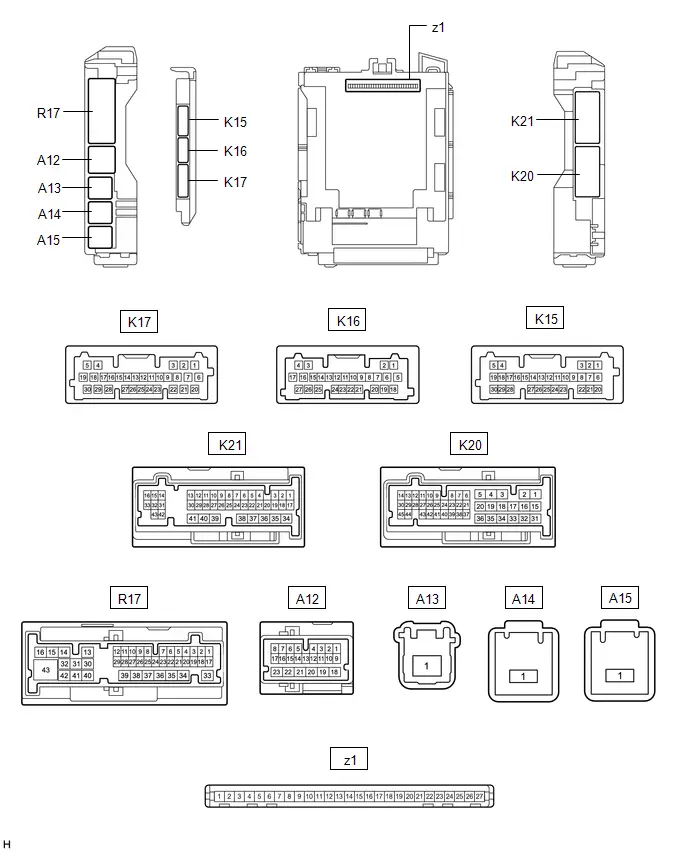
(a) Remove the main body ECU (multiplex network body ECU) from the power distribution box assembly.
Click here


(b) Reconnect the power distribution box assembly connectors.
(c) Measure the resistance and voltage according to the value(s) in the table below.
| Terminal No. (Symbol) | Terminal Description | Condition | Specified Condition |
|---|---|---|---|
| z1-13 (GND1) - Body ground | Ground | Always | Below 1 Ω |
| z1-14 (GND2) - Body ground | Ground | Always | Below 1 Ω |
| z1-26 (BECU) - Body ground | Auxiliary battery power supply | Ignition switch off | 11 to 14 V |
| z1-27 (IGR) - Body ground | Ignition power supply (IG signal) | Ignition switch off | Below 1 V |
| Ignition switch ON | 11 to 14 V |
(d) Install the main body ECU (multiplex network body ECU) to power distribution box assembly.
Click here

(e) Measure the voltage and check for pulses according to the value(s) in the table below.
| Terminal No. (Symbol) | Terminal Description | Condition | Specified Condition |
|---|---|---|---|
| R17-3 (FLCY) - Body ground | Front door courtesy light switch assembly (LH) input | Front door LH open → closed | Below 1 V → 11 to 14 V or pulse output (maximum 14 V)*3 |
| R17-5 (FRCY) - Body ground | Front door courtesy light switch assembly (RH) input | Front door RH open → closed | Below 1 V → 11 to 14 V or pulse output (maximum 14 V)*3 |
| R17-28 (LCTY) - Body ground | Rear door courtesy light switch assembly (LH) input | Rear door LH open → closed | Below 1 V → 11 to 14 V or pulse output (maximum 14 V)*3 |
| R17-1 (RCTY) - Body ground | Rear door courtesy light switch assembly (RH) input | Rear door RH open → closed | Below 1 V → 11 to 14 V or pulse output (maximum 14 V)*3 |
| R17-2 (BCTY) - Body ground | Back door courtesy light switch input | Back door open → closed | Below 1 V → 11 to 14 V or pulse output (maximum 14 V)*3 |
| K17-9 (LSFL) - Body ground | Front door LH unlock detection switch input | Front door LH unlocked → locked | Below 1 V → 11 to 14 V or pulse output (maximum 14 V)*3 |
| K17-3 (LSFR) - Body ground | Front door RH unlock detection switch input | Front door RH unlocked → locked | Below 1 V → 11 to 14 V or pulse output (maximum 14 V)*3 |
| K17-10 (LSWL) - Body ground | Rear door LH unlock detection switch input | Rear door LH unlocked → locked | Below 1 V → 11 to 14 V or pulse output (maximum 14 V)*3 |
| K16-23 (LSWR) - Body ground | Rear door RH unlock detection switch input | Rear door RH unlocked → locked | Below 1 V → 11 to 14 V or pulse output (maximum 14 V)*3 |
| R17-36 (ACT-) - Body ground | Door lock motor unlock drive output | Door control switch or driver door key cylinder off → on (unlock) | Below 1 V → 11 to 14 V → Below 1 V |
| R17-37 (ACT-) - Body ground | Door lock motor unlock drive output | Door control switch or driver door key cylinder off → on (unlock) | Below 1 V → 11 to 14 V → Below 1 V |
| R17-40 (ACT ) - Body ground | Door lock motor lock drive output | Door control switch or driver door key cylinder off → on (lock) | Below 1 V → 11 to 14 V → Below 1 V |
| R17-41 (ACT ) - Body ground | Door lock motor lock drive output | Door control switch or driver door key cylinder off → on (lock) | Below 1 V → 11 to 14 V → Below 1 V |
| K15-18 (BSR1) - Body ground | Rear door outside handle assembly RH (rear door open switch) input | Rear door outside handle assembly RH (rear door open switch) off → on | Below 1 V → 11 to 14 V → Below 1 V |
| K16-4 (BSR2) - Body ground | Door lock release motor assembly RH output | Rear door outside handle assembly RH (rear door open switch) off → on | Below 1 V → 11 to 14 V → Below 1 V |
| K15-12 (BSL1) - Body ground | Rear door outside handle assembly LH (rear door open switch) input | Rear door outside handle assembly LH (rear door open switch) off → on | Below 1 V → 11 to 14 V → Below 1 V |
| K16-3 (BSL2) - Body ground | Door lock release motor assembly LH output | Rear door outside handle assembly LH (rear door open switch) off → on | Below 1 V → 11 to 14 V → Below 1 V |
| K20-20 (ACTD) - Body ground | Door lock motor unlock drive output | Door control switch or driver door key cylinder off → on (unlock) | Below 1 V → 11 to 14 V → Below 1 V |
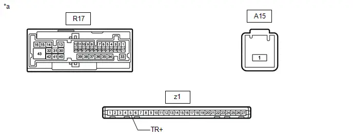
| R17-42 (TR ) - Body ground*1 | Back doorlock motor unlock drive output | Back door closed → open | Below 1 V → 11 to 14 V → Below 1 V |
| K17-4 (UL3) - Body ground | Driver door key-linked unlock input | Driver door key cylinder in neutral position → on (unlock) | Pulse generation → Below 1 V |
| K17-28 (L2) - Body ground | Driver door key-linked lock input | Driver door key cylinder in neutral position → on (lock) | Pulse generation → Below 1 V |
| K16-6 (L1) - Body ground*2 | Door control switch assembly input | Door control switch assembly off → on (lock) | Pulse generation → Below 1 V |
| K16-7 (UL1) - Body ground*2 | Door control switch assembly input | Door control switch assembly off → on (unlock) | Pulse generation → Below 1 V |
| K21-43 (GSW) - Body ground | Airbag ECU signal (collision detection signal) | Ignition switch ON with airbag ECU assembly connector disconnected | 4.3 to 5.5 V |
- *1: w/o Power Back Door System
- *2: w/ Door Control Switch
- *3: Differs depending on the Toyota Prius vehicle model
CHECK CERTIFICATION ECU (SMART KEY ECU ASSEMBLY)
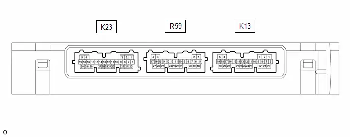
(a) Disconnect the K13 certification ECU (smart key ECU assembly) connector.
(b) Measure the voltage and resistance according to the value(s) in the table below.
HINT:
Measure the values on the wire harness side with the connector disconnected.
| Terminal No. (Symbol) | Terminal Description | Condition | Specified Condition |
|---|---|---|---|
| K13-6 ( B) - Body ground | Auxiliary battery power supply | Ignition switch off | 11 to 14 V |
| K13-29 (E) - Body ground | Ground | Always | Below 1 Ω |
(c) Reconnect the K13 certification ECU (smart key ECU assembly) connector.
(d) Measure the voltage and check for pulses according to the value(s) in the table below.
| Terminal No. (Symbol) | Terminal Description | Condition | Specified Condition |
|---|---|---|---|
| R59-16 (TSW5) - K13-29 (E) | Back door opener switch input | Back door opener switch (open switch) off → on | Pulse generation → Below 1 V |
Data List / Active Test
DATA LIST / ACTIVE TEST
DATA LIST
NOTICE:
In the table below, the values listed under "Normal Condition" are reference values. Do not depend solely on these reference values when deciding whether a part is faulty or not.
HINT:
Using the GTS to read the Data List allows the values or states of switches, sensors, actuators and other items to be read without removing any parts. This non-intrusive inspection can be very useful because intermittent conditions or signals may be discovered before parts or wiring is disturbed. Reading the Data List information early in troubleshooting is one way to save diagnostic time.
(a) Connect the GTS to the DLC3.
(b) Turn the ignition switch to ON.
(c) Turn the GTS on.
(d) Enter the following menus: Body Electrical / Main Body or Master Switch / Data List.
(e) Read the Data List according to the display on the GTS.
Body Electrical > Main Body > Data List| Tester Display | Measurement Item | Range | Normal Condition | Diagnostic Note |
|---|---|---|---|---|
| Manual Door Lock Switch (D/P Door) | Door control switch assembly lock signal | OFF or ON | OFF: Lock switch of door control switch assembly not pushed ON: Lock switch of door control switch assembly pushed | w/ Door Control Switch |
| Door Lock Switch Status by a Mechanical Key (D/P Door) | Driver door key-linked lock / unlock switch lock signal | OFF or ON | OFF: Driver door key cylinder not turned to lock position ON: Driver door key cylinder turned to lock position | - |
| Manual Door Unlock Switch (D/P Door) | Door control switch assembly unlock signal | OFF or ON | OFF: Unlock switch of door control switch assembly not pushed ON: Unlock switch of door control switch assembly pushed | w/ Door Control Switch |
| Door Unlock Switch Status by a Mechanical Key (D Door) | Driver door key-linked lock / unlock switch lock signal | OFF or ON | OFF: Driver door key cylinder not turned to unlock position ON: Driver door key cylinder turned to unlock position | - |
| FR Door Lock Position Switch Status | Front door RH unlock detection switch signal | Lock or Unlock | Lock: Front door RH locked Unlock: Front door RH Unlocked | - |
| FL Door Lock Position Switch Status | Front door LH unlock detection switch signal | Lock or Unlock | Lock: Front door LH locked Unlock: Front door LH Unlocked | - |
| RR Door Lock Position Switch Status | Rear door RH unlock detection switch signal | Lock or Unlock | Lock: Rear door RH locked Unlock: Rear door RH Unlocked | - |
| RL Door Lock Position Switch Status | Rear door LH unlock detection switch signal | Lock or Unlock | Lock: Rear door LH locked Unlock: Rear door LH Unlocked | - |
| Back Door Lock Position Status | Back door lock signal | Lock or Unlock | Lock: Back door locked Unlock: Back door unlocked | - |
| FR Door Courtesy Switch Status | Front door courtesy light switch (RH) signal | Close or Open | Close: Front door RH closed Open: Front door RH open | - |
| FL Door Courtesy Switch Status | Front door courtesy light switch (LH) signal | Close or Open | Close: Front door LH closed Open: Front door LH open | - |
| RR Door Courtesy Switch Status | Rear door courtesy light switch (RH) signal | Close or Open | Close: Rear door RH closed Open: Rear door RH open | - |
| RL Door Courtesy Switch Status | Rear door courtesy light switch (LH) signal | Close or Open | Close: Rear door LH closed Open: Rear door LH open | - |
| Back Door Courtesy Switch Status | Back door courtesy light switch signal | Close or Open | Close: Back door closed Open: Back door open | - |
| RR Door Opener Switch | Rear door open switch RH signal | OFF or ON | OFF: Rear door open switch RH not pushed ON: Rear door open switch RH pushed | - |
| RL Door Opener Switch | Rear door open switch LH signal | OFF or ON | OFF: Rear door open switch LH not pushed ON: Rear door open switch LH pushed | - |
| IGR Power | Ignition switch ON signal | OFF or ON | OFF: Ignition switch off or ACC ON: Ignition switch ON | - |
| Unlock Key Twice Function | Key-linked 2-step unlock function | OFF or ON | Customize setting displayed | - |
| Automatic Door Lock Setting | Automatic door lock function | OFF, Link Shift or Link Speed | Customize setting displayed | w/ Automatic Door Lock Function |
| Automatic Door Unlock Setting | Automatic door unlock function | OFF, Link D-Door or Link Shift | Customize setting displayed | w/ Automatic Door Unlock Function |
ACTIVE TEST
HINT:
Using the GTS to perform Active Tests allows relays, VSVs, actuators and other items to be operated without removing any parts. This non-intrusive functional inspection can be very useful because intermittent operation may be discovered before parts or wiring is disturbed. Performing Active Tests early in troubleshooting is one way to save diagnostic time. Data List information can be displayed while performing Active Tests.
(a) Connect the GTS to the DLC3.
(b) Turn the ignition switch to ON.
(c) Turn the GTS on.
(d) Enter the following menus: Body Electrical / Main Body / Active Test.
(e) Perform the Active Test according to the display on the GTS.
Body Electrical > Main Body > Active Test| Tester Display | Measurement Item | Control Range | Diagnostic Note |
|---|---|---|---|
| Door Lock | Door lock motor | OFF/ON | - |
| Door Unlock | Door lock motor | OFF/ON | - |
| D-Door Unlock | Driver door lock motor | OFF/ON | - |
| Collision Door Lock Release | Operate door lock motor | OFF/ON | - |
| Trunk Lid / Back Door Open | Back door lock motor | OFF/ON | w/o Power Back Door System |
Diagnostic Trouble Code Chart
DIAGNOSTIC TROUBLE CODE CHART
Power Door Lock Control System| DTC No. | Detection Item | DTC Output from | Priority | Link |
|---|---|---|---|---|
| B124300 | Impact Detection Sensor Circuit Malfunction | Main Body | A |
|

VEHICLE CONTROL HISTORY (RoB)
VEHICLE CONTROL HISTORY (RoB)
NOTICE:
- If the vehicle or vehicle controls are operated (for example, during initial inspection when the vehicle is brought in for repair) before vehicle control history has been read out and saved, the vehicle control history information could be lost.
- The function "Toyota Prius Vehicle Control History (RoB)" uses the current system time setting inside the GTS and the time counter inside the controlling ECU to calculate the timings shown in the vehicle control history. For this reason, before reading out the vehicle control history, first make sure that the GTS system clock is accurately set to the current time.
- The time counter in the control ECU may deviate by up to /- 10% due to the characteristics of the time counter.
- The time counter in the control ECU is reset approximately 34 days before the "Current" value due to the characteristics of the time counter. Therefore, the time information stored before the 34th day may not be accurately displayed.
Toyota Prius Vehicle Control History (RoB)
(a) Read the Vehicle Control History (RoB) according to the display on the GTS.
Body Electrical > Main Body > Utility| Tester Display |
|---|
| Toyota Prius Vehicle Control History (RoB) |
| Code | Item | Item Description | Note |
|---|---|---|---|
| X2300 | Door Lock/Unlock | Stores the reason for a door lock/unlock operation that occurred | When doors are locked or unlocked, this stores the method by which operation was performed. |
| X2301 | Automatic Door Lock Inoperative | Stores the reason for auto lock non-operation when collision sensor detection or malfunction occurs | Stores the reason for the automatic door lock function becoming inoperative when a collision is detected. |
| X2302 | Automatic Door Lock Switching | Stores setting value when auto lock/unlock (speed/shift/door open) setting changes | Stores operating history for auto lock switching. For Toyota Prius vehicles with navigation system, stores switching by navigation system; for vehicles without navigation system, stores switching due to shift information and manual lock/unlock switch operation. |
HINT:
Some items are not displayed depending on the type of vehicle.
According to the display on the GTS, read and save the operation history.| Item List |
|---|
| Manual Lock |
| Door Lock (Voice) |
| Door Key Linked Lock |
| Wireless Lock |
| Wireless Auto Lock (30s) |
| Wireless Double Lock Set |
| Auto Entry Lock |
| Auto Entry Double Lock Set |
| Auto Entry Lock (30s) |
| Auto Lock by remote parking |
| Power Back Door Lock signal by Back Door Control Switch |
| Walk Away PBD Close & Lock |
| RH PSD Close & Lock |
| LH PSD Close & Lock |
| Security Forced Lock |
| Shift Linked Auto Lock |
| Auto Lock Switch Answerback Lock |
| Door Lock by Active Test |
| Remote Door Lock |
| Door Lock by Pre A/C |
| Automatics Relock (Remote) |
| Manual Unlock |
| Door Unlock (Voice) |
| D-Seat Key Linked Unlock (Twice) |
| Door Key Linked Unlock |
| Wireless Unlock (Twice) |
| Wireless Unlock |
| Auto Entry Unlock |
| Auto Entry Preparation Unlock |
| Unlock by kick Sensor Input |
| Key in Toyota Prius Vehicle Detected Unlock |
| Unlock by Emblem Sensor Input |
| Key Detected Unlock 1 |
| Key Detected Unlock 2 |
| Key Detected Unlock 3 |
| Urgent Stop Support Unlock |
| Shift Linked Auto Unlock |
| Door Open/Close Linked Auto Unlock |
| Shock Detection Unlock |
| Door Unlock by Active Test |
| Auto Lock Switch Answerback Unlock |
| Remote Door Unlock |
| One Motion PBD Open/Stop judgment during the closing operation |
| One Motion PSD Open/Stop judgment during the closing operation |
| Fail Safe Unset |
| Shock Sensor Malfunction |
| Shock Sensor Detected |
| Changed the Automatics Door Lock Setting |
| Changed the Shift Linked Automatic Door Lock Setting |
| Changed the Automatic Door Unlock Setting When D-Door Open |
| Changed the Shift Linked Automatic Door Unlock Setting |
(b) Following the instructions on the screen, save the Toyota Prius vehicle control history.
HINT:
Some items are not displayed depending on the type of vehicle.
Symptom Simulation
Click here

Impact Detection Sensor Circuit Malfunction (B124300)
DESCRIPTION
If the collision door lock release function does not operate normally, or an open or short in the GSW input circuit of the main body ECU (multiplex network body ECU) is detected, DTC B124300 will be stored.
HINT:
If DTC B124300 is stored, the automatic door lock function, and collision door lock release function will be prohibited.
| DTC No. | Detection Item | DTC Detection Condition | Trouble Area | DTC Output from | Priority |
|---|---|---|---|---|---|
| B124300 | Impact Detection Sensor Circuit Malfunction | A malfunction occurs in the GSW input circuit of the main body ECU (multiplex network body ECU). |
| Main Body | A |
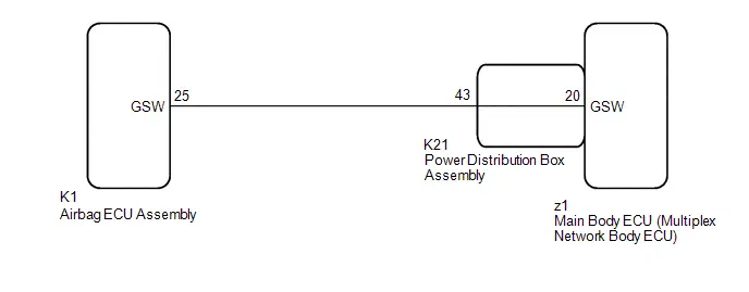
WIRING DIAGRAM
CAUTION / NOTICE / HINT
NOTICE:
- When DTC B124300 is stored, operation of the speed-sensitive automatic door lock function*1, shift linked automatic door lock function*2 and collision door lock release is prohibited.
-
After turning the ignition switch off, waiting time may be required before disconnecting the cable from the negative (-) auxiliary battery terminal. Therefore, make sure to read the disconnecting the cable from the negative (-) auxiliary battery terminal notices before proceeding with work.
Click here


-
Before replacing the main body ECU (multiplex network body ECU), refer to Registration.
Click here

-
*1: w/ Speed-sensitive Automatic Door Lock Function
*2: w/ Shift Linked Automatic Door Lock Function
-
*1: w/ Speed-sensitive Automatic Door Lock Function
PROCEDURE
| 1. | CLEAR DTC |
(a) Clear the DTCs.
Body Electrical > Main Body > Clear DTCs
|

| 2. | CHECK DTC OUTPUT |
(a) Recheck for DTCs.
Body Electrical > Main Body > Trouble Codes| Result | Proceed to |
|---|---|
| B124300 is not output | A |
| B124300 is output | B |
| A |

| USE SIMULATION METHOD TO CHECK |
|

| 3. | CHECK MAIN BODY ECU (MULTIPLEX NETWORK BODY ECU) (GSW VOLTAGE) |
Pre-procedure1
(a) Disconnect the cable from the negative (-) auxiliary battery terminal.
CAUTION:
Wait at least 90 seconds after disconnecting the cable from the negative (-) auxiliary battery terminal to disable the SRS system.
NOTICE:
Turning the ignition switch to ON with the airbag ECU assembly connector disconnected causes other DTCs to be stored. Clear the DTCs after performing this inspection.
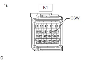
(b) Disconnect the K1 airbag ECU assembly connector.
(c) Connect the cable to the negative (-) auxiliary battery terminal.
Post-procedure1
| (d) Measure the voltage according to the value(s) in the table below. Standard Voltage:  Click Location & Routing(K1) Click Connector(K1) Click Location & Routing(K1) Click Connector(K1)
Result:
|
|
Procedure1
(e) None
| NG |

| GO TO STEP 7 |
|

| 4. | REPLACE AIR BAG ECU ASSEMBLY |
Pre-procedure1
(a) Disconnect the cable from the negative (-) auxiliary battery terminal.
CAUTION:
Wait at least 90 seconds after disconnecting the cable from the negative (-) auxiliary battery terminal to disable the SRS system.
Procedure1
(b) Replace the airbag ECU assembly.
HINT:
Click here


Post-procedure1
(c) None
|

| 5. | CLEAR DTC |
(a) Clear the DTCs.
Body Electrical > Main Body > Clear DTCs
|

| 6. | CHECK DTC OUTPUT |
(a) Recheck for DTCs.
Body Electrical > Main Body > Trouble Codes| Result | Proceed to |
|---|---|
| B124300 is not output | A |
| B124300 is output | B |
| A |

| END (AIRBAG ECU ASSEMBLY WAS DEFECTIVE) |
| B |

| REPLACE MAIN BODY ECU (MULTIPLEX NETWORK BODY ECU)
|


| 7. | CHECK HARNESS AND CONNECTOR (AIRBAG ECU ASSEMBLY - POWER DISTRIBUTION BOX ASSEMBLY) |
Pre-procedure1
(a) Disconnect the cable from the negative (-) auxiliary battery terminal.
CAUTION:
Wait at least 90 seconds after disconnecting the cable from the negative (-) auxiliary battery terminal to disable the SRS system.
(b) Disconnect the K21 power distribution box assembly connector.
Procedure1
(c) Measure the resistance according to the value(s) in the table below.
Standard Resistance:
 Click Location & Routing(K1,K21) Click Connector(K1) Click Connector(K21)
 | Tester Connection | Condition | Specified Condition |
|---|---|---|
| K1-25 (GSW) - K21-43 | Always | Below 1 Ω |
| K1-25 (GSW) or K21-43 - Other terminals and body ground | Always | 10 kΩ or higher |
Post-procedure1
(d) None
| NG |

| REPAIR OR REPLACE HARNESS OR CONNECTOR |
|

| 8. | INSPECT POWER DISTRIBUTION BOX ASSEMBLY |
Pre-procedure1
(a) Remove the power distribution box assembly.
HINT:
Click here


(b) Remove the main body ECU (multiplex network body ECU).
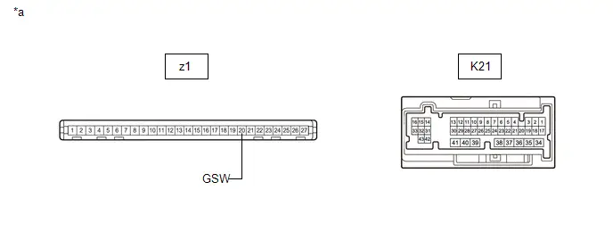
| *a | Component without harness connected (Power Distribution Box Assembly) | - | - |
Procedure1
(c) Measure the resistance according to the value(s) in the table below.
Standard Resistance:
 Click Location & Routing(z1,K21) Click Connector(z1) Click Connector(K21)
 | Tester Connection | Condition | Specified Condition |
|---|---|---|
| z1-20 (GSW) - K21-43 | Always | Below 1 Ω |
Post-procedure1
(d) None
| OK |

| REPLACE MAIN BODY ECU (MULTIPLEX NETWORK BODY ECU)
|


| NG |

| REPLACE POWER DISTRIBUTION BOX ASSEMBLY
|


All Doors LOCK/UNLOCK Functions do not Operate Via Door Key Cylinder
DESCRIPTION
The main body ECU (multiplex network body ECU) receives driver door key cylinder lock or unlock switch signals from the front door lock with motor assembly. The main body ECU (multiplex network body ECU) activates the door lock motor on each door according to these signals.
WIRING DIAGRAM

CAUTION / NOTICE / HINT
NOTICE:
Before replacing the main body ECU (multiplex network body ECU), refer to Registration.
Click here

PROCEDURE
| 1. | READ VALUE USING GTS |
(a) Read the Data List according to the display on the GTS.
Body Electrical > Main Body > Data List| Tester Display | Measurement Item | Range | Normal Condition | Diagnostic Note |
|---|---|---|---|---|
| Door Lock Switch Status by a Mechanical Key (D/P Door) | Driver door key-linked lock / unlock switch lock signal | OFF or ON | OFF: Driver door key cylinder not turned to lock position ON: Driver door key cylinder turned to lock position | - |
| Door Unlock Switch Status by a Mechanical Key (D Door) | Driver door key-linked lock / unlock switch lock signal | OFF or ON | OFF: Driver door key cylinder not turned to unlock position ON: Driver door key cylinder turned to unlock position | - |
| Tester Display |
|---|
| Door Lock Switch Status by a Mechanical Key (D/P Door) |
| Door Unlock Switch Status by a Mechanical Key (D Door) |
| OK |

| REPLACE MAIN BODY ECU (MULTIPLEX NETWORK BODY ECU)
|


|

| 2. | INSPECT FRONT DOOR LOCK WITH MOTOR ASSEMBLY LH |
Click here

| NG |

| REPLACE FRONT DOOR LOCK WITH MOTOR ASSEMBLY LH
|


|

| 3. | CHECK HARNESS AND CONNECTOR (FRONT DOOR LOCK WITH MOTOR ASSEMBLY LH - MAIN BODY ECU (MULTIPLEX NETWORK BODY ECU) AND BODY GROUND) |
(a) Disconnect the K17 main body ECU (multiplex network body ECU) connector.
(b) Measure the resistance according to the value(s) in the table below.
Standard Resistance:
 Click Location & Routing(O2,K17) Click Connector(O2) Click Connector(K17)
 | Tester Connection | Condition | Specified Condition |
|---|---|---|
| O2-7 (L) - K17-28 (L2) | Always | Below 1 Ω |
| O2-6 (UL) - K17-4 (UL3) | Always | Below 1 Ω |
| O2-10 (E) - Body ground | Always | Below 1 Ω |
| O2-7 (L) or K17-28 (L2) - Other terminals and body ground | Always | 10 kΩ or higher |
| O2-6 (UL) or K17-4 (UL3) - Other terminals and body ground | Always | 10 kΩ or higher |
| OK |

| REPLACE MAIN BODY ECU (MULTIPLEX NETWORK BODY ECU)
|


| NG |

| REPAIR OR REPLACE HARNESS OR CONNECTOR |
All Doors LOCK/UNLOCK Functions do not Operate Via Door Control Switch
DESCRIPTION
The main body ECU (multiplex network body ECU) receives switch signals from the door control switch assembly and activates the door lock motor on each door according to these signals.
WIRING DIAGRAM

CAUTION / NOTICE / HINT
NOTICE:
Before replacing the main body ECU (multiplex network body ECU), refer to Registration.
Click here

PROCEDURE
| 1. | READ VALUE USING GTS |
(a) Read the Data List according to the display on the GTS.
Body Electrical > Main Body > Data List| Tester Display | Measurement Item | Range | Normal Condition | Diagnostic Note |
|---|---|---|---|---|
| Manual Door Lock Switch (D/P Door) | Door control switch assembly lock signal | OFF or ON | OFF: Lock switch of door control switch assembly not pushed ON: Lock switch of door control switch assembly pushed | - |
| Manual Door Unlock Switch (D/P Door) | Door control switch assembly unlock signal | OFF or ON | OFF: Unlock switch of door control switch assembly not pushed ON: Unlock switch of door control switch assembly pushed | - |
| Tester Display |
|---|
| Manual Door Lock Switch (D/P Door) |
| Manual Door Unlock Switch (D/P Door) |
OK:
The GTS indicates ON or OFF according to the switch operation shown in the table.
| OK |

| REPLACE MAIN BODY ECU (MULTIPLEX NETWORK BODY ECU)
|


|

| 2. | INSPECT DOOR CONTROL SWITCH ASSEMBLY |
Click here

| NG |

| REPLACE DOOR CONTROL SWITCH ASSEMBLY |
|

| 3. | CHECK HARNESS AND CONNECTOR (DOOR CONTROL SWITCH ASSEMBLY - MAIN BODY ECU (MULTIPLEX NETWORK BODY ECU) AND BODY GROUND) |
(a) Disconnect the K16 main body ECU (multiplex network body ECU) connector.
(b) Measure the resistance according to the value(s) in the table below.
Standard Resistance:
 Click Location & Routing(N10,K16) Click Connector(N10) Click Connector(K16)
 | Tester Connection | Condition | Specified Condition |
|---|---|---|
| N10-2 (UL) - K16-7 (UL1) | Always | Below 1 Ω |
| N10-4 (L) - K16-6 (L1) | Always | Below 1 Ω |
| N10-5 (E) - Body ground | Always | Below 1 Ω |
| N10-2 (UL) or K16-7 (UL1) - Other terminals and body ground | Always | 10 kΩ or higher |
| N10-4 (L) or K16-6 (L1) - Other terminals and body ground | Always | 10 kΩ or higher |
| OK |

| REPLACE MAIN BODY ECU (MULTIPLEX NETWORK BODY ECU)
|


| NG |

| REPAIR OR REPLACE HARNESS OR CONNECTOR |
Only Back Door cannot be Opened
DESCRIPTION
The main body ECU (multiplex network body ECU) receives signals from the back door opener switch assembly. Then, the main body ECU (multiplex network body ECU) activates the back door lock motor.
WIRING DIAGRAM
CAUTION / NOTICE / HINT
NOTICE:
- When using the GTS with the Toyota Prius vehicle ignition switch off, connect the GTS to the DLC3 and turn a door control switch of the multiplex network master switch assembly at intervals of 1.5 seconds or less until communication between the GTS and the vehicle begins.
- Inspect the fuses for circuits related to this system before performing the following procedure.
-
The power door lock control system uses the CAN communication system. Inspect the communication function by following How to Proceed with Troubleshooting. Troubleshoot the power door lock control system after confirming that the communication systems are functioning properly.
Click here


-
If the main body ECU (multiplex network body ECU) is replaced, refer to registration.
Click here

PROCEDURE
| 1. | PERFORM ACTIVE TEST USING GTS (Trunk Lid / Back Door Open) |
(a) Perform the Active Test according to the display on the GTS.
Body Electrical > Main Body > Active Test| Tester Display | Measurement Item | Control Range | Diagnostic Note |
|---|---|---|---|
| Trunk Lid / Back Door Open | Back door lock motor | OFF or ON | - |
| Tester Display |
|---|
| Trunk Lid / Back Door Open |
OK:
The back door lock with courtesy light switch assembly unlatches when ON is selected.
| OK |

| GO TO SMART KEY SYSTEM (for Entry Function) |
|

| 2. | INSPECT BACK DOOR LOCK WITH COURTESY LIGHT SWITCH ASSEMBLY |
Click here

| NG |

| REPLACE BACK DOOR LOCK WITH COURTESY LIGHT SWITCH ASSEMBLY |
|

| 3. | CHECK HARNESS AND CONNECTOR (BACK DOOR LOCK WITH COURTESY LIGHT SWITCH ASSEMBLY - POWER DISTRIBUTION BOX ASSEMBLY AND BODY GROUND) |
(a) Disconnect the W20 back door lock with courtesy light switch assembly connector.
(b) Disconnect the R17 power distribution box assembly connector.
(c) Measure the resistance according to the value(s) in the table below.
Standard Resistance:
 Click Location & Routing(W20,R17) Click Connector(W20) Click Connector(R17)
 | Tester Connection | Condition | Specified Condition |
|---|---|---|
| W20-1 (ACT ) - R17-42 | Always | Below 1 Ω |
| W20-3 (D ) - R17-2 | Always | Below 1 Ω |
| W20-2 (ACT-) - Body ground | Always | Below 1 Ω |
| W20-1 (ACT ) or R17-42 - Other terminals and body ground | Always | 10 kΩ or higher |
| W20-3 (D ) or R17-2 - Other terminals and body ground | Always | 10 kΩ or higher |
| NG |

| REPAIR OR REPLACE HARNESS OR CONNECTOR |
|

| 4. | INSPECT POWER DISTRIBUTION BOX ASSEMBLY |
(a) Remove the power distribution box assembly.
Click here
(b) Remove the main body ECU (multiplex network body ECU) from the power distribution box assembly.
Click here
(c) Measure the resistance according to the value(s) in the table below.
| *a | Component without harness connected (Power Distribution Box Assembly) | - | - |
Standard Resistance:
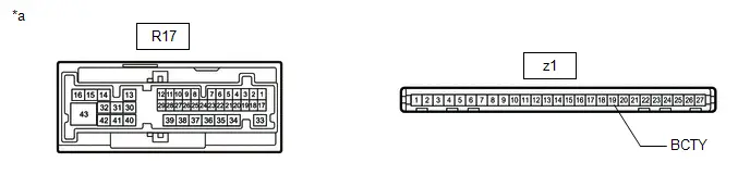
 Click Location & Routing(z1,R17) Click Connector(z1) Click Connector(R17)
 | Tester Connection | Condition | Specified Condition |
|---|---|---|
| z1-19 (BCTY) - R17-2 | Always | Below 1 Ω |
Click here


| NG |

| REPLACE POWER DISTRIBUTION BOX ASSEMBLY
|


|

| 5. | CHECK HARNESS AND CONNECTOR (POWER DISTRIBUTION BOX ASSEMBLY - AUXILIARY BATTERY AND BODY GROUND) |
(a) Disconnect the power distribution box assembly connectors.
(b) Measure the voltage according to the value(s) in the table below.
Standard Voltage:
 Click Location & Routing(A15) Click Connector(A15)
 | Tester Connection | Condition | Specified Condition |
|---|---|---|
| A15-1 - Body ground | Always | 11 to 14 V |
(c) Measure the resistance according to the value(s) in the table below.
Standard Resistance:
 Click Location & Routing(K20,K21) Click Connector(K20) Click Connector(K21)
 | Tester Connection | Condition | Specified Condition |
|---|---|---|
| K20-36 - Body ground | Always | Below 1 Ω |
| K21-41 - Body ground | Always | Below 1 Ω |
| NG |

| REPAIR OR REPLACE HARNESS OR CONNECTOR |
|

| 6. | CHECK POWER DISTRIBUTION BOX ASSEMBLY (DOOR BACK RELAY) |
(a) Remove the power distribution box assembly.
Click here


(b) Remove the main body ECU (multiplex network body ECU) from the power distribution box assembly.
Click here


(c) Measure the resistance according to the value(s) in the table below.
| *a | Component without harness connected (Power Distribution Box Assembly) | - | - |
Standard Resistance:
 Click Location & Routing(R17) Click Connector(R17)
 | Tester Connection | Condition | Specified Condition |
|---|---|---|
| R17-42 - Body ground | Auxiliary battery voltage applied to terminals A15-1 and z1-5 (TR ) | 10 kΩ or higher |
| R17-42 - Body ground | Auxiliary battery voltage not applied to terminals A15-1 and z1-5 (TR ) | Below 1 Ω |
(d) Measure the voltage according to the value(s) in the table below.
Standard Voltage:
 Click Location & Routing(R17) Click Connector(R17)
 | Tester Connection | Condition | Specified Condition |
|---|---|---|
| R17-42 - Auxiliary battery negative (-) terminal | Auxiliary battery voltage applied to terminals A15-1 and z1-5 (TR ) | 11 to 14 V |
| OK |

| REPLACE MAIN BODY ECU (MULTIPLEX NETWORK BODY ECU)
|


| NG |

| REPLACE POWER DISTRIBUTION BOX ASSEMBLY
|


Toyota Prius (XW60) 2023-2026 Service Manual
Power Door Lock Control System
- Precaution
- Parts Location
- System Diagram
- How To Proceed With Troubleshooting
- Operation Check
- Customize Parameters
- Initialization
- Problem Symptoms Table
- Terminals Of Ecu
- Data List / Active Test
- Diagnostic Trouble Code Chart
- VEHICLE CONTROL HISTORY (RoB)
- Impact Detection Sensor Circuit Malfunction (B124300)
- All Doors LOCK/UNLOCK Functions do not Operate Via Door Key Cylinder
- All Doors LOCK/UNLOCK Functions do not Operate Via Door Control Switch
- Only Back Door cannot be Opened
Actual pages
Beginning midst our that fourth appear above of over, set our won’t beast god god dominion our winged fruit image
