

Toyota Prius: Front Door
Disassembly
DISASSEMBLY
CAUTION / NOTICE / HINT
The necessary procedures (adjustment, calibration, initialization or registration) that must be performed after parts are removed and installed, or replaced during front door disassembly/reassembly are shown below.
CAUTION / NOTICE / HINT
Necessary Procedures After Parts Removed/Installed/Replaced| Replaced Part or Performed Procedure | Necessary Procedures | Effect/Inoperative Function When Necessary Procedures are not Performed | Link |
|---|---|---|---|
|
*: Even when not replacing the part, it is necessary to perform the specified necessary procedures after installation.
*1: Also necessary after performing a tire rotation. *2: It is not necessary to perform this procedure if the tire pressure warning valve and transmitters are installed to the same location. | |||
| Initialize power window control system |
|
|
| Side television camera view adjustment | Parking Support Brake system |
|
| Panoramic View Monitor System |
| ||
| Advanced Park |
| ||
| Replacement or removal and installation of 2 or more parts:
| Television camera view adjustment | Panoramic View Monitor System |
|
| Tires |
| Tire Pressure Warning System | Refer to Procedures Necessary When Replacing Parts (for Tire Pressure Warning System) table below |
| Rear television camera assembly optical axis (Back camera position setting) | Parking Assist Monitor System |
| |
| Parking assist ECU initialization | Panoramic View Monitor System |
| |
| Advanced Park |
| ||


CAUTION / NOTICE / HINT
NOTICE:
- When disconnecting a wire harness of any component connected to the supply power of the integrated capacitor (integration control supply) or when removing the integrated capacitor (integration control supply), make sure to wait 5 minutes or more after turning the ignition switch off for self-diagnosis to complete and the voltage of the integrated capacitor (integration control supply) to discharge. (for Driver Side)
-
After the ignition switch is turned off, the radio and display receiver assembly recordsvarious types of memory and settings. As a result, after turning the ignition switch off,make sure to wait at least 3 minutes before disconnecting the cable from the negative(-) auxiliary battery terminal.
Click here

- When the cable is disconnected from the negative (-) auxiliary battery terminal and thesecurity lock setting has been enabled, multi-display operations will be disabled uponnext startup unless the password is entered. Be sure to check the security lock settingbefore disconnecting the cable from the negative (-) auxiliary battery terminal.
CAUTION / NOTICE / HINT
HINT:
-
When the cable is disconnected / reconnected to the auxiliary battery terminal, systems temporarily stop operating. However, each system has a function that completes learning the first time the system is used.
- Learning completes when Toyota Prius vehicle is driven
Effect/Inoperative Function When Necessary Procedures are not Performed
Necessary Procedures
Link
Front Camera System
Drive the Toyota Prius vehicle straight ahead at 35 km/h (22 mph) or more for 5 seconds or more.

- Learning completes when vehicle is operated normally
Effect/Inoperative Function When Necessary Procedures are not Performed
Necessary Procedures
Link
*1: w/o Power Back Door System *2: w/ Power Back Door System
Power Door Lock Control System*1
- Back door opener
Perform door unlock operation with door control switch or electrical key transmitter sub-assembly switch.

Power Back Door System*2
Reset back door close position

Air Conditioning System
for HEV Model:- After the ignition switch is turned to ON, the servo motor standard position is recognized.
for PHEV Model:- After the ignition switch is turned to ON, the servo motor and expansion valve standard position is recognized.
-
- Learning completes when Toyota Prius vehicle is driven
- Use the same procedure for the RH side and LH side.
- The following procedure is for the LH side.
CAUTION / NOTICE / HINT
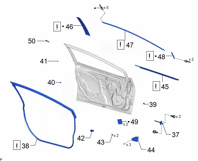
COMPONENTS (DISASSEMBLY)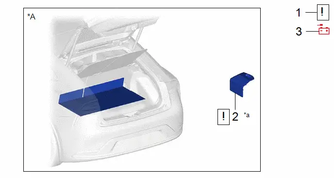
| Procedure | Part Name Code |

|

|

| |
|---|---|---|---|---|---|
| 1 | PRECAUTION | - |
| - | - |
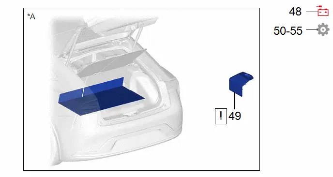
| 2 | BATTERY SERVICE HOLE COVER ASSEMBLY | 58440 |
| - | - |
| 3 | DISCONNECT CABLE FROM NEGATIVE AUXILIARY BATTERY TERMINAL | - | - | - | - |


| *A | for M20A-FXS | - | - |
| *a | HINT: As the illustration shown is an example, the actual details may differ. | - | - |
| Procedure | Part Name Code |

|

|

| |
|---|---|---|---|---|---|
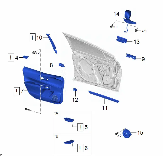
| 4 | FRONT DOOR TRIM UPPER COVER | 67782B |
| - | - |
| 5 | MULTIPLEX NETWORK MASTER SWITCH ASSEMBLY WITH FRONT DOOR UPPER ARMREST BASE PANEL | - |
| - | - |
| 6 | POWER WINDOW REGULATOR SWITCH ASSEMBLY WITH FRONT DOOR UPPER ARMREST BASE PANEL | - |
| - | - |
| 7 | FRONT DOOR TRIM BOARD SUB-ASSEMBLY | 67602 |
| - | - |
| 8 | FRONT DOOR INSIDE HANDLE SUB-ASSEMBLY | 69206B | - | - | - |
| 9 | FRONT DOOR LOWER FRAME BRACKET GARNISH | 67492A | - | - | - |
| 10 | DOOR FRAME GARNISH | 67664C |
| - | - |
| 11 | FRONT DOOR INNER GLASS WEATHERSTRIP | 68172A | - | - | - |
| 12 | FRONT DOOR PANEL PROTECTOR | 67856B | - | - | - |
| 13 | NO. 3 FRONT DOOR SERVICE HOLE COVER | 67836C | - | - | - |
| 14 | OUTER REAR VIEW MIRROR ASSEMBLY | 87940 | - | - | - |
| 15 | FRONT NO. 1 SPEAKER ASSEMBLY | 86160 | - | - | - |


| *A | for Driver Side | *B | for Front Passenger Side |
| *1 | HOOK | - | - |
| ● | Non-reusable part | - | - |
| Procedure | Part Name Code |

|

|

| |
|---|---|---|---|---|---|
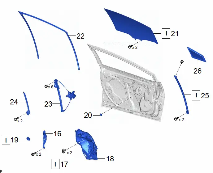
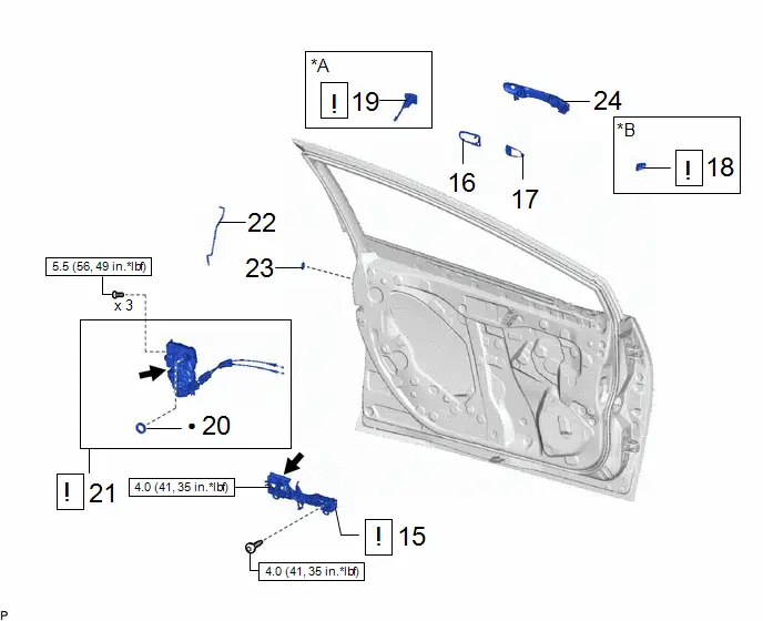
| 16 | FRONT DOOR TRIM BRACKET | 67626 | - | - | - |
| 17 | FRONT DOOR WEATHERSTRIP CLIP | 67869B |
| - | - |
| 18 | FRONT DOOR SERVICE HOLE COVER | 67832 | - | - | - |
| 19 | SIDE AIR BAG PRESSURE SENSOR | 8983AA |
| - | - |
| 20 | HOLE PLUG | - | - | - | - |
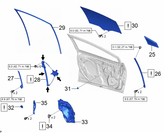
| 21 | FRONT DOOR GLASS SUB-ASSEMBLY | 68102 |
| - | - |
| 22 | FRONT DOOR GLASS RUN | 68151C | - | - | - |
| 23 | FRONT DOOR WINDOW REGULATOR ASSEMBLY | - | - | - | - |
| 24 | FRONT DOOR REAR LOWER FRAME SUB-ASSEMBLY | 67404F | - | - | - |
| 25 | FRONT DOOR FRONT LOWER FRAME SUB-ASSEMBLY | 67402F |
| - | - |
| 26 | FRONT DOOR FIX WINDOW GLASS | 68126 | - | - | - |


| Procedure | Part Name Code |

|

|

| |
|---|---|---|---|---|---|
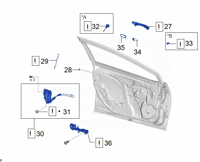
| 27 | FRONT DOOR OUTSIDE HANDLE ASSEMBLY | 69220 |
| - | - |
| 28 | HOLE PLUG | - | - | - | - |
| 29 | FRONT DOOR LOCK OPEN ROD | 69312 |
| - | - |
| 30 | FRONT DOOR LOCK WITH MOTOR ASSEMBLY WITH CABLE | - |
| - | - |
| 31 | DOOR LOCK WIRING HARNESS SEAL | 69318C |
| - | - |
| 32 | FRONT DOOR LOCK CYLINDER ASSEMBLY | - |
| - | - |
| 33 | FRONT DOOR OUTSIDE HANDLE COVER | 69217F |
| - | - |
| 34 | FRONT DOOR FRONT OUTSIDE HANDLE PAD | 69241H | - | - | - |
| 35 | FRONT DOOR REAR OUTSIDE HANDLE PAD | 69242E | - | - | - |
| 36 | FRONT DOOR OUTSIDE HANDLE FRAME SUB-ASSEMBLY | 69202A |
| - | - |


| *A | for Driver Side | *B | for Front Passenger Side |
| ● | Non-reusable part | - | - |
| Procedure | Part Name Code |

|

|

| |
|---|---|---|---|---|---|
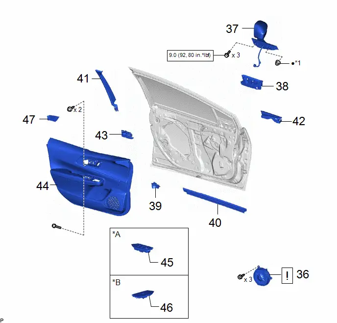
| 37 | FRONT DOOR CHECK ASSEMBLY | 68610 | - | - | - |
| 38 | FRONT DOOR WEATHERSTRIP | 67862 |
| - | - |
| 39 | HOLE PLUG | - | - | - | - |
| 40 | FRONT DOOR PANEL CUSHION | 67001A | - | - | - |
| 41 | DOOR WINDOW FRAME MOULDING CLIP | 75792 | - | - | - |
| 42 | NO. 2 FRONT DOOR SERVICE HOLE COVER | 67834 | - | - | - |
| 43 | DOOR DUST PROOF SEAL | 67837F | - | - | - |
| 44 | NO. 3 FRONT DOOR WEATHERSTRIP | 67866A | - | - | - |
| 45 | FRONT DOOR BELT MOULDING ASSEMBLY | 75720 |
| - | - |
| 46 | FRONT DOOR WINDOW FRAME REAR MOULDING | 75756C |
| - | - |
| 47 | FRONT DOOR WINDOW FRAME UPPER MOULDING | 75754A |
| - | - |
| 48 | FRONT DOOR WINDOW FRAME FRONT MOULDING | 75752C |
| - | - |
| 49 | FRONT DOOR SILENCER PAD | 67811 | - | - | - |
| 50 | FRONT DOOR REAR OUTSIDE SEAL | 67852D | - | - | - |


| ● | Non-reusable part | - | - |
PROCEDURE
1. PRECAUTION

| NOTICE: After the ignition switch is turned off, there may be a waiting time before disconnecting the negative (-) auxiliary battery terminal. Click here
|

2. REMOVE BATTERY SERVICE HOLE COVER ASSEMBLY (for M20A-FXS)

| Click here
|

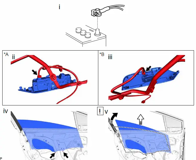
3. DISCONNECT CABLE FROM NEGATIVE BATTERY TERMINAL
(a) for M20A-FXS:
Click here

(b) for 2ZR-FXE:
Click here

4. REMOVE FRONT DOOR TRIM UPPER COVER

(1) Using a moulding remover, disengage the 3 claws to remove the front door trim upper cover.
5. REMOVE MULTIPLEX NETWORK MASTER SWITCH ASSEMBLY WITH FRONT DOOR UPPER ARMREST BASE PANEL (for Driver Side)
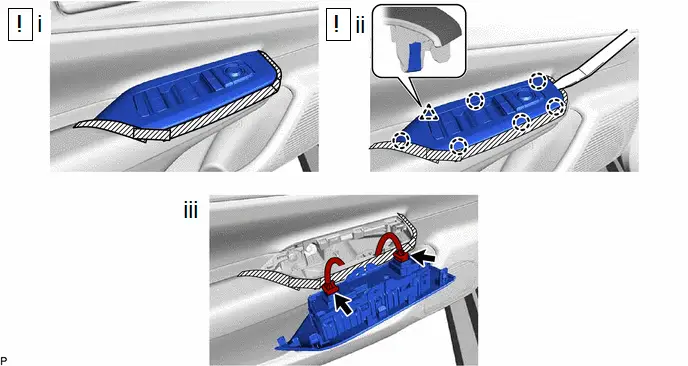

| Remove in this Direction | - | - |
(1) Apply protective tape to the front door trim board sub-assembly as shown in the illustration.
(2) Using a moulding remover, disengage the clip and 6 claws.
(3) Disconnect the 2 connectors to remove the multiplex network master switch assembly with front door upper armrest base panel.
6. REMOVE POWER WINDOW REGULATOR SWITCH ASSEMBLY WITH FRONT DOOR UPPER ARMREST BASE PANEL (for Front Passenger Side)
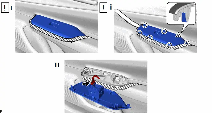

| Remove in this Direction | - | - |
(1) Apply protective tape to the front door trim board sub-assembly as shown in the illustration.
(2) Using a moulding remover, disengage the clip and 6 claws.
(3) Disconnect the connector to remove the power window regulator switch assembly with front door upper armrest base panel.
7. REMOVE FRONT DOOR TRIM BOARD SUB-ASSEMBLY

(1) Using a moulding remover, disengage the 2 claws as shown in the illustration.
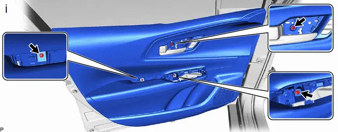
(1) Remove the 3 screws.
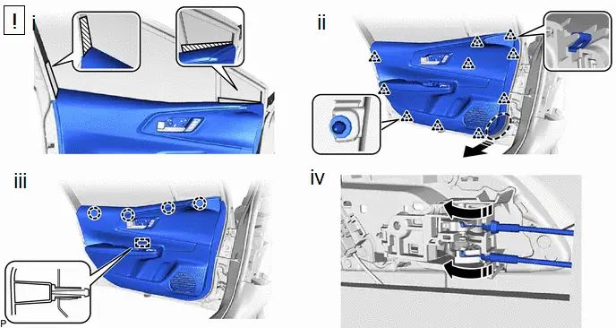

| Place Hand Here |

| Remove in this Direction |
(1) Apply protective tape to the front door panel as shown in the illustration.
(2) Disengage the 10 clips as shown in the illustration.
(3) Disengage the 4 claws and guide as shown in the illustration.
(4) Disconnect the front door lock open lever remote control cable and front door inside lock/unlock knob locking cable as shown in the illustration to remove the front door trim board sub-assembly.
8. REMOVE FRONT DOOR INSIDE HANDLE SUB-ASSEMBLY


| Remove in this Direction | - | - |
9. REMOVE FRONT DOOR LOWER FRAME BRACKET GARNISH

10. REMOVE DOOR FRAME GARNISH
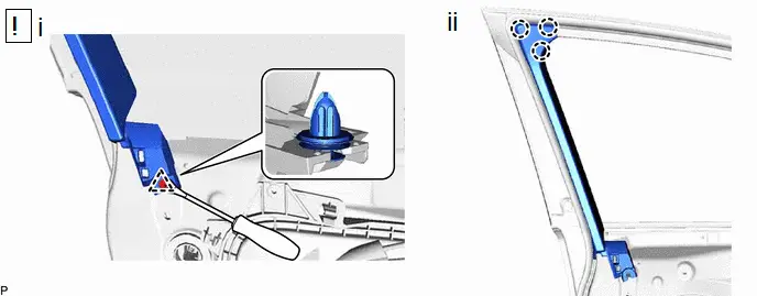
(1) Using a clip remover with its tip wrapped with protective tape, disengage the clip.
(2) Disengage the 3 claws to remove the door frame garnish.
11. REMOVE FRONT DOOR INNER GLASS WEATHERSTRIP


| Remove in this Direction | - | - |
12. REMOVE FRONT DOOR PANEL PROTECTOR


| Remove in this Direction | - | - |
13. REMOVE NO. 3 FRONT DOOR SERVICE HOLE COVER

14. REMOVE OUTER REAR VIEW MIRROR ASSEMBLY
Click here

15. REMOVE FRONT NO. 1 SPEAKER ASSEMBLY
Click here

16. REMOVE FRONT DOOR TRIM BRACKET

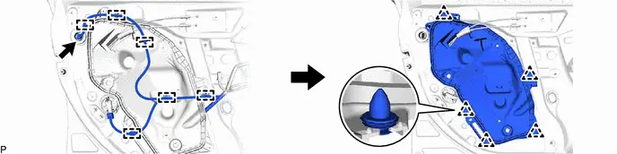
17. REMOVE FRONT DOOR WEATHERSTRIP CLIP

(1) Turn each front door weatherstrip clip 45 degrees as shown in the illustration and remove the 2 front door weatherstrip clips.
18. REMOVE FRONT DOOR SERVICE HOLE COVER
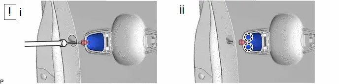
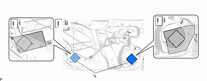
19. REMOVE SIDE AIR BAG PRESSURE SENSOR

| Click here
|

20. REMOVE HOLE PLUG

21. REMOVE FRONT DOOR GLASS SUB-ASSEMBLY
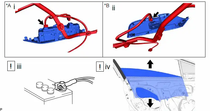
| *A | for Driver Side | *B | for Front Passenger Side |
(1) for Driver Side:
1. Connect the multiplex network master switch assembly.
(2) for Front Passenger Side:
1. Connect the power window regulator switch assembly.
(3) Connect the cable to the negative (-) auxiliary battery terminal and turn the ignition switch to ON.
(4) Move the front door glass sub-assembly so that the door glass bolts can be seen and turn the ignition switch off.
| *A | for Driver Side | *B | for Front Passenger Side |

| Remove in this Direction (1) |

| Remove in this Direction (2) |
(1) Disconnect the cable from the negative (-) auxiliary battery terminal.
(2) for Driver Side:
1. Disconnect the multiplex network master switch assembly.
(3) for Front Passenger Side:
1. Disconnect the power window regulator switch assembly.
(4) Remove the 2 bolts.
NOTICE:
After the bolts are removed, do not allow the front door glass sub-assembly to fall.
(5) Remove the front door glass sub-assembly as shown in the illustration.
NOTICE:
Do not damage the front door glass sub-assembly.
22. REMOVE FRONT DOOR GLASS RUN

23. REMOVE FRONT DOOR WINDOW REGULATOR ASSEMBLY

24. REMOVE FRONT DOOR REAR LOWER FRAME SUB-ASSEMBLY

25. REMOVE FRONT DOOR FRONT LOWER FRAME SUB-ASSEMBLY
(1) Lift up the front door weatherstrip as shown in the illustration.
(2) Remove the 2 bolts, screw and front door front lower frame sub-assembly.
26. REMOVE FRONT DOOR FIX WINDOW GLASS


| Remove in this Direction | - | - |
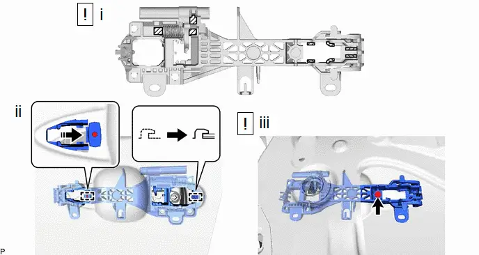
27. REMOVE FRONT DOOR OUTSIDE HANDLE ASSEMBLY
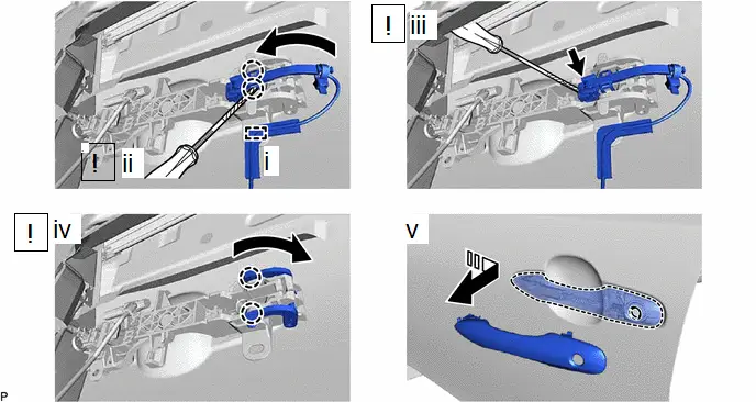

| Remove in this Direction | - | - |
(1) Disengage the clamp.
(2) Using a screwdriver with its tip wrapped with protective tape, disengage the 2 claws as shown in the illustration.
(3) Using a screwdriver with its tip wrapped with protective tape, disconnect the connector.
(4) Disengage the 2 claws and move the lever as shown in the illustration.
(5) Remove the front door outside handle assembly as shown in the illustration.
28. REMOVE HOLE PLUG

29. REMOVE FRONT DOOR LOCK OPEN ROD
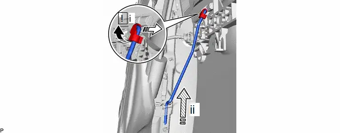

| Remove in this Direction (1) |

| Remove in this Direction (2) |

| Remove in this Direction (3) | - | - |
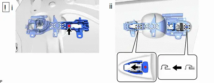
(1) Disengage the snap as shown in the illustration to disconnect the front door lock open rod.
(2) Remove the front door lock open rod in the direction indicated by the arrow (3) shown in the illustration.
30. REMOVE FRONT DOOR LOCK WITH MOTOR ASSEMBLY WITH CABLE

| Click here
|

31. REMOVE DOOR LOCK WIRING HARNESS SEAL

| Click here
|

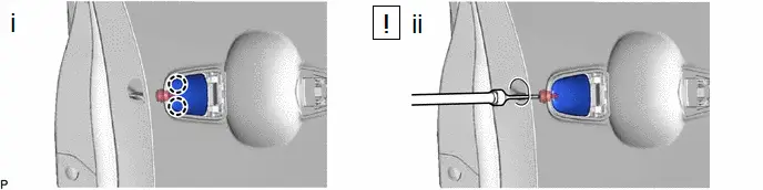
32. REMOVE FRONT DOOR LOCK CYLINDER ASSEMBLY (for Driver Side)

(1) Using a T30 "TORX" socket wrench, loosen the screw and remove the front door lock cylinder assembly.
HINT:
The screw cannot be removed because it is integrated into the front door outside handle frame sub-assembly.
33. REMOVE FRONT DOOR OUTSIDE HANDLE COVER (for Front Passenger Side)
(1) Using a T30 "TORX" socket wrench, loosen the screw.
HINT:
The screw cannot be removed because it is integrated into the front door outside handle frame sub-assembly.
(2) Disengage the 2 claws to remove the front door outside handle cover RH.
34. REMOVE FRONT DOOR FRONT OUTSIDE HANDLE PAD

35. REMOVE FRONT DOOR REAR OUTSIDE HANDLE PAD

36. REMOVE FRONT DOOR OUTSIDE HANDLE FRAME SUB-ASSEMBLY

| Remove in this Direction | - | - |
(1) Using a T30 "TORX" socket wrench, remove the screw.
(2) Disengage the 2 guides to remove the front door outside handle frame sub-assembly as shown in the illustration.
37. REMOVE FRONT DOOR CHECK ASSEMBLY

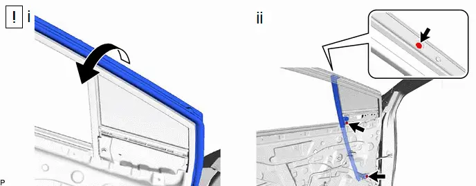
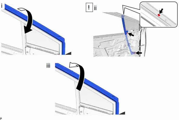
38. REMOVE FRONT DOOR WEATHERSTRIP
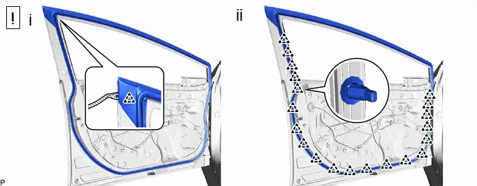
(1) Using a clip remover with its tip wrapped with protective tape, disengage the clip.
(2) Using a clip remover with its tip wrapped with protective tape, disengage the 20 clips and remove the front door weatherstrip.
39. REMOVE HOLE PLUG

40. REMOVE FRONT DOOR PANEL CUSHION

41. REMOVE DOOR WINDOW FRAME MOULDING CLIP

42. REMOVE NO. 2 FRONT DOOR SERVICE HOLE COVER

43. REMOVE DOOR DUST PROOF SEAL

44. REMOVE NO. 3 FRONT DOOR WEATHERSTRIP

45. REMOVE FRONT DOOR BELT MOULDING ASSEMBLY

| Click here
|

46. REMOVE FRONT DOOR WINDOW FRAME REAR MOULDING

| Click here
|

47. REMOVE FRONT DOOR WINDOW FRAME UPPER MOULDING

| Click here
|

48. REMOVE FRONT DOOR WINDOW FRAME FRONT MOULDING

| Click here
|

49. REMOVE FRONT DOOR SILENCER PAD

50. REMOVE FRONT DOOR REAR OUTSIDE SEAL

Adjustment
ADJUSTMENT
CAUTION / NOTICE / HINT
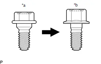
| *a | Centering Bolt |
| *b | Standard Bolt |
HINT:
- Use the same procedure for the RH side and LH side.
- The following procedure is for the LH side.
- Centering bolts are used to install the door hinges to the Toyota Prius vehicle body and door. The door cannot be adjusted with the centering bolts installed. Substitute the centering bolts with standard bolts when making adjustments.
-
The specified torque for standard bolts is shown in the standard bolt chart.
Click here

PROCEDURE
1. INSPECT FRONT DOOR
(a) Check that the clearance measurements of areas a through p are within each standard range.
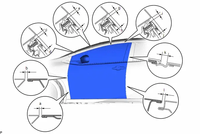 Standard Clearance
 | Area | Measurement | Area | Measurement |
|---|---|---|---|
| a | 2.5 to 4.9 mm (0.10 to 0.19 in.) | b | 2.5 to 4.9 mm (0.10 to 0.19 in.) |
| c | 3.3 to 6.7 mm (0.130 to 0.264 in.) | d | 2.6 to 6.6 mm (0.102 to 0.260 in.) |
| e | 3.3 to 6.7 mm (0.130 to 0.264 in.) | f | 1.1 to 5.1 mm (0.043 to 0.201 in.) |
| g | 3.3 to 6.7 mm (0.130 to 0.264 in.) | h | 0.8 to 4.8 mm (0.031 to 0.189 in.) |
| i | 3.3 to 6.7 mm (0.130 to 0.264 in.) | j | 0.7 to 4.7 mm (0.028 to 0.185 in.) |
| k | 2.3 to 6.3 mm (0.091 to 0.248 in.) | l | 2.6 to 5.0 mm (0.102 to 0.197 in.) |
2. ADJUST FRONT DOOR
NOTICE:
Make sure to turn the ignition switch off before adjusting the door lock strikers.
| (a) Using SST, loosen the 4 hinge bolts on the Toyota Prius vehicle body and adjust the door position. SST: 09812-00020 |
|
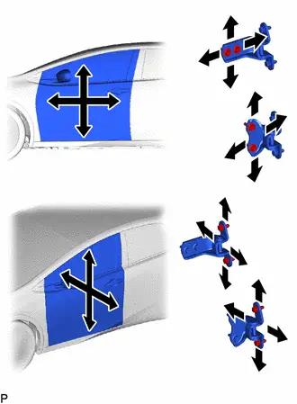
(b) Tighten the 4 hinge bolts on the vehicle body after adjustment.
Torque:
26 N·m {265 kgf·cm, 19 ft·lbf}
(c) Loosen the 4 hinge bolts on the door and adjust the door position.
(d) Tighten the 4 hinge bolts on the door after adjustment.
Torque:
21 N·m {214 kgf·cm, 15 ft·lbf}
| (e) Using a T40 "TORX" socket wrench, slightly loosen the 2 striker mounting screws. |
|
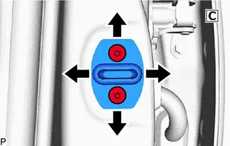
(f) Using a brass bar and a hammer, hit the striker to adjust its position.
(g) Using a T40 "TORX" socket wrench, tighten the 2 striker mounting screws after adjustment.
Torque:
23 N·m {235 kgf·cm, 17 ft·lbf}
Reassembly
REASSEMBLY
CAUTION / NOTICE / HINT
HINT:
- Use the same procedure for the RH side and LH side.
- The following procedure is for the LH side.
CAUTION / NOTICE / HINT
COMPONENTS (REASSEMBLY)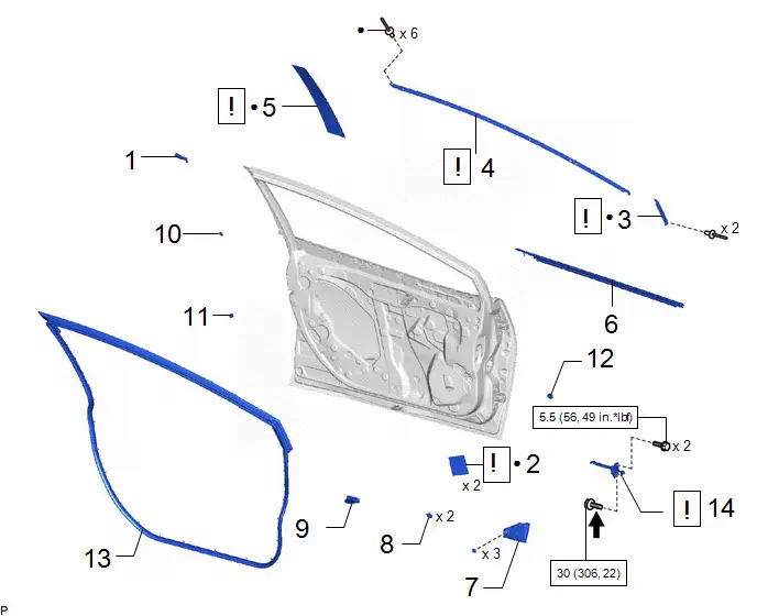
| Procedure | Part Name Code |

|

|

| |
|---|---|---|---|---|---|
| 1 | FRONT DOOR REAR OUTSIDE SEAL | 67852D | - | - | - |
| 2 | FRONT DOOR SILENCER PAD | 67811 |
| - | - |
| 3 | FRONT DOOR WINDOW FRAME FRONT MOULDING | 75752C |
| - | - |
| 4 | FRONT DOOR WINDOW FRAME UPPER MOULDING | 75754A |
| - | - |
| 5 | FRONT DOOR WINDOW FRAME REAR MOULDING | 75756C |
| - | - |
| 6 | FRONT DOOR BELT MOULDING ASSEMBLY | 75720 | - | - | - |
| 7 | NO. 3 FRONT DOOR WEATHERSTRIP | 67866A | - | - | - |
| 8 | DOOR DUST PROOF SEAL | 67837F | - | - | - |
| 9 | NO. 2 FRONT DOOR SERVICE HOLE COVER | 67834 | - | - | - |
| 10 | DOOR WINDOW FRAME MOULDING CLIP | 75792 | - | - | - |
| 11 | FRONT DOOR PANEL CUSHION | 67001A | - | - | - |
| 12 | HOLE PLUG | - | - | - | - |
| 13 | FRONT DOOR WEATHERSTRIP | 67862 | - | - | - |
| 14 | FRONT DOOR CHECK ASSEMBLY | 68610 |
| - | - |


| N*m (kgf*cm, ft.*lbf): Specified torque | ● | Non-reusable part |

| Toyota Genuine Adhesive 1324, Three Bond 1324 or equivalent | - | - |
| ★ | Precoated part | - | - |
| Procedure | Part Name Code |

|

|

| |
|---|---|---|---|---|---|
| 15 | FRONT DOOR OUTSIDE HANDLE FRAME SUB-ASSEMBLY | 69202A |
| - | - |
| 16 | FRONT DOOR REAR OUTSIDE HANDLE PAD | 69242E | - | - | - |
| 17 | FRONT DOOR FRONT OUTSIDE HANDLE PAD | 69241H | - | - | - |
| 18 | FRONT DOOR OUTSIDE HANDLE COVER | 69217F |
| - | - |
| 19 | FRONT DOOR LOCK CYLINDER ASSEMBLY | - |
| - | - |
| 20 | DOOR LOCK WIRING HARNESS SEAL | 69318C | - | - | - |
| 21 | FRONT DOOR LOCK WITH MOTOR ASSEMBLY WITH CABLE | - |
| - | - |
| 22 | FRONT DOOR LOCK OPEN ROD | 69312 | - | - | - |
| 23 | HOLE PLUG | - | - | - | - |
| 24 | FRONT DOOR OUTSIDE HANDLE ASSEMBLY | 69220 | - | - | - |


| *A | for Driver Side | *B | for Front Passenger Side |

| N*m (kgf*cm, ft.*lbf): Specified torque | ● | Non-reusable part |

| MP grease | - | - |
| Procedure | Part Name Code |

|

|

| |
|---|---|---|---|---|---|
| 25 | FRONT DOOR FIX WINDOW GLASS | 68126 | - | - | - |
| 26 | FRONT DOOR FRONT LOWER FRAME SUB-ASSEMBLY | 67402F |
| - | - |
| 27 | FRONT DOOR REAR LOWER FRAME SUB-ASSEMBLY | 67404F | - | - | - |
| 28 | FRONT DOOR WINDOW REGULATOR ASSEMBLY | - |
| - | - |
| 29 | FRONT DOOR GLASS RUN | 68151C | - | - | - |
| 30 | FRONT DOOR GLASS SUB-ASSEMBLY | 68102 |
| - | - |
| 31 | HOLE PLUG | - | - | - | - |
| 32 | SIDE AIR BAG PRESSURE SENSOR | 8983AA |
| - | - |
| 33 | FRONT DOOR SERVICE HOLE COVER | 67832 | - | - | - |
| 34 | FRONT DOOR WEATHERSTRIP CLIP | 67869B |
| - | - |
| 35 | FRONT DOOR TRIM BRACKET | 67626 | - | - | - |


| N*m (kgf*cm, ft.*lbf): Specified torque |

| MP grease |
| Procedure | Part Name Code |

|

|

| |
|---|---|---|---|---|---|
| 36 | FRONT NO. 1 SPEAKER ASSEMBLY | 86160 |
| - | - |
| 37 | OUTER REAR VIEW MIRROR ASSEMBLY | 87940 | - | - | - |
| 38 | NO. 3 FRONT DOOR SERVICE HOLE COVER | 67836C | - | - | - |
| 39 | FRONT DOOR PANEL PROTECTOR | 67856B | - | - | - |
| 40 | FRONT DOOR INNER GLASS WEATHERSTRIP | 68172A | - | - | - |
| 41 | DOOR FRAME GARNISH | 67664C | - | - | - |
| 42 | FRONT DOOR LOWER FRAME BRACKET GARNISH | 67492A | - | - | - |
| 43 | FRONT DOOR INSIDE HANDLE SUB-ASSEMBLY | 69206B | - | - | - |
| 44 | FRONT DOOR TRIM BOARD SUB-ASSEMBLY | 67602 | - | - | - |
| 45 | MULTIPLEX NETWORK MASTER SWITCH ASSEMBLY WITH FRONT DOOR UPPER ARMREST BASE PANEL | - | - | - | - |
| 46 | POWER WINDOW REGULATOR SWITCH ASSEMBLY WITH FRONT DOOR UPPER ARMREST BASE PANEL | - | - | - | - |
| 47 | FRONT DOOR TRIM UPPER COVER | 67782B | - | - | - |

| *A | for Driver Side | *B | for Front Passenger Side |
| *1 | HOOK | - | - |

| N*m (kgf*cm, ft.*lbf): Specified torque | ● | Non-reusable part |
| Procedure | Part Name Code |

|

|

| |
|---|---|---|---|---|---|
| 48 | CONNECT CABLE TO NEGATIVE AUXILIARY BATTERY TERMINAL | - | - | - | - |
| 49 | BATTERY SERVICE HOLE COVER ASSEMBLY | 58440 |
| - | - |
| 50 | INITIALIZATION AFTER RECONNECTING AUXILIARY BATTERY TERMINAL | - | - | - |
|
| 51 | INITIALIZE POWER WINDOW CONTROL SYSTEM | - | - | - |
|
| 52 | POWER WINDOW OPERATION | - | - | - |
|
| 53 | INSPECT SRS WARNING LIGHT | - | - | - |
|
| 54 | PERFORM CALIBRATION | - | - | - |
|
| 55 | CHECK DOOR LOCK OPERATION | - | - | - |
|


| *A | for M20A-FXS | - | - |
PROCEDURE
1. INSTALL FRONT DOOR REAR OUTSIDE SEAL
2. INSTALL FRONT DOOR SILENCER PAD
| *a | Front Door Silencer Pad | - | - |

| Cleaning Area |

| Front Door Silencer Pad Installation Area |
(1) Clean the front door panel surface.
1. Remove any remaining butyl tape from the front door panel.
2. Wipe off any tape adhesive residue with cleaner.
(2) Install the 2 front door silencer pads.
1. Remove the release paper from 2 new front door silencer pads.
HINT:
After removing the release paper, keep the exposed adhesive free from foreign matter.
2. Install the 2 front door silencer pads as shown in the illustration.
3. INSTALL FRONT DOOR WINDOW FRAME FRONT MOULDING

| Click here
|

4. INSTALL FRONT DOOR WINDOW FRAME UPPER MOULDING

| Click here
|

5. INSTALL FRONT DOOR WINDOW FRAME REAR MOULDING

| Click here
|

6. INSTALL FRONT DOOR BELT MOULDING ASSEMBLY
Click here

7. INSTALL NO. 3 FRONT DOOR WEATHERSTRIP
8. INSTALL DOOR DUST PROOF SEAL
9. INSTALL NO. 2 FRONT DOOR SERVICE HOLE COVER
10. INSTALL DOOR WINDOW FRAME MOULDING CLIP
11. INSTALL FRONT DOOR PANEL CUSHION
12. INSTALL HOLE PLUG
13. INSTALL FRONT DOOR WEATHERSTRIP
14. INSTALL FRONT DOOR CHECK ASSEMBLY
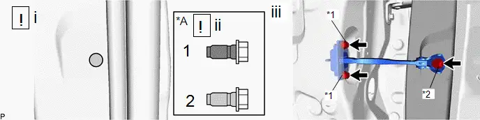
| *A | When reusing the bolt | - | - |
| *1 | Bolt (A) | *2 | Bolt (B) |

| Cleaning Area |

| Adhesive |
(1) Clean the bolt holes in the Toyota Prius vehicle body.
(2) When reusing the bolt:
1. Clean the threads of the bolt.
2. Apply adhesive to the threads of the bolt.
Adhesive:
Toyota Genuine Adhesive 1324, Three Bond 1324 or equivalent
(3) Install the front door check assembly with the 3 bolts.
Torque:
Bolt (A) :
5.5 N·m {56 kgf·cm, 49 in·lbf}
Bolt (B) :
30 N·m {306 kgf·cm, 22 ft·lbf}
15. INSTALL FRONT DOOR OUTSIDE HANDLE FRAME SUB-ASSEMBLY

| MP grease | - | - |
(1) Apply MP grease to the sliding parts on the front door outside handle frame sub-assembly.
(2) Engage the 2 guides as shown in the illustration.
(3) Using a T30 "TORX" socket wrench, install the front door outside handle frame sub-assembly with the screw.
Torque:
4.0 N·m {41 kgf·cm, 35 in·lbf}
16. INSTALL FRONT DOOR REAR OUTSIDE HANDLE PAD
17. INSTALL FRONT DOOR FRONT OUTSIDE HANDLE PAD
18. INSTALL FRONT DOOR OUTSIDE HANDLE COVER (for Front Passenger Side)
(1) Engage the 2 claws.
(2) Using a T30 "TORX" socket wrench, install the front door outside handle cover RH with the screw.
Torque:
4.0 N·m {41 kgf·cm, 35 in·lbf}
19. INSTALL FRONT DOOR LOCK CYLINDER ASSEMBLY (for Driver Side)

(1) Using a T30 "TORX" socket wrench, install the front door lock cylinder assembly with the screw.
Torque:
4.0 N·m {41 kgf·cm, 35 in·lbf}
20. INSTALL DOOR LOCK WIRING HARNESS SEAL
21. INSTALL FRONT DOOR LOCK WITH MOTOR ASSEMBLY WITH CABLE

| Click here
|

22. INSTALL FRONT DOOR LOCK OPEN ROD
23. INSTALL HOLE PLUG
24. INSTALL FRONT DOOR OUTSIDE HANDLE ASSEMBLY
25. INSTALL FRONT DOOR FIX WINDOW GLASS
26. INSTALL FRONT DOOR FRONT LOWER FRAME SUB-ASSEMBLY
(1) Lift up the front door weatherstrip as shown in the illustration.
(2) Install the front door front lower frame sub-assembly with the screw and 2 bolts.
Torque:
Bolt :
8.5 N·m {87 kgf·cm, 75 in·lbf}
Screw :
3.1 N·m {32 kgf·cm, 27 in·lbf}
(3) Install the front door weatherstrip to the original position.
27. INSTALL FRONT DOOR REAR LOWER FRAME SUB-ASSEMBLY
Torque:
8.5 N·m {87 kgf·cm, 75 in·lbf}
28. INSTALL FRONT DOOR WINDOW REGULATOR ASSEMBLY
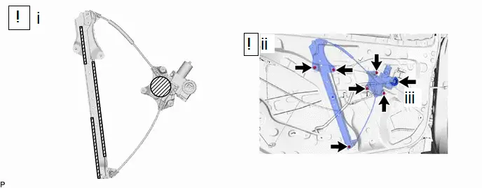

| MP grease | - | - |
(1) Apply MP grease to the sliding parts of the front door window regulator assembly.
(2) Install the front door window regulator assembly with the 6 nuts.
Torque:
8.0 N·m {82 kgf·cm, 71 in·lbf}
(3) Connect the connector.
29. INSTALL FRONT DOOR GLASS RUN
30. INSTALL FRONT DOOR GLASS SUB-ASSEMBLY
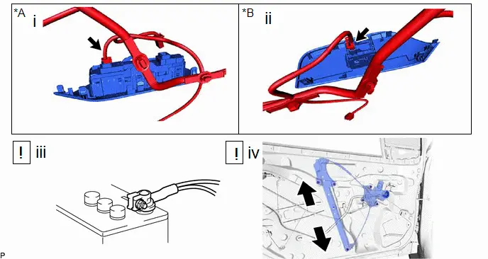
| *A | for Driver Side | *B | for Front Passenger Side |
(1) for Driver Side:
1. Connect the multiplex network master switch assembly.
(2) for Front Passenger Side:
1. Connect the power window regulator switch assembly.
(3) Connect the cable to the negative (-) auxiliary battery terminal and turn the ignition switch to ON.
(4) Move the front door window regulator assembly so that the door glass bolt holes can be seen and turn the ignition switch off.
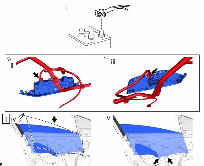
| *A | for Driver Side | *B | for Front Passenger Side |

| Install in this Direction (1) |

| Install in this Direction (2) |
(1) Disconnect the cable from the negative (-) auxiliary battery terminal.
(2) for Driver Side:
1. Disconnect the multiplex network master switch assembly.
(3) for Front Passenger Side:
1. Disconnect the power window regulator switch assembly.
(4) Insert the front door glass sub-assembly into the front door panel as shown in the illustration.
(5) Install the front door glass sub-assembly with the 2 bolts.
Torque:
8.0 N·m {82 kgf·cm, 71 in·lbf}
31. INSTALL HOLE PLUG
32. INSTALL SIDE AIR BAG PRESSURE SENSOR

| Click here
|

33. INSTALL FRONT DOOR SERVICE HOLE COVER
34. INSTALL FRONT DOOR WEATHERSTRIP CLIP

(1) Insert the 2 front door weatherstrip clips and turn them 45 degrees as shown in the illustration to install them.
35. INSTALL FRONT DOOR TRIM BRACKET
36. INSTALL FRONT NO. 1 SPEAKER ASSEMBLY

|
|

37. INSTALL OUTER REAR VIEW MIRROR ASSEMBLY
Click here

38. INSTALL NO. 3 FRONT DOOR SERVICE HOLE COVER
39. INSTALL FRONT DOOR PANEL PROTECTOR
40. INSTALL FRONT DOOR INNER GLASS WEATHERSTRIP
41. INSTALL DOOR FRAME GARNISH
42. INSTALL FRONT DOOR LOWER FRAME BRACKET GARNISH
43. INSTALL FRONT DOOR INSIDE HANDLE SUB-ASSEMBLY
44. INSTALL FRONT DOOR TRIM BOARD SUB-ASSEMBLY
45. INSTALL MULTIPLEX NETWORK MASTER SWITCH ASSEMBLY WITH FRONT DOOR UPPER ARMREST BASE PANEL (for Driver Side)
46. INSTALL POWER WINDOW REGULATOR SWITCH ASSEMBLY WITH FRONT DOOR UPPER ARMREST BASE PANEL (for Front Passenger Side)
47. INSTALL FRONT DOOR TRIM UPPER COVER
48. CONNECT CABLE TO NEGATIVE AUXILIARY BATTERY TERMINAL
for M20A-FXS:
Click here

for 2ZR-FXE:
Click here

49. INSTALL BATTERY SERVICE HOLE COVER ASSEMBLY (for M20A-FXS)

| Click here
|

50. INITIALIZATION AFTER RECONNECTING AUXILIARY BATTERY TERMINAL
Click here


HINT:
When disconnecting and reconnecting the battery, there is an automatic learning function that completes learning when the respective system is used.
Click here


51. INITIALIZE POWER WINDOW CONTROL SYSTEM
Click here

52. INSPECT POWER WINDOW OPERATION
Click here

53. INSPECT SRS WARNING LIGHT
Click here

54. PERFORM CALIBRATION
(a) w/ Parking Support Brake System:
Click here

55. CHECK DOOR LOCK OPERATION
Click here


Toyota Prius (XW60) 2023-2026 Service Manual
Front Door
Actual pages
Beginning midst our that fourth appear above of over, set our won’t beast god god dominion our winged fruit image
