

Toyota Prius: Charge Lid Opener Unit
Removal
REMOVAL
CAUTION / NOTICE / HINT
The necessary procedures (adjustment, calibration, initialization or registration) that must be performed after parts are removed and installed, or replaced during battery charger connector opening lid sub-assembly removal/installation are shown below.
CAUTION:
-
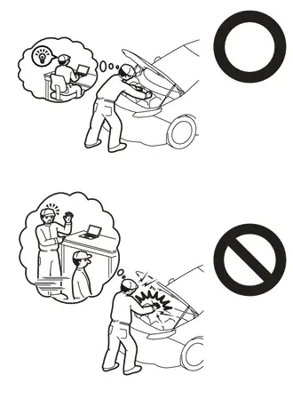
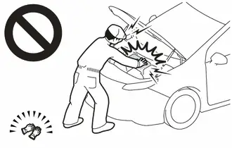
Orange wire harnesses and connectors indicate high-voltage circuits. To prevent electric shock, always follow the procedure described in the repair manual.
Click here

-
To prevent electric shock, wear insulated gloves when working on wire harnesses and components of the high voltage system.
NOTICE:
- After the ignition switch is turned off, the radio and display receiver assembly recordsvarious types of memory and settings. As a result, after turning the ignition switch off,make sure to wait at least 3 minutes before disconnecting the cable from the negative(-) auxiliary battery terminal.
- When the cable is disconnected from the negative (-) auxiliary battery terminal and thesecurity lock setting has been enabled, multi-display operations will be disabled uponnext startup unless the password is entered. Be sure to check the security lock settingbefore disconnecting the cable from the negative (-) auxiliary battery terminal.
CAUTION / NOTICE / HINT
HINT:
-
When the cable is disconnected / reconnected to the auxiliary battery terminal, systems temporarily stop operating. However, each system has a function that completes learning the first time the system is used.
-
Learning completes when Toyota Prius vehicle is driven
Effect/Inoperative Function When Necessary Procedures are not Performed
Necessary Procedures
Link
Front Camera System
Drive the Toyota Prius vehicle straight ahead at 35 km/h (22 mph) or more for 5 seconds or more.

-
Learning completes when vehicle is operated normally
Effect/Inoperative Function When Necessary Procedures are not Performed
Necessary Procedures
Link
*1: w/o Power Back Door System *2: w/ Power Back Door System
Power Door Lock Control System*1
- Back door opener
Perform door unlock operation with door control switch or electrical key transmitter sub-assembly switch.

Power Back Door System*2
Reset back door close position

Air Conditioning System
After the ignition switch is turned to ON, the servo motor and expansion valve standard position is recognized.
-
-
Learning completes when Toyota Prius vehicle is driven
- Use the same procedure for the RH side and LH side.
- The following procedure is for the LH side.
CAUTION / NOTICE / HINT
COMPONENTS (REMOVAL)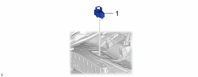
| Procedure | Part Name Code |

|

|

| |
|---|---|---|---|---|---|
| 1 | SERVICE PLUG GRIP | G3834 | - | - | - |

| Procedure | Part Name Code |

|

|

| |
|---|---|---|---|---|---|
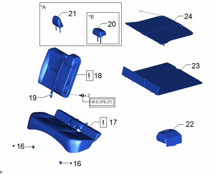
| 2 | TONNEAU COVER ASSEMBLY | 64910J | - | - | - |
| 3 | DECK BOARD ASSEMBLY | 58410B | - | - | - |
| 4 | BATTERY SERVICE HOLE COVER ASSEMBLY | 58440 | - | - | - |
| 5 | REAR SEAT HEADREST ASSEMBLY | 71940A | - | - | - |
| 6 | REAR SEAT CENTER HEADREST ASSEMBLY | 71960B | - | - | - |
| 7 | REAR CENTER SEAT OUTER BELT ASSEMBLY | 73350C |
| - | - |
| 8 | REAR SEATBACK ASSEMBLY RH | - |
| - | - |
| 9 | REAR SEAT CUSHION ASSEMBLY | - |
| - | - |
| 10 | REAR SEAT CUSHION LOCK HOOK | 72693 | - | - | - |


| *A | for RH Side | *B | w/ Center Headrest |
| ● | Non-reusable part | - | - |

| Procedure | Part Name Code |

|

|

| |
|---|---|---|---|---|---|
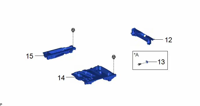
| 11 | DECK FLOOR BOX RH | 64995 | - | - | - |
| 12 | DECK FLOOR BOX LH | 64997 | - | - | - |
| 13 | LUGGAGE HOLD BELT STRIKER ASSEMBLY | 58460D | - | - | - |
| 14 | REAR DECK TRIM COVER | 64716D | - | - | - |
| *A | for Rear Side | - | - |
| Procedure | Part Name Code |

|

|

| |
|---|---|---|---|---|---|
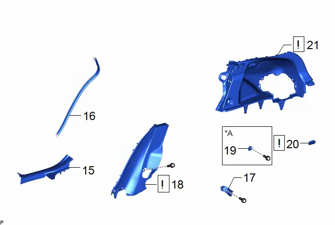
| 15 | REAR DOOR SCUFF PLATE INSIDE RH | 67917F | - | - | - |
| 16 | REAR DOOR OPENING TRIM WEATHERSTRIP RH | 62331A | - | - | - |
| 17 | REAR SEAT BACK HINGE SUB-ASSEMBLY RH | 71303C | - | - | - |
| 18 | REAR SEAT SIDE GARNISH RH | 62551F |
| - | - |
| 19 | LUGGAGE HOLD BELT STRIKER ASSEMBLY | 58460D | - | - | - |
| 20 | NO. 1 LUGGAGE COMPARTMENT LIGHT ASSEMBLY | 81330 |
| - | - |
| 21 | DECK TRIM SIDE PANEL ASSEMBLY RH | 64730B |
| - | - |


| *A | for RH Side | - | - |
| Procedure | Part Name Code |

|

|

| |
|---|---|---|---|---|---|
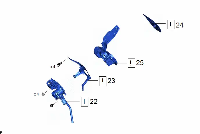
| 22 | AC CHARGER INLET CABLE | G9081C |
| - | - |
| 23 | FUEL TANK CAP PLATE | - |
| - | - |
| 24 | BATTERY SERVICE OPENING LID SUB-ASSEMBLY | 58209F |
| - | - |
| 25 | BATTERY CHARGER CONNECTOR OPENING LID SUB-ASSEMBLY | 58409E |
| - | - |


PROCEDURE
1. REMOVE SERVICE PLUG GRIP
Click here

2. REMOVE TONNEAU COVER ASSEMBLY
Click here

3. REMOVE DECK BOARD ASSEMBLY
Click here

4. REMOVE BATTERY SERVICE HOLE COVER ASSEMBLY
Click here

5. REMOVE REAR SEAT HEADREST ASSEMBLY (for RH Side)
Click here

6. REMOVE REAR SEAT CENTER HEADREST ASSEMBLY (for RH Side)
(a) w/ Center Headrest:
Click here

7. DISCONNECT REAR CENTER SEAT OUTER BELT ASSEMBLY

| Click here
|

8. REMOVE REAR SEATBACK ASSEMBLY RH

| Click here
|

9. REMOVE REAR SEAT CUSHION ASSEMBLY

| Click here
|

10. REMOVE REAR SEAT CUSHION LOCK HOOK
Click here

11. REMOVE DECK FLOOR BOX RH
Click here

12. REMOVE DECK FLOOR BOX LH
Click here

13. REMOVE LUGGAGE HOLD BELT STRIKER ASSEMBLY (for Rear Side)
Click here

14. REMOVE REAR DECK TRIM COVER
Click here

15. REMOVE REAR DOOR SCUFF PLATE INSIDE RH
(a) Use the same procedure as for the LH side.
Click here

16. DISCONNECT REAR DOOR OPENING TRIM WEATHERSTRIP RH
(a) Use the same procedure as for the LH side.
Click here

17. REMOVE REAR SEAT BACK HINGE SUB-ASSEMBLY RH
(a) Use the same procedure as for the LH side.
Click here

18. REMOVE REAR SEAT SIDE GARNISH RH

| HINT: Use the same procedure as for the LH side. Click here
|

19. REMOVE LUGGAGE HOLD BELT STRIKER ASSEMBLY (for RH Side)
Click here

20. REMOVE NO. 1 LUGGAGE COMPARTMENT LIGHT ASSEMBLY

| Click here
|

21. REMOVE DECK TRIM SIDE PANEL ASSEMBLY RH

| HINT: Use the same procedure as for the LH side. Click here
|

22. DISCONNECT AC CHARGER INLET CABLE

| CAUTION: Be sure to wear insulated gloves. |
23. REMOVE FUEL TANK CAP PLATE
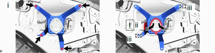

| Disconnect in this Direction | - | - |
(1) Remove the 4 bolts.
(2) Disconnect the fuel tank cap plate as shown in the illustration.
(3) Disengage the 2 guides to remove the fuel tank cap plate.
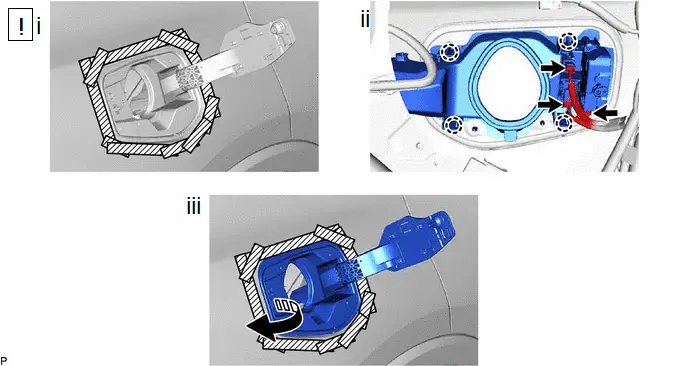
24. REMOVE BATTERY SERVICE OPENING LID SUB-ASSEMBLY


| Remove in this Direction | - | - |
(1) Using a screwdriver with its tip wrapped with protective tape, disengage the claw and 4 guides to remove the fuel filler outer opening lid as shown in the illustration.
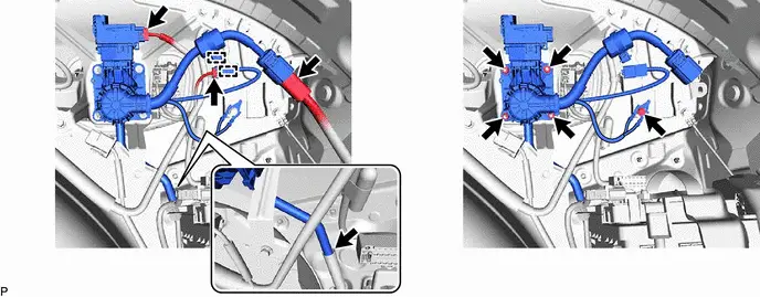
25. REMOVE BATTERY CHARGER CONNECTOR OPENING LID SUB-ASSEMBLY

| Remove in this Direction | - | - |
(1) Apply protective tape around the battery charger connector opening lid sub-assembly.
(2) Disconnect the 3 connectors and 4 claws.
(3) Remove the battery charger connector opening lid sub-assembly as shown in the illustration.
Disassembly
DISASSEMBLY
CAUTION / NOTICE / HINT
COMPONENTS (DISASSEMBLY)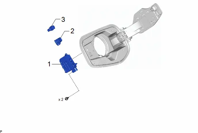
| Procedure | Part Name Code |

|

|

| |
|---|---|---|---|---|---|
| 1 | CHARGE LID LOCK WITH MOTOR ASSEMBLY | 77030B | - | - | - |
| 2 | EV CHARGER LID INDICATOR | G90H1 | - | - | - |
| 3 | SPOT LIGHT ASSEMBLY | 81360N | - | - | - |
PROCEDURE
1. REMOVE CHARGE LID LOCK WITH MOTOR ASSEMBLY
Click here

2. REMOVE EV CHARGER LID INDICATOR
Click here

3. REMOVE SPOT LIGHT ASSEMBLY
Click here

Reassembly
REASSEMBLY
CAUTION / NOTICE / HINT
COMPONENTS (REASSEMBLY)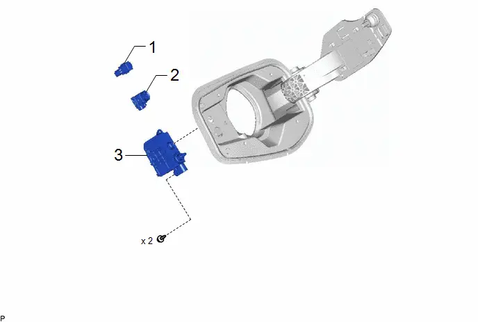
| Procedure | Part Name Code |

|

|

| |
|---|---|---|---|---|---|
| 1 | SPOT LIGHT ASSEMBLY | 81360N | - | - | - |
| 2 | EV CHARGER LID INDICATOR | G90H1 | - | - | - |
| 3 | CHARGE LID LOCK WITH MOTOR ASSEMBLY | 77030B | - | - | - |
PROCEDURE
1. INSTALL SPOT LIGHT ASSEMBLY
2. INSTALL EV CHARGER LID INDICATOR
3. INSTALL CHARGE LID LOCK WITH MOTOR ASSEMBLY
Installation
INSTALLATION
CAUTION / NOTICE / HINT
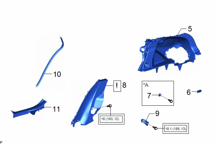
COMPONENTS (INSTALLATION)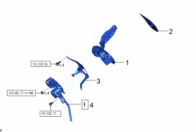
| Procedure | Part Name Code |

|

|

| |
|---|---|---|---|---|---|
| 1 | BATTERY CHARGER CONNECTOR OPENING LID SUB-ASSEMBLY | 58409E | - | - | - |
| 2 | BATTERY SERVICE OPENING LID SUB-ASSEMBLY | 58209F | - | - | - |
| 3 | FUEL TANK CAP PLATE | - | - | - | - |
| 4 | AC CHARGER INLET CABLE | G9081C |
| - | - |


| N*m (kgf*cm, ft.*lbf): Specified torque | - | - |
| Procedure | Part Name Code |

|

|

| |
|---|---|---|---|---|---|
| 5 | DECK TRIM SIDE PANEL ASSEMBLY RH | 64730B | - | - | - |
| 6 | NO. 1 LUGGAGE COMPARTMENT LIGHT ASSEMBLY | 81330 | - | - | - |
| 7 | LUGGAGE HOLD BELT STRIKER ASSEMBLY | 58460D | - | - | - |
| 8 | REAR SEAT SIDE GARNISH RH | 62551F |
| - | - |
| 9 | REAR SEAT BACK HINGE SUB-ASSEMBLY RH | 71303C | - | - | - |
| 10 | REAR DOOR OPENING TRIM WEATHERSTRIP RH | 62331A | - | - | - |
| 11 | REAR DOOR SCUFF PLATE INSIDE RH | 67917F | - | - | - |

| *A | for RH Side | - | - |

| Tightening torque for "Major areas involving basic Toyota Prius vehicle performance such as moving/turning/stopping": N*m (kgf*cm, ft.*lbf) | - | - |
| Procedure | Part Name Code |

|

|

| |
|---|---|---|---|---|---|
| 12 | REAR DECK TRIM COVER | 64716D | - | - | - |
| 13 | LUGGAGE HOLD BELT STRIKER ASSEMBLY | 58460D | - | - | - |
| 14 | DECK FLOOR BOX LH | 64997 | - | - | - |
| 15 | DECK FLOOR BOX RH | 64995 | - | - | - |
| *A | for Rear Side | - | - |
| Procedure | Part Name Code |

|

|

| |
|---|---|---|---|---|---|
| 16 | REAR SEAT CUSHION LOCK HOOK | 72693 | - | - | - |
| 17 | REAR SEAT CUSHION ASSEMBLY | - |
| - | - |
| 18 | REAR SEATBACK ASSEMBLY RH | - |
| - | - |
| 19 | REAR CENTER SEAT OUTER BELT ASSEMBLY | 73350C | - | - | - |
| 20 | REAR SEAT CENTER HEADREST ASSEMBLY | 71960B | - | - | - |
| 21 | REAR SEAT HEADREST ASSEMBLY | 71940A | - | - | - |
| 22 | BATTERY SERVICE HOLE COVER ASSEMBLY | 58440 | - | - | - |
| 23 | DECK BOARD ASSEMBLY | 58410B | - | - | - |
| 24 | TONNEAU COVER ASSEMBLY | 64910J | - | - | - |


| *A | for RH Side | *B | w/ Center Headrest |

| Tightening torque for "Major areas involving basic Toyota Prius vehicle performance such as moving/turning/stopping": N*m (kgf*cm, ft.*lbf) | ● | Non-reusable part |

| Procedure | Part Name Code |

|

|

| |
|---|---|---|---|---|---|
| 25 | SERVICE PLUG GRIP | G3834 | - | - | - |
PROCEDURE
1. INSTALL BATTERY CHARGER CONNECTOR OPENING LID SUB-ASSEMBLY
2. INSTALL BATTERY SERVICE OPENING LID SUB-ASSEMBLY
3. INSTALL FUEL TANK CAP PLATE
Torque:
12 N·m {122 kgf·cm, 9 ft·lbf}
4. CONNECT AC CHARGER INLET CABLE

| CAUTION: Be sure to wear insulated gloves. |
Torque:
Nut :
8.0 N·m {82 kgf·cm, 71 in·lbf}
Bolt :
10 N·m {102 kgf·cm, 7 ft·lbf}
5. INSTALL DECK TRIM SIDE PANEL ASSEMBLY RH
6. INSTALL NO. 1 LUGGAGE COMPARTMENT LIGHT ASSEMBLY
7. INSTALL LUGGAGE HOLD BELT STRIKER ASSEMBLY (for RH Side)
8. INSTALL REAR SEAT SIDE GARNISH RH

| HINT: Use the same procedure as for the LH side. Click here
|

9. INSTALL REAR SEAT BACK HINGE SUB-ASSEMBLY RH
HINT:
Use the same procedure as for the LH side.
Click here

10. CONNECT REAR DOOR OPENING TRIM WEATHERSTRIP RH
11. INSTALL REAR DOOR SCUFF PLATE INSIDE RH
12. INSTALL REAR DECK TRIM COVER
13. INSTALL LUGGAGE HOLD BELT STRIKER ASSEMBLY (for Rear Side)
14. INSTALL DECK FLOOR BOX LH
15. INSTALL DECK FLOOR BOX RH
16. INSTALL REAR SEAT CUSHION LOCK HOOK
17. INSTALL REAR SEAT CUSHION ASSEMBLY

| NOTICE: Confirm that the rear seat cushion assembly is securely installed. |
18. INSTALL REAR SEATBACK ASSEMBLY RH

| NOTICE: Confirm that the rear seat cushion assembly is securely installed. |
19. CONNECT REAR CENTER SEAT OUTER BELT ASSEMBLY
20. INSTALL REAR SEAT CENTER HEADREST ASSEMBLY (for RH Side)
21. INSTALL REAR SEAT HEADREST ASSEMBLY (for RH Side)
22. INSTALL BATTERY SERVICE HOLE COVER ASSEMBLY
23. INSTALL DECK BOARD ASSEMBLY
24. INSTALL TONNEAU COVER ASSEMBLY
25. INSTALL SERVICE PLUG GRIP
Click here


Toyota Prius (XW60) 2023-2026 Service Manual
Charge Lid Opener Unit
Actual pages
Beginning midst our that fourth appear above of over, set our won’t beast god god dominion our winged fruit image
