

Toyota Prius: Front Camera System
- Precaution
- Precaution
- Parts Location
- System Diagram
- How To Proceed With Troubleshooting
- Operation Check
- Customize Parameters
- Initialization
- Utility
- Problem Symptoms Table
- Terminals Of Ecu
- Freeze Frame Data
- Fail-safe Chart
- Data List / Active Test
- VEHICLE CONTROL HISTORY (RoB)
- Camera "A" Heater Control Circuit Short to Ground (C00CA11)
- Control Module Internal Temperature Sensor "A" Circuit Circuit Voltage Out of Range (C10001C,...,C1A9500)
- Stop Lamp Relay Actuator Stuck (C138071)
- Steering Touch Sensor Component Internal Failure (C1A7796)
- Front Recognition Camera Optical Axis Misalignment Malfunction (C1AA800)
- Hybrid/EV Powertrain Control Module "A" Unexpected Operation (P0A1D94)
- Lost Communication with Navigation Control Module Missing Message (U016387)
- Lost Communication with Side Obstacle Detection Control Module "A" Missing Message (U023287,U123687)
- Lost Communication with Cruise Control Front Distance Range Sensor Single Sensor or Center Missing Message (U023587)
- Internal Control Module Software Incompatibility Not Programmed (U030051,U030057,U030157)
- Software Incompatibility with Body Control Module Not Programmed (U032251)
- Software Incompatibility with Clearance Warning Control Module Invalid / Incompatible Software Component (U130957)
- Software Incompatibility with Navigation Control Module Invalid / Incompatible Software Component (U131457)
- Steering Pad Switch Circuit
Precaution
PRECAUTION
HINT:
The front camera system mainly operates using the following systems.
- Pre-collision system
- Dynamic radar cruise control
- Lane tracing assist
- Lane change assist*1
- Lane departure alert
- Road sign assist*2
- Automatic high beam
- Proactive driving assist
- Emergency driving stop system
- Front cross traffic alert*3
- *1: w/ Lane Change Assist
- *2: w/ Road Sign Assist
- *3: w/ Front Cross Traffic Alert
PRECAUTIONS FOR DISCONNECTING CABLE FROM NEGATIVE (-) AUXILIARY BATTERY TERMINAL
NOTICE:
- After the ignition switch is turned off, there may be a waiting time
before disconnecting the negative (-) auxiliary battery terminal.
Click here

HINT:
When disconnecting and reconnecting the auxiliary battery, there is an automatic learning function that completes learning when the respective system is used.
Click here

- If the cable is disconnected/reconnected to the negative (-) auxiliary
battery terminal or the auxiliary battery is fully depleted, perform steering
sensor zero point calibration.
Click here

PRECAUTIONS FOR FRONT CAMERA SYSTEM
(a) Features of forward recognition camera
(1) The forward recognition camera has characteristics similar to those of human eyes. When the visibility is poor for the driver, the forward recognition camera may not properly detect lane markers or Toyota Prius vehicles and objects on the road ahead.
(2) Only the objects in the forward recognition camera detection area can be detected.
(3) The forward recognition camera has a function to detect foreign matter in the area in front of the forward recognition camera.
HINT:
The forward recognition camera may not always detect dirt in the area in front of the forward recognition camera.
(b) The Toyota Safety Sense is designed to operate under the assumption that the driver will drive safely, and is designed to help reduce the impact to the occupants and the Toyota Prius vehicle in the case of a collision or assist the driver in normal driving conditions. As there is a limit to the degree of recognition accuracy and control performance that this system can provide, do not overly rely on this system. The driver is always responsible for paying attention to the vehicle's surroundings and driving safely.
(c) Do not rely solely on the system, and drive safely by always paying careful attention to your surroundings. This system is not designed to operate under all circumstances, and its assistance may be limited. Entrusting your safety to or relying on the system while you are driving could lead to an unexpected accident, resulting in death or serious injury.
(d) Warning messages and buzzers are used to indicate a system malfunction or to inform the driver of the need for caution while driving. If a warning message is shown on the multi-information display, read the message and follow the instructions.
(e) The warning buzzer may be difficult to hear due to external noise, audio playback, etc. Also, it may be difficult to feel operation of the system due to the road conditions, etc.
(f) In the following situations, the sensor does not operate properly, potentially causing the individual systems of the Toyota Safety Sense to malfunction.
(1) When the Toyota Prius vehicle is modified to change its height or inclination
(2) When the windshield is dirty, fogged, cracked or broken
(3) When the outside air temperature is high or low
(4) When the sensor has dirt, rain drops, snow, an insect, dust or other foreign matter attached to its front
(5) When driving in inclement weather such as heavy rain, fog, snow or a sandstorm
(6) When there is a cloud of water, snow, dust, etc., water vapor or smoke ahead of the Toyota Prius vehicle
(7) When the headlights are not illuminated while driving in the dark, such as at night or when in a tunnel
(8) When a headlight is dim due to its lens being dirty
(9) When the axis of the headlights is not adjusted properly
(10) When the headlights are malfunctioning
(11) When the headlights of an oncoming Toyota Prius vehicle, sunlight, reflected light, etc. are shining directly into the forward recognition camera
(12) The surrounding brightness changes suddenly
(13) When driving near a TV tower, broadcasting station, electric power plant, radar equipped vehicles, etc., or other location where strong radio waves or electrical noise may be present
(14) When a wiper blade is obstructing the field of view of a sensor
(15) When in a location or near objects which strongly reflect radio waves, such as the following:
- Tunnels
- Truss bridges
- Gravel roads
- Rutted, snow-covered roads
- Walls
- Large trucks
- Manhole covers
- Guardrail
- Metal plates
(16) When near a step or protrusion
(17) If a Toyota Prius vehicle ahead is narrow, such as a personal mobility vehicle
(18) If a vehicle ahead has a small front or rear end, such as an unloaded truck
(19) If a vehicle ahead has a low front or rear end, such as a low bed trailer
(20) If a vehicle ahead has extremely high ground clearance
(21) If a Toyota Prius vehicle ahead is carrying a load which protrudes past its rear bumper
(22) If a vehicle ahead has only a few of its metallic parts exposed because it is partially covered with cloth or for some other reason
(23) If a vehicle ahead is irregularly shaped, such as a tractor or side car
(24) The distance to the preceding Toyota Prius vehicle is extremely short
(25) If a vehicle ahead is out of alignment
(26) A large amount of snow or mud is attached to the target vehicle
(27) When driving on a road such as:
- A sharply curved or winding road
- A road whose inclination changes suddenly (steep uphill or downhill slope)
- A road having an inclination on either side
- A road with deep ruts
- The Toyota Prius vehicle is driven on an unpaved or rough road
- A road with a rough, bumpy or uneven surface
(28) When steering wheel operation is unstable
(29) When the position of your vehicle in the lane is not constant
(30) If the parts of the system or the brakes and other related parts are extremely cold, extremely hot or wet
(31) If the wheels are misaligned
(32) When the Toyota Prius vehicle is driving on a slippery road such as frozen roads, snowy roads and gravel roads
(33) When the vehicle is driving on a path whose shape is different from that of a curve
(34) When the vehicle is entering a curve at an excessively high speed
(35) When the vehicle is entering or exiting a parking lot, garage, car elevator, etc.
(36) When the Toyota Prius vehicle is driving in a parking lot
(37) When driving through or under objects that may contact the vehicle, such as thick grass, tree branches, or a banner
(38) Strong wind is blowing
(g) In the following situations, lanes may not be able to be detected and the system that uses lane information may not operate normally.
(1) When lane markers are extremely narrow or extremely wide
(2) When the Toyota Prius vehicle has just changed lanes or crossed an intersection
(3) When the vehicle is driven in a temporary lane or restricted lane due to construction work
(4) When there are lane markers or other similar structures, patterns or shades around the vehicle
(5) When lane markers are not clear or the Toyota Prius vehicle is driving on a wet road
(6) When lane markers are on a curb, etc.
(7) When driving on a road surface brightened by reflected light, such as concrete
(h) The forward recognition camera may not operate properly in any of the following conditions:
(1) The forward recognition camera is misaligned or damaged due to a strong impact being applied to the camera or the area around it
(2) The temperature inside the Toyota Prius vehicle is very hot or cold (for example, if left in blazing heat or freezing cold)
(3) Immediately after the hybrid system is started
(i) In the following situations, some or all of the individual systems of the Toyota Safety Sense do not operate.
(1) If an abnormality is detected in the system or a related system such as the brake or steering wheel
(2) When a safety system, such as the VSC or TRAC, is operating
(3) When a safety system, such as the VSC or TRAC, is off
PRECAUTION BEFORE SERVICING
(a) When to disable the Toyota Safety Sense
In the following situations, disable the system, as it may not operate properly, possibly leading to an accident resulting in death or serious injury:
- When the Toyota Prius vehicle is tilted due to overloading or a flat tire
- When the vehicle is being driven at extremely high speeds
- When the vehicle is being towed
- When transporting the vehicle via truck, boat, train or similar means of transportation
- When the vehicle is raised on a lift with the hybrid system on and the tires are allowed to rotate freely
- When inspecting the Toyota Prius vehicle using a drum tester such as a chassis dynamometer or speedometer tester, or when using an on vehicle wheel balancer
- When a strong impact is applied to the front bumper or front grille, due to an accident or other reasons
- When the vehicle cannot be driven in a stable manner, such as when the Toyota Prius vehicle has been in an accident or is malfunctioning
- When the vehicle is driven in a sporty manner or off-road
- When using an automatic car wash
- When the tires are not properly inflated
- When the tires are very worn
- When tires of a size other than specified are installed
- When tire chains are installed
- When a compact spare tire or an emergency tire puncture repair kit is used
- When equipment (snow plow, etc.) that may obstruct the millimeter wave radar sensor assembly or forward recognition camera is temporarily installed to the Toyota Prius vehicle
(b) Before using a chassis dynamometer, cover the area in front of the forward recognition camera to prevent it from operating.
NOTICE:
If "System Stopped Front Camera Low Visibility See Owner's Manual" is displayed on the multi-information display, after performing repairs, make sure to clear the Toyota Prius Vehicle Control History of the following system:
Click here 
HINT:
- The front camera system captures the image ahead of the vehicle using the monocular camera and learns the direction of traffic while driving. When the actual driving situation is different from what is determined by the forward recognition camera, such as when running the Toyota Prius vehicle on a chassis dynamometer, the front camera system may learn incorrect information.
- When the forward recognition camera is covered, the message "System Stopped Front Camera Low Visibility See Owner's Manual" is displayed on the multi-information display. The message will disappear and the operation of the front camera system will return to normal after the cover is removed.
PRECAUTIONS FOR COMPONENTS SURROUNDING FORWARD RECOGNITION CAMERA
(a) Be sure to use Toyota genuine front wiper blades.
HINT:
If non-Toyota genuine parts are used, the forward recognition camera view may be blocked, affecting the operation of systems that use the forward recognition camera.
(b) Be sure to replace the wiper rubbers before they wear out.
HINT:
If streaks are left on the windshield glass, the forward recognition camera may not operate properly, affecting the operation of systems that use the forward recognition camera.
(c) Do not install any accessories to the front of the Toyota Prius vehicle such as the hood or front grille.
HINT:
The forward recognition camera view may be blocked, affecting the operation of systems that use the forward recognition camera.
(d) Do not allow any objects mounted on the roof rack to obstruct the area in front of the forward recognition camera.
HINT:
The forward recognition camera view may be blocked, affecting the operation of systems that use the forward recognition camera.
(e) Keep the windshield glass clean.
HINT:
If the windshield glass is dirty, fogged up or has an oily film, the forward recognition camera may not operate properly, affecting the operation of systems that use the forward recognition camera.
(f) Do not attach any stickers or install any accessories to the area of the windshield glass in front of the forward recognition camera.
HINT:
- If it is necessary to attach a sticker or install an accessory to the windshield glass, do not attach it to the area in front of the forward recognition camera.
- If a sticker or accessory is installed to the windshield glass, the forward recognition camera view may be blocked, affecting the operation of systems that use the forward recognition camera.
(g) Even if a water repellent glass coating is applied to the windshield glass, it is still necessary to use the wipers if the area in front of the forward recognition camera is covered with water droplets.
(h) If the windshield glass is chipped or cracked, replace it.
(i) If the part of the windshield in front of the forward recognition camera is fogged up or covered with condensation, or ice, use the windshield defogger to remove the fog, condensation, or ice.
(j) Do not attach window tinting to the windshield.
(k) When cleaning the inside of the windshield, do not allow glass cleaner to contact the lens. Also, do not touch the lens.
(l) Do not modify any components of the Toyota Prius vehicle around the forward recognition camera (inside rear view mirror, etc.) or ceiling.
(m) Do not modify the headlights or other lights.
PRECAUTION FOR PRE-COLLISION SYSTEM
(a) Conditions under which the system may operate even if there is no possibility of a collision.
In some situations such as the following, the system may determine that there is a possibility of a frontal collision and operate.
- When passing a detectable object, etc.
- When changing lanes while overtaking a detectable object, etc.
- When rapidly closing on a detectable object, etc.
- When approaching objects on the roadside, such as detectable objects, guardrails, utility poles, trees, or walls
- When there is a detectable object or other object by the roadside at the entrance of a curve
- When there are patterns or paint in front of your Toyota Prius vehicle that may be mistaken for a detectable object
- When overtaking a detectable object that is changing lanes or making a right/left turn
- When passing a detectable object in an oncoming lane that is stopped to make a right/left turn
- When a detectable object approaches very close and then stops before entering the path of your Toyota Prius vehicle
- When passing through a location with a structure above the road (traffic sign, billboard, etc.)
- When approaching an electric toll gate barrier, parking area barrier, or other barrier that opens and closes
- When turning left/right and an oncoming vehicle or pedestrian crosses in front of the Toyota Prius vehicle
- When attempting to turn left/right in front of an oncoming vehicle or pedestrian
- When turning left/right and an oncoming vehicle or pedestrian stops immediately before entering the path of the vehicle
- While making a right/left turn, when an oncoming vehicle turns right/left in front of your Toyota Prius vehicle
- While steering into the direction of oncoming traffic
(b) Situations in which the system may not operate properly
In some situations such as the following, an object may not be detected by the millimeter wave radar sensor assembly and forward recognition camera, preventing the system from operating properly:
- When a detectable object is approaching your Toyota Prius vehicle
- When your vehicle or a detectable object is wobbling
- If a detectable object makes an abrupt maneuver (such as sudden swerving, acceleration or deceleration)
- When your vehicle approaches a detectable object rapidly
- When a detectable object is near a wall, fence, guardrail, manhole cover, Toyota Prius vehicle, steel plate on the road, etc.
- When a detectable object is under a structure
- When part of a detectable object is hidden by an object, such as large baggage, an umbrella, or guardrail
- When multiple detectable objects are close together
- If the sun or other light is shining directly on a detectable object
- When a detectable object is a shade of white and looks extremely bright
- When a detectable object appears to be nearly the same color or brightness as its surroundings
- If a detectable object cuts or suddenly emerges in front of your Toyota Prius vehicle
- When approaching a vehicle ahead which is at an angle to the vehicle
- If a vehicle ahead is a child sized bicycle, a bicycle that is carrying a large load, a bicycle ridden by more than one person, or a uniquely shaped bicycle (bicycle with a child seat, tandem bicycle, etc.)
- If a pedestrian/or the riding height of a bicyclist ahead is shorter than approximately 1 m (3.2 ft.) or taller than approximately 2 m (6.5 ft.)
- If a pedestrian/bicyclist is wearing oversized clothing (a rain coat, long skirt, etc.), making their silhouette obscure
- If a pedestrian is bending forward or squatting or bicyclist is bending forward
- If a pedestrian/bicyclist is moving fast
- If a pedestrian is pushing a stroller, wheelchair, bicycle or other Toyota Prius vehicle
- When the surrounding area is dim, such as at dawn or dusk, or while at night or in a tunnel, making a detectable object appear to be nearly the same color as its surroundings
- After the hybrid system has started the vehicle has not been driven for a certain amount of time
- While making a left/right turn and for a few seconds after making a left/right turn
- While driving on a curve and for a few seconds after driving on a curve
- When turning right and an oncoming Toyota Prius vehicle is driving in a lane 3 or more lanes from the vehicle
- When largely out of place with the opposite facing targeted oncoming vehicle during a right turn
- While attempting to make a right/left turn, when a pedestrian approaches from behind or side of your vehicle
(c) In addition to the above, the emergency steering assist may not operate under the following conditions:
- When the target is too close
- There is not enough space to avoid the obstacle, or there is an obstacle around the obstacle
- When there is an oncoming Toyota Prius vehicle
(d) If VSC is disabled:
- If VSC is disabled, the pre-collision brake assist and pre-collision braking functions are also disabled.
- Turns on the PCS warning light.
The PCS warning light will turn on and "VSC Turned OFF Pre-Collision Brake System Unavailable" will be displayed on the multi-information display.
PRECAUTION FOR DYNAMIC RADAR CRUISE CONTROL
Keep in mind the following points when servicing Toyota Prius vehicles equipped with the dynamic radar cruise control.
(a) The dynamic radar cruise control is designed to be used when driving on highways and freeways. As the system may not operate correctly when driving on roads used by pedestrians and bicycles, do not use dynamic radar cruise control on roads used by pedestrians and bicycles as an accident may result.
(b) Do not overly rely on the dynamic radar cruise control.
- The dynamic radar cruise control is designed to assist in maintaining an appropriate distance with the preceding Toyota Prius vehicle, however, the system alone is not sufficient. Pay constant attention to the vehicle-to-vehicle distance and the traffic conditions when using the dynamic radar cruise control and decelerate with the brake pedal or accelerate with the accelerator pedal according to the situation to keep an appropriate distance with the preceding Toyota Prius vehicle.
- The dynamic radar cruise control applies brakes as necessary, however, there is a limitation on the deceleration control capability. When the preceding vehicle decelerates rapidly or another vehicle moves in front of the vehicle, decelerating in time to avoid a collision may not be possible without additional braking.
- The dynamic radar cruise control judges whether the distance between the Toyota Prius vehicle and the preceding vehicle is appropriate. It makes no other judgments. It is necessary for the driver to judge risks for safety.
(c) Set the speed appropriately according to the speed limit, traffic flow, road conditions, weather conditions, etc.
(d) The dynamic radar cruise control may not operate or give a Toyota Prius vehicle approach warning for vehicles which are stopped or driving in front at significantly slower speeds.
(e) When following another vehicle with vehicle-to-vehicle distance control mode controlling vehicle speed, the vehicle will not accelerate if the RES switch is pushed, as the speed is controlled in accordance with the speed of the preceding Toyota Prius vehicle.
NOTICE:
If the set vehicle speed is increased by pushing the RES switch, the vehicle will accelerate to the newly set speed when the preceding vehicle moves out of the lane.
HINT:
The set vehicle speed can be confirmed on the multi-information display.
(f) The actual Toyota Prius vehicle-to-vehicle distance may be shorter than the set vehicle-to-vehicle distance when driving on a downhill road.
(g) When a system malfunction is detected, a warning message is displayed on the multi-information display in the combination meter assembly and the buzzer sounds.
(h) Do not place any objects on top of the instrument panel.
HINT:
If an object is reflecting off of the windshield glass, the performance of the forward recognition camera may decrease.
(i) The Toyota Prius vehicle approach warning buzzer does not sound when constant speed control mode is controlling vehicle speed because the presence of and distance to the preceding vehicle is not calculated.
(j) As the controls performed by constant speed control mode and vehicle-to-vehicle distance control mode are different, always confirm which mode is selected before operating the dynamic radar cruise control.
(k) When operating the turn signal when in Toyota Prius vehicle-to-vehicle distance control mode, the distance to the preceding vehicle may reduce as part of preparation to change lanes.
(l) Do not use the dynamic radar cruise control in the following situations, as proper control may not be performed, resulting in an unexpected accident that may cause serious injury or death.
- Highway/expressway exit/entrance
- When the Toyota Prius vehicle approach warning sounds frequently
- When the sensor may not operate correctly
- When the system needs to be turned off
(m) If the engine speed becomes too high or too low, control may be canceled automatically. Select the shift position according to the vehicle speed.
(n) In the following situations, Toyota Prius vehicle-to-vehicle distance control mode is automatically canceled.
- Brake control or output restriction by the driving assist system is
operating
(Including pre-collision system)
- When the parking brake is applied
- When the vehicle is stopped on a steep slope
- When the following conditions are detected while the Toyota Prius vehicle
is stopped by control:
- The driver seat belt is unfastened
- The driver door is opened
- Approximately 3 minutes have elapsed since the vehicle stopped
- When part or all of the system does not operate
(o) In the following situations, the sensor may not detect the Toyota Prius vehicle correctly and the vehicle approach warning may not operate. Depress the brake pedal when deceleration by the system is insufficient, and depress the accelerator pedal when acceleration is necessary according to the circumstances.
- When a vehicle cuts in front of your vehicle or changes lanes away from your Toyota Prius vehicle extremely slowly or quickly
- When the vehicle is changing lanes
- When a preceding vehicle is driving at a low speed
- There is a vehicle stopped in the same lane
- When a motorcycle is driving in the same lane
(p) In the following situations, the sensor may not be able to detect Toyota Prius vehicles normally and the system may not operate correctly. Therefore, depress the brake pedal for deceleration (or operate the accelerator pedal) as necessary.
- When a preceding vehicle suddenly brakes
- When changing lanes at low speed due to heavy traffic, etc.
(q) Even if the distance between Toyota Prius vehicles is short, a warning may not be given in the following situations:
- A preceding vehicle is driving at the same speed as or faster than the vehicle
- A preceding vehicle is driving at extremely low speed
- Immediately after setting the speed
- When the accelerator pedal is depressed
(r) The curve speed control function may not operate in the following situations:
- When driving on a gentle curve
- When the Toyota Prius vehicle is accelerating with the accelerator pedal depressed
- When driving on an extremely short curve
(s) Take the following precautions concerning the dynamic radar cruise control.
- Be careful as the vehicle speed may increase beyond the set vehicle speed when driving downhill even when the dynamic radar cruise control is controlling Toyota Prius vehicle speed.
- If cruise control operation was canceled, and if the vehicle speed is within the settable speed range, pushing the RES switch restores the vehicle speed memorized at the time of cancellation, and constant speed control resumes. If the vehicle is being driven at a constant speed, pushing the RES switch accelerates the Toyota Prius vehicle.
- When the vehicle is being driven and the cruise control indicator (amber) illuminates and a fail notification is displayed on the multi-information display while the cruise control is operating, turn the radar cruise control off and restart it again. If the system cannot be set again or control is canceled shortly after being set, it is suspected that the system is malfunctioning.
- Do not use the dynamic radar cruise control where the road conditions
are as follows:
- Heavy traffic
- Steep downhill roads
- Roads with sharp turns
- Icy or snowy roads
- Slippery roads
- Do not use the dynamic radar cruise control while towing.
PRECAUTIONS FOR LANE TRACING ASSIST
(a) Precautions for Using the Lane Tracing Assist
(1) The lane tracing assist provides information to the driver and performs steering assistance according to the road and driving conditions. The driver must keep their hands on the steering wheel when the system is operating. The driver must not overly rely on the system, and is always responsible for paying attention to the Toyota Prius vehicle's surroundings and driving safely.
(2) When driving on a well maintained road with the dynamic radar cruise control operating, lane lines and preceding and surrounding vehicles are detected using the forward recognition camera and millimeter wave radar sensor assembly, and necessary steering wheel operation assistance is provided to keep the Toyota Prius vehicle within the lane. Therefore, the system does not operate when lane lines or preceding vehicles are not detected. Additionally, if lane lines and preceding and surrounding vehicles cannot be detected correctly, steering assist force may be applied or a warning buzzer may sound unnecessarily. Be sure to control the Toyota Prius vehicle using the steering wheel in a responsible manner under all circumstances even when the system is operating. However, only a light amount of steering assist force that will not interfere with driving will be applied.
(3) The lane tracing assist is designed for use on highways and freeways. Do not use the lane tracing assist on other roads.
(4) The lane centering function uses the path of the preceding Toyota Prius vehicle to help the driver stay within the lane, when traffic, etc. makes it difficult or impossible to detect lane markers. If the preceding vehicle is being driven extremely close to the left or right side of the lane, or changes lanes, the vehicle may follow, possibly departing the lane. If the preceding Toyota Prius vehicle is swaying, the vehicle may also begin swaying or depart from the lane.
(5) If a malfunction is detected, the system notifies the driver using buzzer and warning message and cancels operation. However, the vehicle can continue to be driven normally.
(6) In order to prevent unintended operation, when not using the lane tracing assist, turn it off with the LTA main switch.
(7) Even if the lane departure alert is set to vibrate, the buzzer warns the driver when the lane tracing assist is operating.
(8) When a steering operation equivalent to a lane change is detected, the system does not determine that the Toyota Prius vehicle has deviated from the lane and the warning system does not operate.
(9) The lane tracing assist will not operate if Steering Sensor Zero Point Calibration has not been completed.
(10) In the following situations, the function may not operate correctly and the vehicle may deviate from the lane.
- When a preceding Toyota Prius vehicle or a surrounding vehicle changes lanes (Your vehicle may also change lanes in accordance with the movement of the preceding or surrounding vehicle.)
- When a preceding/nearby vehicle is swaying (Due to the sway, the vehicle may also sway and deviate from the driving lane.)
- When a preceding Toyota Prius vehicle or a surrounding vehicle deviates from the lane (The vehicle may also deviate from the lane in accordance with the movement of the preceding or surrounding vehicle.)
- When a preceding vehicle or a surrounding vehicle is driving to the right or left in the lane (There is a risk that the vehicle may also shift and deviate from the lane in accordance with the movement of the preceding or surrounding Toyota Prius vehicle.)
- When there are moving objects or structures around the vehicle, the vehicle may travel unsteadily depending on its location and the location of the moving objects
- The vehicle is being affected by the wind generated by surrounding vehicles, such as a side wind.
- When the sensor may not operate correctly
- Situations in which the lane may not be detected
- When the system needs to be turned off
PRECAUTIONS FOR LANE CHANGE ASSIST (w/ Lane Change Assist)
(a) Precautions for Using the Lane Change Assist
(1) Lane tracing assist is a system that provides information and steering assistance to the driver in accordance with the shape of the road and the driving conditions. As it is not possible to drive with hands not on the steering wheel when the system is operating, the driver should make sure to control the Toyota Prius vehicle by operating the steering wheel to correct the path of the vehicle while always paying attention to their surroundings and the road ahead and not overly relying on the system. Drive the vehicle in a responsible manner under all circumstances.
(2) The lane change assist recognizes the surrounding conditions of the Toyota Prius vehicle and assists the driver in changing lanes, with the on-vehicle forward recognition camera, millimeter wave radar sensor assembly, front side radar sensor, and blind spot monitor sensor. Depending on the road environment and surrounding vehicle environment, surrounding vehicles may not be recognized correctly. Therefore, always change lanes in accordance with the surrounding environment.
(3) The lane change assist can be started while the lane tracing assist is operating.
(4) The lane change assist is intended for use on highways and expressways (excluding certain roads). Do not use on normal roads.
(5) If a rapidly approaching Toyota Prius vehicle is detected after the system starts, a vehicle approach warning is displayed on the multi-information display, the buzzer sounds and the system is stopped.
(6) If the system detects any abnormality, it warns the driver using the buzzer and multi-information display, and the system is stopped. However, this does not affect normal driving.
(7) When changing lanes with the turn signal lever held midway without using the lane change assist, turn off the customize settings of the lane change assist.
(8) The lane change assist will not operate if Steering Sensor Zero Point Calibration has not been completed.
(9) The lane change assist may not operate under the following conditions. In this case, always check surrounding conditions and change lanes in the same manner as driving normally.
- When the system detects the presence of nearby Toyota Prius vehicles
- When the broken white line between the current lane and the destination lane of the lane change is not detected
- The vehicle is being driven at a speed other than the system operating speed
- When driving on a sharp curve
- When the vehicle is traveling on a diverging or merging lane
- When the steering wheel is being operated with a large steering force
- The system has not detected a moving object behind the Toyota Prius vehicle outside a certain distance at least once since the hybrid system was started.
(10) The lane change assist may be canceled during operation in the following situations:
- The operating conditions are no longer met
- When the system cannot recognize a lane
- When the turn signal lever is turned to the left or right
- When the system detects that the driver has operated the steering wheel, brakes, accelerator, etc.
- The hands off steering wheel warning is operating
(11) Do not use the lane change assist in the following situations: If the system does not operate properly, an unexpected accident may occur.
- When driving on a 1-lane (each side) road
- There is no white dashed line between the current lane of the Toyota Prius vehicle and the lane toward which the turn signal is operated
(12) When detection by the millimeter wave radar sensor assembly, blind spot monitor sensor and front side radar sensor is incorrect and the lane change assist is started even if there is a vehicle approaching, a vehicle approach warning may not be issued.
Precautions about the front radar sensor system:
Click here 
Precautions about the blind spot monitor system:
Click here 
Precautions about the front side radar sensor system:
Click here 
(13) If the lane change assist cannot be started due to unnecessary detection by the millimeter wave radar sensor assembly, blind spot monitor sensor and front side radar sensor, the Toyota Prius vehicle may stop during control.
Precautions about the front radar sensor system:
Click here 
Precautions about the blind spot monitor system:
Click here 
Precautions about the front side radar sensor system:
Click here 
HANDLING PRECAUTIONS FOR SRS AIRBAG SYSTEM
(a) This Toyota Prius vehicle is equipped with a Supplemental Restraint System (SRS) which includes components such as airbags. Before servicing (including removal or installation of parts), be sure to read Precaution for Supplemental Restraint System.
Click here 
PRECAUTION FOR LANE DEPARTURE ALERT
(a) Precautions when handling the lane departure alert
(1) The lane departure alert provides the driver with information and steering assist in accordance with the shape of the road and the driving conditions of the driver. When the system is operating, hands-off driving is not possible. Do not rely on the system, and always pay attention to the surrounding conditions and the direction the Toyota Prius vehicle is heading. It is the responsibility of the driver to operate the vehicle under any circumstances.
(2) The lane departure alert operates by recognizing lane lines and a course using the forward recognition camera. If lane lines or a course cannot be recognized, the system will not operate. Additionally, if lane lines and a course cannot be detected correctly, unnecessary steering assist force or a warning buzzer may be applied. Be sure to control the Toyota Prius vehicle using the steering wheel in a responsible manner under all circumstances even when the system is operating. However, only a light amount of steering assist force that will not interfere with driving will be applied.
(3) The lane departure warning and lane departure prevention functions operate when the LDA customization is turned on and when lane lines or a course are detected while the Toyota Prius vehicle speed is at or above the system operating speed. However, depending on road conditions and the driving conditions of the driver, the system may not operate or operation may be canceled.
(4) Depending on the vehicle speed, road surface conditions, lane departure angle, etc., the lane departure alert or the prevention function may not operate or it may be difficult to recognize that it has operated.
(5) If the system detects any abnormality, it warns the driver using the buzzer and multi-information display, and the system is stopped. However, this does not affect normal driving.
(6) Depending on the situation, the warning buzzer may sound even if steering wheel vibration is selected.
(7) If the lane is not clearly visible, or if the lane is not straight, the lane departure warning and lane departure prevention functions may not operate.
(8) The lane departure alert will not operate if Steering Sensor Zero Point Calibration has not been completed.
(9) If it is judged that a pedestrian or a parked Toyota Prius vehicle is intentionally avoided, the lane departure warning and lane departure prevention functions may not operate.
(10) In some instances, it is not possible to determine the possibility of a collision with a vehicle driving in the lane next to the vehicle.
(11) In the following situations, each function may not operate correctly and the Toyota Prius vehicle may deviate from the lane. The driver is always responsible for monitoring the surrounding conditions and not relying on this function to correct the path by operating the steering wheel.
- The boundary between asphalt and grass, soil, etc., or structures, such as, curbs, guardrails, etc. is not clear or straight
- The Toyota Prius vehicle is being affected by the wind generated by surrounding vehicles, such as a side wind.
- Situations in which the lane may not be detected
- When the sensor may not operate correctly
- When part or all of the system does not operate
- When the system needs to be turned off
PRECAUTION FOR ROAD SIGN ASSIST (w/ Road Sign Assist)
(a) Do not use the road sign assist in the following situations:
- When the system needs to be turned off
(b) The function may not operate correctly in the following situations:
- When the sensor may not operate correctly
(c) In the following situations, the system may not recognize road signs correctly and the correct signs may not be displayed.
- The road sign is dirty, faded or tilted.
- The contrast of an electronic sign is low.
- Whole or part of the sign is blocked by an object.
- The Toyota Prius vehicle passes the sign too quickly after the sign comes into view.
- When driving conditions (turning, changing lanes, etc.) are determined incorrectly
- A sign is on an adjacent lane or side road, or immediately after traffic lanes merge or diverge.
- A sticker is on the rear of a preceding Toyota Prius vehicle.
- A road sign similar to the one supported by the system is recognized
- A speed sign on a side road enters the recognition range of the forward recognition camera
- When driving on a rotary (roundabout)
- When a sign for certain kinds of vehicles, such as trucks, is detected.
- The map information of the navigation system is old*
- When the navigation system cannot be used*
- *: w/ Navigation System
(d) In addition to the above, the notification function may not operate in the following situations:
- Road signs cannot be detected due to a right or left turn, etc.
- An arrow signal is indicated on the traffic signal
- When a traffic light is flashing
- When a part of the light emitted from a traffic light is hidden behind the hood
- When the light emitting part of a louvered traffic light is difficult to see
- When paint on a road surface such as a stop line is obscured by a preceding Toyota Prius vehicle, etc.
- Paint on the road surface such as a stop line is faded
- The stop line is far from a traffic signal.
- When the distance between intersections is short
(e) The notification function may operate in the following situations:
- The size of a road sign is unusual
- When there are many road signs and traffic lights
- When a road sign or traffic light for a side road, a turning point etc. other than the lane the Toyota Prius vehicle is traveling in is detected
- There is a pattern, light source, or paint that is difficult to distinguish from detectable road signs, traffic lights, or road paint
- When a traffic light is yellow
- An arrow signal is indicated on the traffic signal
- A notification traffic signal is detected
(f) Road signs that are not standard or newly introduced may not be displayed.
PRECAUTION FOR AUTOMATIC HIGH BEAM
(a) In the following situations, the automatic high beam may not operate normally, and high beam may not automatically switch to low beam.
- When a Toyota Prius vehicle cuts in front of the vehicle
- When a vehicle crosses in front
- When a preceding vehicle is seen and hidden due to a series of curves, medians, roadside trees, etc.
- A preceding vehicle is approaching from a lane away from the vehicle
- A preceding vehicle is driving far away
- When a preceding Toyota Prius vehicle is not illuminated
- The illumination of a preceding vehicle's lights is low
- When a preceding vehicle is reflecting strong light, such as the headlights of the vehicle
- When the sensor may not operate correctly
(b) Depending on the fog lights of the preceding Toyota Prius vehicle, the system may change from high beam to low beam.
(c) When the automatic high beam is used, depending on lights such as street lights and traffic lights, as well as reflective objects such as road signs and advertising signs, the system may switch from high beam to low beam, or the state of low beam may continue.
(d) When the automatic high beam is used, the timing of switching between high beam and low beam may change for the following reasons:
- The brightness of the lights of a preceding Toyota Prius vehicle
- The movement and direction of a preceding vehicle
- Distance between the vehicle and a preceding vehicle
- Only one side of the lights of a preceding vehicle is illuminated
- If a vehicle ahead is a motorcycle
- Road conditions (slopes, curves, road conditions, etc.)
- The number of passengers, and the amount of luggage
(e) When the automatic high beam is used, shifting between high beam and low beam occurs, which may not match the feeling of the driver.
(f) Light Toyota Prius vehicles such as bicycles may not be detected.
In the following situations, the brightness of the surrounding area may not be detected correctly by the automatic high beam, which may disturb pedestrians and vehicles in front of the vehicle, or low beam may continue. In this case, manually switch between high beam and low beam.
- When there is light similar to a headlight or taillight
- When the light of a preceding Toyota Prius vehicle is not illuminated, is dirty or discolored, or the optical axis is misaligned
- Frequent switch between high beam and low beam
- When high beam illumination seems inappropriate, or is likely to be a nuisance to other drivers or nearby pedestrians
- When the system needs to be turned off
- When the sensor may not operate correctly
PRECAUTION FOR PROACTIVE DRIVING ASSIST
(a) The proactive driving assist is a system that assists part of daily brake and steering operations so that the Toyota Prius vehicle does not approach too close to the target. However, the range of assistance is limited. The driver needs to perform brake and steering operations as needed. Do not rely on the system to drive safely.
(b) Even if the proactive driving assist is functioning normally, the surrounding conditions recognized by the driver may differ from those detected by the system. Relying on the system for safety may lead to an unexpected accident, serious injury or, in the worst case, death.
(c) Turn off the proactive driving assist in the following situations:
- When the sensor may not operate correctly
- When the system needs to be turned off
(d) The proactive driving assist stops in the following situations:
- When the dynamic radar cruise control is set
- When the PCS is off
- When part or all of the system does not operate
- When the shift position is in P, R, or N
- When the Toyota Prius vehicle speed becomes approximately 15 km/h (9 mph) or less, or when a certain vehicle target speed, as judged by the system according to the surrounding conditions, has been reached
(e) The proactive driving assist may stop operating in the following situations:
- When brake control or output restriction is performed by the driving assist system (for example, pre-collision system or drive start control).
- When the system determines that the detected object has moved away
(f) The proactive driving assist may not operate correctly in the following situations:
- Situations in which the lane may not be detected
- When a traffic light is yellow
- When a traffic light is a single light, or 2-light type
- When a detected object stops before entering the Toyota Prius vehicle path
- When the vehicle passes by a detected object that is located behind a guard rail, fence, or other object
- When the vehicle changes lanes and overtakes a detected object, etc.
- When overtaking a detected object, etc. that is changing lanes or turning left or right
- Objects (guardrails, power poles, trees, walls, fences, poles, construction cones, posts, etc.) are in the surrounding area
- There is a pattern or paint that is difficult to distinguish from a detected object in front of the Toyota Prius vehicle
- When passing through a location with a structure above the road (low-height tunnel, traffic sign, billboard, etc.)
- When driving on snowy roads, rutted roads or icy roads
- When a detected object approaches the vehicle
- When the vehicle or a detected object is unstable
- When the movement of a detected object changes (turning, sudden acceleration, sudden deceleration, etc.)
- Suddenly approaching a detected object
- When a preceding Toyota Prius vehicle or motorcycle is not directly in front of your vehicle
- A detected object is under a structure
- When a part of a detected object is covered by another object (such as large luggage, an umbrella, or a guardrail)
- When multiple detected objects overlap
- A detected object is reflecting sunlight or strong light from other Toyota Prius vehicles, such as headlights
- When the color of a detected object is white and appears to be extremely bright
- When the color tone or brightness of a detected object is compatible with the background
- When a detected object cuts in front of the vehicle or pops out
- When the Toyota Prius vehicle is approaching a vehicle that is facing sideways, facing in a diagonal direction, or facing to the vehicle
- When a parked vehicle is facing sideways or facing in a diagonal direction
- Bicycles for children, with large luggage, with 2 or more people, of special shape (such as those with a child seat, tandems)
- When a pedestrian or a cyclist is approximately shorter than about 1 m or taller than about 2 m
- When the outline of a pedestrian or a cyclist is unclear (for example, when wearing a raincoat or long skirt)
- When a pedestrian or a cyclist is leaning forward or crouching
- When a pedestrian or a cyclist is moving at high speed
- When a pedestrian is pushing a stroller, a wheelchair, a bicycle, etc.
- When a detected object is operating in a dark environment (morning, evening, etc.) or dark surroundings (nighttime, in a tunnel, etc.)
- Lane width is approximately 4 m or wider
- Lane width is approximately 2.5 m or narrower
- After the hybrid system has started the Toyota Prius vehicle has not been driven for a certain amount of time
- During a right or left turn and for a few seconds after turning right or left
- During a course change and for a few seconds after a course change
- A detected object exists before entering a curve, when the vehicle is being driven on a curve, or within a few seconds of turning a curve
(g) The proactive driving assist may stop assisting in the following situations:
- When lanes cannot be detected
- When the brake pedal is operated
- When the accelerator pedal is operated
- When the steering wheel is operated with a certain amount of steering force or more
- When the turn signal lever is turned to the left or right
PRECAUTION FOR EMERGENCY DRIVING STOP SYSTEM
(a) The emergency driving stop system is used when it is difficult for the driver to continue driving due to sudden illness, etc., but not used when the driver is sleepy, lacks attention, or is in poor physical condition.
(b) As the effectiveness of the emergency driving stop system varies depending on various conditions, the same performance cannot always be achieved. There are certain conditions to operate the system. If the operating conditions are not met, the system will not operate.
(c) This system judges something abnormal about the driver based on the steering wheel operation status. If a normal driver intentionally discontinues operating, the system may operate. Also, even if the driver is in an abnormal condition, the system may not operate if the system cannot judge that the driver's hands are off the steering wheel when the driver is leaning against it.
(d) The system is disabled in any of the following situations:
- When the lane tracing assist control is canceled (for example, when the LTA switch is pressed)
- When the dynamic radar cruise control is canceled
- When driver operation is detected (holding the steering wheel, operating the brake pedal/accelerator, operating the hazard switch / turn signal lever, etc.)
- When the driving assist switch is pressed while in the stop and hold phase with the shift status park (P)
- When the ignition switch has been turned from ON to off
- When part or all of the system does not operate
(e) When the system is deactivated, the LTA control and ACC control may be canceled.
(f) After the emergency driving stop system enters the deceleration stop phase, the following functions will not be available even if the emergency driving stop system is canceled. After the hybrid system is restarted, they will become available.
- Lane tracing assist
- Lane change assist (w/ Lane Change Assist)
- Emergency driving stop system
PRECAUTION FOR FRONT CROSS TRAFFIC ALERT (w/ Front Cross Traffic Alert)
(a) The warning message displayed by the system may differ from actual traffic conditions. Over-trusting the system may lead to an unexpected accident, serious injury or, in the worst case, death. Always monitor the surrounding conditions and drive safely.
(b) The warning disappears after a certain amount of time, but this does not mean that there are no Toyota Prius vehicles or pedestrians in the surrounding area.
(c) In the following situations, the system may operate even if there is no vehicle to be detected.
- When approaching structures (guardrails, road signs, power poles, streetlights, trees, grass, walls, etc.) on the side of the road
- Passing by a Toyota Prius vehicle parked on the street
- When a vehicle or a pedestrian crosses at a distance
- When a vehicle or pedestrian is moving near the driving lane, such as in a parking lot.
- When a bicycle or a pedestrian is walking on the sidewalk
- When a vehicle or a pedestrian moves away from the Toyota Prius vehicle
- A crossing vehicle decelerates and stops
- When a crossing vehicle turns right or left just in front of the vehicle
- When a pedestrian approaches the vehicle
- When an oncoming vehicle turns left or right
- When the vehicle passes an intersection ahead of a crossing Toyota Prius vehicle
- A crossing vehicle is approaching when waiting for a traffic light
- When there is a crossing vehicle when turning, such as turning right or left
- When a vehicle approaches from the front and passes by
- When a vehicle approaches from behind and overtakes the vehicle
- When the Toyota Prius vehicle is driving in parallel with a vehicle or a pedestrian
- When a vehicle or a pedestrian approaches the side of the vehicle
(d) In the following situations, the front and side sensors may not detect a target vehicle, and the system may not operate correctly.
- When a crossing Toyota Prius vehicle moves suddenly (sudden steering wheel operation, sudden acceleration, sudden deceleration, etc.)
- A crossing vehicle diagonally approaches the vehicle
- A crossing vehicle crosses at distance
- When there is an obstacle between the vehicle and a crossing vehicle
- When several Toyota Prius vehicles are approaching with little space between them.
- When the sensor may not operate correctly
- When part or all of the system does not operate
PRECAUTIONS FOR RECORDED DATA
(a) The Toyota Safety Sense records data related to vehicle control and operation. Make sure to clear the data if requested by the customer.
Click here 
TROUBLESHOOTING PRECAUTIONS
(a) If a terminal contact point malfunction or part installation problem occurs, removal and reinstallation of the suspected part may return the system to normal. However, be aware that the normal condition may only be temporary.
(b) Before disconnecting connectors or removing/installing parts, determine the malfunctioning area by checking and writing down the Toyota Prius vehicle condition at the time the malfunction occurred (DTC outputs etc.).
(c) Be sure to check for DTCs related to other systems. The Toyota Safety Sense may be influenced by malfunctions in other systems.
HANDLING PRECAUTIONS
(a) When removing or installing any ECUs or sensors, make sure that the ignition switch is off unless otherwise specified in the procedure.
(b) After removing and installing any ECUs or sensor, make sure to check for DTCs and confirm that no DTCs are output.
(c) The forward recognition camera is a precision part. Be sure to observe the following precautions when handling it.
(1) Do not apply excessive force to the forward recognition camera or subject it to a strong impact.
(2) Do not disassemble the forward recognition camera.
(3) Do not change the installation position of the forward recognition camera or modify the surrounding components.
(4) Do not get the forward recognition camera wet or apply any liquids to it.
(5) Do not shine bright lights into the forward recognition camera.
(6) Do not touch the forward recognition camera lens when replacing the forward recognition camera.
NOTICE:
If the forward recognition camera lens is touched, replace the forward recognition camera with a new one.
REPLACEMENT PRECAUTIONS
(a) Millimeter wave radar sensor assembly:
(1) When replacing the millimeter wave radar sensor assembly, always replace it with a new one. If a millimeter wave radar sensor assembly which was installed to another Toyota Prius vehicle is used, the information stored in the millimeter wave radar sensor assembly will not match the information from the vehicle and a DTC may be stored.
(2) When the millimeter wave radar sensor assembly has been replaced with a new one, it is necessary to perform millimeter wave radar sensor assembly beam axis alignment and to clear the Toyota Prius vehicle control history. Before performing the Driving Adjustment, make sure to read Before Starting Driving Adjustment.
HINT:
Beam axis alignment of the millimeter wave radar sensor assembly can be performed using either Triangle Target, Flat Surface Target or Driving Adjustment.
Triangle Target: Click here 
Flat Surface Target: Click here

Driving Adjustment: Click here

(b) Forward recognition camera:
(1) When replacing the forward recognition camera, always replace it with a new one. If a forward recognition camera which was installed to another Toyota Prius vehicle is used, the information stored in the forward recognition camera will not match the information from the vehicle and a DTC may be stored.
(2) When the forward recognition camera has been replaced with a new one, make sure to clear all stored vehicle control history of each system and the forward recognition camera beam axis alignment data.
HINT:
Forward recognition camera beam axis alignment can be performed by using "One Time Recognition", "Driving Adjustment" or "Camera Axis Adjustment Value Write".
One Time Recognition: Click here

Driving Adjustment: Click here

Camera Axis Adjustment Value Write: Click here

(3) Do not damage the forward recognition camera lens or allow it to become dirty.
NOTICE:
If the forward recognition camera lens has been touched, replace it with a new forward recognition camera.
(4) Do not reuse a forward recognition camera that has been dropped or subjected to a strong impact.
(5) When replacing the forward recognition camera, always check that ECU security key is registered.
Click here 
(6) If the forward recognition camera has been replaced with a new one, make sure to perform Software Version Confirmation.
Click here 
(c) Windshield glass:
(1) When replacing the windshield glass of a Toyota Prius vehicle equipped with a forward recognition camera, make sure to use a Toyota genuine part. If a non-Toyota genuine part is used, the forward recognition camera may not be able to be installed due to a missing bracket or some systems using the forward recognition camera may not operate properly due to a difference in the transmissivity or black ceramic border.
(d) Steering Wheel Assembly:
(1) When replacing the steering wheel assembly of a Toyota Prius vehicle with a lane tracing assist, make sure to use a genuine steering wheel assembly with a lane tracing assist.
(e) No. 2 skid control ECU (brake actuator assembly):
(1) After replacing the No. 2 skid control ECU (brake actuator assembly), perform zero point calibration and store system information.
Click here 
(2) When the No. 2 skid control ECU (brake actuator assembly) is replaced, update the ECU security key.
Click here 
(f) Hybrid Toyota Prius vehicle control ECU:
(1) It is necessary to perform initialization after replacing the hybrid vehicle control ECU.
(2) Before replacing the hybrid vehicle control ECU, refer to Registration.
Click here 
(3) When the hybrid vehicle control ECU is replaced, update the ECU security key.
Click here 
SENSOR EXPRESSIONS
(a) The descriptions for the blind spot monitor sensors differ depending on the system. The expressions listed in the table below are used in this Repair Manual.
|
Part Name |
Actual Part Name |
|---|---|
|
Front side radar sensor (A) |
Front side radar sensor (LH) |
|
Front side radar sensor (B) |
Front side radar sensor (RH) |
|
Blind spot monitor sensor LH (B) |
Blind spot monitor sensor LH |
|
Blind spot monitor sensor RH (A) |
Blind spot monitor sensor RH |
Precaution
PRECAUTION
HINT:
The front camera system mainly operates using the following systems.
- Pre-collision system
- Dynamic radar cruise control
- Lane tracing assist
- Lane change assist*1
- Lane departure alert
- Road sign assist*2
- Automatic high beam
- Proactive driving assist
- Emergency driving stop system
- Front cross traffic alert*3
- Traffic jam assist*4
- *1: w/ Lane Change Assist
- *2: w/ Road Sign Assist
- *3: w/ Front Cross Traffic Alert
- *4: w/ Traffic Jam Assist
PRECAUTIONS FOR DISCONNECTING CABLE FROM NEGATIVE (-) AUXILIARY BATTERY TERMINAL
NOTICE:
- After the ignition switch is turned off, there may be a waiting time
before disconnecting the negative (-) auxiliary battery terminal.
Click here

HINT:
When disconnecting and reconnecting the auxiliary battery, there is an automatic learning function that completes learning when the respective system is used.
Click here

- If the cable is disconnected/reconnected to the negative (-) auxiliary
battery terminal or the auxiliary battery is fully depleted, perform steering
sensor zero point calibration.
Click here

PRECAUTIONS FOR FRONT CAMERA SYSTEM
(a) Features of forward recognition camera
(1) The forward recognition camera has characteristics similar to those of human eyes. When the visibility is poor for the driver, the forward recognition camera may not properly detect lane markers or Toyota Prius vehicles and objects on the road ahead.
(2) Only the objects in the forward recognition camera detection area can be detected.
(3) The forward recognition camera has a function to detect foreign matter in the area in front of the forward recognition camera.
HINT:
The forward recognition camera may not always detect dirt in the area in front of the forward recognition camera.
(b) The Toyota Safety Sense and Traffic Jam Assist is designed to operate under the assumption that the driver will drive safely, and is designed to help reduce the impact to the occupants and the Toyota Prius vehicle in the case of a collision or assist the driver in normal driving conditions. As there is a limit to the degree of recognition accuracy and control performance that this system can provide, do not overly rely on this system. The driver is always responsible for paying attention to the vehicle's surroundings and driving safely.
(c) Do not rely solely on the system, and drive safely by always paying careful attention to your surroundings. This system is not designed to operate under all circumstances, and its assistance may be limited. Entrusting your safety to or relying on the system while you are driving could lead to an unexpected accident, resulting in death or serious injury.
(d) Warning messages and buzzers are used to indicate a system malfunction or to inform the driver of the need for caution while driving. If a warning message is shown on the multi-information display, read the message and follow the instructions.
(e) The warning buzzer may be difficult to hear due to external noise, audio playback, etc. Also, it may be difficult to feel operation of the system due to the road conditions, etc.
(f) In the following situations, the sensor does not operate properly, potentially causing the individual systems of the Toyota Safety Sense and Traffic Jam Assist to malfunction.
(1) When the Toyota Prius vehicle is modified to change its height or inclination
(2) When the windshield is dirty, fogged, cracked or broken
(3) When the outside air temperature is high or low
(4) When the sensor has dirt, rain drops, snow, an insect, dust or other foreign matter attached to its front
(5) When driving in inclement weather such as heavy rain, fog, snow or a sandstorm
(6) When there is a cloud of water, snow, dust, etc., water vapor or smoke ahead of the Toyota Prius vehicle
(7) When the headlights are not illuminated while driving in the dark, such as at night or when in a tunnel
(8) When a headlight is dim due to its lens being dirty
(9) When the axis of the headlights is not adjusted properly
(10) When the headlights are malfunctioning
(11) When the headlights of an oncoming Toyota Prius vehicle, sunlight, reflected light, etc. are shining directly into the forward recognition camera
(12) The surrounding brightness changes suddenly
(13) When driving near a TV tower, broadcasting station, electric power plant, radar equipped vehicles, etc., or other location where strong radio waves or electrical noise may be present
(14) When a wiper blade is obstructing the field of view of a sensor
(15) When in a location or near objects which strongly reflect radio waves, such as the following:
- Tunnels
- Truss bridges
- Gravel roads
- Rutted, snow-covered roads
- Walls
- Large trucks
- Manhole covers
- Guardrail
- Metal plates
(16) When near a step or protrusion
(17) If a Toyota Prius vehicle ahead is narrow, such as a personal mobility vehicle
(18) If a vehicle ahead has a small front or rear end, such as an unloaded truck
(19) If a vehicle ahead has a low front or rear end, such as a low bed trailer
(20) If a vehicle ahead has extremely high ground clearance
(21) If a Toyota Prius vehicle ahead is carrying a load which protrudes past its rear bumper
(22) If a vehicle ahead has only a few of its metallic parts exposed because it is partially covered with cloth or for some other reason
(23) If a vehicle ahead is irregularly shaped, such as a tractor or side car
(24) The distance to the preceding Toyota Prius vehicle is extremely short
(25) If a vehicle ahead is out of alignment
(26) A large amount of snow or mud is attached to the target vehicle
(27) When driving on a road such as:
- A sharply curved or winding road
- A road whose inclination changes suddenly (steep uphill or downhill slope)
- A road having an inclination on either side
- A road with deep ruts
- The Toyota Prius vehicle is driven on an unpaved or rough road
- A road with a rough, bumpy or uneven surface
(28) When steering wheel operation is unstable
(29) When the position of your vehicle in the lane is not constant
(30) If the parts of the system or the brakes and other related parts are extremely cold, extremely hot or wet
(31) If the wheels are misaligned
(32) When the Toyota Prius vehicle is driving on a slippery road such as frozen roads, snowy roads and gravel roads
(33) When the vehicle is driving on a path whose shape is different from that of a curve
(34) When the vehicle is entering a curve at an excessively high speed
(35) When the vehicle is entering or exiting a parking lot, garage, car elevator, etc.
(36) When the Toyota Prius vehicle is driving in a parking lot
(37) When driving through or under objects that may contact the vehicle, such as thick grass, tree branches, or a banner
(38) Strong wind is blowing
(g) In the following situations, lanes may not be able to be detected and the system that uses lane information may not operate normally.
(1) When lane markers are extremely narrow or extremely wide
(2) When the Toyota Prius vehicle has just changed lanes or crossed an intersection
(3) When the vehicle is driven in a temporary lane or restricted lane due to construction work
(4) When there are lane markers or other similar structures, patterns or shades around the vehicle
(5) When lane markers are not clear or the Toyota Prius vehicle is driving on a wet road
(6) When lane markers are on a curb, etc.
(7) When driving on a road surface brightened by reflected light, such as concrete
(h) The forward recognition camera may not operate properly in any of the following conditions:
(1) The forward recognition camera is misaligned or damaged due to a strong impact being applied to the camera or the area around it
(2) The temperature inside the Toyota Prius vehicle is very hot or cold (for example, if left in blazing heat or freezing cold)
(3) Immediately after the hybrid system is started
(i) In the following situations, some or all of the individual systems of the Toyota Safety Sense do not operate.
(1) If an abnormality is detected in the system or a related system such as the brake or steering wheel
(2) When a safety system, such as the VSC or TRAC, is operating
(3) When a safety system, such as the VSC or TRAC, is off
PRECAUTION BEFORE SERVICING
(a) When to disable the Toyota Safety Sense
In the following situations, disable the system, as it may not operate properly, possibly leading to an accident resulting in death or serious injury:
- When the Toyota Prius vehicle is tilted due to overloading or a flat tire
- When the vehicle is being driven at extremely high speeds
- When the vehicle is being towed
- When transporting the vehicle via truck, boat, train or similar means of transportation
- When the vehicle is raised on a lift with the hybrid system on and the tires are allowed to rotate freely
- When inspecting the Toyota Prius vehicle using a drum tester such as a chassis dynamometer or speedometer tester, or when using an on vehicle wheel balancer
- When a strong impact is applied to the front bumper or front grille, due to an accident or other reasons
- When the vehicle cannot be driven in a stable manner, such as when the Toyota Prius vehicle has been in an accident or is malfunctioning
- When the vehicle is driven in a sporty manner or off-road
- When using an automatic car wash
- When the tires are not properly inflated
- When the tires are very worn
- When tires of a size other than specified are installed
- When tire chains are installed
- When a compact spare tire or an emergency tire puncture repair kit is used
- When equipment (snow plow, etc.) that may obstruct the millimeter wave radar sensor assembly or forward recognition camera is temporarily installed to the Toyota Prius vehicle
(b) Before using a chassis dynamometer, cover the area in front of the forward recognition camera to prevent it from operating.
NOTICE:
If "System Stopped Front Camera Low Visibility See Owner's Manual" is displayed on the multi-information display, after performing repairs, make sure to clear the Toyota Prius Vehicle Control History of the following system:
Click here 
HINT:
- The front camera system captures the image ahead of the vehicle using the monocular camera and learns the direction of traffic while driving. When the actual driving situation is different from what is determined by the forward recognition camera, such as when running the Toyota Prius vehicle on a chassis dynamometer, the front camera system may learn incorrect information.
- When the forward recognition camera is covered, the message "System Stopped Front Camera Low Visibility See Owner's Manual" is displayed on the multi-information display. The message will disappear and the operation of the front camera system will return to normal after the cover is removed.
PRECAUTIONS FOR COMPONENTS SURROUNDING FORWARD RECOGNITION CAMERA
(a) Be sure to use Toyota genuine front wiper blades.
HINT:
If non-Toyota genuine parts are used, the forward recognition camera view may be blocked, affecting the operation of systems that use the forward recognition camera.
(b) Be sure to replace the wiper rubbers before they wear out.
HINT:
If streaks are left on the windshield glass, the forward recognition camera may not operate properly, affecting the operation of systems that use the forward recognition camera.
(c) Do not install any accessories to the front of the Toyota Prius vehicle such as the hood or front grille.
HINT:
The forward recognition camera view may be blocked, affecting the operation of systems that use the forward recognition camera.
(d) Do not allow any objects mounted on the roof rack to obstruct the area in front of the forward recognition camera.
HINT:
The forward recognition camera view may be blocked, affecting the operation of systems that use the forward recognition camera.
(e) Keep the windshield glass clean.
HINT:
If the windshield glass is dirty, fogged up or has an oily film, the forward recognition camera may not operate properly, affecting the operation of systems that use the forward recognition camera.
(f) Do not attach any stickers or install any accessories to the area of the windshield glass in front of the forward recognition camera.
HINT:
- If it is necessary to attach a sticker or install an accessory to the windshield glass, do not attach it to the area in front of the forward recognition camera.
- If a sticker or accessory is installed to the windshield glass, the forward recognition camera view may be blocked, affecting the operation of systems that use the forward recognition camera.
(g) Even if a water repellent glass coating is applied to the windshield glass, it is still necessary to use the wipers if the area in front of the forward recognition camera is covered with water droplets.
(h) If the windshield glass is chipped or cracked, replace it.
(i) If the part of the windshield in front of the forward recognition camera is fogged up or covered with condensation, or ice, use the windshield defogger to remove the fog, condensation, or ice.
(j) Do not attach window tinting to the windshield.
(k) When cleaning the inside of the windshield, do not allow glass cleaner to contact the lens. Also, do not touch the lens.
(l) Do not modify any components of the Toyota Prius vehicle around the forward recognition camera (inside rear view mirror, etc.) or ceiling.
(m) Do not modify the headlights or other lights.
PRECAUTION FOR PRE-COLLISION SYSTEM
(a) Conditions under which the system may operate even if there is no possibility of a collision.
In some situations such as the following, the system may determine that there is a possibility of a frontal collision and operate.
- When passing a detectable object, etc.
- When changing lanes while overtaking a detectable object, etc.
- When rapidly closing on a detectable object, etc.
- When approaching objects on the roadside, such as detectable objects, guardrails, utility poles, trees, or walls
- When there is a detectable object or other object by the roadside at the entrance of a curve
- When there are patterns or paint in front of your Toyota Prius vehicle that may be mistaken for a detectable object
- When overtaking a detectable object that is changing lanes or making a right/left turn
- When passing a detectable object in an oncoming lane that is stopped to make a right/left turn
- When a detectable object approaches very close and then stops before entering the path of your Toyota Prius vehicle
- When passing through a location with a structure above the road (traffic sign, billboard, etc.)
- When approaching an electric toll gate barrier, parking area barrier, or other barrier that opens and closes
- When turning left/right and an oncoming vehicle or pedestrian crosses in front of the Toyota Prius vehicle
- When attempting to turn left/right in front of an oncoming vehicle or pedestrian
- When turning left/right and an oncoming vehicle or pedestrian stops immediately before entering the path of the vehicle
- While making a right/left turn, when an oncoming vehicle turns right/left in front of your Toyota Prius vehicle
- While steering into the direction of oncoming traffic
(b) Situations in which the system may not operate properly
In some situations such as the following, an object may not be detected by the millimeter wave radar sensor assembly and forward recognition camera, preventing the system from operating properly:
- When a detectable object is approaching your Toyota Prius vehicle
- When your vehicle or a detectable object is wobbling
- If a detectable object makes an abrupt maneuver (such as sudden swerving, acceleration or deceleration)
- When your vehicle approaches a detectable object rapidly
- When a detectable object is near a wall, fence, guardrail, manhole cover, Toyota Prius vehicle, steel plate on the road, etc.
- When a detectable object is under a structure
- When part of a detectable object is hidden by an object, such as large baggage, an umbrella, or guardrail
- When multiple detectable objects are close together
- If the sun or other light is shining directly on a detectable object
- When a detectable object is a shade of white and looks extremely bright
- When a detectable object appears to be nearly the same color or brightness as its surroundings
- If a detectable object cuts or suddenly emerges in front of your Toyota Prius vehicle
- When approaching a vehicle ahead which is at an angle to the vehicle
- If a vehicle ahead is a child sized bicycle, a bicycle that is carrying a large load, a bicycle ridden by more than one person, or a uniquely shaped bicycle (bicycle with a child seat, tandem bicycle, etc.)
- If a pedestrian/or the riding height of a bicyclist ahead is shorter than approximately 1 m (3.2 ft.) or taller than approximately 2 m (6.5 ft.)
- If a pedestrian/bicyclist is wearing oversized clothing (a rain coat, long skirt, etc.), making their silhouette obscure
- If a pedestrian is bending forward or squatting or bicyclist is bending forward
- If a pedestrian/bicyclist is moving fast
- If a pedestrian is pushing a stroller, wheelchair, bicycle or other Toyota Prius vehicle
- When the surrounding area is dim, such as at dawn or dusk, or while at night or in a tunnel, making a detectable object appear to be nearly the same color as its surroundings
- After the hybrid system has started the vehicle has not been driven for a certain amount of time
- While making a left/right turn and for a few seconds after making a left/right turn
- While driving on a curve and for a few seconds after driving on a curve
- When turning right and an oncoming Toyota Prius vehicle is driving in a lane 3 or more lanes from the vehicle
- When largely out of place with the opposite facing targeted oncoming vehicle during a right turn
- While attempting to make a right/left turn, when a pedestrian approaches from behind or side of your vehicle
(c) In addition to the above, the emergency steering assist may not operate under the following conditions:
- When the target is too close
- There is not enough space to avoid the obstacle, or there is an obstacle around the obstacle
- When there is an oncoming Toyota Prius vehicle
(d) If VSC is disabled:
- If VSC is disabled, the pre-collision brake assist and pre-collision braking functions are also disabled.
- Turns on the PCS warning light.
The PCS warning light will turn on and "VSC Turned OFF Pre-Collision Brake System Unavailable" will be displayed on the multi-information display.
PRECAUTION FOR DYNAMIC RADAR CRUISE CONTROL
Keep in mind the following points when servicing Toyota Prius vehicles equipped with the dynamic radar cruise control.
(a) The dynamic radar cruise control is designed to be used when driving on highways and freeways. As the system may not operate correctly when driving on roads used by pedestrians and bicycles, do not use dynamic radar cruise control on roads used by pedestrians and bicycles as an accident may result.
(b) Do not overly rely on the dynamic radar cruise control.
- The dynamic radar cruise control is designed to assist in maintaining an appropriate distance with the preceding Toyota Prius vehicle, however, the system alone is not sufficient. Pay constant attention to the vehicle-to-vehicle distance and the traffic conditions when using the dynamic radar cruise control and decelerate with the brake pedal or accelerate with the accelerator pedal according to the situation to keep an appropriate distance with the preceding Toyota Prius vehicle.
- The dynamic radar cruise control applies brakes as necessary, however, there is a limitation on the deceleration control capability. When the preceding vehicle decelerates rapidly or another vehicle moves in front of the vehicle, decelerating in time to avoid a collision may not be possible without additional braking.
- The dynamic radar cruise control judges whether the distance between the Toyota Prius vehicle and the preceding vehicle is appropriate. It makes no other judgments. It is necessary for the driver to judge risks for safety.
(c) Set the speed appropriately according to the speed limit, traffic flow, road conditions, weather conditions, etc.
(d) The dynamic radar cruise control may not operate or give a Toyota Prius vehicle approach warning for vehicles which are stopped or driving in front at significantly slower speeds.
(e) When following another vehicle with vehicle-to-vehicle distance control mode controlling vehicle speed, the vehicle will not accelerate if the RES switch is pushed, as the speed is controlled in accordance with the speed of the preceding Toyota Prius vehicle.
NOTICE:
If the set vehicle speed is increased by pushing the RES switch, the vehicle will accelerate to the newly set speed when the preceding vehicle moves out of the lane.
HINT:
The set vehicle speed can be confirmed on the multi-information display.
(f) The actual Toyota Prius vehicle-to-vehicle distance may be shorter than the set vehicle-to-vehicle distance when driving on a downhill road.
(g) When a system malfunction is detected, a warning message is displayed on the multi-information display in the combination meter assembly and the buzzer sounds.
(h) Do not place any objects on top of the instrument panel.
HINT:
If an object is reflecting off of the windshield glass, the performance of the forward recognition camera may decrease.
(i) The Toyota Prius vehicle approach warning buzzer does not sound when constant speed control mode is controlling vehicle speed because the presence of and distance to the preceding vehicle is not calculated.
(j) As the controls performed by constant speed control mode and vehicle-to-vehicle distance control mode are different, always confirm which mode is selected before operating the dynamic radar cruise control.
(k) When operating the turn signal when in Toyota Prius vehicle-to-vehicle distance control mode, the distance to the preceding vehicle may reduce as part of preparation to change lanes.
(l) Do not use the dynamic radar cruise control in the following situations, as proper control may not be performed, resulting in an unexpected accident that may cause serious injury or death.
- Highway/expressway exit/entrance
- When the Toyota Prius vehicle approach warning sounds frequently
- When the sensor may not operate correctly
- When the system needs to be turned off
(m) If the engine speed becomes too high or too low, control may be canceled automatically. Select the shift position according to the vehicle speed.
(n) In the following situations, Toyota Prius vehicle-to-vehicle distance control mode is automatically canceled.
- Brake control or output restriction by the driving assist system is
operating
(Including pre-collision system)
- When the parking brake is applied
- When the vehicle is stopped on a steep slope
- When the following conditions are detected while the Toyota Prius vehicle
is stopped by control:
- The driver seat belt is unfastened
- The driver door is opened
- Approximately 3 minutes have elapsed since the vehicle stopped
- When part or all of the system does not operate
(o) In the following situations, the sensor may not detect the Toyota Prius vehicle correctly and the vehicle approach warning may not operate. Depress the brake pedal when deceleration by the system is insufficient, and depress the accelerator pedal when acceleration is necessary according to the circumstances.
- When a vehicle cuts in front of your vehicle or changes lanes away from your Toyota Prius vehicle extremely slowly or quickly
- When the vehicle is changing lanes
- When a preceding vehicle is driving at a low speed
- There is a vehicle stopped in the same lane
- When a motorcycle is driving in the same lane
(p) In the following situations, the sensor may not be able to detect Toyota Prius vehicles normally and the system may not operate correctly. Therefore, depress the brake pedal for deceleration (or operate the accelerator pedal) as necessary.
- When a preceding vehicle suddenly brakes
- When changing lanes at low speed due to heavy traffic, etc.
(q) Even if the distance between Toyota Prius vehicles is short, a warning may not be given in the following situations:
- A preceding vehicle is driving at the same speed as or faster than the vehicle
- A preceding vehicle is driving at extremely low speed
- Immediately after setting the speed
- When the accelerator pedal is depressed
(r) The curve speed control function may not operate in the following situations:
- When driving on a gentle curve
- When the Toyota Prius vehicle is accelerating with the accelerator pedal depressed
- When driving on an extremely short curve
(s) Take the following precautions concerning the dynamic radar cruise control.
- Be careful as the vehicle speed may increase beyond the set vehicle speed when driving downhill even when the dynamic radar cruise control is controlling Toyota Prius vehicle speed.
- If cruise control operation was canceled, and if the vehicle speed is within the settable speed range, pushing the RES switch restores the vehicle speed memorized at the time of cancellation, and constant speed control resumes. If the vehicle is being driven at a constant speed, pushing the RES switch accelerates the Toyota Prius vehicle.
- When the vehicle is being driven and the cruise control indicator (amber) illuminates and a fail notification is displayed on the multi-information display while the cruise control is operating, turn the radar cruise control off and restart it again. If the system cannot be set again or control is canceled shortly after being set, it is suspected that the system is malfunctioning.
- Do not use the dynamic radar cruise control where the road conditions
are as follows:
- Heavy traffic
- Steep downhill roads
- Roads with sharp turns
- Icy or snowy roads
- Slippery roads
- Do not use the dynamic radar cruise control while towing.
PRECAUTIONS FOR LANE TRACING ASSIST
(a) Precautions for Using the Lane Tracing Assist
(1) The lane tracing assist provides information to the driver and performs steering assistance according to the road and driving conditions. The driver must keep their hands on the steering wheel when the system is operating. The driver must not overly rely on the system, and is always responsible for paying attention to the Toyota Prius vehicle's surroundings and driving safely.
(2) When driving on a well maintained road with the dynamic radar cruise control operating, lane lines and preceding and surrounding vehicles are detected using the forward recognition camera and millimeter wave radar sensor assembly, and necessary steering wheel operation assistance is provided to keep the Toyota Prius vehicle within the lane. Therefore, the system does not operate when lane lines or preceding vehicles are not detected. Additionally, if lane lines and preceding and surrounding vehicles cannot be detected correctly, steering assist force may be applied or a warning buzzer may sound unnecessarily. Be sure to control the Toyota Prius vehicle using the steering wheel in a responsible manner under all circumstances even when the system is operating. However, only a light amount of steering assist force that will not interfere with driving will be applied.
(3) The lane tracing assist is designed for use on highways and freeways. Do not use the lane tracing assist on other roads.
(4) The lane centering function uses the path of the preceding Toyota Prius vehicle to help the driver stay within the lane, when traffic, etc. makes it difficult or impossible to detect lane markers. If the preceding vehicle is being driven extremely close to the left or right side of the lane, or changes lanes, the vehicle may follow, possibly departing the lane. If the preceding Toyota Prius vehicle is swaying, the vehicle may also begin swaying or depart from the lane.
(5) If a malfunction is detected, the system notifies the driver using buzzer and warning message and cancels operation. However, the vehicle can continue to be driven normally.
(6) In order to prevent unintended operation, when not using the lane tracing assist, turn it off with the LTA main switch.
(7) Even if the lane departure alert is set to vibrate, the buzzer warns the driver when the lane tracing assist is operating.
(8) When a steering operation equivalent to a lane change is detected, the system does not determine that the Toyota Prius vehicle has deviated from the lane and the warning system does not operate.
(9) The lane tracing assist will not operate if Steering Sensor Zero Point Calibration has not been completed.
(10) In the following situations, the function may not operate correctly and the vehicle may deviate from the lane.
- When a preceding Toyota Prius vehicle or a surrounding vehicle changes lanes (Your vehicle may also change lanes in accordance with the movement of the preceding or surrounding vehicle.)
- When a preceding/nearby vehicle is swaying (Due to the sway, the vehicle may also sway and deviate from the driving lane.)
- When a preceding Toyota Prius vehicle or a surrounding vehicle deviates from the lane (The vehicle may also deviate from the lane in accordance with the movement of the preceding or surrounding vehicle.)
- When a preceding vehicle or a surrounding vehicle is driving to the right or left in the lane (There is a risk that the vehicle may also shift and deviate from the lane in accordance with the movement of the preceding or surrounding Toyota Prius vehicle.)
- When there are moving objects or structures around the vehicle, the vehicle may travel unsteadily depending on its location and the location of the moving objects
- The vehicle is being affected by the wind generated by surrounding vehicles, such as a side wind.
- When the sensor may not operate correctly
- Situations in which the lane may not be detected
- When the system needs to be turned off
PRECAUTIONS FOR TRAFFIC CONGESTION DRIVING SUPPORT FUNCTION (w/ Traffic Jam Assist)
(a) Handling precautions for traffic congestion driving support function
(1) The driver is responsible for safe operation of the Toyota Prius vehicle. The driver must always be aware of the surroundings to ensure safe driving, and not overly rely on the system.
(2) The traffic congestion support function is not an automatic driving system. The system provides information to the driver and performs driving assistance according to the road shape and conditions, traffic conditions and driver conditions. The driver is responsible for using the system while always being aware of the surroundings.
(3) Depending on the surrounding conditions, road conditions and driver conditions, the traffic congestion support function may not operate or operation may be canceled. Furthermore, maintaining the same level of performance at all times may not be possible. The driver must read about the operation conditions of the function before use to ensure safe driving, and not overly rely on the system.
(4) There is a limit to the recognition performance and control performance of the traffic congestion support function. Therefore, the driver must ensure safety with the driver's own operations even while the system is operating. Also, the steering assist of this system is limited to gentle steering in traffic congestion, and the lane departure restraint function of LDA does not operate while this function is operating. If there is a possibility of the Toyota Prius vehicle departing a lane for some reason, the driver is responsible for the driving operation.
(5) Even when the system is operating normally, the surrounding conditions recognized by the driver and the conditions detected by the system may be different. Therefore, the driver must pay attention, determine the danger and ensure safety. Driving that relies on the system or leaves responsibility for safety to the system may result in an unforeseen accident causing major injury or, in the worst case, death.
(6) Some conditions require operation by the driver even while the traffic congestion support function is operating. Therefore, the driver is responsible for ensuring the driver's own visual field.
(7) The traffic congestion support function may prompt the driver to hold the steering wheel with a screen display, depending on the conditions. The driver must hold the steering wheel and ensure safety with the driver's own operations.
(8) The traffic congestion support function will not detect the following. The driver must operate the steering wheel, accelerator, brake, etc., as necessary to avoid the hazard. Failure to do this may result in an unforeseen accident causing major injury or, in the worst case, death.
- An object fallen onto the road
- A Toyota Prius vehicle outside the lane (shoulder, etc.)
- A damaged road with dents, depressions, cracks, etc.
- A road under construction
- An adjacent wall or parallel driving vehicle
- An animal
(9) The driver is responsible for driving operations when entering locations such as a service area, parking area and tollgate.
(10) In the following situations, do not use the traffic congestion support function. Appropriate control will not be performed, which may result in an unforeseen accident causing major injury or, in the worst case, death.
- When Toyota Safety Sense must be turned off
- When a sensor may not operate normally
- When detecting the lanes may not be possible
(11) In the following situations, the traffic congestion support function may not operate normally. The driver must perform own operations as necessary.
- When water is sprayed
- When the ambient temperature is high or low
- When another Toyota Prius vehicle cuts in front of the vehicle
- When there is a merging lane ahead
- When driving on a low-visibility road
- When the vehicle stability changes
- When driving in a location where the tire ground contact differs significantly between left and right
- When driving in a temporary traffic control zone where the median strip is separated by poles, etc., or a controlled-access road without a median strip
- When a parallel Toyota Prius vehicle is driving on an adjacent lane at a relatively high vehicle speed compared to the vehicle
- When the map information has not been updated correctly (The navigation contract must be renewed)
PRECAUTIONS FOR LANE CHANGE ASSIST (w/ Lane Change Assist)
(a) Precautions for Using the Lane Change Assist
(1) Lane tracing assist is a system that provides information and steering assistance to the driver in accordance with the shape of the road and the driving conditions. As it is not possible to drive with hands not on the steering wheel when the system is operating, the driver should make sure to control the Toyota Prius vehicle by operating the steering wheel to correct the path of the vehicle while always paying attention to their surroundings and the road ahead and not overly relying on the system. Drive the vehicle in a responsible manner under all circumstances.
(2) The lane change assist recognizes the surrounding conditions of the Toyota Prius vehicle and assists the driver in changing lanes, with the on-vehicle forward recognition camera, millimeter wave radar sensor assembly, front side radar sensor, and blind spot monitor sensor. Depending on the road environment and surrounding vehicle environment, surrounding vehicles may not be recognized correctly. Therefore, always change lanes in accordance with the surrounding environment.
(3) The lane change assist can be started while the lane tracing assist is operating.
(4) The lane change assist is intended for use on highways and expressways (excluding certain roads). Do not use on normal roads.
(5) If a rapidly approaching Toyota Prius vehicle is detected after the system starts, a vehicle approach warning is displayed on the multi-information display, the buzzer sounds and the system is stopped.
(6) If the system detects any abnormality, it warns the driver using the buzzer and multi-information display, and the system is stopped. However, this does not affect normal driving.
(7) When changing lanes with the turn signal lever held midway without using the lane change assist, turn off the customize settings of the lane change assist.
(8) The lane change assist will not operate if Steering Sensor Zero Point Calibration has not been completed.
(9) The lane change assist may not operate under the following conditions. In this case, always check surrounding conditions and change lanes in the same manner as driving normally.
- When the system detects the presence of nearby Toyota Prius vehicles
- When the broken white line between the current lane and the destination lane of the lane change is not detected
- The vehicle is being driven at a speed other than the system operating speed
- When driving on a sharp curve
- When the vehicle is traveling on a diverging or merging lane
- When the steering wheel is being operated with a large steering force
- The system has not detected a moving object behind the Toyota Prius vehicle outside a certain distance at least once since the hybrid system was started.
(10) The lane change assist may be canceled during operation in the following situations:
- The operating conditions are no longer met
- When the system cannot recognize a lane
- When the turn signal lever is turned to the left or right
- When the system detects that the driver has operated the steering wheel, brakes, accelerator, etc.
- The hands off steering wheel warning is operating
(11) Do not use the lane change assist in the following situations: If the system does not operate properly, an unexpected accident may occur.
- When driving on a 1-lane (each side) road
- There is no white dashed line between the current lane of the Toyota Prius vehicle and the lane toward which the turn signal is operated
(12) When detection by the millimeter wave radar sensor assembly, blind spot monitor sensor and front side radar sensor is incorrect and the lane change assist is started even if there is a vehicle approaching, a vehicle approach warning may not be issued.
Precautions about the front radar sensor system:
Click here 
Precautions about the blind spot monitor system:
Click here 
Precautions about the front side radar sensor system:
Click here 
(13) If the lane change assist cannot be started due to unnecessary detection by the millimeter wave radar sensor assembly, blind spot monitor sensor and front side radar sensor, the Toyota Prius vehicle may stop during control.
Precautions about the front radar sensor system:
Click here 
Precautions about the blind spot monitor system:
Click here 
Precautions about the front side radar sensor system:
Click here 
HANDLING PRECAUTIONS FOR SRS AIRBAG SYSTEM
(a) This Toyota Prius vehicle is equipped with a Supplemental Restraint System (SRS) which includes components such as airbags. Before servicing (including removal or installation of parts), be sure to read Precaution for Supplemental Restraint System.
Click here 
PRECAUTION FOR LANE DEPARTURE ALERT
(a) Precautions when handling the lane departure alert
(1) The lane departure alert provides the driver with information and steering assist in accordance with the shape of the road and the driving conditions of the driver. When the system is operating, hands-off driving is not possible. Do not rely on the system, and always pay attention to the surrounding conditions and the direction the Toyota Prius vehicle is heading. It is the responsibility of the driver to operate the vehicle under any circumstances.
(2) The lane departure alert operates by recognizing lane lines and a course using the forward recognition camera. If lane lines or a course cannot be recognized, the system will not operate. Additionally, if lane lines and a course cannot be detected correctly, unnecessary steering assist force or a warning buzzer may be applied. Be sure to control the Toyota Prius vehicle using the steering wheel in a responsible manner under all circumstances even when the system is operating. However, only a light amount of steering assist force that will not interfere with driving will be applied.
(3) The lane departure warning and lane departure prevention functions operate when the LDA customization is turned on and when lane lines or a course are detected while the Toyota Prius vehicle speed is at or above the system operating speed. However, depending on road conditions and the driving conditions of the driver, the system may not operate or operation may be canceled.
(4) Depending on the vehicle speed, road surface conditions, lane departure angle, etc., the lane departure alert or the prevention function may not operate or it may be difficult to recognize that it has operated.
(5) If the system detects any abnormality, it warns the driver using the buzzer and multi-information display, and the system is stopped. However, this does not affect normal driving.
(6) Depending on the situation, the warning buzzer may sound even if steering wheel vibration is selected.
(7) If the lane is not clearly visible, or if the lane is not straight, the lane departure warning and lane departure prevention functions may not operate.
(8) The lane departure alert will not operate if Steering Sensor Zero Point Calibration has not been completed.
(9) If it is judged that a pedestrian or a parked Toyota Prius vehicle is intentionally avoided, the lane departure warning and lane departure prevention functions may not operate.
(10) In some instances, it is not possible to determine the possibility of a collision with a vehicle driving in the lane next to the vehicle.
(11) In the following situations, each function may not operate correctly and the Toyota Prius vehicle may deviate from the lane. The driver is always responsible for monitoring the surrounding conditions and not relying on this function to correct the path by operating the steering wheel.
- The boundary between asphalt and grass, soil, etc., or structures, such as, curbs, guardrails, etc. is not clear or straight
- The Toyota Prius vehicle is being affected by the wind generated by surrounding vehicles, such as a side wind.
- Situations in which the lane may not be detected
- When the sensor may not operate correctly
- When part or all of the system does not operate
- When the system needs to be turned off
PRECAUTION FOR ROAD SIGN ASSIST (w/ Road Sign Assist)
(a) Do not use the road sign assist in the following situations:
- When the system needs to be turned off
(b) The function may not operate correctly in the following situations:
- When the sensor may not operate correctly
(c) In the following situations, the system may not recognize road signs correctly and the correct signs may not be displayed.
- The road sign is dirty, faded or tilted.
- The contrast of an electronic sign is low.
- Whole or part of the sign is blocked by an object.
- The Toyota Prius vehicle passes the sign too quickly after the sign comes into view.
- When driving conditions (turning, changing lanes, etc.) are determined incorrectly
- A sign is on an adjacent lane or side road, or immediately after traffic lanes merge or diverge.
- A sticker is on the rear of a preceding Toyota Prius vehicle.
- A road sign similar to the one supported by the system is recognized
- A speed sign on a side road enters the recognition range of the forward recognition camera
- When driving on a rotary (roundabout)
- When a sign for certain kinds of vehicles, such as trucks, is detected.
- The map information of the navigation system is old*
- When the navigation system cannot be used*
- *: w/ Navigation System
(d) In addition to the above, the notification function may not operate in the following situations:
- Road signs cannot be detected due to a right or left turn, etc.
- An arrow signal is indicated on the traffic signal
- When a traffic light is flashing
- When a part of the light emitted from a traffic light is hidden behind the hood
- When the light emitting part of a louvered traffic light is difficult to see
- When paint on a road surface such as a stop line is obscured by a preceding Toyota Prius vehicle, etc.
- Paint on the road surface such as a stop line is faded
- The stop line is far from a traffic signal.
- When the distance between intersections is short
(e) The notification function may operate in the following situations:
- The size of a road sign is unusual
- When there are many road signs and traffic lights
- When a road sign or traffic light for a side road, a turning point etc. other than the lane the Toyota Prius vehicle is traveling in is detected
- There is a pattern, light source, or paint that is difficult to distinguish from detectable road signs, traffic lights, or road paint
- When a traffic light is yellow
- An arrow signal is indicated on the traffic signal
- A notification traffic signal is detected
(f) Road signs that are not standard or newly introduced may not be displayed.
PRECAUTION FOR AUTOMATIC HIGH BEAM
(a) In the following situations, the automatic high beam may not operate normally, and high beam may not automatically switch to low beam.
- When a Toyota Prius vehicle cuts in front of the vehicle
- When a vehicle crosses in front
- When a preceding vehicle is seen and hidden due to a series of curves, medians, roadside trees, etc.
- A preceding vehicle is approaching from a lane away from the vehicle
- A preceding vehicle is driving far away
- When a preceding Toyota Prius vehicle is not illuminated
- The illumination of a preceding vehicle's lights is low
- When a preceding vehicle is reflecting strong light, such as the headlights of the vehicle
- When the sensor may not operate correctly
(b) Depending on the fog lights of the preceding Toyota Prius vehicle, the system may change from high beam to low beam.
(c) When the automatic high beam is used, depending on lights such as street lights and traffic lights, as well as reflective objects such as road signs and advertising signs, the system may switch from high beam to low beam, or the state of low beam may continue.
(d) When the automatic high beam is used, the timing of switching between high beam and low beam may change for the following reasons:
- The brightness of the lights of a preceding Toyota Prius vehicle
- The movement and direction of a preceding vehicle
- Distance between the vehicle and a preceding vehicle
- Only one side of the lights of a preceding vehicle is illuminated
- If a vehicle ahead is a motorcycle
- Road conditions (slopes, curves, road conditions, etc.)
- The number of passengers, and the amount of luggage
(e) When the automatic high beam is used, shifting between high beam and low beam occurs, which may not match the feeling of the driver.
(f) Light Toyota Prius vehicles such as bicycles may not be detected.
In the following situations, the brightness of the surrounding area may not be detected correctly by the automatic high beam, which may disturb pedestrians and vehicles in front of the vehicle, or low beam may continue. In this case, manually switch between high beam and low beam.
- When there is light similar to a headlight or taillight
- When the light of a preceding Toyota Prius vehicle is not illuminated, is dirty or discolored, or the optical axis is misaligned
- Frequent switch between high beam and low beam
- When high beam illumination seems inappropriate, or is likely to be a nuisance to other drivers or nearby pedestrians
- When the system needs to be turned off
- When the sensor may not operate correctly
PRECAUTION FOR PROACTIVE DRIVING ASSIST
(a) The proactive driving assist is a system that assists part of daily brake and steering operations so that the Toyota Prius vehicle does not approach too close to the target. However, the range of assistance is limited. The driver needs to perform brake and steering operations as needed. Do not rely on the system to drive safely.
(b) Even if the proactive driving assist is functioning normally, the surrounding conditions recognized by the driver may differ from those detected by the system. Relying on the system for safety may lead to an unexpected accident, serious injury or, in the worst case, death.
(c) Turn off the proactive driving assist in the following situations:
- When the sensor may not operate correctly
- When the system needs to be turned off
(d) The proactive driving assist stops in the following situations:
- When the dynamic radar cruise control is set
- When the PCS is off
- When part or all of the system does not operate
- When the shift position is in P, R, or N
- When the Toyota Prius vehicle speed becomes approximately 15 km/h (9 mph) or less, or when a certain vehicle target speed, as judged by the system according to the surrounding conditions, has been reached
(e) The proactive driving assist may stop operating in the following situations:
- When brake control or output restriction is performed by the driving assist system (for example, pre-collision system or drive start control).
- When the system determines that the detected object has moved away
(f) The proactive driving assist may not operate correctly in the following situations:
- Situations in which the lane may not be detected
- When a traffic light is yellow
- When a traffic light is a single light, or 2-light type
- When a detected object stops before entering the Toyota Prius vehicle path
- When the vehicle passes by a detected object that is located behind a guard rail, fence, or other object
- When the vehicle changes lanes and overtakes a detected object, etc.
- When overtaking a detected object, etc. that is changing lanes or turning left or right
- Objects (guardrails, power poles, trees, walls, fences, poles, construction cones, posts, etc.) are in the surrounding area
- There is a pattern or paint that is difficult to distinguish from a detected object in front of the Toyota Prius vehicle
- When passing through a location with a structure above the road (low-height tunnel, traffic sign, billboard, etc.)
- When driving on snowy roads, rutted roads or icy roads
- When a detected object approaches the vehicle
- When the vehicle or a detected object is unstable
- When the movement of a detected object changes (turning, sudden acceleration, sudden deceleration, etc.)
- Suddenly approaching a detected object
- When a preceding Toyota Prius vehicle or motorcycle is not directly in front of your vehicle
- A detected object is under a structure
- When a part of a detected object is covered by another object (such as large luggage, an umbrella, or a guardrail)
- When multiple detected objects overlap
- A detected object is reflecting sunlight or strong light from other Toyota Prius vehicles, such as headlights
- When the color of a detected object is white and appears to be extremely bright
- When the color tone or brightness of a detected object is compatible with the background
- When a detected object cuts in front of the vehicle or pops out
- When the Toyota Prius vehicle is approaching a vehicle that is facing sideways, facing in a diagonal direction, or facing to the vehicle
- When a parked vehicle is facing sideways or facing in a diagonal direction
- Bicycles for children, with large luggage, with 2 or more people, of special shape (such as those with a child seat, tandems)
- When a pedestrian or a cyclist is approximately shorter than about 1 m or taller than about 2 m
- When the outline of a pedestrian or a cyclist is unclear (for example, when wearing a raincoat or long skirt)
- When a pedestrian or a cyclist is leaning forward or crouching
- When a pedestrian or a cyclist is moving at high speed
- When a pedestrian is pushing a stroller, a wheelchair, a bicycle, etc.
- When a detected object is operating in a dark environment (morning, evening, etc.) or dark surroundings (nighttime, in a tunnel, etc.)
- Lane width is approximately 4 m or wider
- Lane width is approximately 2.5 m or narrower
- After the hybrid system has started the Toyota Prius vehicle has not been driven for a certain amount of time
- During a right or left turn and for a few seconds after turning right or left
- During a course change and for a few seconds after a course change
- A detected object exists before entering a curve, when the vehicle is being driven on a curve, or within a few seconds of turning a curve
(g) The proactive driving assist may stop assisting in the following situations:
- When lanes cannot be detected
- When the brake pedal is operated
- When the accelerator pedal is operated
- When the steering wheel is operated with a certain amount of steering force or more
- When the turn signal lever is turned to the left or right
PRECAUTION FOR EMERGENCY DRIVING STOP SYSTEM
(a) The emergency driving stop system is used when it is difficult for the driver to continue driving due to sudden illness, etc., but not used when the driver is sleepy, lacks attention, or is in poor physical condition.
(b) As the effectiveness of the emergency driving stop system varies depending on various conditions, the same performance cannot always be achieved. There are certain conditions to operate the system. If the operating conditions are not met, the system will not operate.
(c) This system judges something abnormal about the driver based on the steering wheel operation status. If a normal driver intentionally discontinues operating, the system may operate. Also, even if the driver is in an abnormal condition, the system may not operate if the system cannot judge that the driver's hands are off the steering wheel when the driver is leaning against it.
(d) The system is disabled in any of the following situations:
- When the lane tracing assist control is canceled (for example, when the LTA switch is pressed)
- When the dynamic radar cruise control is canceled
- When driver operation is detected (holding the steering wheel, operating the brake pedal/accelerator, operating the hazard switch / turn signal lever, etc.)
- When the driving assist switch is pressed while in the stop and hold phase with the shift status park (P)
- When the ignition switch has been turned from ON to off
- When part or all of the system does not operate
(e) When the system is deactivated, the LTA control and ACC control may be canceled.
(f) After the emergency driving stop system enters the deceleration stop phase, the following functions will not be available even if the emergency driving stop system is canceled. After the hybrid system is restarted, they will become available.
- Lane tracing assist
- Lane change assist (w/ Lane Change Assist)
- Traffic jam assist (w/ Traffic Jam Assist)
- Emergency driving stop system
PRECAUTION FOR FRONT CROSS TRAFFIC ALERT (w/ Front Cross Traffic Alert)
(a) The warning message displayed by the system may differ from actual traffic conditions. Over-trusting the system may lead to an unexpected accident, serious injury or, in the worst case, death. Always monitor the surrounding conditions and drive safely.
(b) The warning disappears after a certain amount of time, but this does not mean that there are no Toyota Prius vehicles or pedestrians in the surrounding area.
(c) In the following situations, the system may operate even if there is no vehicle to be detected.
- When approaching structures (guardrails, road signs, power poles, streetlights, trees, grass, walls, etc.) on the side of the road
- Passing by a Toyota Prius vehicle parked on the street
- When a vehicle or a pedestrian crosses at a distance
- When a vehicle or pedestrian is moving near the driving lane, such as in a parking lot.
- When a bicycle or a pedestrian is walking on the sidewalk
- When a vehicle or a pedestrian moves away from the Toyota Prius vehicle
- A crossing vehicle decelerates and stops
- When a crossing vehicle turns right or left just in front of the vehicle
- When a pedestrian approaches the vehicle
- When an oncoming vehicle turns left or right
- When the vehicle passes an intersection ahead of a crossing Toyota Prius vehicle
- A crossing vehicle is approaching when waiting for a traffic light
- When there is a crossing vehicle when turning, such as turning right or left
- When a vehicle approaches from the front and passes by
- When a vehicle approaches from behind and overtakes the vehicle
- When the Toyota Prius vehicle is driving in parallel with a vehicle or a pedestrian
- When a vehicle or a pedestrian approaches the side of the vehicle
(d) In the following situations, the front and side sensors may not detect a target vehicle, and the system may not operate correctly.
- When a crossing Toyota Prius vehicle moves suddenly (sudden steering wheel operation, sudden acceleration, sudden deceleration, etc.)
- A crossing vehicle diagonally approaches the vehicle
- A crossing vehicle crosses at distance
- When there is an obstacle between the vehicle and a crossing vehicle
- When several Toyota Prius vehicles are approaching with little space between them.
- When the sensor may not operate correctly
- When part or all of the system does not operate
PRECAUTIONS FOR RECORDED DATA
(a) The Toyota Safety Sense records data related to vehicle control and operation. Make sure to clear the data if requested by the customer.
Click here 
(b) w/ Traffic Jam Assist:
The Toyota Safety Sense stores data relating to the driver monitor camera system. The data in question shall be deleted when the customer requests that it be deleted.
Click here 
TROUBLESHOOTING PRECAUTIONS
(a) If a terminal contact point malfunction or part installation problem occurs, removal and reinstallation of the suspected part may return the system to normal. However, be aware that the normal condition may only be temporary.
(b) Before disconnecting connectors or removing/installing parts, determine the malfunctioning area by checking and writing down the Toyota Prius vehicle condition at the time the malfunction occurred (DTC outputs etc.).
(c) Be sure to check for DTCs related to other systems. The Toyota Safety Sense may be influenced by malfunctions in other systems.
HANDLING PRECAUTIONS
(a) When removing or installing any ECUs or sensors, make sure that the ignition switch is off unless otherwise specified in the procedure.
(b) After removing and installing any ECUs or sensor, make sure to check for DTCs and confirm that no DTCs are output.
(c) The forward recognition camera is a precision part. Be sure to observe the following precautions when handling it.
(1) Do not apply excessive force to the forward recognition camera or subject it to a strong impact.
(2) Do not disassemble the forward recognition camera.
(3) Do not change the installation position of the forward recognition camera or modify the surrounding components.
(4) Do not get the forward recognition camera wet or apply any liquids to it.
(5) Do not shine bright lights into the forward recognition camera.
(6) Do not touch the forward recognition camera lens when replacing the forward recognition camera.
NOTICE:
If the forward recognition camera lens is touched, replace the forward recognition camera with a new one.
REPLACEMENT PRECAUTIONS
(a) Millimeter wave radar sensor assembly:
(1) When replacing the millimeter wave radar sensor assembly, always replace it with a new one. If a millimeter wave radar sensor assembly which was installed to another Toyota Prius vehicle is used, the information stored in the millimeter wave radar sensor assembly will not match the information from the vehicle and a DTC may be stored.
(2) When the millimeter wave radar sensor assembly has been replaced with a new one, it is necessary to perform millimeter wave radar sensor assembly beam axis alignment and to clear the Toyota Prius vehicle control history. Before performing the Driving Adjustment, make sure to read Before Starting Driving Adjustment.
HINT:
Beam axis alignment of the millimeter wave radar sensor assembly can be performed using either Triangle Target, Flat Surface Target or Driving Adjustment.
Triangle Target: Click here 
Flat Surface Target: Click here

Driving Adjustment: Click here

(b) Forward recognition camera:
(1) When replacing the forward recognition camera, always replace it with a new one. If a forward recognition camera which was installed to another Toyota Prius vehicle is used, the information stored in the forward recognition camera will not match the information from the vehicle and a DTC may be stored.
(2) When the forward recognition camera has been replaced with a new one, make sure to clear all stored vehicle control history of each system and the forward recognition camera beam axis alignment data.
HINT:
Forward recognition camera beam axis alignment can be performed by using "One Time Recognition", "Driving Adjustment" or "Camera Axis Adjustment Value Write".
One Time Recognition: Click here

Driving Adjustment: Click here

Camera Axis Adjustment Value Write: Click here

(3) Do not damage the forward recognition camera lens or allow it to become dirty.
NOTICE:
If the forward recognition camera lens has been touched, replace it with a new forward recognition camera.
(4) Do not reuse a forward recognition camera that has been dropped or subjected to a strong impact.
(5) When replacing the forward recognition camera, always check that ECU security key is registered.
Click here 
(6) If the forward recognition camera has been replaced with a new one, make sure to perform Software Version Confirmation.
Click here 
(c) Windshield glass:
(1) When replacing the windshield glass of a Toyota Prius vehicle equipped with a forward recognition camera, make sure to use a Toyota genuine part. If a non-Toyota genuine part is used, the forward recognition camera may not be able to be installed due to a missing bracket or some systems using the forward recognition camera may not operate properly due to a difference in the transmissivity or black ceramic border.
(d) Steering Wheel Assembly:
(1) When replacing the steering wheel assembly of a Toyota Prius vehicle with a lane tracing assist, make sure to use a genuine steering wheel assembly with a lane tracing assist.
(e) No. 2 skid control ECU (brake actuator assembly):
(1) After replacing the No. 2 skid control ECU (brake actuator assembly), perform zero point calibration and store system information.
Click here 
(2) When the No. 2 skid control ECU (brake actuator assembly) is replaced, update the ECU security key.
Click here 
(f) Hybrid Toyota Prius vehicle control ECU:
(1) It is necessary to perform initialization after replacing the hybrid vehicle control ECU.
(2) Before replacing the hybrid vehicle control ECU, refer to Registration.
Click here 
(3) When the hybrid vehicle control ECU is replaced, update the ECU security key.
Click here 
SENSOR EXPRESSIONS
(a) The descriptions for the blind spot monitor sensors differ depending on the system. The expressions listed in the table below are used in this Repair Manual.
|
Part Name |
Actual Part Name |
|---|---|
|
Front side radar sensor (A) |
Front side radar sensor (LH) |
|
Front side radar sensor (B) |
Front side radar sensor (RH) |
|
Blind spot monitor sensor LH (B) |
Blind spot monitor sensor LH |
|
Blind spot monitor sensor RH (A) |
Blind spot monitor sensor RH |
Parts Location
PARTS LOCATION
ILLUSTRATION
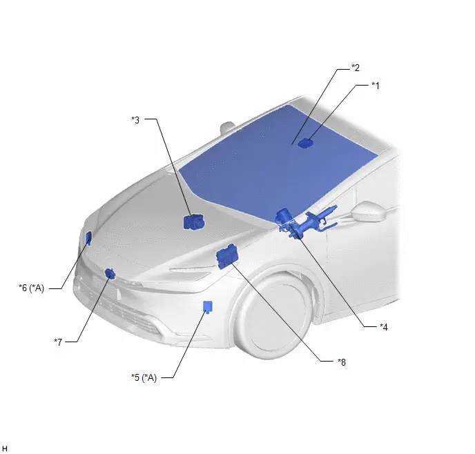
|
*A |
w/ Front Cross Traffic Alert |
- |
- |
|
*1 |
FORWARD RECOGNITION CAMERA |
*2 |
WINDSHIELD GLASS (HEATER) |
|
*3 |
NO. 2 SKID CONTROL ECU (BRAKE ACTUATOR ASSEMBLY) |
*4 |
POWER STEERING ECU ASSEMBLY |
|
*5 |
FRONT SIDE RADAR SENSOR (A) |
*6 |
FRONT SIDE RADAR SENSOR (B) |
|
*7 |
MILLIMETER WAVE RADAR SENSOR ASSEMBLY |
*8 |
ECM |
ILLUSTRATION
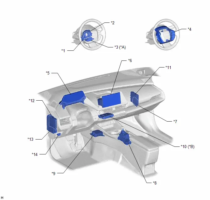
|
*A |
w/ Front Cross Traffic Alert |
*B |
w/ Telematics Transceiver |
|
*1 |
STEERING SENSOR |
*2 |
SPIRAL CABLE SUB-ASSEMBLY |
|
*3 |
MULTIPLEX NETWORK STEERING ECU (TOUCH SENSOR) |
*4 |
STEERING PAD SWITCH ASSEMBLY |
|
*5 |
COMBINATION METER ASSEMBLY |
*6 |
RADIO AND DISPLAY RECEIVER ASSEMBLY |
|
*7 |
CLEARANCE WARNING ECU ASSEMBLY |
*8 |
TRANSMISSION FLOOR SHIFT ASSEMBLY |
|
*9 |
AIRBAG ECU ASSEMBLY |
*10 |
TELEMATICS TRANSCEIVER |
|
*11 |
HYBRID Toyota Prius Vehicle CONTROL ECU |
*12 |
MAIN BODY ECU (MULTIPLEX NETWORK BODY ECU) |
|
*13 |
POWER DISTRIBUTION BOX ASSEMBLY - ECU-IGR NO. 3 FUSE |
*14 |
DLC3 |
ILLUSTRATION
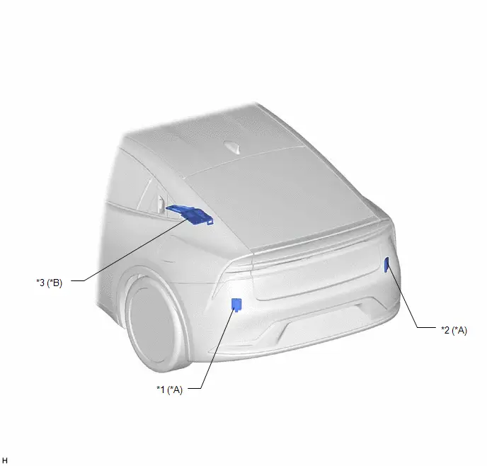
|
*A |
w/ Blind Spot Monitor System |
*B |
w/ Advanced Park |
|
*1 |
BLIND SPOT MONITOR SENSOR LH (B) |
*2 |
BLIND SPOT MONITOR SENSOR RH (A) |
|
*3 |
PARKING ASSIST ECU |
- |
- |
System Diagram
SYSTEM DIAGRAM
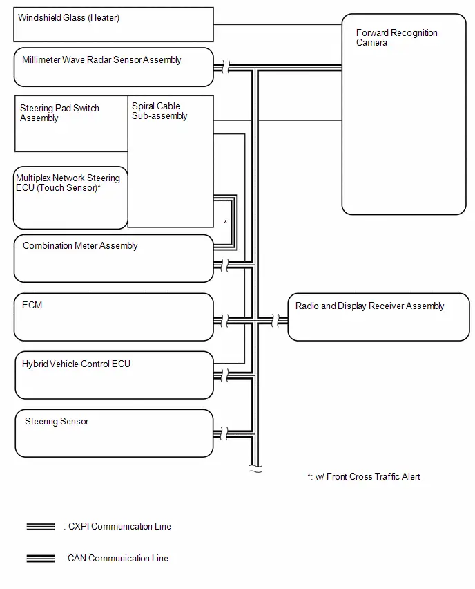
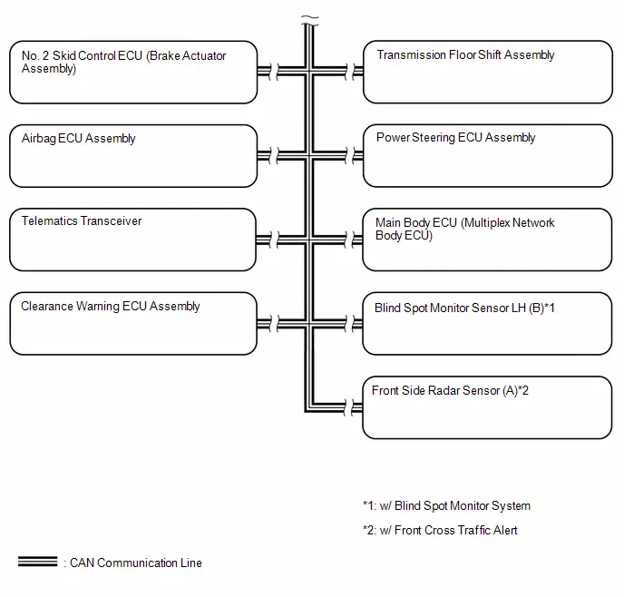
Local BUS Circuit
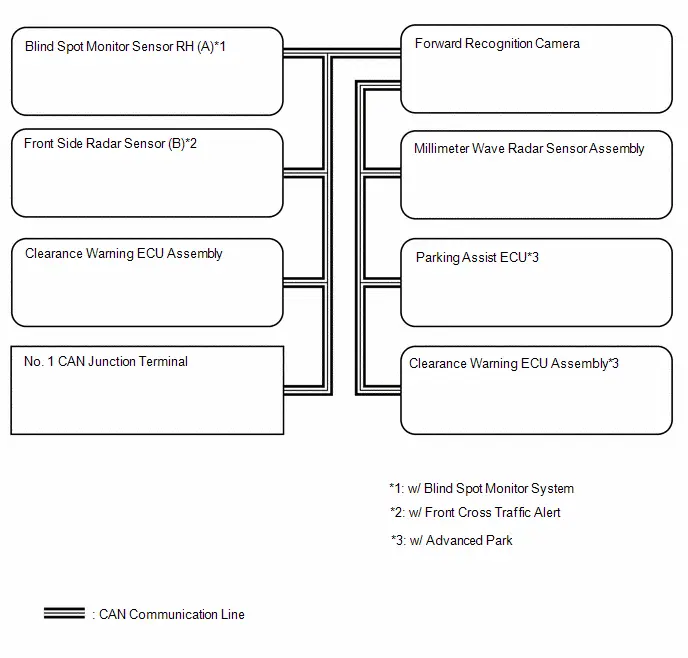
How To Proceed With Troubleshooting
CAUTION / NOTICE / HINT
HINT:
- Use the following procedure to troubleshoot the front camera system.
- *: Use the GTS.
PROCEDURE
|
1. |
Toyota Prius Vehicle BROUGHT TO WORKSHOP |
|

|
2. |
CUSTOMER PROBLEM ANALYSIS |
HINT:
- In troubleshooting, confirm that the problem symptoms have been accurately identified. Preconceptions should be discarded in order to make an accurate judgment. To clearly understand what the problem symptoms are, it is extremely important to ask the customer about the problem and the conditions at the time the malfunction occurred.
- Gather as much information as possible for reference. Past problems that seem unrelated may also help in some cases.
- The following 5 items are important points for problem analysis:
What
Toyota Prius Vehicle model, system name
When
Date, time, occurrence frequency
Where
Road conditions
Under what conditions?
Driving conditions, weather conditions
How did it happen?
Problem symptoms
|

|
3. |
PRE-CHECK |
(a) Measure the auxiliary battery voltage with the ignition switch off.
Standard voltage:
11 to 14 V
HINT:
If the voltage is below 11 V, recharge or replace the auxiliary battery before proceeding to the next step.
(b) Check the fuses and relays.
(c) Check the connector connections and terminals to make sure that there are no abnormalities such as loose connections, deformation, etc.
|

|
4. |
CHECK COMMUNICATION FUNCTION OF CAN COMMUNICATION SYSTEM* |
(a) Using the GTS, check for CAN communication system DTCs.
Click here

|
Result |
Proceed to |
|---|---|
|
CAN DTCs are not output |
A |
|
CAN DTCs are output |
B |
| B |

|
GO TO CAN COMMUNICATION SYSTEM |
|

|
5. |
CHECK FOR DTC* |
(a) Using the GTS, check for DTCs.
Chassis > Front Recognition Camera > Trouble Codes(b) If a DTC is output, record the DTC.
|
Result |
Proceed to |
|---|---|
|
DTCs are not output |
A |
|
DTC C10001C, C10051C, C100A62, C1A7F49, C1A9346, C1A9447, C1A9500 or C1AA800 is output |
B |
|
DTC other than C10001C, C10051C, C100A62, C1A7F49, C1A9346, C1A9447, C1A9500 and C1AA800 is output |
C |
| B |

|
GO TO DIAGNOSTIC TROUBLE CODE CHART (C10001C, C10051C, C100A62, C1A7F49, C1A9346, C1A9447, C1A9500 or C1AA800) |
| C |

|
GO TO STEP 8 |
|

|
6. |
CHECK Toyota Prius Vehicle CONTROL HISTORY (RoB)* |
(a) Using the GTS, check for Vehicle Control History (RoB).
HINT:
Based on the customer interview results, narrow down the cause of the malfunction and check the related Vehicle Control History (RoB).
Chassis > Front Recognition Camera > Utility|
Tester Display |
|---|
|
Toyota Prius Vehicle Control History (RoB) |
(b) Make a note of the output Vehicle Control History (RoB).
|
Result |
Proceed to |
|---|---|
|
Toyota Prius Vehicle Control History (RoB) is not output |
A |
|
Vehicle Control History (RoB) is output |
B |
| B |

|
GO TO Toyota Prius Vehicle CONTROL HISTORY (RoB) |
|

|
7. |
PROBLEM SYMPTOMS TABLE |
(a) Refer to Problem Symptoms Table.
Click here

|
Result |
Proceed to |
|---|---|
|
Fault is not listed in Problem Symptoms Table |
A |
|
Fault is listed in Problem Symptoms Table |
B |
| A |

|
USE SIMULATION METHOD TO CHECK |
| B |

|
GO TO PROBLEM SYMPTOMS TABLE |
|
8. |
RECONFIRM DTC OUTPUT* |
(a) Using the GTS, clear the DTCs.
Chassis > Front Recognition Camera > Clear DTCs(b) Reproduce the Toyota Prius vehicle conditions that were present when the DTCs that were noted were stored.
HINT:
Refer to each corresponding DTC for details on the detection conditions.
Click here

(c) Using the GTS, check for DTCs.
Chassis > Front Recognition Camera > Trouble Codes|
Result |
Proceed to |
|---|---|
|
DTCs are not output |
A |
|
DTCs are output |
B |
| A |

|
GO TO STEP 6 |
| B |

|
GO TO DIAGNOSTIC TROUBLE CODE CHART |
Operation Check
OPERATION CHECK
|
*a |
Automatic High Beam Indicator Light on Combination Meter Assembly |
AUTOMATIC HIGH BEAM OPERATION CHECK
(a) When all of the following conditions are met, the automatic high beam becomes standby mode and the automatic high beam indicator light will turn on:
- Turn the ignition switch to ON.
- Turn the light control switch to the AUTO or head position.
- Turn the headlight dimmer switch assembly to the low beam position.
- Turn on the auto high beam switch.
- The low beam headlights are illuminated
NOTICE:
- If the forward recognition camera cannot correctly recognize the view ahead due to bad weather (dense fog, etc.) or if dirt, etc., is obstructing the windshield glass, although a warning message is displayed on the multi-information display, the automatic high beam indicator in the combination meter assembly may not illuminate and the automatic high beam system may not operate.*
- If operation of the forward recognition camera is temporarily suspended due to excessively high temperature, or automatic beam axis calibration is being performed due to an altered Toyota Prius vehicle posture caused by loading, etc., the automatic high beam system may not operate even if the automatic high beam indicator in the combination meter assembly is illuminated.
HINT:
*: If it is confirmed that the inside of the windshield glass is dirty, remove the forward recognition camera and hood and clean the inside of the windshield glass using glass cleaner. (Even though the forward recognition camera is removed and installed when cleaning, it is not necessary to perform an axis alignment.)
Click here 

(b) When all of the following conditions are met with the automatic high beam is in standby mode, the high beams automatically turn on after a short delay:
- The Toyota Prius vehicle speed is more than approximately 34 km/h (21 mph).
- The area in front of the vehicle is dark.
- There are no oncoming vehicles with headlights on.
- There are no preceding vehicles with taillights on.
- There are few streetlights along the street ahead.
NOTICE:
The low beams may not change to high beams due to illumination from city lighting, signals or billboards, or due to reflective surfaces, such as signs or signboards.
(c) When the high beams turned on by the automatic high beam, the automatic high beam turns off the high beams and turns to low beams when any of the following conditions are met:
- The Toyota Prius vehicle speed is less than approximately 27 km/h (17 mph).
- The level of ambient light is higher than a specified threshold.
- There are oncoming vehicles with headlights on.
- There are preceding vehicles with taillights on.
- Light from streetlights ahead is higher than a specified threshold.
NOTICE:
- Under the following conditions, the high beams may change to low beams.
- There is interference from other illumination, such as city lighting, signals or billboards, or reflective surfaces, such as signs or signboards
- There is interference from the fog lights of an oncoming Toyota Prius vehicle
- Under the following conditions, the high beams may not change to low
beams.
- Passing an oncoming vehicle on a curve
- Preceding or oncoming vehicle appears and disappears on a continuous curve
- Preceding or oncoming vehicle appears and disappears due to the median, roadside trees or other obstructions
- Another Toyota Prius vehicle cuts in front of the vehicle
(d) When any of the following conditions are met, the automatic high beam will be canceled and the indicator light will turn off:
- Turn the ignition switch off.
- The light control switch is turned to any position except the AUTO or head position.
- Turn the headlight dimmer switch assembly to the high beam position.
- The auto high beam switch is turned off.
- The low beam headlights are not illuminated
Customize Parameters
CUSTOMIZE PARAMETERS
CUSTOMIZE FRONT CAMERA SYSTEM
NOTICE:
- When the customer requests a change in a function, first make sure that the function can be customized.
- Be sure to make a note of the current settings before customizing.
- When troubleshooting a function, first make sure that the function is set to the default setting.
(a) Customizing with the GTS
(1) Select the setting by referring to the table below.
Front Recognition Camera|
Tester Display |
Description |
Default |
Setting |
ECU |
|---|---|---|---|---|
|
PCS Function ON/OFF State Stored |
Refer to the table below |
Not Stored |
$00:Not Stored,$01:Stored |
Forward recognition camera |
|
PCS Warning Timing State Stored 1 |
Refer to the table below |
Stored |
$00:Not Stored,$01:Stored |
Forward recognition camera |
|
PCS Warning Timing State Stored 2 |
Refer to the table below |
Stored |
$00:Not Stored,$01:Stored |
Forward recognition camera |
|
PCS Collision Avoidance Assist Function |
Function that enables or disables the PCS Collision Avoidance Assist Function*1 |
ON |
$00:OFF,$01:ON |
Forward recognition camera |
|
PCS Reminder Buzzer Sound |
Function that enables or disables the PCS Reminder Buzzer Sound*1 |
ON |
$00:OFF,$01:ON |
Forward recognition camera |
|
PCS Right Turn/Left Turn Warning Function |
Function that enables or disables the PCS Right Turn/Left Turn Warning Function*2 |
ON |
$00:OFF,$01:ON |
Forward recognition camera |
|
PCS Right Turn/Left Turn Warning Buzzer Sound |
Function that enables or disables the PCS Right Turn/Left Turn Warning Buzzer Sound*2 |
ON |
$00:OFF,$01:ON |
Forward recognition camera |
|
Mild Braking in Plus Support Mode |
Function that enables or disables the Mild Braking in Plus Support Mode*2 |
ON |
$00:OFF,$01:ON |
Forward recognition camera |
|
PCS Drive Monitor Early Warning Function |
Selects ON/OFF for the PCS alarm early-output function for driver monitor*2 |
ON |
$00:OFF,$01:ON |
Forward recognition camera |
|
FCTA Both Side Display |
Selects ON/OFF for the FCTA both sides display function*1 |
OFF |
$00:OFF,$01:ON |
Forward recognition camera |
|
2 actioned Service Command |
Ready status of the driving assistant system is selected with the ignition switch ON (IG) HINT:
|
Invalid |
$00:Invalid,$01:Valid |
Forward recognition camera |
|
ACC Auto Start Buzzer |
Selects ON/OFF for the auto start buzzer*2 |
Valid |
$00:Invalid,$01:Valid |
Forward recognition camera |
|
ACC Auto Start Front Gaze Resume Request Buzzer |
Selects ON/OFF for the forward looking return request buzzer for automatic departure*2 |
Valid |
$00:Invalid,$01:Valid |
Forward recognition camera |
|
AHB/AHS Performance Adjustment |
Function that selects the AHB/AHS Performance Adjustment setting*3 |
Normal |
$00:Normal,$01:Special Performance 1 |
Forward recognition camera |
- *1: w/ Front Cross Traffic Alert
- *2: Cannot be used
- *3: Make sure to check the customize setting item "AHB/AHS City Area
Constant" before customize settings.
When AHB/AHS City Area Constant is Pattern 1 or 2: By setting to "Special Performance 1", operations (changes to high beam, etc.) at places with bright surroundings such as a street will increase.
When AHB/AHS City Area Constant is Pattern 3: By setting to "Special Performance 1", operations (changes to high beam, etc.) at places with bright surroundings such as a street will decrease.
|
Customize Setting |
Description |
Setting |
|---|---|---|
|
PCS Function ON/OFF State Stored |
Function to maintain the pre-collision system on/off setting when the ignition switch is turned to ON from off. |
Not stored: Pre-collision system always turns on Stored: Pre-collision system maintains previous setting |
|
PCS Warning Timing State Stored 1 |
Function to set whether or not to store the warning sensitivity setting when the PCS function is turned from off to on while the ignition switch is ON. |
Not Stored: Sensitivity setting is reset to default Stored: Sensitivity settings are maintained as previous value |
|
PCS Warning Timing State Stored 2 |
Function to set whether or not to store the warning sensitivity setting when the PCS function is on and the ignition switch is turned from off to ON. |
Not Stored: Sensitivity setting is reset to default Stored: Sensitivity settings are maintained as previous value |
Initialization
INITIALIZATION
STEERING SENSOR ZERO POINT CALIBRATION
(a) Start the hybrid control system.
(b) Drive the vehicle straight ahead at 35 km/h (22 mph) or more for 5 seconds or more.
(c) Turn the ignition switch off.
Utility
UTILITY
Recognition Camera/Target Position Memory
HINT:
Recognition Camera/Target Position Memory is used to enter required information into the forward recognition camera.
(a) Perform Recognition Camera/Target Position Memory according to the display on the GTS.
Chassis > Front Recognition Camera > Utility|
Tester Display |
|---|
|
Recognition Camera/Target Position Memory |
HINT:
For forward recognition camera adjustment procedures.
Click here 
HINT:
Recognition Camera Axis Adjust is used to calibrate the internal data of the forward recognition camera to enhance its recognition accuracy.
Recognition Camera Axis Adjust
(a) Perform Recognition Camera Axis Adjust according to the display on the GTS.
Chassis > Front Recognition Camera > Utility|
Tester Display |
|---|
|
Recognition Camera Axis Adjust |
HINT:
For forward recognition camera adjustment procedures.
Click here 
HINT:
Perform this procedure to save the beam axis alignment values stored in the millimeter wave radar sensor assembly to the forward recognition camera.
Camera Axis Adjustment Value Write
(a) Camera Axis Adjustment Value Write according to the display on the GTS.
Chassis > Front Recognition Camera > Utility|
Tester Display |
|---|
|
Camera Axis Adjustment Value Write |
PCS Image Information Clear
HINT:
PCS Image Information Clear is used to clear the PCS Image Information data.
(a) Perform PCS Image Information Clear according to the display on the GTS.
Chassis > Front Recognition Camera > Utility|
Tester Display |
|---|
|
PCS Image Information Clear |
PCS Image Record Setting
HINT:
PCS Image Record Setting is used to activate/deactivate the PCS image recording function.
(a) Perform PCS Image Record Setting according to the display on the GTS.
Chassis > Front Recognition Camera > Utility|
Tester Display |
|---|
|
PCS Image Record Setting |
Initial Axis Adjust Value Display
HINT:
This utility is used to display the initial axis adjust value display stored in the forward recognition camera.
(a) Following the instructions on the GTS, perform "Initial Axis Adjust Value Display".
Chassis > Front Recognition Camera > Utility|
Tester Display |
|---|
|
Initial Axis Adjust Value Display |
Front Recognition Camera Axis Misalignment Reading
HINT:
This utility is used to check the front recognition camera axis misalignment reading calculated by the forward recognition camera.
(a) Following the instructions on the GTS, perform "Front Recognition Camera Axis Misalignment Reading".
Chassis > Front Recognition Camera > Utility|
Tester Display |
|---|
|
Front Recognition Camera Axis Misalignment Reading |
HINT:
This utility transitions to online axis alignment mode of the forward recognition camera.
Transition to Online Axis Alignment Mode
(a) Following the instructions on the GTS, perform "Transition to Online Axis Alignment Mode".
Chassis > Front Recognition Camera > Utility|
Tester Display |
|---|
|
Transition to Online Axis Alignment Mode |
Navigation Installation Information Initialization
HINT:
This utility is used to initialize the navigation installation information stored in the front recognition camera.
(a) Following the instructions on the GTS, perform "Navigation Installation Information Initialization".
Chassis > Front Recognition Camera > Utility|
Tester Display |
|---|
|
Navigation Installation Information Initialization |
Problem Symptoms Table
PROBLEM SYMPTOMS TABLE
HINT:
- If no DTC is output when a diagnosis code check is performed for the front camera system and the CAN communication system, perform diagnosis according to the following symptoms.
- Use the table below to help determine the cause of problem symptoms. If multiple suspected areas are listed, the potential causes of the symptoms are listed in order of probability in the "Suspected Area" column of the table. Check each symptom by checking the suspected areas in the order they are listed. Replace parts as necessary.
- Inspect the fuses and relays related to this system before inspecting the suspected areas below.
|
Symptom |
Suspected Area |
Link |
|---|---|---|
|
Driving assist switch, RES switch, - switch, CANCEL switch cannot be operated |
Steering pad switch circuit |
|
|
Hybrid Toyota Prius vehicle control ECU |
|
|
|
Driving assist mode select switch cannot be operated |
Steering pad switch circuit |
|
|
Toyota Prius Vehicle-to-vehicle distance switch cannot be operated |
Steering pad switch circuit |
|
|
LTA switch cannot be operated |
Steering pad switch circuit |
|


Terminals Of Ecu
TERMINALS OF ECU
NOTICE:
- DTCs may be output when connectors are disconnected during inspection. Therefore, be sure to clear the DTCs using the GTS once the inspection has been completed.
- Do not apply excessive force to the forward recognition camera connector.

CHECK FORWARD RECOGNITION CAMERA
(a) Measure the voltage and resistance according to the value(s) in the table below.
|
Terminal No. (Symbol) |
Terminal Description |
Condition |
Specified Condition |
|---|---|---|---|
|
U10-1 (CA2L) |
CAN communication signal |
- |
- |
|
U10-2 (CA2P) |
CAN communication signal |
- |
- |
|
U10-3 (CA3L) |
CAN communication signal |
- |
- |
|
U10-4 (CA3H) |
CAN communication signal |
- |
- |
|
U10-5 (LKSW) - U10-13 (GND) |
Driving assist mode select switch, LTA switch and Toyota Prius Vehicle-to-vehicle distance switch circuit |
Driving assist mode select switch, LTA switch and Vehicle-to-vehicle distance switch OFF |
10 kΩ or higher |
|
Driving assist mode select switch pushed |
Below 2.5 Ω |
||
|
LTA switch pushed |
114 to 126 Ω |
||
|
Toyota Prius Vehicle-to-vehicle distance switch pushed |
485 to 536 Ω |
||
|
U10-8 (HTR) - U10-7 (SGND) |
Camera heater circuit |
Ignition switch ON, heater operating |
11 to 14 V |
|
Ignition switch ON, heater not operating |
Below 1 V |
||
|
U10-9 (CA1N) |
CAN communication signal |
- |
- |
|
U10-10 (CA1P) |
CAN communication signal |
- |
- |
|
U10-11 (CANL) |
CAN communication signal |
- |
- |
|
U10-12 (CANH) |
CAN communication signal |
- |
- |
|
U10-16 (IGB) - U10-13 (GND) |
Power source (IG) |
Ignition switch ON |
11 to 14 V |
|
Ignition switch off |
Below 1 V |
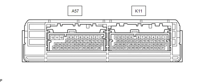
CHECK HYBRID Toyota Prius Vehicle CONTROL ECU
(a) Measure the resistance according to the value(s) in the table below.
|
Terminal No. (Symbols) |
Terminal Description |
Condition |
Specified Condition |
|---|---|---|---|
|
K11-29(CCS) - K11-43(CCSG) |
Driving assist switch, RES switch, - switch, CANCEL switch circuit |
Driving assist switch, RES switch, - switch, CANCEL switch OFF |
10 kΩ or higher |
|
Driving assist switch pushed |
Below 2.5 Ω |
||
|
CANCEL switch pushed |
228 to 252 Ω |
||
|
RES switch pushed |
599 to 661 Ω |
||
|
- switch pushed |
1463 to 1617 Ω |
Freeze Frame Data
FREEZE FRAME DATA
DESCRIPTION
(a) When a front camera system DTC is stored, the forward recognition camera stores the current vehicle (ECU or sensor) state as Freeze Frame Data.
CHECK FREEZE FRAME DATA
(a) Select a DTC to display the freeze frame data.
Chassis > Front Recognition Camera > Trouble Codes(b) Check the freeze frame data for the output DTC.
FREEZE FRAME DATA CHART
HINT:
Depending on the specifications of the Toyota Prius vehicle, etc., some items may not be displayed or may not be operable.
Chassis > Front Recognition Camera|
Tester Display |
Measurement Item |
Range |
Normal Condition |
Diagnostic Note |
|---|---|---|---|---|
|
Total Distance Traveled |
- |
- |
- |
Cannot be used |
|
Total Distance Traveled - Unit |
- |
- |
- |
Cannot be used |
|
Online Adjustment Progress Status |
Online axis adjustment progress of forward recognition camera |
0%, 10%, 20%, 40%, 60%, 80% or 100% |
The online axis adjustment progress is displayed. |
- |
|
Online Adjustment Normal Completion Flag |
Online axis adjustment status of forward recognition camera |
Not Normal Complete or Normal Complete |
The online axis adjustment status is displayed. |
- |
|
FOE Confirmation All Target Recognition Process Complete Flag |
Axis alignment (One Time Recognition) status of forward recognition camera |
Incomplete or Complete |
The axis alignment (One Time Recognition) status is displayed. |
- |
|
Confirmation FOE Origin X |
FOE coordinates X when forward recognition camera optical axis confirmation is being performed |
0 to 2896 pix |
- |
- |
|
Confirmation FOE Origin Y |
FOE coordinates Y when forward recognition camera optical axis confirmation is being performed |
0 to 1876 pix |
- |
- |
|
Confirmation Roll Angle |
Roll angle when forward recognition camera optical axis confirmation is being performed |
-5 to 5 deg |
- |
- |
|
FOE Origin X Gap |
Difference between initial FOE coordinates X and FOE coordinates X when forward recognition camera optical axis confirmation is being performed |
-5 to 5 deg |
- |
- |
|
FOE Origin Y Gap |
Difference between initial FOE coordinates Y and FOE coordinates Y when forward recognition camera optical axis confirmation is being performed |
-5 to 5 deg |
- |
- |
|
Roll Angle Gap |
Difference between initial roll angle and roll angle when forward recognition camera optical axis confirmation is being performed |
-5 to 5 deg |
- |
- |
|
Field FOE Origin X gap |
Difference between learned FOE coordinates X and FOE coordinates X when forward recognition camera optical axis confirmation is being performed |
-5 to 5 deg |
- |
- |
|
Field FOE Origin Y gap |
Difference between learned FOE coordinates Y and FOE coordinates Y when forward recognition camera optical axis confirmation is being performed |
-5 to 5 deg |
- |
- |
|
Field Roll Angle Gap |
Difference between learned roll angle and roll angle when forward recognition camera optical axis confirmation is being performed |
-5 to 5 deg |
- |
- |
|
IG Voltage |
IG voltage value |
0.00 to 21.31 V |
11 to 14V |
- |
|
Camera Temperature |
Temperature of forward recognition camera |
-128 to 127°C (-262 to 261°F) |
Temperature of forward recognition camera displayed |
- |
|
Buzzer (Line) Information |
Whether or not a buzzer is installed to the forward recognition camera |
Without Buzzer (Line) or With Buzzer (Line) |
Without Buzzer (Line): Not installed With Buzzer (Line): Installed |
- |
|
Camera Low Temperature Flag Counter |
Cumulative number of times forward recognition camera low temperature flag was set |
0 to 255 |
Current number of times forward recognition camera low temperature flag was set |
|
|
Camera High Temperature1 Flag Counter |
Cumulative number of times forward recognition camera high temperature flag 1 was set |
0 to 255 |
Current number of times forward recognition camera high temperature flag 1 was set |
|
|
Camera Low Voltage Flag Counter |
Cumulative number of times forward recognition camera was outside of the guaranteed operation voltage range (Toyota Prius vehicle control history (RoB) (low voltage)) |
0 to 255 |
Current number of times forward recognition camera was outside of the guaranteed operation voltage range (vehicle control history (RoB) (low voltage)) |
|
|
Camera High Voltage Flag Counter |
Cumulative number of times forward recognition camera was outside of the guaranteed operation voltage range (Toyota Prius vehicle control history (RoB) (high voltage)) |
0 to 255 |
Current number of times forward recognition camera was outside of the guaranteed operation voltage range (vehicle control history (RoB) (high voltage)) |
|
|
Axis Misalignment Cumulative Count |
Cumulative number of forward recognition camera axis misalignment |
0 to 255 |
Displays the cumulative number of forward recognition camera beam axis misalignments. |
If the number is 255 or more, 255 is displayed. |
|
Front Recognition Camera Not Adjusted Flag |
Status of forward recognition camera optical axis alignment |
OFF or ON |
OFF: Adjusted ON: Not adjusted |
- |
|
FOE Improper Flag |
FOE error when forward recognition camera optical axis alignment is being performed |
OFF or ON |
OFF: Normal ON: Abnormal |
- |
|
Targets Distance Improper Flag |
Target distance error when forward recognition camera optical axis alignment is being performed |
OFF or ON |
OFF: Normal ON: Abnormal |
- |
|
Targets Not Fixed Flag |
Target fixing error when forward recognition camera optical axis alignment is being performed |
OFF or ON |
OFF: Normal ON: Abnormal |
- |
|
Numbers of Targets Improper Flag |
Abnormal target number error when forward recognition camera optical axis alignment is being performed |
OFF or ON |
OFF: Normal ON: Abnormal |
- |
|
Relative Distance of Targets Improper Flag |
Target setting position error when forward recognition camera optical axis alignment is being performed |
OFF or ON |
OFF: Normal ON: Abnormal |
- |
|
Target 1 Improper Flag |
Target 1 error when forward recognition camera optical axis alignment is being performed |
OFF or ON |
OFF: Normal ON: Abnormal |
- |
|
Target 2 Improper Flag |
Target 2 error when forward recognition camera optical axis alignment is being performed |
OFF or ON |
OFF: Normal ON: Abnormal |
- |
|
Target 3 Improper Flag |
Target 3 error when forward recognition camera optical axis alignment is being performed |
OFF or ON |
OFF: Normal ON: Abnormal |
- |
|
Recognition Time Exceeded Flag |
Excessive recognition time error when forward recognition camera optical axis alignment is being performed |
OFF or ON |
OFF: Not exceeded ON: Exceeded |
- |
|
Improper Roll Angle Flag |
Roll angle error when forward recognition camera optical axis alignment is being performed |
OFF or ON |
OFF: Normal ON: Abnormal |
- |
|
Online Adjustment Toyota Prius Vehicle Speed Improper Flag |
Excessive vehicle speed error when forward recognition camera driving axis alignment is being performed |
OFF or ON |
OFF: Not exceeded ON: Exceeded |
- |
|
Online Adjustment Camera Blockage Flag |
Camera dirty state when forward recognition camera driving axis alignment is being performed |
OFF or ON |
OFF: Not dirty ON: Dirty |
- |
|
Online Adjustment Impossible Flag |
Recognition invalid state when forward recognition camera driving axis alignment is being performed |
OFF or ON |
OFF: Recognition valid ON: Recognition invalid |
- |
|
Online Adjustment FOE Improper Flag |
Outside of FOE range error when forward recognition camera driving axis alignment is being performed |
OFF or ON |
OFF: Normal ON: Abnormal |
- |
|
Online Adjustment FOE Writing Incomplete Flag |
FOE writing error when forward recognition camera driving axis alignment is being performed |
OFF or ON |
OFF: Normal ON: Abnormal |
- |
|
Online Adjustment Bad Condition Flag |
Bad environment state when forward recognition camera driving axis alignment is being performed |
OFF or ON |
OFF: Environment not bad ON: Environment bad |
- |
|
Camera Low Voltage Flag |
Excessive low voltage status of forward recognition camera |
OFF or ON |
OFF: Low voltage not detected ON: Low voltage detected |
If this item indicates "ON", the camera might be temporarily unavailable. |
|
Camera High Voltage Flag |
Excessive high voltage status of forward recognition camera |
OFF or ON |
OFF: High voltage not detected ON: High voltage detected |
If this item indicates "ON", the camera might be temporarily unavailable. |
|
Camera Low Temperature Flag |
Excessive low temperature status of forward recognition camera |
OFF or ON |
OFF: Excessive low temperature not detected (approximately -30°C (-22°F) or more) ON: Excessive low temperature detected (approximately -30°C (-22°F) or less) |
|
|
Camera High Temperature 1 Flag |
Excessive low temperature status of forward recognition camera |
OFF or ON |
OFF: Excessive high temperature not detected (approximately 80°C (176°F) or less) ON: Excessive high temperature detected (approximately 80°C (176°F) or more) |
|
|
Camera Optical Axis Misalignment Flag (X ) |
Forward recognition camera beam axis misalignment (horizontal/left direction) |
OFF or ON |
OFF: Camera not misaligned in X direction ON: Camera misaligned in X direction |
- |
|
Camera Optical Axis Misalignment Flag (X-) |
Forward recognition camera beam axis misalignment (horizontal/right direction) |
OFF or ON |
OFF: Camera not misaligned in X- direction ON: Camera misaligned in X- direction |
- |
|
Camera Optical Axis Misalignment Flag (Y ) |
Forward recognition camera beam axis misalignment (vertical/down direction) |
OFF or ON |
OFF: Camera not misaligned in Y direction ON: Camera misaligned in Y direction |
- |
|
Camera Optical Axis Misalignment Flag (Y-) |
Forward recognition camera beam axis misalignment (vertical/up direction) |
OFF or ON |
OFF: Camera not misaligned in Y- direction ON: Camera misaligned in Y- direction |
- |
|
Camera Roll Angle Misalignment Flag |
Forward recognition camera beam axis misalignment (roll direction) |
OFF or ON |
OFF: Camera not misaligned in roll direction ON: Camera misaligned in roll direction |
- |
|
ECU Security Key Registered Incomplete Flag |
Security key unregistered status of forward recognition camera ECU |
OFF, ON or Not Fixed |
Current security key registration status of ECU |
- |
|
Camera Low Visibility Flag |
Low visibility of the forward recognition camera |
No Low Visibility or Under Low Visibility |
The current visibility is displayed |
- |
|
Blockage Condition Visibility Level |
Blockage condition recognized by the forward recognition camera |
Level0, Level1, Level2, Level3, Level4, Level5, Level6, Level7 or Level8 |
The blockage condition is displayed. |
- |
|
Fogged Condition Visibility Level |
Fogged condition recognized by the forward recognition camera |
Level0, Level1, Level2, Level3, Level4, Level5, Level6, Level7 or Level8 |
The fogged condition is displayed. |
- |
|
Bad Weather Condition Visibility Level |
Bad weather condition recognized by the forward recognition camera |
Level0, Level1, Level2, Level3, Level4, Level5, Level6, Level7 or Level8 |
The bad weather condition is displayed. |
- |
|
Heater Available Flag |
Whether a hot-wire heater exists or not |
Heater Absent or Heater Present |
Heater Absent: w/o Heater Wire Heater Present: w/ Heater Wire |
If this item is Heater Absent, a new forward recognition camera with an open in the heater wire circuit may be installed. |
|
Heater Control Allow Flag |
Whether heater wire control allowed or not |
Not Allowed or Allowed |
Not Allowed: Heater wire control not allowed Allowed: Heater wire control allowed |
If this item is Not Allowed, following conditions are expected.
|
|
Heater During Control Flag |
Heater wire control status |
Not Controlled or In Control |
Not Controlled: Heater wire not operating In Control: Heater wire operating |
This item becomes In Control when Heater Control Allow Flag is Allowed, ambient temperature is 10°C (50°F) or less and area front of forward recognition camera is fogged. (w/ heated windshield defroster: While heated windshield defroster is operating, this item remains Not Controlled) |
|
IGP |
IG status |
IG-P OFF or IG-P ON |
IG-P OFF: IG OFF IG-P ON: IG ON |
- |
|
IGP Flank |
IG status |
Out of IGP-ON -> OFF or IGP-ON -> OFF |
IGP-ON -> OFF |
- |
|
PCS Installation Availability |
Whether pre-collision system installed or not |
Not Installed or Installed |
Not Installed: PCS not installed Installed: PCS installed |
- |
|
FCTA Installation Availability |
Whether front cross traffic alert installed or not |
Not Installed or Installed |
Not Installed: FCTA not installed Installed: FCTA installed |
- |
|
ACC Installation Availability |
Whether dynamic radar cruise control installed or not |
Not Installed or Installed |
Not Installed: ACC not installed Installed: ACC installed |
- |
|
CCS Installation Availability |
Whether cruise control installed or not |
Not Installed or Installed |
Not Installed: CCS not installed Installed: CCS installed |
- |
|
LDA Installation Availability |
Whether lane departure alert installed or not |
Not Installed or Installed |
Not Installed: LDA not installed Installed: LDA installed |
- |
|
LTA Installation Availability |
Whether lane trace assist installed or not |
Not Installed or Installed |
Not Installed: LTA not installed Installed: LTA installed |
- |
|
LCA Installation Availability |
Whether lane change assist installed or not |
Not Installed or Installed |
Not Installed: LCA not installed Installed: LCA installed |
- |
|
AHB Installation Availability |
Whether automatic high beam installed or not |
Not Installed or Installed |
Not Installed: AHB not installed Installed: AHB installed |
- |
|
RSA Installation Availability |
Whether road sign assist installed or not |
Not Installed or Installed |
Not Installed: RSA not installed Installed: RSA installed |
- |
|
TMN Installation Availability |
Whether TMN installed or not |
Not Installed or Installed |
Not Installed: TMN not installed Installed: TMN installed |
- |
|
PDA Installation Availability |
Whether proactive driving assist installed or not |
Not Installed or Installed |
Not Installed: PDA not installed Installed: PDA installed |
- |
|
ISA Installation Availability |
Whether speed limiter system installed or not |
Not Installed or Installed |
Not Installed: ISA not installed Installed: ISA installed |
- |
|
DESA Installation Availability |
Whether emergency driving stop system installed or not |
Not Installed or Installed |
Not Installed: DESA not installed Installed: DESA installed |
- |
|
Estimate Toyota Prius Vehicle Acceleration |
Estimated vehicle acceleration value |
-32.768 to 32.767 m/s2 |
- |
- |
|
Estimated Toyota Prius Vehicle Acceleration Condition |
Estimated vehicle acceleration condition |
Not Fixed, Valid, Invalid or Error |
- |
- |
|
Mediation Result Longitudinal ID Value |
Mediation result longitudinal ID value |
0 to 63 |
- |
- |
|
Steering Wheel Information |
Steering wheel information |
Unused, Left, Right or Default Value |
Steering wheel installation location |
- |
|
2WD/4WD Information |
Toyota Prius Vehicle drive information |
2WD, 4WD or Default Value |
The vehicle drive information is displayed |
- |
|
Powertrain Information |
Powertrain information |
Conventional, SS, HV, PHV, EV, 1MHV, FCV or Default Value |
Conventional: Conventional Toyota Prius vehicle SS: w/ Stop and start vehicle HV: Hybrid vehicle PHV: PHV vehicle EV: EV vehicle 1MHV: 1MHV vehicle FCV: FCV vehicle Default Value: Vehicle information not confirmed |
- |
|
Transmission Information |
Transmission information |
MT, AT, CVT, MMT, SMT, AT for HV or Default Value |
The transmission type is displayed |
- |
|
Estimated Speed Unit |
Toyota Prius Vehicle speed unit |
Unconfirmed, unit is kph or unit is mph |
- |
- |
|
Estimated Driving Side |
Driving side |
Unconfirmed, Right-hand driving estimated or Left-hand driving estimated |
- |
- |
|
RSA Equipped |
Road sign assist function availability |
Not Equipped or Equipped |
Not Equipped: Road sign assist function not equipped Equipped: Road sign assist function equipped |
- |
|
Navigation Fusion Equipped |
Road sign assist navigation fusion function availability |
Not Equipped or Equipped |
Not Equipped: Road sign assist navigation fusion function not equipped Equipped: Road sign assist navigation fusion function equipped |
- |
|
GNSS Location Information Validation |
GNSS location information |
Invalid or Valid |
- |
- |
|
LDA Customize Condition Flag |
Lane departure alert customize condition |
OFF or ON |
Customize setting displayed |
- |
|
LDA Control Condition |
Lane departure alert control condition |
LDA Enabled or LDA Disabled |
LDA Enabled |
- |
|
LTA Switch Condition Flag |
ON/OFF status of LTA switch |
OFF or ON |
ON/OFF status of LTA switch |
- |
|
LTA Control Condition |
Lane tracing assist control condition |
LTA Enabled or LTA Disabled |
LTA Enabled |
- |
|
Hands-Off Customize Condition Flag |
Advanced drive control condition |
OFF or ON |
Customize setting displayed |
Cannot be used |
|
Hands-Off Control Condition |
Advanced drive control status |
Hands-Off Enabled or Hands-Off Disabled |
Customize setting displayed |
Cannot be used |
|
LCA Customize Condition Flag |
Lane change assist customize condition |
OFF or ON |
Customize setting displayed |
- |
|
LCA Control Condition |
Lane change assist control condition |
LCA Enabled or LCA Disables |
LCA Enabled |
- |
|
PCS Alarm Sensitivity Output Signal |
Pre-collision system alarm sensitivity |
Not Displayed, Fast, Standard or Slow |
Customize setting displayed |
- |
|
PCS Switch OFF Condition Output Signal |
Pre-collision system ON/OFF status |
Function ON or Function OFF |
Function ON: Pre-collision system ON Function OFF: Pre-collision system OFF |
- |
|
CTA Switch OFF Condition Output Signal |
Front cross traffic alert ON/OFF status |
Function ON or Function OFF |
Function ON: Front cross traffic alert function ON Function OFF: Front cross traffic alert function OFF |
- |
|
PCS Availability Flag Output Signal |
Pre-collision system availability |
Enabled or Disabled |
Enabled |
- |
|
PCS Right Turn/Left Turn Warning Switch OFF Status |
PCS right turn/left turn warning function ON/OFF status |
Function ON or Function OFF |
Function ON: PCS right turn/left turn warning function ON Function OFF: PCS right turn/left turn warning function OFF |
- |
|
PCS PBA Invalid Flag |
Pre-collision brake assist function status |
OFF or ON |
OFF: Pre-collision brake assist function valid ON: Pre-collision brake assist function invalid |
- |
|
PCS PCW Invalid Flag |
PCS warning buzzer function status |
OFF or ON |
OFF: PCS warning buzzer function valid ON: PCS warning buzzer function invalid |
- |
|
PCS PB Invalid Flag |
Pre-collision brake function status |
OFF or ON |
OFF: Pre-collision brake function valid ON: Pre-collision brake function invalid |
- |
|
PCS ESA Invalid Flag |
Emergency steering assist function status |
OFF or ON |
OFF: Emergency steering assist function valid ON: Emergency steering assist function invalid |
- |
|
PCS AES Invalid Flag |
Active steering assist function status |
OFF or ON |
OFF: Active steering assist function valid ON: Active steering assist function invalid |
- |
|
FCTA Invalid Flag |
Front cross traffic alert function status |
OFF or ON |
OFF: Front cross traffic alert function valid ON: Front cross traffic alert function invalid |
- |
|
PCS PAS A Invalid Flag |
Acceleration suppression at low speed (A control) invalid status |
OFF or ON |
OFF: Acceleration suppression at low speed (A control) function valid ON: Acceleration suppression at low speed (A control) function invalid |
- |
|
PCS PKSB Coordination Invalid Flag |
PCS PKSB coordination function status |
OFF or ON |
OFF: PCS PKSB coordination function status valid ON: PCS PKSB coordination function status invalid |
- |
|
PCS Indicator Display Output Signal |
Indicator status of the pre-collision system function |
OFF, Lighting, Blinking (Slow) or Blinking (Fast) |
- |
- |
|
CTA Alarm Sensitivity Output Signal |
Front cross traffic alert function sensitivity status |
Not Displayed, Fast, Standard or Slow |
Customize setting displayed |
- |
|
PCS Alarm Sensitivity (For User1 Storing) Output |
PCS warning sensitivity |
Not Displayed, Quick, Standard or Slow |
Customize setting displayed |
- |
|
PCS Alarm Sensitivity (For User2 Storing) Output |
PCS warning sensitivity |
Not Displayed, Quick, Standard or Slow |
Customize setting displayed |
- |
|
PCS Alarm Sensitivity (For User3 Storing) Output |
PCS warning sensitivity |
Not Displayed, Quick, Standard or Slow |
Customize setting displayed |
- |
|
PCS Alarm Sensitivity (For Guest Storing) Output |
PCS warning sensitivity |
Not Displayed, Quick, Standard or Slow |
Customize setting displayed |
- |
|
CTA Alarm Sensitivity (For User1 Storing) Output |
Front cross traffic warning sensitivity |
Not Displayed, Quick, Standard or Slow |
Customize setting displayed |
- |
|
CTA Alarm Sensitivity (For User2 Storing) Output |
Front cross traffic warning sensitivity |
Not Displayed, Quick, Standard or Slow |
Customize setting displayed |
- |
|
CTA Alarm Sensitivity (For User3 Storing) Output |
Front cross traffic warning sensitivity |
Not Displayed, Quick, Standard or Slow |
Customize setting displayed |
- |
|
CTA Alarm Sensitivity (For Guest Storing) Output |
Front cross traffic warning sensitivity |
Not Displayed, Quick, Standard or Slow |
Customize setting displayed |
- |
|
PCS Alarm Sensitivity (For Plus Support) Output Signal |
PCS warning sensitivity |
Not Displayed, Quick, Standard or Slow |
Customize setting displayed |
Cannot be used |
|
CTA Alarm Sensitivity (For Plus Support) Output Signal |
Front cross traffic warning sensitivity |
Not Displayed, Quick, Standard or Slow |
Customize setting displayed |
Cannot be used |
|
Right Turn/Left Turn Warning Switch (Driver1) |
Right turn/left turn warning function ON/OFF status |
Function ON or Function OFF |
Function ON: Right turn/left turn warning function ON Function OFF: Right turn/left turn warning function OFF |
- |
|
Right Turn/Left Turn Warning Switch (Driver2) |
Right turn/left turn warning function ON/OFF status |
Function ON or Function OFF |
Function ON: Right turn/left turn warning function ON Function OFF: Right turn/left turn warning function OFF |
- |
|
Right Turn/Left Turn Warning Switch (Driver3) |
Right turn/left turn warning function ON/OFF status |
Function ON or Function OFF |
Function ON: Right turn/left turn warning function ON Function OFF: Right turn/left turn warning function OFF |
- |
|
Right Turn/Left Turn Warning Switch (Guest) |
Right turn/left turn warning function ON/OFF status |
Function ON or Function OFF |
Function ON: Right turn/left turn warning function ON Function OFF: Right turn/left turn warning function OFF |
- |
|
Right Turn/Left Turn Warning Switch (Plus Support) |
Right turn/left turn warning function ON/OFF status |
Function ON or Function OFF |
Function ON: Right turn/left turn warning function ON Function OFF: Right turn/left turn warning function OFF |
Cannot be used |
|
Current Toyota Prius Vehicle Speed |
Current vehicle speed |
0 to 255 km/h (0 to 158 mph) |
Current vehicle speed |
- |
|
Memory Toyota Prius Vehicle Speed |
Cruise control set speed |
0 to 255 km/h (0 to 158 mph) |
Cruise control set speed |
- |
|
Control Mode |
Cruise control mode status |
Toyota Prius Vehicle-to-vehicle Distance Control (All Speed), Vehicle-to-vehicle Distance Control (Hi Speed) or Constant Speed Control |
Vehicle-to-vehicle Distance Control (All Speed): Vehicle-to-vehicle distance control (all Speed) mode Vehicle-to-vehicle Distance Control (Hi Speed): Toyota Prius Vehicle-to-vehicle distance control (hi speed) mode Constant Speed Control: Constant speed control mode |
- |
|
Cruise Control Permission Flag |
Cruise control permission status |
Cruise Control Not Allowed or Cruise Control Allowed |
Cruise Control Not Allowed: Cruise control not allowed Cruise Control Allowed: Cruise control allowed |
- |
|
Main Switch Recognition Flag |
Cruise control main switch status |
OFF or ON |
OFF: Cruise control main switch OFF ON: Cruise control main switch ON |
- |
|
Set Cancel Switch Condition |
Set cancel switch operation condition |
No Operation or Operation Exists |
No Operation: Set cancel switch not operated Operation Exists: Set cancel switch operated |
- |
|
Resume Switch Condition |
RES switch operation condition |
No Operation or Operation Exists |
No Operation: RES switch not operated Operation Exists: RES switch operated |
- |
|
Up Switch |
switch operation condition |
No Operation or Operation Exists |
No Operation: switch not operated Operation Exists: switch operated |
- |
|
Down Switch |
- switch operation condition |
No Operation or Operation Exists |
No Operation: - switch not operated Operation Exists: - switch operated |
- |
|
Cancellation Switch Condition |
CANCEL switch operation condition |
No Operation or Operation Exists |
No Operation: CANCEL switch not operated Operation Exists: CANCEL switch operated |
- |
|
ACC Not Available Icon Lighting Request Flag |
Cruise control indicator status |
OFF or ON |
OFF: Off ON: On |
- |
|
Forward Toyota Prius Vehicle Lateral Position |
Lateral position of the vehicle ahead |
-40.96 to 40.92 m |
- |
When the vehicle is not detected, the maximum value is displayed. |
|
Forward Toyota Prius Vehicle Distance |
Distance to preceding vehicle |
0.00 to 327.64 m |
- |
When the vehicle is not detected, the maximum value is displayed. |
|
Forward Toyota Prius Vehicle Relative Speed |
Relative speed against preceding vehicle |
-51.200 to 51.75 m/s |
- |
When the vehicle is not detected, 0 is displayed. |
|
Set Toyota Prius Vehicle Interval Time |
Set distance to preceding vehicle for vehicle-to-vehicle distance control |
Set Vehicle Interval Time4, Set Vehicle Interval Time3, Set Vehicle Interval Time2 or Set Vehicle Interval Time1 |
Set Toyota Prius Vehicle Interval Time4: Short Set Vehicle Interval Time3: Middle (short) Set Vehicle Interval Time2: Middle (long) Set Vehicle Interval Time1: Long |
- |
|
ACC Control in Operation Flag |
Radar cruise control operation status |
Cruise Control Not in Operation or Cruise Control in Operation |
Cruise Control Not in Operation: Radar cruise control not operating Cruise Control in Operation: Radar cruise control operating |
- |
|
Acceleration Override |
Acceleration pedal operation while cruise control |
OFF or ON |
OFF: Acceleration override OFF ON: Acceleration override ON |
- |
|
ACC Brake Control in Operation |
Radar cruise control brake operation |
ACC Brake Control in Operation or No ACC Brake Control Operation |
ACC Brake Control in Operation: Brake operated No ACC Brake Control Operation: Brake not operated |
- |
|
Brake ON Flag |
Brake operation status |
OFF or ON |
OFF: Brake operation OFF ON: Brake operation ON |
- |
|
PDA Sensitivity Condition |
Proactive driving assist sensitivity |
Not Fixed, Fast, Normal or Late |
Customize setting displayed |
- |
|
PDA Function ON/OFF Condition |
Proactive driving assist operation |
OFF or ON |
OFF: Proactive driving assist OFF ON: Proactive driving assist ON |
- |
|
PDA (OAA) Function ON/OFF State |
Displays the status of the proactive driving assist (OAA) function |
OFF or ON |
OFF: Proactive driving assist (OAA) OFF ON: Proactive driving assist (OAA) ON |
- |
|
PDA (OAA) Installation Availability |
Displays whether the Toyota Prius vehicle is equipped with the proactive driving assist (OAA) function |
Not Equipped or Equipped |
Not Equipped: Vehicle not equipped with function Equipped: Vehicle equipped with function |
- |
|
PDA Not Available Flag |
Proactive driving assist availability |
Available or Not Available |
Available: Proactive driving assist function valid Not Available: Proactive driving assist function invalid |
- |
|
PDA (OAA) Not Available (Diagnosis) Flag |
Proactive driving assist (OAA) availability |
Available or Not Available |
Available: Proactive driving assist (OAA) function valid Not Available: Proactive driving assist (OAA) function invalid |
- |
|
PDA (DA) ON/OFF Status |
Displays the status of the proactive driving assist (DA) function |
OFF or ON |
OFF: Proactive driving assist (DA) OFF ON: Proactive driving assist (DA) ON |
- |
|
ISA Main Switch Recognition Flag Input Value |
Mode switch input value |
OFF or ON |
OFF: Other than speed limiter selected ON: Speed limiter selected |
- |
|
Set Cancellation Switch for Output |
Driving assist switch operation status |
OFF or ON |
OFF: Driving assist switch not operated ON: Driving assist switch operated |
- |
|
Cancellation Switch for Output |
CANCEL switch operation status |
OFF or ON |
OFF: CANCEL switch not operated ON: CANCEL switch operated |
- |
|
Resume Switch for Output |
RES switch operation status |
OFF or ON |
OFF: RES switch not operated ON: RES switch operated |
- |
|
Up Switch for Output |
switch operation status |
OFF or ON |
OFF: switch not operated ON: switch operated |
- |
|
Down Switch for Output |
- switch operation status |
OFF or ON |
OFF: - switch not operated ON: - switch operated |
- |
|
Kick Down Switch for Output |
Kick down switch operation status |
OFF or ON |
OFF: Kick down switch not operated ON: Kick down switch operated |
- |
|
Clutch Switch for Output |
Clutch switch operation status |
OFF or ON |
OFF: Clutch switch not operated ON: Clutch switch operated |
- |
|
ASL Main Switch Flag for Output |
Speed limiter system ON/OFF status |
OFF or ON |
OFF: ASL main switch not operated ON: ASL main switch operated |
- |
|
ISA in Control Flag |
Speed limiter system operation status |
Not in Operation or In Operation |
Not in Operation: Speed limiter system not operating In Operation: Speed limiter system operating |
- |
|
ISA Control Flag for Output |
Speed limiter request status |
OFF or ON |
OFF: Speed limiter not requested ON: Speed limiter requested |
- |
|
ISA Limit Applied Flag |
Speed limiter system ON/OFF status |
OFF or ON |
OFF: Speed limiter system OFF ON: Speed limiter system ON |
- |
|
ISA Requesting Vertical ID (Upper Limit) |
Speed limiter system request status |
No Request or Driver Operation |
Speed limiter system request status |
- |
|
ISA Requesting Toyota Prius Vehicle Speed (Upper Limit) |
Speed limiter system request vehicle speed |
0 to 255 km/h (0 to 158 mph) |
Speed limiter system request vehicle speed |
- |
|
ISA Request Acceleration (Upper Limit) (Variation No Limit) |
Speed limiter system request acceleration |
-32.768 to 32.767 m/s2 |
Speed limiter system request acceleration |
- |
|
ISA Braking Force and Driving Force Allocation Method Specification (Upper Limit) |
Speed limiter system driving force allocation |
Engine Only, Engine and Brake 1, Engine and Brake 2 or Brake Only |
Speed limiter system driving force allocation |
- |
|
ISA Speed Change Priority Request (Upper Limit) |
Speed limiter system shift control priority status |
No Brake Coordination Down Shifting Request or Brake Coordination Down Shifting Request Exists |
Speed limiter system shift control priority status |
- |
|
ISA Responsiveness Request (Upper Limit) |
Speed limiter system feedback status |
No FB, FB Control High Gain, FB Control Medium Gain or FB Control Low Gain |
Speed limiter system feedback status |
- |
|
ISA Brake Hold Control Prohibited Flag (Upper Limit) |
Speed limiter system brake hold prohibition status |
Allowed or Not Allowed |
Allowed: Speed limiter system brake hold control allowed Allowed: Speed limiter system brake hold control allowed |
- |
|
ISA Stop Control Permission Flag (Upper Limit) |
Speed limiter release permission status |
Not Allowed or Allowed |
Not Allowed: Speed limiter release allowed Allowed: Speed limiter release not allowed |
- |
|
ISA Brake Usage Limit Permission Flag (Upper Limit) |
Speed limiter system brake usage permission status |
Not Allowed or Allowed |
Not Allowed: Speed limiter system brake usage not allowed Allowed: Speed limiter system brake usage allowed |
- |
|
Driver Acceleration for Output |
Acceleration value |
-12.8 to 12.7 m/s2 |
Current value is displayed |
- |
|
Acceleration Limit for Output |
Acceleration value |
-12.8 to 12.7 m/s2 |
Current value is displayed |
- |
|
Acceleration for Output |
Acceleration value |
-12.8 to 12.7 m/s2 |
Current value is displayed |
- |
|
ISA Memory Limit Toyota Prius Vehicle Speed for Output |
Set vehicle speed |
0 to 255 km/h (0 to 158 mph) |
Current value is displayed |
- |
|
ISA Current Toyota Prius Vehicle Speed for Output |
ISA current vehicle speed |
0 to 255 km/h (0 to 158 mph) |
Current value is displayed |
- |
|
RSA Limit Toyota Prius Vehicle Speed for Output |
RSA limit vehicle speed |
0 to 255 km/h (0 to 158 mph) |
Current value is displayed |
- |
|
Shift Position |
Shift position |
0 to 255 |
- |
- |
|
Fail-Safe Factor B1a |
Cumulative number of speed limiter system fail-safe operation |
0 to 255 |
If this item is counted, fail-safe operation may have been performed |
- |
|
Fail-Safe Factor B1b |
Cumulative number of speed limiter system fail-safe operation |
0 to 255 |
If this item is counted, fail-safe operation may have been performed |
- |
|
Fail-Safe Factor B2 |
Cumulative number of speed limiter system fail-safe operation |
0 to 255 |
If this item is counted, fail-safe operation may have been performed |
- |
|
Fail-Safe Factor C1 |
Cumulative number of speed limiter system fail-safe operation |
0 to 255 |
If this item is counted, fail-safe operation may have been performed |
- |
|
Fail-Safe Factor C2 |
Cumulative number of speed limiter system fail-safe operation |
0 to 255 |
If this item is counted, fail-safe operation may have been performed |
- |
|
Fail-Safe Factor D1 |
Cumulative number of speed limiter system fail-safe operation |
0 to 255 |
If this item is counted, fail-safe operation may have been performed |
- |
|
Alert Timing Setting Information |
Alert timing setting information |
Early Timing or Normal Timing or Late Timing |
Customize setting displayed |
Cannot be used |
|
Forward Toyota Prius Vehicle Start Alert Switch |
Forward vehicle start alert ON/OFF status |
OFF or ON |
Customize setting displayed |
Cannot be used |
|
TMN (Signal) ON/OFF |
TMN (Signal) ON/OFF status |
OFF or ON |
Customize setting displayed |
Cannot be used |
|
PDA (SA) Customize Status |
Proactive driving assist customize status |
OFF or ON |
Customize setting displayed |
- |
|
PDA (SA) Control Status |
Proactive driving assist control status |
Enabled or Disabled |
Enabled |
- |
|
Export Used Toyota Prius Vehicle Mode |
Export used vehicle mode status |
OFF or ON |
Customize setting displayed |
- |
|
FCTA Both Side Display |
FCTA both side display function ON/OFF status |
OFF or ON |
OFF: FCTA both side display function OFF ON: FCTA both side display function ON |
The settings can be changed using the customize function using GTS. |
|
PCS Right Turn/Left Turn Warning Function |
PCS right turn/left turn warning function ON/OFF status |
OFF or ON |
OFF: PCS right turn/left turn warning function OFF ON: PCS right turn/left turn warning function ON |
Cannot be used |
|
PCS Right Turn/Left Turn Warning Buzzer Sound |
PCS right turn/left turn warning buzzer sound ON/OFF status |
OFF or ON |
OFF: PCS right turn/left turn warning buzzer sound OFF ON: PCS right turn/left turn warning buzzer sound ON |
Cannot be used |
|
Mild Braking in Plus Support Mode |
Mild braking in plus support mode ON/OFF status |
OFF or ON |
OFF: Mild braking in plus support mode OFF ON: Mild braking in plus support mode ON |
Cannot be used |
|
PCS Drive Monitor Early Warning Function |
PCS drive monitor early warning function ON/OFF status |
OFF or ON |
Customize setting displayed |
Cannot be used |
|
2 actioned Service Command |
2 actioned Service function status |
Invalid or Valid |
Invalid: Any of the driving assist system is ready with the ignition switch ON Valid: The driving assist system is not ready with the ignition switch ON (the driving assist system will be set to ready after the driving assist mode select switch is operated) |
The settings can be changed using the customize function using GTS. |
|
AHB/AHS Performance Adjustment |
Forward recognition camera sensitivity setting |
Normal or Special Performance 1 |
Customize setting displayed |
The settings can be changed using the customize function using GTS. |
Fail-safe Chart
FAIL-SAFE CHART
FAIL-SAFE FUNCTION
(a) If the system is malfunctioning, the telltale warning message is displayed on the multi-information display and the system is suspended in accordance with the malfunction.
Telltale Status List|
Indicator Status |
Conditions |
|---|---|
 |
The advanced driver assistance system is limited/disabled as a advanced driver assistance system related malfunction occurred |
 |
The pre-collision system is limited/disabled as a pre-collision system related malfunction occurred |
 |
The dynamic radar cruise control is limited/disabled as a dynamic radar cruise control related malfunction occurred |
 |
The cruise control is limited/disabled as a cruise control related malfunction occurred |
 |
The lane departure alert is limited/disabled as a lane departure alert related malfunction occurred |
 |
The lane tracing assist is limited/disabled as a lane tracing assist related malfunction occurred |
 |
The proactive driving assist is limited/disabled as a proactive driving assist related malfunction occurred |
|
Indicator Status |
Conditions |
|---|---|
 |
Pre-collision system related malfunctions or outages |
 |
Lane tracing assist related malfunction or function cancellation |
 |
Lane departure alert related malfunction or function cancellation |
 |
Lane change assist related malfunction or function cancellation*1 |
 |
Dynamic radar cruise control related malfunction or function cancellation |
 |
Cruise control related malfunction or function cancellation |
 |
Automatic high beam related malfunction or function cancellation |
 |
Road sign assist related malfunction or function cancellation*2 |
 |
Proactive driving assist related malfunction or function cancellation |
- *1: w/ Lane Change Assist
- *2: w/ Road Sign Assist
|
Warning Message |
Cause |
DTC/RoB No. |
Conditions to Return to Normal |
|---|---|---|---|
|
"System Malfunction Visit Your Dealer" |
Yaw Rate Sensor Malfunction |
X2000 |
After the malfunction is resolved, turn on the ignition switch again |
|
Steering Angle Sensor Malfunction |
X2001 |
||
|
Speed Sensor Malfunction |
X2004 |
||
|
Front Recognition Camera Optical Axis Not Adjusted |
X2014 |
||
|
Front Radar Sensor Destination Malfunction |
X2020 |
||
|
Front Radar Sensor Malfunction |
X2021 |
||
|
Front Radar Sensor Optical Axis Misalignment Malfunction |
X2022 |
||
|
Front Radar Sensor Optical Axis Not Adjusted |
X2023 |
||
|
Front Side Radar Sensor Malfunction |
X2030 |
||
|
Front Side Radar Sensor Optical Axis Not Adjusted |
X2036 |
||
|
Rear Side Radar Sensor Malfunction |
X2038 |
||
|
Rear Side Radar Sensor Optical Axis Not Adjusted |
X203B |
||
|
Acceleration Sensor Malfunction |
X204A |
||
|
Meter Speed Tolerance Malfunction |
X2084 |
||
|
Electric Parking Brake Control Module Malfunction |
X2085 |
||
|
Communication Error from Steering Switch Control Module to Instrument Panel Cluster Control Module |
X20B9 |
||
|
Front Recognition Camera => BRK Communication Invalid |
X216E |
||
|
Front Recognition Camera => FRD Communication Error |
X216F |
||
|
BH System Malfunction |
X21BA |
||
|
Lateral Control System Malfunction |
X2400 |
||
|
Automatic Brake Malfunction (Main) |
X2401 |
||
|
Powertrain System Malfunction |
X2402 |
||
|
Automatic Brake Malfunction (Sub) |
X2403 |
||
|
Driver Brake Malfunction |
X2404 |
||
|
Parking Brake Malfunction |
X2405 |
||
|
Brake Hold Malfunction |
X2406 |
||
|
CXPI Communication Error (CMB) |
X2501 |
||
|
ABS Not Operating Condition |
X2904 |
||
|
ECU Security Key Not Registered |
XF01B |
|
Warning Message |
Cause |
DTC/RoB No. |
Conditions to Return to Normal |
|---|---|---|---|
|
"System Malfunction Visit Your Dealer" |
Camera "A" Heater Control Circuit Short to Ground |
C00CA11 |
After the malfunction is resolved, turn on the ignition switch again |
|
Camera "A" Heater Control Circuit Short to Battery or Open |
C00CA15 |
||
|
Control Module Internal Temperature Sensor "A" Circuit Circuit Voltage Out of Range |
C10001C |
||
|
Control Module Internal Temperature Sensor "B" Circuit Circuit Voltage Out of Range |
C10051C |
||
|
Control Module Internal Temperature Sensor A/B Correlation Signal Compare Failure |
C100A62 |
||
|
Stop Lamp Relay Actuator Stuck |
C138071 |
||
|
Steering Touch Sensor Component Internal Failure |
C1A7796 |
||
|
Front Recognition Camera ADC Internal Electronic Failure |
C1A7F49 |
||
|
Main Microcomputer in Front Recognition Camera Calibration / Parameter Memory Failure |
C1A9346 |
||
|
Image Processing Microcomputer in Front Recognition Camera Watchdog / Safety MCU Failure |
C1A9447 |
||
|
Image Processing Module Malfunction in Front Recognition Camera |
C1A9500 |
||
|
Front Recognition Camera Optical Axis Misalignment Malfunction |
C1AA800 |
||
|
Hybrid/EV Powertrain Control Module "A" Unexpected Operation |
P0A1D94 |
|
Warning Message |
Cause |
DTC/RoB No. |
Conditions to Return to Normal |
|---|---|---|---|
|
"System Malfunction Visit Your Dealer" |
Lost Communication with ECM/PCM "A" Missing Message |
U010087 |
After the malfunction is resolved, turn on the ignition switch again |
|
Lost Communication with TCM Missing Message |
U010187 |
||
|
Lost Communication with Gear Shift Control Module "A" Missing Message |
U010387 |
||
|
Lost Communication with Steering Angle Sensor Module Missing Message |
U012687 |
||
|
Lost Communication with Brake System Control Module "A" Missing Message |
U012987 |
||
|
Lost Communication with Power Steering Control Module "A" Missing Message |
U013187 |
||
|
Lost Communication with Body Control Module Missing Message |
U014087 |
||
|
Lost Communication with Instrument Panel Cluster (IPC) Control Module Missing Message |
U015587 |
||
|
Lost Communication with Navigation Control Module Missing Message |
U016387 |
||
|
Lost Communication with Telematic Control Module "A" Missing Message |
U019887 |
||
|
Lost Communication with Side Obstacle Detection Control Module "A" Missing Message |
U023287 |
||
|
Lost Communication with Cruise Control Front Distance Range Sensor Single Sensor or Center Missing Message |
U023587 |
||
|
Lost Communication with Hybrid/EV Powertrain Control Module Missing Message |
U029387 |
||
|
Internal Control Module Software Incompatibility Not Programmed |
U030051 |
||
|
Internal Control Module Software Incompatibility Invalid / Incompatible Software Component |
U030057 |
||
|
Software Incompatibility with ECM/PCM Invalid/Incompatible Software Component |
U030157 |
||
|
Software Incompatibility with Power Steering Control Module Invalid / Incompatible Software Component |
U032057 |
||
|
Software Incompatibility With Body Control Module Not Programmed |
U032251 |
||
|
Software Incompatibility With Body Control Module Invalid / Incompatible Software Component |
U032257 |
||
|
Lost Communication with Electric Parking Brake Module Missing Message |
U110687 |
||
|
Lost Communication with Intuitive Parking Assist Module Missing Message |
U111087 |
||
|
Lost Communication with Combination Switch Control Module Missing Message |
U111287 |
||
|
Lost Communication with Cruise Control Front Distance Range Sensor Front Side "B" Missing Message |
U123687 |
||
|
Software Incompatibility with Clearance Warning Control Module Invalid / Incompatible Software Component |
U130957 |
||
|
Instrument Panel Cluster (IPC) Control Module Invalid / Incompatible Software Component |
U130D57 |
||
|
Software Incompatibility with Navigation Control Module Invalid / Incompatible Software Component |
U131457 |
|
Warning Message |
Cause |
DTC/RoB No. |
Conditions to Return to Normal |
|---|---|---|---|
|
"System Stopped See Owner's Manual" |
Brake Control System Malfunction |
X2003 |
After the malfunction is resolved, turn on the ignition switch again |
|
Front Recognition Camera Outside Guaranteed Operating Voltage |
X2017 |
||
|
Front Radar Sensor Outside Guaranteed Operating Voltage |
X2028 |
||
|
Front Side Radar Sensor Optical Axis Misalignment Malfunction |
X2031 |
||
|
Front Side Radar Sensor Temporary Unavailable |
X2035 |
||
|
Rear Side Radar Sensor Optical Axis Misalignment Malfunction |
X2039 |
||
|
Rear Side Radar Sensor Temporary Unavailable |
X203A |
||
|
Power Steering Control System for Steering Assist Steering Angle Malfunction |
X2082 |
||
|
Navigation Function Invalid |
X2083 |
||
|
Communication Error by ECU Security Key Not Registered (Hybrid/EV Powertrain Control Module) |
X2162 |
||
|
Communication Error by ECU Security Key Not Registered (TCM) |
X2163 |
||
|
Communication Error by ECU Security Key Not Registered (MET) |
X2164 |
||
|
Communication Error by ECU Security Key Not Registered (Power Steering Control Module "A") |
X2166 |
||
|
Communication Error by ECU Security Key Not Registered (VSC) |
X2167 |
||
|
IG OFF Status |
X21A0 |
||
|
PDA (DA) Brake Control Invalid Condition |
X2351 |
||
|
"System Stopped Front Camera Low Visibility See Owner's Manual" |
Front Recognition Camera Dirt |
X2015 |
Causes of poor visibility, such as dirt or fog on the forward recognition camera, are eliminated |
|
Front Lighting Control System Inoperative Condition by Front Recognition Camera Adverse Environment |
X204E |
||
|
"System Stopped Front Camera Out of Temperature Range Wait until Normal Temperature" |
Front Recognition Camera Outside Guaranteed Operating Temperature |
X2016 |
When the temperature returns to within the operating range |
|
Front Lighting Control System Inoperative Condition by Front Recognition Camera High Temperature |
X204D |
||
|
"System Stopped Front Radar Sensor Blocked Clean Radar Sensor" |
Front Radar Sensor Dirt |
X2026 |
When removing dirt from the millimeter wave radar sensor assembly |
|
"System Stopped Front Radar In Self Calibration See Owner's Manual" |
Front Radar Sensor Temporary Unavailable (Horizontal Direction Optical Axis Misalignment) |
X2025 |
When millimeter wave radar sensor assembly axis learning is completed |
|
Front Radar Sensor Temporary Unavailable (Optical Axis Misalignment) |
X2029 |
||
|
"System Stopped Front Radar Sensor Out of Temperature Range Wait until Normal Temperature" |
Front Radar Sensor Outside Guaranteed Operating Temperature |
X2027 |
When the temperature returns to within the operating range |
Data List / Active Test
DATA LIST / ACTIVE TEST
DATA LIST
NOTICE:
In the table below, the values listed under "Normal Condition" are reference values. Do not depend solely on these reference values when deciding whether a part is faulty or not.
HINT:
Using the GTS to read the Data List allows the values or states of switches, sensors, actuators and other items to be read without removing any parts. This non-intrusive inspection can be very useful because intermittent conditions or signals may be discovered before parts or wiring is disturbed. Reading the Data List information early in troubleshooting is one way to save diagnostic time.
(a) Read the Data List according to the display on the GTS.
HINT:
Depending on the specifications of the Toyota Prius vehicle, etc., some items may not be displayed or may not be operable.
Chassis > Front Recognition Camera > Data List|
Tester Display |
Measurement Item |
Range |
Normal Condition |
Diagnostic Note |
|---|---|---|---|---|
|
Total Distance Traveled |
- |
- |
- |
Cannot be used |
|
Total Distance Traveled - Unit |
- |
- |
- |
Cannot be used |
|
Online Adjustment Progress Status |
Online axis adjustment progress of forward recognition camera |
0%, 10%, 20%, 40%, 60%, 80% or 100% |
The online axis adjustment progress is displayed. |
- |
|
Online Adjustment Normal Completion Flag |
Online axis adjustment status of forward recognition camera |
Not Normal Complete or Normal Complete |
The online axis adjustment status is displayed. |
- |
|
FOE Confirmation All Target Recognition Process Complete Flag |
Axis alignment (One Time Recognition) status of forward recognition camera |
Incomplete or Complete |
The axis alignment (One Time Recognition) status is displayed. |
- |
|
Confirmation FOE Origin X |
FOE coordinates X when forward recognition camera optical axis confirmation is being performed |
0 to 2896 pix |
- |
- |
|
Confirmation FOE Origin Y |
FOE coordinates Y when forward recognition camera optical axis confirmation is being performed |
0 to 1876 pix |
- |
- |
|
Confirmation Roll Angle |
Roll angle when forward recognition camera optical axis confirmation is being performed |
-5 to 5 deg |
- |
- |
|
FOE Origin X Gap |
Difference between initial FOE coordinates X and FOE coordinates X when forward recognition camera optical axis confirmation is being performed |
-5 to 5 deg |
- |
- |
|
FOE Origin Y Gap |
Difference between initial FOE coordinates Y and FOE coordinates Y when forward recognition camera optical axis confirmation is being performed |
-5 to 5 deg |
- |
- |
|
Roll Angle Gap |
Difference between initial roll angle and roll angle when forward recognition camera optical axis confirmation is being performed |
-5 to 5 deg |
- |
- |
|
Field FOE Origin X gap |
Difference between learned FOE coordinates X and FOE coordinates X when forward recognition camera optical axis confirmation is being performed |
-5 to 5 deg |
- |
- |
|
Field FOE Origin Y gap |
Difference between learned FOE coordinates Y and FOE coordinates Y when forward recognition camera optical axis confirmation is being performed |
-5 to 5 deg |
- |
- |
|
Field Roll Angle Gap |
Difference between learned roll angle and roll angle when forward recognition camera optical axis confirmation is being performed |
-5 to 5 deg |
- |
- |
|
IG Voltage |
IG voltage value |
0.00 to 21.31 V |
11 to 14V |
- |
|
Camera Temperature |
Temperature of forward recognition camera |
-128 to 127°C (-262 to 261°F) |
Temperature of forward recognition camera displayed |
- |
|
Buzzer (Line) Information |
Whether or not a buzzer is installed to the forward recognition camera |
Without Buzzer (Line) or With Buzzer (Line) |
Without Buzzer (Line): Not installed With Buzzer (Line): Installed |
- |
|
Camera Low Temperature Flag Counter |
Cumulative number of times forward recognition camera low temperature flag was set |
0 to 255 |
Current number of times forward recognition camera low temperature flag was set |
|
|
Camera High Temperature1 Flag Counter |
Cumulative number of times forward recognition camera high temperature flag 1 was set |
0 to 255 |
Current number of times forward recognition camera high temperature flag 1 was set |
|
|
Camera Low Voltage Flag Counter |
Cumulative number of times forward recognition camera was outside of the guaranteed operation voltage range (Toyota Prius vehicle control history (RoB) (low voltage)) |
0 to 255 |
Current number of times forward recognition camera was outside of the guaranteed operation voltage range (vehicle control history (RoB) (low voltage)) |
|
|
Camera High Voltage Flag Counter |
Cumulative number of times forward recognition camera was outside of the guaranteed operation voltage range (Toyota Prius vehicle control history (RoB) (high voltage)) |
0 to 255 |
Current number of times forward recognition camera was outside of the guaranteed operation voltage range (vehicle control history (RoB) (high voltage)) |
|
|
Online Adjustment Easiness |
Ease of adjusting driving axis alignment |
0 to 100 |
- |
- |
|
Axis Misalignment Cumulative Count |
Cumulative number of forward recognition camera axis misalignment |
0 to 255 |
Displays the cumulative number of forward recognition camera beam axis misalignments. |
If the number is 255 or more, 255 is displayed. |
|
Front Recognition Camera Not Adjusted Flag |
Status of forward recognition camera optical axis alignment |
OFF or ON |
OFF: Adjusted ON: Not adjusted |
- |
|
FOE Improper Flag |
FOE error when forward recognition camera optical axis alignment is being performed |
OFF or ON |
OFF: Normal ON: Abnormal |
- |
|
Targets Distance Improper Flag |
Target distance error when forward recognition camera optical axis alignment is being performed |
OFF or ON |
OFF: Normal ON: Abnormal |
- |
|
Targets Not Fixed Flag |
Target fixing error when forward recognition camera optical axis alignment is being performed |
OFF or ON |
OFF: Normal ON: Abnormal |
- |
|
Numbers of Targets Improper Flag |
Abnormal target number error when forward recognition camera optical axis alignment is being performed |
OFF or ON |
OFF: Normal ON: Abnormal |
- |
|
Relative Distance of Targets Improper Flag |
Target setting position error when forward recognition camera optical axis alignment is being performed |
OFF or ON |
OFF: Normal ON: Abnormal |
- |
|
Target 1 Improper Flag |
Target 1 error when forward recognition camera optical axis alignment is being performed |
OFF or ON |
OFF: Normal ON: Abnormal |
- |
|
Target 2 Improper Flag |
Target 2 error when forward recognition camera optical axis alignment is being performed |
OFF or ON |
OFF: Normal ON: Abnormal |
- |
|
Target 3 Improper Flag |
Target 3 error when forward recognition camera optical axis alignment is being performed |
OFF or ON |
OFF: Normal ON: Abnormal |
- |
|
Recognition Time Exceeded Flag |
Excessive recognition time error when forward recognition camera optical axis alignment is being performed |
OFF or ON |
OFF: Not exceeded ON: Exceeded |
- |
|
Improper Roll Angle Flag |
Roll angle error when forward recognition camera optical axis alignment is being performed |
OFF or ON |
OFF: Normal ON: Abnormal |
- |
|
Online Adjustment Toyota Prius Vehicle Speed Improper Flag |
Excessive vehicle speed error when forward recognition camera driving axis alignment is being performed |
OFF or ON |
OFF: Not exceeded ON: Exceeded |
- |
|
Online Adjustment Camera Blockage Flag |
Camera dirty state when forward recognition camera driving axis alignment is being performed |
OFF or ON |
OFF: Not dirty ON: Dirty |
- |
|
Online Adjustment Impossible Flag |
Recognition invalid state when forward recognition camera driving axis alignment is being performed |
OFF or ON |
OFF: Recognition valid ON: Recognition invalid |
- |
|
Online Adjustment FOE Improper Flag |
Outside of FOE range error when forward recognition camera driving axis alignment is being performed |
OFF or ON |
OFF: Normal ON: Abnormal |
- |
|
Online Adjustment FOE Writing Incomplete Flag |
FOE writing error when forward recognition camera driving axis alignment is being performed |
OFF or ON |
OFF: Normal ON: Abnormal |
- |
|
Online Adjustment Bad Condition Flag |
Bad environment state when forward recognition camera driving axis alignment is being performed |
OFF or ON |
OFF: Environment not bad ON: Environment bad |
- |
|
Camera Low Voltage Flag |
Excessive low voltage status of forward recognition camera |
OFF or ON |
OFF: Low voltage not detected ON: Low voltage detected |
If this item indicates "ON", the camera might be temporarily unavailable. |
|
Camera High Voltage Flag |
Excessive high voltage status of forward recognition camera |
OFF or ON |
OFF: High voltage not detected ON: High voltage detected |
If this item indicates "ON", the camera might be temporarily unavailable. |
|
Camera Low Temperature Flag |
Excessive low temperature status of forward recognition camera |
OFF or ON |
OFF: Excessive low temperature not detected (approximately -30°C (-22°F) or more) ON: Excessive low temperature detected (approximately -30°C (-22°F) or less) |
|
|
Camera High Temperature 1 Flag |
Excessive low temperature status of forward recognition camera |
OFF or ON |
OFF: Excessive high temperature not detected (approximately 80°C (176°F) or less) ON: Excessive high temperature detected (approximately 80°C (176°F) or more) |
|
|
ECU Security Key Registered Incomplete Flag |
Security key unregistered status of forward recognition camera ECU |
OFF, ON or Not Fixed |
Current security key registration status of ECU |
- |
|
Camera Low Visibility Flag |
Low visibility of the forward recognition camera |
No Low Visibility or Under Low Visibility |
The current visibility is displayed |
- |
|
Blockage Condition Visibility Level |
Blockage condition recognized by the forward recognition camera |
Level0, Level1, Level2, Level3, Level4, Level5, Level6, Level7 or Level8 |
The blockage condition is displayed. |
- |
|
Fogged Condition Visibility Level |
Fogged condition recognized by the forward recognition camera |
Level0, Level1, Level2, Level3, Level4, Level5, Level6, Level7 or Level8 |
The fogged condition is displayed. |
- |
|
Bad Weather Condition Visibility Level |
Bad weather condition recognized by the forward recognition camera |
Level0, Level1, Level2, Level3, Level4, Level5, Level6, Level7 or Level8 |
The bad weather condition is displayed. |
- |
|
Heater Available Flag |
Whether a hot-wire heater exists or not |
Heater Absent or Heater Present |
Heater Absent: w/o Heater Wire Heater Present: w/ Heater Wire |
If this item is Heater Absent, a new forward recognition camera with an open in the heater wire circuit may be installed. |
|
Heater Control Allow Flag |
Whether heater wire control allowed or not |
Not Allowed or Allowed |
Not Allowed: Heater wire control not allowed Allowed: Heater wire control allowed |
If this item is Not Allowed, following conditions are expected.
|
|
Heater During Control Flag |
Heater wire control status |
Not Controlled or In Control |
Not Controlled: Heater wire not operating In Control: Heater wire operating |
This item becomes In Control when Heater Control Allow Flag is Allowed, ambient temperature is 10°C (50°F) or less and area front of forward recognition camera is fogged. (w/ heated windshield defroster: While heated windshield defroster is operating, this item remains Not Controlled) |
|
IGP |
IG status |
IG-P OFF or IG-P ON |
IG-P OFF: IG OFF IG-P ON: IG ON |
- |
|
IGP Flank |
IG status |
Out of IGP-ON -> OFF or IGP-ON -> OFF |
IGP-ON -> OFF |
- |
|
PCS Installation Availability |
Whether pre-collision system installed or not |
Not Installed or Installed |
Not Installed: PCS not installed Installed: PCS installed |
- |
|
FCTA Installation Availability |
Whether front cross traffic alert installed or not |
Not Installed or Installed |
Not Installed: FCTA not installed Installed: FCTA installed |
- |
|
ACC Installation Availability |
Whether dynamic radar cruise control installed or not |
Not Installed or Installed |
Not Installed: ACC not installed Installed: ACC installed |
- |
|
CCS Installation Availability |
Whether cruise control installed or not |
Not Installed or Installed |
Not Installed: CCS not installed Installed: CCS installed |
- |
|
LDA Installation Availability |
Whether lane departure alert installed or not |
Not Installed or Installed |
Not Installed: LDA not installed Installed: LDA installed |
- |
|
LTA Installation Availability |
Whether lane trace assist installed or not |
Not Installed or Installed |
Not Installed: LTA not installed Installed: LTA installed |
- |
|
LCA Installation Availability |
Whether lane change assist installed or not |
Not Installed or Installed |
Not Installed: LCA not installed Installed: LCA installed |
- |
|
AHB Installation Availability |
Whether automatic high beam installed or not |
Not Installed or Installed |
Not Installed: AHB not installed Installed: AHB installed |
- |
|
RSA Installation Availability |
Whether road sign assist installed or not |
Not Installed or Installed |
Not Installed: RSA not installed Installed: RSA installed |
- |
|
TMN Installation Availability |
Whether TMN installed or not |
Not Installed or Installed |
Not Installed: TMN not installed Installed: TMN installed |
- |
|
PDA Installation Availability |
Whether proactive driving assist installed or not |
Not Installed or Installed |
Not Installed: PDA not installed Installed: PDA installed |
- |
|
ISA Installation Availability |
Whether speed limiter system installed or not |
Not Installed or Installed |
Not Installed: ISA not installed Installed: ISA installed |
- |
|
DESA Installation Availability |
Whether emergency driving stop system installed or not |
Not Installed or Installed |
Not Installed: DESA not installed Installed: DESA installed |
- |
|
ARS Equipped |
Whether dynamic rear steering system installed or not |
Not Equipped or Equipped |
Not Equipped: Without system Equipped: System installed |
- |
|
ACN Equipped |
Whether air conditioning system installed or not |
Not Equipped or Equipped |
Not Equipped: Without system Equipped: System installed |
- |
|
CSR Equipped |
Whether intuitive parking assist system installed or not |
Not Equipped or Equipped |
Not Equipped: Without system Equipped: System installed |
- |
|
MAV Equipped |
Whether MAV installed or not |
Not Equipped or Equipped |
Not Equipped: Without system Equipped: System installed |
- |
|
DCM Equipped |
Whether telematics system installed or not |
Not Equipped or Equipped |
Not Equipped: Without system Equipped: System installed |
- |
|
SBW Equipped |
Whether SBW installed or not |
Not Equipped or Equipped |
Not Equipped: Without system Equipped: System installed |
- |
|
EPS Equipped |
Whether a power steering system is installed or not |
Not Equipped or Equipped |
Not Equipped: Without system Equipped: System installed |
- |
|
ITS Equipped |
Whether the ITS connect is installed or not |
Not Equipped or Equipped |
Not Equipped: Without system Equipped: System installed |
- |
|
EPB Equipped |
Whether the electric parking brake system is installed or not |
Not Equipped or Equipped |
Not Equipped: Without system Equipped: System installed |
- |
|
TBC Equipped |
Whether the trailer brake control system is installed or not |
Not Equipped or Equipped |
Not Equipped: Without system Equipped: System installed |
- |
|
Front Side Radar Equipped |
Whether the front side radar sensor is installed or not |
Not Equipped or Equipped |
Not Equipped: Not equipped Equipped: Equipped |
- |
|
Rear Side Radar GLOBAL Equipped |
Whether the blind spot monitor sensor is installed or not |
Not Equipped or Equipped |
Not Equipped: Not equipped Equipped: Equipped |
- |
|
Rear Side Radar LOCAL Equipped |
Whether the blind spot monitor sensor is installed or not |
Not Equipped or Equipped |
Not Equipped: Not equipped Equipped: Equipped |
- |
|
Drive Monitor Equipped |
Whether the driver monitor ECU assembly is installed or not |
Not Equipped or Equipped |
Not Equipped: Not equipped Equipped: Equipped |
- |
|
FWM Equipped |
Whether FWM installed or not |
Not Equipped or Equipped |
Not Equipped: Not equipped Equipped: Equipped |
- |
|
IFU Equipped |
Whether IFU installed or not |
Not Equipped or Equipped |
Not Equipped: Not equipped Equipped: Equipped |
- |
|
Toyota Prius Vehicle Speed (SP1) |
Vehicle speed |
- |
- |
- |
|
Estimate Vehicle Acceleration |
Estimated Toyota Prius vehicle acceleration value |
-32.768 to 32.767 m/s2 |
- |
- |
|
Estimated Vehicle Acceleration Condition |
Estimated Toyota Prius vehicle acceleration condition |
Not Fixed, Valid, Invalid or Error |
- |
- |
|
Mediation Result Longitudinal ID Value |
Mediation result longitudinal ID value |
0 to 63 |
- |
- |
|
Steering Wheel Information |
Steering wheel information |
Unused, Left, Right or Default Value |
Steering wheel installation location |
- |
|
2WD/4WD Information |
Toyota Prius Vehicle drive information |
2WD, 4WD or Default Value |
The vehicle drive information is displayed |
- |
|
Powertrain Information |
Powertrain information |
Conventional, SS, HV, PHV, EV, 1MHV, FCV or Default Value |
Conventional: Conventional Toyota Prius vehicle SS: w/ Stop and start vehicle HV: Hybrid vehicle PHV: PHV vehicle EV: EV vehicle 1MHV: 1MHV vehicle FCV: FCV vehicle Default Value: Vehicle information not confirmed |
- |
|
Transmission Information |
Transmission information |
MT, AT, CVT, MMT, SMT, AT for HV or Default Value |
The transmission type is displayed |
- |
|
Body Shape Information |
Displays the body type information |
L1 or L2 |
The body type is displayed |
- |
|
EHW (Left) Drive Instruction |
The EHW (Left) drive status displayed. |
EHW Relay OFF or EHW Relay On |
EHW Relay OFF: Relay OFF Condition EHW Relay On: Relay ON Condition |
- |
|
AHB/AHS Information |
Forward recognition camera function |
AHB or AHS |
Customize setting displayed |
- |
|
AHB Control ON Information |
Automatic high beam control information |
OFF or ON |
Customize setting displayed |
- |
|
AHB/AHS City Area Constant |
Sensitivity pattern of AHB/AHS |
Pattern1, Pattern2 or Pattern3 |
Current sensitivity pattern |
- |
|
Estimated Speed Unit |
Toyota Prius Vehicle speed unit |
Unconfirmed, unit is kph or unit is mph |
- |
- |
|
Estimated Driving Side |
Driving side |
Unconfirmed, Right-hand driving estimated or Left-hand driving estimated |
- |
- |
|
RSA Equipped |
Road sign assist function availability |
Not Equipped or Equipped |
Not Equipped: Road sign assist function not equipped Equipped: Road sign assist function equipped |
- |
|
Navigation Fusion Equipped |
Road sign assist navigation fusion function availability |
Not Equipped or Equipped |
Not Equipped: Road sign assist navigation fusion function not equipped Equipped: Road sign assist navigation fusion function equipped |
- |
|
GNSS Location Information Validation |
GNSS location information |
Invalid or Valid |
- |
- |
|
LDA Customize Condition Flag |
Lane departure alert customize condition |
OFF or ON |
Customize setting displayed |
- |
|
LDA Control Condition |
Lane departure alert control condition |
LDA Enabled or LDA Disabled |
LDA Enabled |
- |
|
LTA Switch Condition Flag |
ON/OFF status of LTA switch |
OFF or ON |
ON/OFF status of LTA switch |
- |
|
LTA Control Condition |
Lane tracing assist control condition |
LTA Enabled or LTA Disabled |
LTA Enabled |
- |
|
Hands-Off Customize Condition Flag |
Advanced drive control condition |
OFF or ON |
Customize setting displayed |
Cannot be used |
|
Hands-Off Control Condition |
Advanced drive control status |
Hands-Off Enabled or Hands-Off Disabled |
Customize setting displayed |
Cannot be used |
|
LCA Customize Condition Flag |
Lane change assist customize condition |
OFF or ON |
Customize setting displayed |
- |
|
LCA Control Condition |
Lane change assist control condition |
LCA Enabled or LCA Disables |
LCA Enabled |
- |
|
PCS Alarm Sensitivity Output Signal |
Pre-collision system alarm sensitivity |
Not Displayed, Fast, Standard or Slow |
Customize setting displayed |
- |
|
PCS Switch OFF Condition Output Signal |
Pre-collision system ON/OFF status |
Function ON or Function OFF |
Function ON: Pre-collision system ON Function OFF: Pre-collision system OFF |
- |
|
CTA Switch OFF Condition Output Signal |
Front cross traffic alert ON/OFF status |
Function ON or Function OFF |
Function ON: Front cross traffic alert function ON Function OFF: Front cross traffic alert function OFF |
- |
|
PCS Availability Flag Output Signal |
Pre-collision system availability |
Enabled or Disabled |
Enabled |
- |
|
PCS Right Turn/Left Turn Warning Switch OFF Status |
PCS right turn/left turn warning function ON/OFF status |
Function ON or Function OFF |
Function ON: PCS right turn/left turn warning function ON Function OFF: PCS right turn/left turn warning function OFF |
- |
|
PCS PBA Invalid Flag |
Pre-collision brake assist function status |
OFF or ON |
OFF: Pre-collision brake assist function valid ON: Pre-collision brake assist function invalid |
- |
|
PCS PCW Invalid Flag |
PCS warning buzzer function status |
OFF or ON |
OFF: PCS warning buzzer function valid ON: PCS warning buzzer function invalid |
- |
|
PCS PB Invalid Flag |
Pre-collision brake function status |
OFF or ON |
OFF: Pre-collision brake function valid ON: Pre-collision brake function invalid |
- |
|
PCS ESA Invalid Flag |
Emergency steering assist function status |
OFF or ON |
OFF: Emergency steering assist function valid ON: Emergency steering assist function invalid |
- |
|
PCS AES Invalid Flag |
Active steering assist function status |
OFF or ON |
OFF: Active steering assist function valid ON: Active steering assist function invalid |
- |
|
FCTA Invalid Flag |
Front cross traffic alert function status |
OFF or ON |
OFF: Front cross traffic alert function valid ON: Front cross traffic alert function invalid |
- |
|
PCS PAS A Invalid Flag |
Acceleration suppression at low speed (A control) invalid status |
OFF or ON |
OFF: Acceleration suppression at low speed (A control) function valid ON: Acceleration suppression at low speed (A control) function invalid |
- |
|
PCS PKSB Coordination Invalid Flag |
PCS PKSB coordination function status |
OFF or ON |
OFF: PCS PKSB coordination function status valid ON: PCS PKSB coordination function status invalid |
- |
|
PCS Indicator Display Output Signal |
Indicator status of the pre-collision system function |
OFF, Lighting, Blinking (Slow) or Blinking (Fast) |
- |
- |
|
CTA Alarm Sensitivity Output Signal |
Front cross traffic alert function sensitivity status |
Not Displayed, Fast, Standard or Slow |
Customize setting displayed |
- |
|
PCS Alarm Sensitivity (For User1 Storing) Output |
PCS warning sensitivity |
Not Displayed, Quick, Standard or Slow |
Customize setting displayed |
- |
|
PCS Alarm Sensitivity (For User2 Storing) Output |
PCS warning sensitivity |
Not Displayed, Quick, Standard or Slow |
Customize setting displayed |
- |
|
PCS Alarm Sensitivity (For User3 Storing) Output |
PCS warning sensitivity |
Not Displayed, Quick, Standard or Slow |
Customize setting displayed |
- |
|
PCS Alarm Sensitivity (For Guest Storing) Output |
PCS warning sensitivity |
Not Displayed, Quick, Standard or Slow |
Customize setting displayed |
- |
|
CTA Alarm Sensitivity (For User1 Storing) Output |
Front cross traffic warning sensitivity |
Not Displayed, Quick, Standard or Slow |
Customize setting displayed |
- |
|
CTA Alarm Sensitivity (For User2 Storing) Output |
Front cross traffic warning sensitivity |
Not Displayed, Quick, Standard or Slow |
Customize setting displayed |
- |
|
CTA Alarm Sensitivity (For User3 Storing) Output |
Front cross traffic warning sensitivity |
Not Displayed, Quick, Standard or Slow |
Customize setting displayed |
- |
|
CTA Alarm Sensitivity (For Guest Storing) Output |
Front cross traffic warning sensitivity |
Not Displayed, Quick, Standard or Slow |
Customize setting displayed |
- |
|
PCS Alarm Sensitivity (For Plus Support) Output Signal |
PCS warning sensitivity |
Not Displayed, Quick, Standard or Slow |
Customize setting displayed |
Cannot be used |
|
CTA Alarm Sensitivity (For Plus Support) Output Signal |
Front cross traffic warning sensitivity |
Not Displayed, Quick, Standard or Slow |
Customize setting displayed |
Cannot be used |
|
Right Turn/Left Turn Warning Switch (Driver1) |
Right turn/left turn warning function ON/OFF status |
Function ON or Function OFF |
Function ON: Right turn/left turn warning function ON Function OFF: Right turn/left turn warning function OFF |
- |
|
Right Turn/Left Turn Warning Switch (Driver2) |
Right turn/left turn warning function ON/OFF status |
Function ON or Function OFF |
Function ON: Right turn/left turn warning function ON Function OFF: Right turn/left turn warning function OFF |
- |
|
Right Turn/Left Turn Warning Switch (Driver3) |
Right turn/left turn warning function ON/OFF status |
Function ON or Function OFF |
Function ON: Right turn/left turn warning function ON Function OFF: Right turn/left turn warning function OFF |
- |
|
Right Turn/Left Turn Warning Switch (Guest) |
Right turn/left turn warning function ON/OFF status |
Function ON or Function OFF |
Function ON: Right turn/left turn warning function ON Function OFF: Right turn/left turn warning function OFF |
- |
|
Right Turn/Left Turn Warning Switch (Plus Support) |
Right turn/left turn warning function ON/OFF status |
Function ON or Function OFF |
Function ON: Right turn/left turn warning function ON Function OFF: Right turn/left turn warning function OFF |
Cannot be used |
|
Control Target Toyota Prius Vehicle Distance (DDR) |
The distance to an object detected by PCS control. |
0.0 to 100.3 m |
- |
- |
|
Control Target Side Position (DDR) |
The lateral distance to an object detected by PCS control. |
-5.1 to 4.8 m |
- |
- |
|
Control Target Type (For DDR) |
The type of a target object detected by PCS control. |
Target Type_Invalid, Target Type_Forward Toyota Prius Vehicle, Target Type_Forward Pedestrians, Target Type_Forward Object, Target Type_Stationary Vehicle, Target Type_Stationary Pedestrians, Target Type_Stationary Object, Target Type_Oncoming Vehicle, Target Type_Oncoming Pedestrians, Target Type_Opposite Object, Target Type_Pedestrian Crossing, Target Type_Bicycle Crossing, Target Type_Forward Bicycle, Target Type_Stationary Bicycle, Target Type_Toyota Prius Vehicle Crossing, Target Type_Other |
- |
- |
|
Current Vehicle Speed |
Current vehicle speed |
0 to 255 km/h (0 to 158 mph) |
Current Toyota Prius vehicle speed |
- |
|
Memory Vehicle Speed |
Cruise control set speed |
0 to 255 km/h (0 to 158 mph) |
Cruise control set speed |
- |
|
Control Mode |
Cruise control mode status |
Toyota Prius Vehicle-to-vehicle Distance Control (All Speed), Vehicle-to-vehicle Distance Control (Hi Speed) or Constant Speed Control |
Vehicle-to-vehicle Distance Control (All Speed): Vehicle-to-vehicle distance control (all Speed) mode Vehicle-to-vehicle Distance Control (Hi Speed): Toyota Prius Vehicle-to-vehicle distance control (hi speed) mode Constant Speed Control: Constant speed control mode |
- |
|
Cruise Control Permission Flag |
Cruise control permission status |
Cruise Control Not Allowed or Cruise Control Allowed |
Cruise Control Not Allowed: Cruise control not allowed Cruise Control Allowed: Cruise control allowed |
- |
|
Main Switch Recognition Flag |
Cruise control main switch status |
OFF or ON |
OFF: Cruise control main switch OFF ON: Cruise control main switch ON |
- |
|
Set Cancel Switch Condition |
Set cancel switch operation condition |
No Operation or Operation Exists |
No Operation: Set cancel switch not operated Operation Exists: Set cancel switch operated |
- |
|
Resume Switch Condition |
RES switch operation condition |
No Operation or Operation Exists |
No Operation: RES switch not operated Operation Exists: RES switch operated |
- |
|
Up Switch |
switch operation condition |
No Operation or Operation Exists |
No Operation: switch not operated Operation Exists: switch operated |
- |
|
Down Switch |
- switch operation condition |
No Operation or Operation Exists |
No Operation: - switch not operated Operation Exists: - switch operated |
- |
|
Cancellation Switch Condition |
CANCEL switch operation condition |
No Operation or Operation Exists |
No Operation: CANCEL switch not operated Operation Exists: CANCEL switch operated |
- |
|
ACC Not Available Icon Lighting Request Flag |
Cruise control indicator status |
OFF or ON |
OFF: Off ON: On |
- |
|
Forward Toyota Prius Vehicle Lateral Position |
Lateral position of the vehicle ahead |
-40.96 to 40.92 m |
- |
When the vehicle is not detected, the maximum value is displayed. |
|
Forward Toyota Prius Vehicle Distance |
Distance to preceding vehicle |
0.00 to 327.64 m |
- |
When the vehicle is not detected, the maximum value is displayed. |
|
Forward Toyota Prius Vehicle Relative Speed |
Relative speed against preceding vehicle |
-51.200 to 51.75 m/s |
- |
When the vehicle is not detected, 0 is displayed. |
|
Set Toyota Prius Vehicle Interval Time |
Set distance to preceding vehicle for vehicle-to-vehicle distance control |
Set Vehicle Interval Time4, Set Vehicle Interval Time3, Set Vehicle Interval Time2 or Set Vehicle Interval Time1 |
Set Toyota Prius Vehicle Interval Time4: Short Set Vehicle Interval Time3: Middle (short) Set Vehicle Interval Time2: Middle (long) Set Vehicle Interval Time1: Long |
- |
|
ACC Control in Operation Flag |
Radar cruise control operation status |
Cruise Control Not in Operation or Cruise Control in Operation |
Cruise Control Not in Operation: Radar cruise control not operating Cruise Control in Operation: Radar cruise control operating |
- |
|
Acceleration Override |
Acceleration pedal operation while cruise control |
OFF or ON |
OFF: Acceleration override OFF ON: Acceleration override ON |
- |
|
ACC Brake Control in Operation |
Radar cruise control brake operation |
ACC Brake Control in Operation or No ACC Brake Control Operation |
ACC Brake Control in Operation: Brake operated No ACC Brake Control Operation: Brake not operated |
- |
|
Brake ON Flag |
Brake operation status |
OFF or ON |
OFF: Brake operation OFF ON: Brake operation ON |
- |
|
ACC Installed Flag |
Whether the dynamic radar cruise control is installed or not. |
OFF or ON |
OFF: Not equipped ON: Equipped |
- |
|
CCS Installed Flag |
Whether the cruise control is installed or not. |
OFF or ON |
OFF: Not equipped ON: Equipped |
- |
|
PDA Sensitivity Condition |
Proactive driving assist sensitivity |
Not Fixed, Fast, Normal or Late |
Customize setting displayed |
- |
|
PDA Function ON/OFF Condition |
Proactive driving assist operation |
OFF or ON |
OFF: Proactive driving assist OFF ON: Proactive driving assist ON |
- |
|
PDA (OAA) Function ON/OFF State |
Proactive driving assist (OAA) function ON/OFF status |
OFF or ON |
OFF: Proactive driving assist (OAA) function ON ON: Proactive driving assist (OAA) function ON |
- |
|
PDA (OAA) Installation Availability |
Proactive driving assist (OAA) installation status |
Not Equipped or Equipped |
Not Equipped: Not Equipped Equipped: Toyota Prius Vehicle equipped with function |
- |
|
PDA Not Available Flag |
Proactive driving assist availability |
Available or Not Available |
Available: Proactive driving assist function valid Not Available: Proactive driving assist function invalid |
- |
|
ISA Main Switch Recognition Flag Input Value |
Mode switch input value |
OFF or ON |
OFF: Other than speed limiter selected ON: Speed limiter selected |
- |
|
Set Cancellation Switch for Output |
Driving assist switch operation status |
OFF or ON |
OFF: Driving assist switch not operated ON: Driving assist switch operated |
- |
|
Cancellation Switch for Output |
CANCEL switch operation status |
OFF or ON |
OFF: CANCEL switch not operated ON: CANCEL switch operated |
- |
|
Resume Switch for Output |
RES switch operation status |
OFF or ON |
OFF: RES switch not operated ON: RES switch operated |
- |
|
Up Switch for Output |
switch operation status |
OFF or ON |
OFF: switch not operated ON: switch operated |
- |
|
Down Switch for Output |
- switch operation status |
OFF or ON |
OFF: - switch not operated ON: - switch operated |
- |
|
Kick Down Switch for Output |
Kick down switch operation status |
OFF or ON |
OFF: Kick down switch not operated ON: Kick down switch operated |
- |
|
Clutch Switch for Output |
Clutch switch operation status |
OFF or ON |
OFF: Clutch switch not operated ON: Clutch switch operated |
- |
|
ASL Main Switch Flag for Output |
Speed limiter system ON/OFF status |
OFF or ON |
OFF: ASL main switch not operated ON: ASL main switch operated |
- |
|
ISA in Control Flag |
Speed limiter system operation status |
Not in Operation or In Operation |
Not in Operation: Speed limiter system not operating In Operation: Speed limiter system operating |
- |
|
ISA Control Flag for Output |
Speed limiter request status |
OFF or ON |
OFF: Speed limiter not requested ON: Speed limiter requested |
- |
|
ISA Limit Applied Flag |
Speed limiter system ON/OFF status |
OFF or ON |
OFF: Speed limiter system OFF ON: Speed limiter system ON |
- |
|
ISA Requesting Vertical ID (Upper Limit) |
Speed limiter system request status |
No Request or Driver Operation |
Speed limiter system request status |
- |
|
ISA Request Acceleration (Upper Limit) |
Speed limiter system request acceleration |
-32.768 to 32.767 m/s2 |
Speed limiter system request acceleration |
- |
|
ISA Requesting Toyota Prius Vehicle Speed (Upper Limit) |
Speed limiter system request vehicle speed |
0 to 255 km/h (0 to 158 mph) |
Speed limiter system request vehicle speed |
- |
|
ISA Request Acceleration (Upper Limit) (Variation No Limit) |
Speed limiter system request acceleration |
-32.768 to 32.767 m/s2 |
Speed limiter system request acceleration |
- |
|
ISA Braking Force and Driving Force Allocation Method Specification (Upper Limit) |
Speed limiter system driving force allocation |
Engine Only, Engine and Brake 1, Engine and Brake 2 or Brake Only |
Speed limiter system driving force allocation |
- |
|
ISA Speed Change Priority Request (Upper Limit) |
Speed limiter system shift control priority status |
No Brake Coordination Down Shifting Request or Brake Coordination Down Shifting Request Exists |
Speed limiter system shift control priority status |
- |
|
ISA Responsiveness Request (Upper Limit) |
Speed limiter system feedback status |
No FB, FB Control High Gain, FB Control Medium Gain or FB Control Low Gain |
Speed limiter system feedback status |
- |
|
ISA Brake Hold Control Prohibited Flag (Upper Limit) |
Speed limiter system brake hold prohibition status |
Allowed or Not Allowed |
Allowed: Speed limiter system brake hold control allowed Not Allowed: Speed limiter system brake hold control not allowed |
- |
|
ISA Stop Control Permission Flag (Upper Limit) |
Speed limiter release permission status |
Not Allowed or Allowed |
Not Allowed: Speed limiter release allowed Allowed: Speed limiter release not allowed |
- |
|
ISA Brake Usage Limit Permission Flag (Upper Limit) |
Speed limiter system brake usage permission status |
Not Allowed or Allowed |
Not Allowed: Speed limiter system brake usage not allowed Allowed: Speed limiter system brake usage allowed |
- |
|
Driver Acceleration for Output |
Acceleration value |
-12.8 to 12.7 m/s2 |
Current value is displayed |
- |
|
Acceleration Limit for Output |
Acceleration value |
-12.8 to 12.7 m/s2 |
Current value is displayed |
- |
|
Acceleration for Output |
Acceleration value |
-12.8 to 12.7 m/s2 |
Current value is displayed |
- |
|
ISA Memory Limit Toyota Prius Vehicle Speed for Output |
Set vehicle speed |
0 to 255 km/h (0 to 158 mph) |
Current value is displayed |
- |
|
ISA Current Toyota Prius Vehicle Speed for Output |
ISA current vehicle speed |
0 to 255 km/h (0 to 158 mph) |
Current value is displayed |
- |
|
RSA Limit Toyota Prius Vehicle Speed for Output |
RSA limit vehicle speed |
0 to 255 km/h (0 to 158 mph) |
Current value is displayed |
- |
|
Shift Position |
Shift position |
0 to 255 |
- |
- |
|
Fail-Safe Factor B1a |
Cumulative number of speed limiter system fail-safe operation |
0 to 255 |
If this item is counted, fail-safe operation may have been performed |
- |
|
Fail-Safe Factor B1b |
Cumulative number of speed limiter system fail-safe operation |
0 to 255 |
If this item is counted, fail-safe operation may have been performed |
- |
|
Fail-Safe Factor B2 |
Cumulative number of speed limiter system fail-safe operation |
0 to 255 |
If this item is counted, fail-safe operation may have been performed |
- |
|
Fail-Safe Factor C1 |
Cumulative number of speed limiter system fail-safe operation |
0 to 255 |
If this item is counted, fail-safe operation may have been performed |
- |
|
Fail-Safe Factor C2 |
Cumulative number of speed limiter system fail-safe operation |
0 to 255 |
If this item is counted, fail-safe operation may have been performed |
- |
|
Fail-Safe Factor D1 |
Cumulative number of speed limiter system fail-safe operation |
0 to 255 |
If this item is counted, fail-safe operation may have been performed |
- |
|
Forward Toyota Prius Vehicle Start Alert Function ON/OFF Customizing Switch |
Displays the status of the forward vehicle start alert function switch |
Switch Not Operated or Switch Operated |
Switch Not Operated: Forward Toyota Prius vehicle start alert function switch not operated Switch Operated: Forward vehicle start alert function switch operated |
Cannot be used |
|
Signal Switching Alert Function ON/OFF Customizing Switch |
Displays the status of the signal switching alert function switch |
Switch Not Operated or Switch Operated |
Switch Not Operated: Signal switching alert function switch not operated Switch Operated: Signal switching alert function switch operated |
Cannot be used |
|
Alert Timing Switch |
Displays the status of the alert timing switch |
No Operation, Early, Normal or Late |
No Operation: Alert timing switch not operated Early: Alert timing switch operated as "Early" Normal: Alert timing switch operated as "Normal" Late: Alert timing switch operated as "Late" |
Cannot be used |
|
Alert Timing Setting Information |
Alert timing setting information |
Early Timing or Normal Timing or Late Timing |
Customize setting displayed |
Cannot be used |
|
Forward Toyota Prius Vehicle Start Alert Switch |
Forward vehicle start alert ON/OFF status |
OFF or ON |
Customize setting displayed |
Cannot be used |
|
TMN (Signal) ON/OFF |
TMN (Signal) ON/OFF status |
OFF or ON |
Customize setting displayed |
Cannot be used |
|
PDA (SA) Customize Status |
Proactive driving assist customize status |
OFF or ON |
Customize setting displayed |
- |
|
PDA (SA) Control Status |
Proactive driving assist control status |
Enabled or Disabled |
Enabled |
- |
|
Export Used Toyota Prius Vehicle Mode |
Export used vehicle mode status |
OFF or ON |
Customize setting displayed |
- |
|
PCS Function ON/OFF State Stored |
Memory setting status of the PCS ON/OFF status when ignition switch is turned to ON (IG) operation from ignition switch off is performed while the PCS function is OFF. |
Not Stored or Stored |
Not Stored: PCS function reset to On Stored: PCS Function Off stored |
The settings can be changed using the customize function using GTS. |
|
PCS Warning Timing State Stored 1 |
Memory settings status of warning sensitivity settings when the ignition switch is turned to ON (IG) with PCS function on. |
Not Stored or Stored |
Not Stored: Warning sensitivity reset to normal Stored: The previous warning sensitivity value stored |
The settings can be changed using the customize function using GTS. |
|
PCS Warning Timing State Stored 2 |
Memory settings status of warning sensitivity settings when the ignition switch is turned to ON (IG) with PCS function off. |
Not Stored or Stored |
Not Stored: Warning sensitivity reset to normal Stored: The previous warning sensitivity value stored |
The settings can be changed using the customize function using GTS. |
|
PCS Collision Avoidance Assist Function |
PCS depression support function status. |
OFF or ON |
OFF: PCS depression support function OFF ON: PCS depression support function ON |
The settings can be changed using the customize function using GTS. |
|
FCTA Both Side Display |
FCTA both side display function ON/OFF status |
OFF or ON |
OFF: FCTA both side display function OFF ON: FCTA both side display function ON |
The settings can be changed using the customize function using GTS. |
|
PCS Reminder Buzzer Sound |
The PCS warning buzzer sounding function status. |
OFF or ON |
OFF: PCS warning buzzer sounding function OFF ON: PCS warning buzzer sounding function ON |
The settings can be changed using the customize function using GTS. |
|
PCS Right Turn/Left Turn Warning Function |
PCS right turn/left turn warning function status |
OFF or ON |
OFF: PCS Right/left turn warning function OFF ON: PCS Right/left turn warning function ON |
Cannot be used |
|
PCS Right Turn/Left Turn Warning Buzzer Sound |
PCS right turn/left turn warning buzzer sound function status |
OFF or ON |
OFF: PCS Right/left turn warning buzzer sounding function OFF ON: PCS Right/left turn warning buzzer sounding function ON |
Cannot be used |
|
Mild Braking in Plus Support Mode |
Mild braking in plus support mode status |
OFF or ON |
OFF: Plus support mode slow braking function OFF ON: Plus support mode slow braking function ON |
Cannot be used |
|
PCS Drive Monitor Early Warning Function |
Shows the status of the PCS drive monitor early warning function |
OFF or ON |
OFF: PCS drive monitor early warning function OFF ON: PCS drive monitor early warning function ON |
Cannot be used |
|
2 actioned Service Command |
2 actioned Service function status |
Invalid or Valid |
Invalid: One of the driving assist system is ready with the ignition switch ON Valid: Neither of the driving assist system are ready with the ignition switch ON (any of the driving assist system will be set to ready after the driving assist mode select switch is operated) |
The settings can be changed using the customize function using GTS. |
|
ACC Auto Start Buzzer |
ACC auto start buzzer ON/OFF status |
OFF or ON |
OFF: ACC auto start buzzer OFF ON: ACC auto start buzzer ON |
The settings can be changed using the customize function using GTS. |
|
ACC Auto Start Front Gaze Resume Request Buzzer |
ACC auto start front gaze resume request buzzer ON/OFF status |
OFF or ON |
OFF: ACC auto start front gaze resume request buzzer OFF ON: ACC auto start front gaze resume request buzzer ON |
The settings can be changed using the customize function using GTS. |
|
AHB/AHS Performance Adjustment |
Sensitivity settings of forward recognition camera |
Normal or Special Performance 1 |
Customize setting displayed |
The settings can be changed using the customize function using GTS. |
|
Software Identification Number (High) |
- |
- |
- |
- |
|
Software Identification Number (Low) |
- |
- |
- |
- |
|
Software Identification Number 2 (High) |
- |
- |
- |
- |
|
Software Identification Number 2 (Low) |
- |
- |
- |
- |
|
Software Identification Number 3 (High) |
- |
- |
- |
- |
|
Software Identification Number 3 (Low) |
- |
- |
- |
- |
|
Software Identification Number 4 (High) |
- |
- |
- |
- |
|
Software Identification Number 4 (Low) |
- |
- |
- |
- |
|
Software Identification Number 5 (High) |
- |
- |
- |
- |
|
Software Identification Number 5 (Low) |
- |
- |
- |
- |
|
Software Identification Number 6 (High) |
- |
- |
- |
- |
|
Software Identification Number 6 (Low) |
- |
- |
- |
- |
|
Software Identification Number 7 (High) |
- |
- |
- |
- |
|
Software Identification Number 7 (Low) |
- |
- |
- |
- |
|
Software Identification Number 8 (High) |
- |
- |
- |
- |
|
Software Identification Number 8 (Low) |
- |
- |
- |
- |
|
Software Identification Number 9 (High) |
- |
- |
- |
- |
|
Software Identification Number 9 (Low) |
- |
- |
- |
- |
|
Software Identification Number 10 (High) |
- |
- |
- |
- |
|
Software Identification Number 10 (Low) |
- |
- |
- |
- |
|
Software Identification Number 11 (High) |
- |
- |
- |
- |
|
Software Identification Number 11 (Low) |
- |
- |
- |
- |
|
Software Identification Number 12 (High) |
- |
- |
- |
- |
|
Software Identification Number 12 (Low) |
- |
- |
- |
- |
|
Software Identification Number 13 (High) |
- |
- |
- |
- |
|
Software Identification Number 13 (Low) |
- |
- |
- |
- |
|
Software Identification Number 14 (High) |
- |
- |
- |
- |
|
Software Identification Number 14 (Low) |
- |
- |
- |
- |
|
Software Identification Number 15 (High) |
- |
- |
- |
- |
|
Software Identification Number 15 (Low) |
- |
- |
- |
- |
|
Software Identification Number 16 (High) |
- |
- |
- |
- |
|
Software Identification Number 16 (Low) |
- |
- |
- |
- |
ACTIVE TEST
HINT:
Using the GTS to perform Active Tests allows relays, VSVs, actuators and other items to be operated without removing any parts. This non-intrusive functional inspection can be very useful because intermittent operation may be discovered before parts or wiring is disturbed. Performing Active Tests early in troubleshooting is one way to save diagnostic time. Data List information can be displayed while performing Active Tests.
(a) Perform the Active Test according to the display on the GTS.
HINT:
Depending on the specifications of the Toyota Prius vehicle, etc., some items may not be displayed or may have control ranges that are not operable.
Chassis > Front Recognition Camera > Active Test|
Tester Display |
Measurement Item |
Control Range |
Diagnostic Note |
|---|---|---|---|
|
LDA Indicator 1 |
LDA indicator illuminated |
#1, #2, #3, #4 or #5 |
Control range supplementary information
|
|
LDA Indicator 2 |
LDA OFF indicator illuminated |
#1 or #2 |
Control range supplementary information
|
|
LDA Message 1 Display |
LDA message displayed |
#1, #2, #3 or #4 |
Control range supplementary information
|
|
LDA Message 2 Display |
SWS message displayed |
#1 or #2 |
Control range supplementary information
|
|
LDA MID 1-1 Display |
The left lane displayed |
#1, #2, #3, #4, #5 or #6 |
Control range supplementary information
|
|
LDA MID 1-2 Display |
The right lane displayed |
#1, #2, #3, #4, #5 or #6 |
Control range supplementary information
|
|
LDA MID 2-1 Display |
The steering wheel displayed |
#1, #2 or #3 |
Control range supplementary information
|
|
LDA Buzzer 1-1 |
The lane departure warning buzzer sounded |
#1 or #2 |
Control range supplementary information
|
|
LDA Buzzer 1-2 |
The hand-off warning buzzer sounded |
Sound on |
- |
|
LDA Buzzer 2-1 |
The stagger warning buzzer sounded |
Sound on |
- |
|
LDA Steering Vibration |
The steering wheel vibrated in accordance with the lane departure warning pattern |
On |
- |
|
LTA Indicator 1 |
LTA indicator illuminated |
#1, #2, #3, #4 or #5 |
Control range supplementary information
|
|
LTA Message 1 Display |
LTA message displayed |
#1, #2, #4 or #5 |
Control range supplementary information
|
|
Advanced Drive Message 1 Display |
- |
- |
Cannot be used |
|
Advanced Drive Message 2 Display |
- |
- |
Cannot be used |
|
Advanced Drive Message 3 Display |
- |
- |
Cannot be used |
|
Advanced Drive Message 4 Display |
- |
- |
Cannot be used |
|
Advanced Drive Message 5 Display |
- |
- |
Cannot be used |
|
Advanced Drive Message 7 Display |
- |
- |
Cannot be used |
|
Advanced Drive Message 8 Display |
- |
- |
Cannot be used |
|
LTA Buzzer 1-1 |
The lane keeping assist stop buzzer sounded |
Sound on |
- |
|
Advanced Drive Buzzer 1-1 |
The traffic jam assist buzzer sounded |
#1, #2, #3, #4, #5, #6 or #7 |
Cannot be used |
|
LCA Buzzer 1-1 |
LCA reception buzzer sounded |
Sound on |
- |
|
LCA Buzzer 1-2 |
LCA cancel buzzer sounded |
Sound on |
- |
|
LCA Buzzer 2-1 |
LCA approach warning buzzer sounded |
Sound on |
- |
|
LCA Message 1 Display |
LCA message displayed |
#1, #2, #3, #4, #5, #6 or #7 |
Control range supplementary information
|
|
LCA MID 1-1 Display |
LCA Operating (Left) displayed |
#1, #2, #3 or #4 |
Control range supplementary information
|
|
LCA MID 1-2 Display |
LCA Operating (Right) displayed |
#1, #2, #3 or #4 |
Control range supplementary information
|
|
LCA MID 2-1 Display |
LCA Approaching Toyota Prius vehicle detection (Left) displayed |
#1 or #2 |
Control range supplementary information
|
|
LCA MID 2-2 Display |
LCA Approaching Toyota Prius vehicle detection (Right) displayed |
#1 or #2 |
Control range supplementary information
|
|
LCA MID 3-1 Display |
The area monitoring request displayed |
#1 or #2 |
Control range supplementary information
|
|
PCS Warning Buzzer |
PCS alarm buzzer sounded |
Sound on |
- |
|
PCS Collision Avoidance Assist |
The PCS depression support buzzer sounded |
Sound on |
- |
|
PCS Reminder Buzzer |
PCS warning buzzer sounded |
Sound on |
- |
|
PCS Right Turn/Left Turn Warning Buzzer |
PCS buzzer for right/left turn warning buzzer function sounded |
Sound on |
- |
|
PCS Warning Display |
A warning displayed when PCS is operating |
On |
- |
|
Improper Toyota Prius Vehicle Start Display |
The false start restraint system warning displayed |
#1, #2, #3 or #4 |
Ignition switch is ON and the vehicle stopped
Control range supplementary information
|
|
Sound Message (PCS) |
PCS information providing pattern |
#1, #2, #3 or #4 |
Cannot be used |
|
PCS Right Turn/Left Turn Warning Pattern |
Right/left turn warning message displayed |
#1 or #2 |
Cannot be used |
|
AES Automatic Steering in Control Notification |
ESA/AES Automatic steering control notification |
On |
Ignition switch is ON and the Toyota Prius vehicle stopped |
|
PDA Control Status Display |
Proactive driving assist (OAA) control status is displayed |
#1, #2, #3, #4 or #5 |
Control range supplementary information
|
|
PDA Center Display |
Proactive driving assist (OAA) center target is displayed |
On |
- |
|
PDA Left Display |
Proactive driving assist (OAA) left target is displayed |
#1, #2, #3 or #4 |
Control range supplementary information
|
|
PDA Right Display |
Proactive driving assist (OAA) right target is displayed |
#1, #2, #3 or #4 |
Control range supplementary information
|
|
PDA Cancel Notification Display |
Proactive driving assist (OAA) driver warning is displayed |
#1, #2 or #3 |
Control range supplementary information
|
|
PDA Buzzer |
Proactive driving assist (OAA) driver warning buzzer sounding |
#1, #2 or #3 |
Control range supplementary information
|
|
PDA (DA) Forward Toyota Prius Vehicle Notification |
Proactive driving assist (DA) preceding vehicle display is displayed |
#1 or #2 |
Control range supplementary information
|
|
PDA (DA) Signal / Intersection Turn Display |
Proactive driving assist (DA) buzzer sounding |
On |
- |
|
PDA (DA) Curve Notification |
Proactive driving assist (DA) curve display is displayed |
On |
- |
|
PDA (DA) Buzzer |
Proactive driving assist (DA) buzzer sounding |
#1, #2, #3 or #4 |
Control range supplementary information
|
|
Distance Warning Intervention |
Distance warning intervention display is displayed |
On |
- |
|
PDA (DA) Blinking Display |
Proactive driving assist (DA) flashing display is displayed |
On |
Cannot be used |
- *: The steering wheel mark is displayed
VEHICLE CONTROL HISTORY (RoB)
VEHICLE CONTROL HISTORY (RoB)
NOTICE:
Make sure to record any output Vehicle Control History codes before clearing them and checking the Vehicle Control History again.
CHECK VEHICLE CONTROL HISTORY (RoB) (FRONT CAMERA SYSTEM)
(a) Read the Vehicle Control History (RoB) according to the display on the GTS.
Chassis > Front Recognition Camera > Utility|
Tester Display |
|---|
|
Toyota Prius Vehicle Control History (RoB) |
|
Multi-information Display |
Code |
Tester Display |
Measurement Item |
Diagnostic Note |
|---|---|---|---|---|
|
System Malfunction Visit Your Dealer |
X2000 |
Yaw Rate Sensor Malfunction |
History of yaw rate sensor malfunction signals output from the yaw rate sensor being received |
Refer to How to Proceed with Troubleshooting in Electronically Controlled Brake System.
|
|
System Malfunction Visit Your Dealer |
X2001 |
Steering Angle Sensor Malfunction |
History of steering sensor malfunction signals output from the No. 2 skid control ECU (brake actuator assembly) being received |
Refer to How to Proceed with Troubleshooting in Electronically Controlled Brake System.
|
|
System Stopped See Owner's Manual |
X2003 |
Brake Control System Malfunction |
History of brake system malfunction signals output from the No. 2 skid control ECU (brake actuator assembly) being received |
Refer to How to Proceed with Troubleshooting in Electronically Controlled Brake System.
|
|
System Malfunction Visit Your Dealer |
X2004 |
Speed Sensor Malfunction |
History of Toyota Prius vehicle speed sensor malfunction signals output from the No. 2 skid control ECU (brake actuator assembly) being received |
Refer to How to Proceed with Troubleshooting in Electronically Controlled Brake System.
|
|
System Malfunction Visit Your Dealer |
X2014 |
Front Recognition Camera Optical Axis Not Adjusted |
History is stored when the forward recognition camera judged that the optical axis of the forward recognition camera has not been adjusted |
HINT: Forward recognition camera beam axis alignment can be performed by using "One Time Recognition", "Driving Adjustment" or "Camera Axis Adjustment Value Write". One Time Recognition:
Driving Adjustment:
Camera Axis Adjustment Value Write:
|
|
System Stopped Front Camera Low Visibility See Owner's Manual |
X2015 |
Front Recognition Camera Dirt |
History is stored when the forward recognition camera judged that the Toyota Prius vehicle has poor visibility or is obscured |
Perform the following inspections:
Cause:
Measures:
|
|
System Stopped Front Camera Out of Temperature Range Wait until Normal Temperature |
X2016 |
Front Recognition Camera Outside Guaranteed Operating Temperature |
History is stored when the forward recognition camera was temporarily unavailable due to high or low temperature |
Cause:
|
|
System Stopped See Owner's Manual |
X2017 |
Front Recognition Camera Outside Guaranteed Operating Voltage |
History is stored when the forward recognition camera was temporarily unavailable due to low or high voltage |
Check the supply voltage (IGB) of the forward recognition camera. Refer to the ECU terminal arrangement to check terminals and reference values.
If the symptoms do not disappear while the power source voltage is within the specified range, the forward recognition camera may be malfunctioning.
Cause:
|
|
System Malfunction Visit Your Dealer |
X2020 |
Front Radar Sensor Destination Malfunction |
History is stored when a destination malfunction of the millimeter wave radar sensor assembly is received |
Refer to How to Proceed with Troubleshooting in Front Radar Sensor System.
|
|
System Malfunction Visit Your Dealer |
X2021 |
Front Radar Sensor Malfunction |
History is stored when abnormal signals of the millimeter wave radar sensor assembly output from the millimeter wave radar sensor assembly are received |
Refer to How to Proceed with Troubleshooting in Front Radar Sensor System.
|
|
System Malfunction Visit Your Dealer |
X2022 |
Front Radar Sensor Optical Axis Misalignment Malfunction |
History is stored when misalignment error signals of the millimeter wave radar sensor assembly output from the millimeter wave radar sensor assembly are received |
If this code is output, perform millimeter wave radar sensor assembly beam axis adjustment, clear the Toyota Prius Vehicle Control History and then check that this code is not output again. HINT: Beam axis alignment of the millimeter wave radar sensor assembly can be performed using either Triangle Target, Flat Surface Target or Driving Adjustment. Triangle Target:
Flat Surface Target:
Driving Adjustment:
|
|
System Malfunction Visit Your Dealer |
X2023 |
Front Radar Sensor Optical Axis Not Adjusted |
History is stored when beam unaligned signals of the millimeter wave radar sensor assembly output from the millimeter wave radar sensor assembly is received |
If this code is output, perform millimeter wave radar sensor assembly beam axis adjustment, clear the Toyota Prius Vehicle Control History and then check that this code is not output again. HINT: Beam axis alignment of the millimeter wave radar sensor assembly can be performed using either Triangle Target, Flat Surface Target or Driving Adjustment. Triangle Target:
Flat Surface Target:
Driving Adjustment:
|
|
System Stopped Front Radar In Self Calibration See Owner's Manual |
X2025 |
Front Radar Sensor Temporary Unavailable (Horizontal Direction Optical Axis Misalignment) |
History is stored when optical axis deviation temporary disabled signals of the millimeter wave radar sensor assembly output from the millimeter wave radar sensor assembly is received |
Perform beam axis adjustment for the millimeter wave radar sensor assembly. HINT: Beam axis alignment of the millimeter wave radar sensor assembly can be performed using either Triangle Target, Flat Surface Target or Driving Adjustment. Triangle Target:
Flat Surface Target:
Driving Adjustment:
|
|
System Stopped Front Radar Sensor Blocked Clean Radar Sensor |
X2026 |
Front Radar Sensor Dirt |
History is stored when dirty signals of the millimeter wave radar sensor assembly output from the millimeter wave radar sensor assembly are received |
Refer to How to Proceed with Troubleshooting in Front Radar Sensor System.
|
|
System Stopped Front Radar Sensor Out of Temperature Range Wait until Normal Temperature |
X2027 |
Front Radar Sensor Outside Guaranteed Operating Temperature |
History is stored when abnormal temperature signals of the millimeter wave radar sensor assembly output from the millimeter wave radar sensor assembly are received |
Refer to How to Proceed with Troubleshooting in Front Radar Sensor System.
|
|
System Stopped See Owner's Manual |
X2028 |
Front Radar Sensor Outside Guaranteed Operating Voltage |
History is stored when the millimeter wave radar sensor assembly detects a sensor voltage malfunction due to low voltage |
Cause:
|
|
System Stopped Front Radar In Self Calibration See Owner's Manual |
X2029 |
Front Radar Sensor Temporary Unavailable (Optical Axis Misalignment) |
History is stored when misalignment error signals of the millimeter wave radar sensor assembly output from the millimeter wave radar sensor assembly are received |
Perform beam axis adjustment for the millimeter wave radar sensor assembly. HINT: Beam axis alignment of the millimeter wave radar sensor assembly can be performed using either Triangle Target, Flat Surface Target or Driving Adjustment. Triangle Target:
Flat Surface Target:
Driving Adjustment:
|
|
System Malfunction Visit Your Dealer |
X2030 |
Front Side Radar Sensor Malfunction |
History of abnormal signals of the front side radar sensor output from the Front Side Radar Sensor being received |
Refer to How to Proceed with Troubleshooting in Front Side Radar Sensor System.
|
|
System Stopped See Owner's Manual |
X2031 |
Front Side Radar Sensor Optical Axis Misalignment Malfunction |
History of misalignment error signals of the front side radar sensor output from the Front Side Radar Sensor being received |
Perform beam axis adjustment for the Front Side Radar Sensor. HINT: Front side radar sensor beam axis alignment can be performed by using "Triangle Target", "Driving Adjustment" or "ECU DATA SAVE/WRITE". Triangle Target:
Driving Adjustment:
ECU DATA SAVE/WRITE:
|
|
System Stopped See Owner's Manual |
X2035 |
Front Side Radar Sensor Temporary Unavailable |
History of temporary unavailable signals of the front side radar sensor output from the front side radar sensor being received |
Refer to How to Proceed with Troubleshooting in Front Side Radar Sensor System.
|
|
System Malfunction Visit Your Dealer |
X2036 |
Front Side Radar Sensor Optical Axis Not Adjusted |
History of beam unaligned signals of the front side radar sensor output from the front side radar sensor being received |
If it is output, adjust the front side radar sensor and delete the Toyota Prius vehicle control history (RoB), and then check that it is not output again. HINT: Front side radar sensor beam axis alignment can be performed by using "Triangle Target", "Driving Adjustment" or "ECU DATA SAVE/WRITE". Triangle Target:
Driving Adjustment:
ECU DATA SAVE/WRITE:
|
|
System Malfunction Visit Your Dealer |
X2038 |
Rear Side Radar Sensor Malfunction |
History of abnormal signals of the blind spot monitor sensor output from the blind spot monitor sensor being received |
Refer to How to Proceed with Troubleshooting in Blind Spot Monitor System.
|
|
System Stopped See Owner's Manual |
X2039 |
Rear Side Radar Sensor Optical Axis Misalignment Malfunction |
History of misalignment error signals of the blind spot monitor sensor output from the blind spot monitor sensor being received |
Adjust the optical axis of the blind spot monitor sensor. HINT: Blind spot monitor sensor beam axis alignment can be performed by using "Triangle Target", "Driving Adjustment" or "ECU DATA SAVE/WRITE". Triangle Target:
Driving Adjustment:
ECU DATA SAVE/WRITE:
|
|
System Stopped See Owner's Manual |
X203A |
Rear Side Radar Sensor Temporary Unavailable |
History of temporary unavailable signals of the blind spot monitor sensor output from the blind spot monitor sensor being received |
Refer to How to Proceed with Troubleshooting in Blind Spot Monitor System.
|
|
System Malfunction Visit Your Dealer |
X203B |
Rear Side Radar Sensor Optical Axis Not Adjusted |
History of beam unaligned signals of the blind spot monitor sensor output from the blind spot monitor sensor being received |
If it is output, adjust the blind spot monitor sensor and delete the Toyota Prius vehicle control history (RoB), and then check that it is not output again. HINT: Blind spot monitor sensor beam axis alignment can be performed by using "Triangle Target", "Driving Adjustment" or "ECU DATA SAVE/WRITE". Triangle Target:
Driving Adjustment:
ECU DATA SAVE/WRITE:
|
|
System Malfunction Visit Your Dealer |
X204A |
Acceleration Sensor Malfunction |
History of G sensor malfunction signals output by the No. 2 skid control ECU (brake actuator assembly) |
Refer to How to Proceed with Troubleshooting in Electronically Controlled Brake System.
|
|
System Stopped Front Camera Out of Temperature Range Wait until Normal Temperature |
X204D |
Front Lighting Control System Inoperative Condition by Front Recognition Camera High Temperature |
History is stored when a high temperature signal of the forward recognition camera output from the forward recognition camera is received |
Move the Toyota Prius vehicle to a cool place such as a shade to cool the forward recognition camera.
Cause:
|
|
System Stopped Front Camera Low Visibility See Owner's Manual |
X204E |
Front Lighting Control System Inoperative Condition by Front Recognition Camera Adverse Environment |
History is stored when a bad weather signal output from the forward recognition camera is received |
The system returns to normal when the inclement weather of the surrounding environment becomes normal (no heavy rain, snow, fog, etc.).
Measures:
|
|
- |
X2076 |
Wiper Malfunction |
History is stored when a wiper malfunction signal is received from the main body ECU (multiplex network body ECU) |
Refer to How to Proceed with Troubleshooting in wiper and washer system.
|
|
- |
X2077 |
Ambient Temperature Sensor Circuit |
History is stored when an ambient temperature sensor malfunction signal is received from the air conditioning amplifier assembly |
Refer to How to Proceed with Troubleshooting in air conditioning system.
|
|
System Stopped See Owner's Manual |
X2082 |
Power Steering Control System for Steering Assist Steering Angle Malfunction |
History is stored when an actual steering angle abnormality of the power steering system output from the power steering system is received |
Refer to How to Proceed with Troubleshooting in power steering system.
|
|
System Stopped See Owner's Manual |
X2083 |
Navigation Function Invalid |
History is stored when a navigation system sensor malfunction signal output from the radio and display receiver assembly is received |
Refer to How to Proceed with Troubleshooting in audio and visual system.
|
|
System Malfunction Visit Your Dealer |
X2084 |
Meter Speed Tolerance Malfunction |
History is stored when a meter speed tolerance error signal output from the combination meter assembly is received |
Refer to How to Proceed with Troubleshooting in meter / gauge system.
|
|
System Malfunction Visit Your Dealer |
X2085 |
Electric Parking Brake Control Module Malfunction |
History of EPB malfunction signals output from the No. 2 skid control ECU (brake actuator assembly) being received |
Refer to How to Proceed with Troubleshooting in electric parking brake system.
|
|
System Malfunction Visit Your Dealer |
X20B9 |
Communication Error from Steering Switch Control Module to Instrument Panel Cluster Control Module |
History is stored when a communication error between the steering ECU and combination meter assembly is received from the combination meter assembly |
Refer to How to Proceed with Troubleshooting in meter / gauge system.
|
|
System Stopped See Owner's Manual |
X2162 |
Communication Error by ECU Security Key Not Registered (Hybrid/EV Powertrain Control Module) |
History is stored when an ECU security key update incomplete signal is received from the hybrid Toyota Prius vehicle control ECU |
Refer to the ECU security key registration.
|
|
System Stopped See Owner's Manual |
X2163 |
Communication Error by ECU Security Key Not Registered (TCM) |
History is stored when an ECU security key update incomplete signal is received from the hybrid Toyota Prius vehicle control ECU |
Refer to the ECU security key registration.
|
|
System Stopped See Owner's Manual |
X2164 |
Communication Error by ECU Security Key Not Registered (MET) |
History is stored when an ECU security key update incomplete signal is received from the combination meter assembly |
Refer to the ECU security key registration.
|
|
System Stopped See Owner's Manual |
X2166 |
Communication Error by ECU Security Key Not Registered (Power Steering Control Module "A") |
History is stored when an ECU security key update incomplete signal is received from the power steering ECU (rack and pinion power steering gear assembly) |
Refer to the ECU security key registration.
|
|
System Stopped See Owner's Manual |
X2167 |
Communication Error by ECU Security Key Not Registered (VSC) |
History is stored when an ECU security key update incomplete signal is received from the No. 2 skid control ECU (brake actuator assembly) |
Refer to the ECU security key registration.
|
|
System Malfunction Visit Your Dealer |
X216E |
Front Recognition Camera => BRK Communication Invalid |
History is stored when a communication error signal between the No. 2 skid control ECU (brake actuator assembly) and forward recognition camera is received from the No. 2 skid control ECU (brake actuator assembly) |
Refer to How to Proceed with Troubleshooting in Electronically Controlled Brake System.
|
|
System Malfunction Visit Your Dealer |
X216F |
Front Recognition Camera => FRD Communication Error |
History is stored when a communication stop signal of the forward recognition camera is received from the millimeter wave radar sensor assembly |
Refer to How to Proceed with Troubleshooting in Front Radar Sensor System.
|
|
System Stopped See Owner's Manual |
X21A0 |
IG OFF Status |
History is stored when the IGP OFF signal is received from ECM when the Toyota Prius vehicle speed is 8 km/h (5 mph) or more |
Refer to How to Proceed with Troubleshooting in SFI System. for M20A-FXS:
for 2ZR-FXE:
|
|
System Malfunction Visit Your Dealer |
X21BA |
BH System Malfunction |
History is stored when a brake hold malfunction signal is received from the No. 2 skid control ECU (brake actuator assembly) |
Refer to How to Proceed with Troubleshooting in Electronically Controlled Brake System.
|
|
System Stopped See Owner's Manual |
X2351 |
PDA (DA) Brake Control Invalid Condition |
History is stored when an assist system braking control inability signal or a braking control inability signal is received from the No. 2 skid control ECU (brake actuator assembly) |
Refer to How to Proceed with Troubleshooting in Electronically Controlled Brake System.
|
|
- |
X2352 |
B Relay Stuck (Drive Recorder) |
History is stored when the voltage is applied to the forward recognition camera for 80 seconds after the ignition switch off Judgment* HINT: *: Forward recognition camera performs ignition switch off judgment based on input signals from the millimeter wave radar sensor assembly and steering sensor. |
Cause:
|
|
System Malfunction Visit Your Dealer |
X2400 |
Lateral Control System Malfunction |
History is stored when a lateral control system unachievable signal is received from the No. 2 skid control ECU (brake actuator assembly) |
Refer to How to Proceed with Troubleshooting in Electronically Controlled Brake System.
|
|
System Malfunction Visit Your Dealer |
X2401 |
Automatic Brake Malfunction (Main) |
History is stored when an assist system braking control inability signal or a braking control inability signal is received from the No. 2 skid control ECU (brake actuator assembly) |
Refer to How to Proceed with Troubleshooting in Electronically Controlled Brake System.
|
|
System Malfunction Visit Your Dealer |
X2402 |
Powertrain System Malfunction |
History is stored when a drive control upper/lower limit request impossible signal is received from the No. 2 skid control ECU (brake actuator assembly) |
Refer to How to Proceed with Troubleshooting in Electronically Controlled Brake System.
|
|
System Malfunction Visit Your Dealer |
X2403 |
Automatic Brake Malfunction (Sub) |
History is stored when an assist system braking control inability signal or a braking control inability signal is received from the No. 2 skid control ECU (brake actuator assembly) |
Refer to How to Proceed with Troubleshooting in Electronically Controlled Brake System.
|
|
System Malfunction Visit Your Dealer |
X2404 |
Driver Brake Malfunction |
History is stored when a driver brake malfunction signal is received from the No. 2 skid control ECU (brake actuator assembly) |
Refer to How to Proceed with Troubleshooting in Electronically Controlled Brake System.
|
|
System Malfunction Visit Your Dealer |
X2405 |
Parking Brake Malfunction |
History is stored when a parking brake request unachievable signal is received from the No. 2 skid control ECU (brake actuator assembly) |
Refer to How to Proceed with Troubleshooting in Electronically Controlled Brake System.
|
|
System Malfunction Visit Your Dealer |
X2406 |
Brake Hold Fail |
History is stored when a brake hold malfunction signal is received from the No. 2 skid control ECU (brake actuator assembly) |
Refer to How to Proceed with Troubleshooting in Electronically Controlled Brake System.
|
|
System Malfunction Visit Your Dealer |
X2501 |
CXPI Communication Error (CMB) |
History is stored when a communication error between the multiplex network steering ECU and combination meter assembly is received from the combination meter assembly |
Refer to How to Proceed with Troubleshooting in meter / gauge system.
|
|
System Malfunction Visit Your Dealer |
X2904 |
ABS Not Operating Condition |
History of ABS/BA control disable signals output from the No. 2 skid control ECU (brake actuator assembly) being received |
Refer to How to Proceed with Troubleshooting in Electronically Controlled Brake System.
|
|
System Malfunction Visit Your Dealer |
XF01B |
ECU Security Key Not Registered |
ECU security key has not been registered |
Refer to the ECU security key registration.
|


CLEAR Toyota Prius Vehicle CONTROL HISTORY (RoB) (FRONT CAMERA SYSTEM)
NOTICE:
By performing this procedure, all stored Vehicle Control History items will be cleared.
(a) According to the display on the GTS, clear the Vehicle Control History (RoB).
Chassis > Front Recognition Camera > Utility|
Tester Display |
|---|
|
Toyota Prius Vehicle Control History (RoB) |
CHECK VEHICLE CONTROL HISTORY (AIRBAG SYSTEM)
(a) Part of the control history can be confirmed using the Vehicle Control History.
Click here

Camera "A" Heater Control Circuit Short to Ground (C00CA11)
DESCRIPTION
Forward recognition camera controls the current to the windshield glass (heater). Forward recognition camera stores DTC C00CA11 when it detects a malfunction in the drive circuit of the windshield glass (heater).
|
DTC No. |
Detection Item |
DTC Detection Condition |
Trouble Area |
DTC Output from |
Priority |
|---|---|---|---|---|---|
|
C00CA11 |
Camera "A" Heater Control Circuit Short to Ground |
When the forward recognition camera detects a short to ground in the hot wire circuit when the heater is turned on or after 10 seconds or more from turning the ignition switch to ON |
|
Front Recognition Camera |
A |
WIRING DIAGRAM
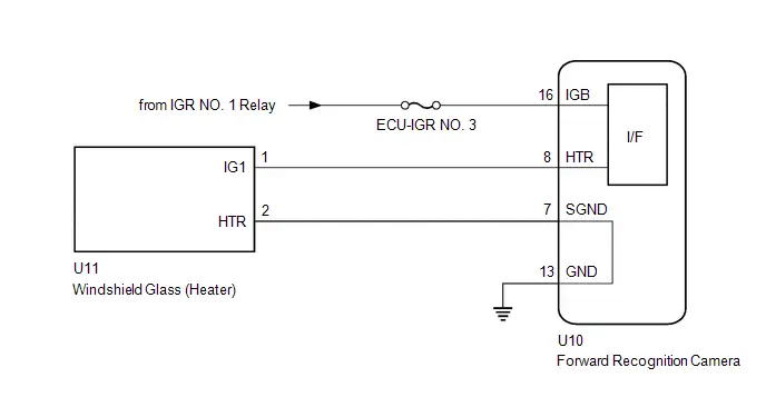
CAUTION / NOTICE / HINT
CAUTION:
To prevent burns due to the heat of the windshield glass (heater), do not touch the area directly.
NOTICE:
- When replacing the forward recognition camera, always replace it with a new one. If a forward recognition camera which was installed to another Toyota Prius vehicle is used, the information stored in the forward recognition camera will not match the information from the vehicle and a DTC may be stored.
- When the forward recognition camera has been replaced with a new one,
make sure to clear all stored vehicle control history of each system and
the forward recognition camera beam axis alignment data.
HINT:
Forward recognition camera beam axis alignment can be performed by using "One Time Recognition", "Driving Adjustment" or "Camera Axis Adjustment Value Write".
One Time Recognition: Click here

Driving Adjustment: Click here

Camera Axis Adjustment Value Write: Click here

- If the forward recognition camera has been replaced with a new one,
make sure to perform Software Version Confirmation.
Click here

- Inspect the fuses for circuits related to this system before performing the following procedure.
PROCEDURE
|
1. |
CLEAR DTC |
(a) Clear the DTCs.
Chassis > Front Recognition Camera > Clear DTCs
|

|
2. |
CHECK FOR DTCs |
Pre-procedure1
(a) Turn the ignition switch to ON and wait for 10 seconds or more.
Procedure1
(b) Check for DTCs.
Chassis > Front Recognition Camera > Trouble Codes|
Result |
Proceed to |
|---|---|
|
C00CA11 is not output |
A |
|
C00CA11 is output |
B |
Post-procedure1
(c) None
| A |

|
USE SIMULATION METHOD TO CHECK |
|

|
3. |
CLEAR DTC |
Pre-procedure1
(a) Disconnect the U11 windshield glass (heater) connector.
Procedure1
(b) Clear the DTCs.
Chassis > Front Recognition Camera > Clear DTCsPost-procedure1
(c) None
|

|
4. |
CHECK WINDSHIELD GLASS (HEATER) |
Pre-procedure1
(a) Turn the ignition switch to ON and wait for 10 seconds or more.
Procedure1
(b) Check for DTCs.
Chassis > Front Recognition Camera > Trouble Codes|
Result |
Proceed to |
|---|---|
|
C00CA11 is not output |
A |
|
C00CA11 is output |
B |
Post-procedure1
(c) None
| A |

|
REPLACE WINDSHIELD GLASS (HEATER)
|


|

|
5. |
CHECK HARNESS AND CONNECTOR (FORWARD RECOGNITION CAMERA - WINDSHIELD GLASS (HEATER)) |
Pre-procedure1
(a) Disconnect the U10 forward recognition camera connector.
Procedure1
(b) Measure the resistance according to the value(s) in the table below.
Standard Resistance:
 Click Location & Routing(U10,U11) Click Connector(U10) Click Connector(U11)
|
Tester Connection |
Condition |
Specified Condition |
Result |
|---|---|---|---|
|
U10-8 (HTR) or U11-1 (IG1) - Body ground and other terminals |
Always |
10 kΩ or higher |
kΩ |
Post-procedure1
(c) None
| OK |

|
REPLACE FORWARD RECOGNITION CAMERA
|


| NG |

|
REPAIR OR REPLACE HARNESS OR CONNECTOR |
Control Module Internal Temperature Sensor "A" Circuit Circuit Voltage Out of Range (C10001C,...,C1A9500)
DESCRIPTION
When an internal malfunction is detected in the forward recognition camera, these DTCs are stored.
|
DTC No. |
Detection Item |
DTC Detection Condition |
Trouble Area |
DTC Output from |
Priority |
|---|---|---|---|---|---|
|
C10001C |
Control Module Internal Temperature Sensor "A" Circuit Circuit Voltage Out of Range |
A forward recognition camera internal malfunction is detected. |
Forward recognition camera |
Front Recognition Camera |
A |
|
C10051C |
Control Module Internal Temperature Sensor "B" Circuit Circuit Voltage Out of Range |
A forward recognition camera internal malfunction is detected. |
Forward recognition camera |
Front Recognition Camera |
A |
|
C100A62 |
Control Module Internal Temperature Sensor A/B Correlation Signal Compare Failure |
A forward recognition camera internal malfunction is detected. |
Forward recognition camera |
Front Recognition Camera |
A |
|
C1A7F49 |
Front Recognition Camera ADC Internal Electronic Failure |
A forward recognition camera internal malfunction is detected. |
Forward recognition camera |
Front Recognition Camera |
A |
|
C1A9346 |
Main Microcomputer in Front Recognition Camera Calibration/Parameter Memory Failure |
A forward recognition camera internal malfunction is detected. |
Forward recognition camera |
Front Recognition Camera |
A |
|
C1A9447 |
Image Processing Microcomputer in Front Recognition Camera Watchdog/Safety MCU Failure |
A forward recognition camera internal malfunction is detected. |
Forward recognition camera |
Front Recognition Camera |
A |
|
C1A9500 |
Image Processing Module Malfunction in Front Recognition Camera |
A forward recognition camera internal malfunction is detected. |
Forward recognition camera |
Front Recognition Camera |
A |
CAUTION / NOTICE / HINT
NOTICE:
- When replacing the forward recognition camera, always replace it with a new one. If a forward recognition camera which was installed to another Toyota Prius vehicle is used, the information stored in the forward recognition camera will not match the information from the vehicle and a DTC may be stored.
- When the forward recognition camera has been replaced with a new one,
make sure to clear all stored vehicle control history of each system and
the forward recognition camera beam axis alignment data.
HINT:
Forward recognition camera beam axis alignment can be performed by using "One Time Recognition", "Driving Adjustment" or "Camera Axis Adjustment Value Write".
One Time Recognition: Click here

Driving Adjustment: Click here

Camera Axis Adjustment Value Write: Click here

- If the forward recognition camera has been replaced with a new one,
make sure to perform Software Version Confirmation.
Click here

PROCEDURE
|
1. |
CHECK FOR DTCs |
Pre-procedure1
(a) Turn the ignition switch off.
(b) Turn the ignition switch to ON and wait 80 seconds or more.
Procedure1
(c) Check for DTCs.
Chassis > Front Recognition Camera > Trouble Codes|
Result |
Proceed to |
|---|---|
|
DTCs are not output |
A |
|
DTCs are output |
B |
Post-procedure1
(d) None
| A |

|
USE SIMULATION METHOD TO CHECK |
| B |

|
REPLACE FORWARD RECOGNITION CAMERA
|


Stop Lamp Relay Actuator Stuck (C138071)
DESCRIPTION
Stop light switch and No. 2 skid control ECU (brake actuator assembly) outputs a stop light signal. When the No. 2 skid control ECU (brake actuator assembly) detects a circuit malfunction related to the stop light, it communicates to the forward recognition camera via CAN and outputs DTC C138071.
|
DTC No. |
Detection Item |
DTC Detection Condition |
Trouble Area |
DTC Output from |
Priority |
|---|---|---|---|---|---|
|
C138071 |
Stop Lamp Relay Actuator Stuck |
When a stop lamp circuit malfunction signal is received from the No. 2 skid control ECU (brake actuator assembly) |
Electronically controlled brake system |
Front Recognition Camera |
B |
PROCEDURE
|
1. |
CHECK ELECTRONICALLY CONTROLLED BRAKE SYSTEM |
HINT:
Click here


| NEXT |

|
END |
Steering Touch Sensor Component Internal Failure (C1A7796)
DESCRIPTION
Forward recognition camera stores DTC C1A7796 when it detects a malfunction or touch sensor malfunction of the multiplex network steering ECU (touch sensor).
|
DTC No. |
Detection Item |
DTC Detection Condition |
Trouble Area |
DTC Output from |
Priority |
|---|---|---|---|---|---|
|
C1A7796 |
Steering Touch Sensor Component Internal Failure |
The forward recognition camera receives malfunction signals from the multiplex network steering ECU.
Malfunction signal send conditions:
|
Steering wheel assembly |
Front Recognition Camera |
A |
WIRING DIAGRAM
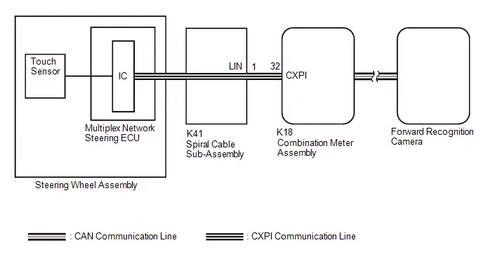
CAUTION / NOTICE / HINT
NOTICE:
The Toyota Prius vehicle is equipped with a Supplemental Restraint System (SRS) which includes components such as airbags. Before servicing (including removal or installation of parts), be sure to read the precaution for Supplemental Restraint System.
Click here

PROCEDURE
|
1. |
REPLACE STEERING WHEEL ASSEMBLY |
HINT:
Click here


| NEXT |

|
END |
Front Recognition Camera Optical Axis Misalignment Malfunction (C1AA800)
DESCRIPTION
The forward recognition camera monitors its optical axis status. If it determines that the optical axis alignment has become misaligned, it will store DTC C1AA800.
|
DTC No. |
Detection Item |
DTC Detection Condition |
Trouble Area |
DTC Output from |
Priority |
|---|---|---|---|---|---|
|
C1AA800 |
Front Recognition Camera Optical Axis Misalignment Malfunction |
When a misalignment of the forward recognition camera is detected |
|
Front Recognition Camera |
A |
CAUTION / NOTICE / HINT
NOTICE:
- When replacing the forward recognition camera, always replace it with a new one. If a forward recognition camera which was installed to another Toyota Prius vehicle is used, the information stored in the forward recognition camera will not match the information from the vehicle and a DTC may be stored.
- When the forward recognition camera has been replaced with a new one,
make sure to clear all stored vehicle control history of each system and
the forward recognition camera beam axis alignment data.
HINT:
Forward recognition camera beam axis alignment can be performed by using "One Time Recognition", "Driving Adjustment" or "Camera Axis Adjustment Value Write".
One Time Recognition: Click here

Driving Adjustment: Click here

Camera Axis Adjustment Value Write: Click here

- If the forward recognition camera has been replaced with a new one,
make sure to perform Software Version Confirmation.
Click here

- When replacing the windshield glass of a Toyota Prius vehicle equipped with a forward recognition camera, make sure to use a Toyota genuine part. If a non-Toyota genuine part is used, the forward recognition camera may not be able to be installed due to a missing bracket or the forward recognition camera may not operate properly due to a difference in the transmissivity or black ceramic border.
- Forward recognition camera optical axis may deviate if the Toyota Prius vehicle is driven on a banked road, such as a racetrack. This deviation can be corrected by driving the vehicle on a normal road for a while.
- Forward recognition camera optical axis may deviate when the vehicle is overloaded or the wheel alignment (toe-in) is incorrect. The forward recognition camera optical axis can be corrected by decreasing the load on the Toyota Prius vehicle or adjusting the toe-in.
PROCEDURE
|
1. |
CHECK FORWARD RECOGNITION CAMERA INSTALLATION |
HINT:
Click here


HINT:
If there is deformation or deviation in the forward recognition camera installation bracket, replace the windshield glass.
OK:
No deformation or deviation in forward recognition camera installation bracket.
| NG |

|
GO TO STEP 11 |
|

|
2. |
CHECK Toyota Prius Vehicle OPERATING CONDITION |
HINT:
Check if a condition which caused the forward recognition camera optical axis to become temporarily misaligned existed, such as if the vehicle was overloaded, towed or modified.
OK:
Vehicle was not overloaded, towed or modified.
| NG |

|
GO TO STEP 9 |
|

|
3. |
CHECK WHEEL ALIGNMENT (TOE) |
HINT:
- for Front Wheel Alignment: Click here


- for Rear Wheel Alignment: Click here


OK:
Front and rear wheels are not misaligned (toe)
| NG |

|
GO TO STEP 6 |
|

|
4. |
PERFORM FORWARD RECOGNITION CAMERA ADJUSTMENT |
HINT:
Forward recognition camera beam axis alignment can be performed by using "One Time Recognition", "Driving Adjustment" or "Camera Axis Adjustment Value Write".
One Time Recognition: Click here

Driving Adjustment: Click here

Camera Axis Adjustment Value Write: Click here

|

|
5. |
CLEAR DTC |
(a) Clear the DTCs.
Chassis > Front Recognition Camera > Clear DTCs| NEXT |

|
END |
|
6. |
ADJUST WHEEL ALIGNMENT (TOE) |
HINT:
- for Front Wheel Alignment: Click here


- for Rear Wheel Alignment: Click here


|

|
7. |
PERFORM FORWARD RECOGNITION CAMERA ADJUSTMENT |
HINT:
Forward recognition camera beam axis alignment can be performed by using "One Time Recognition", "Driving Adjustment" or "Camera Axis Adjustment Value Write".
One Time Recognition: Click here

Driving Adjustment: Click here

Camera Axis Adjustment Value Write: Click here

|

|
8. |
CLEAR DTC |
(a) Clear the DTCs.
Chassis > Front Recognition Camera > Clear DTCs| NEXT |

|
END |
|
9. |
PERFORM FORWARD RECOGNITION CAMERA ADJUSTMENT |
Pre-procedure1
(a) Return the Toyota Prius vehicle to normal operating conditions.
Procedure1
(b) Perform forward recognition camera adjustment.
HINT:
Forward recognition camera beam axis alignment can be performed by using "One Time Recognition", "Driving Adjustment" or "Camera Axis Adjustment Value Write".
One Time Recognition: Click here

Driving Adjustment: Click here

Camera Axis Adjustment Value Write: Click here

Post-procedure1
(c) None
|

|
10. |
CLEAR DTC |
(a) Clear the DTCs.
Chassis > Front Recognition Camera > Clear DTCs| NEXT |

|
END |
|
11. |
REPLACE WINDSHIELD GLASS |
HINT:
Click here


|

|
12. |
PERFORM FORWARD RECOGNITION CAMERA ADJUSTMENT |
HINT:
Forward recognition camera beam axis alignment can be performed by using "One Time Recognition", "Driving Adjustment" or "Camera Axis Adjustment Value Write".
One Time Recognition: Click here

Driving Adjustment: Click here

Camera Axis Adjustment Value Write: Click here

|

|
13. |
CLEAR DTC |
(a) Clear the DTCs.
Chassis > Front Recognition Camera > Clear DTCs| NEXT |

|
END |
Hybrid/EV Powertrain Control Module "A" Unexpected Operation (P0A1D94)
DESCRIPTION
Forward recognition camera receives vehicle specification information from the hybrid vehicle control ECU via CAN communication line. When the vehicle specification information sent from the hybrid vehicle control ECU is abnormal, the forward recognition camera stores DTC P0A1D94.
|
DTC No. |
Detection Item |
DTC Detection Condition |
Trouble Area |
DTC Output from |
Priority |
|---|---|---|---|---|---|
|
P0A1D94 |
Hybrid/EV Powertrain Control Module "A" Unexpected Operation |
When the forward recognition camera receives a cruise control switch input circuit malfunction signal sent from hybrid Toyota Prius vehicle control ECU |
|
Front Recognition Camera |
B |
CAUTION / NOTICE / HINT
NOTICE:
- When replacing the forward recognition camera, always replace it with a new one. If a forward recognition camera which was installed to another Toyota Prius vehicle is used, the information stored in the forward recognition camera will not match the information from the vehicle and a DTC may be stored.
- When the forward recognition camera has been replaced with a new one,
make sure to clear all stored vehicle control history of each system and
the forward recognition camera beam axis alignment data.
HINT:
Forward recognition camera beam axis alignment can be performed by using "One Time Recognition", "Driving Adjustment" or "Camera Axis Adjustment Value Write".
One Time Recognition: Click here

Driving Adjustment: Click here

Camera Axis Adjustment Value Write: Click here

- If the forward recognition camera has been replaced with a new one,
make sure to perform Software Version Confirmation.
Click here

PROCEDURE
|
1. |
CHECK FOR DTC (Hybrid Control) |
(a) Check the DTCs.
Powertrain > Hybrid Control > Trouble Codes|
Result |
Proceed to |
|---|---|
|
Hybrid control system DTCs are not output |
A |
|
Hybrid control system DTCs are output |
B |
| A |

|
REPLACE FORWARD RECOGNITION CAMERA |
| B |

|
GO TO HYBRID CONTROL SYSTEM for 2ZR-FXE: Click here
for M20A-FXS: Click here
|


Lost Communication with Navigation Control Module Missing Message (U016387)
DESCRIPTION
When a malfunction is detected between various ECUs and sensors, these DTCs are stored.
|
DTC No. |
Detection Item |
DTC Detection Condition |
Trouble Area |
DTC Output from |
Priority |
|---|---|---|---|---|---|
|
U016387 |
Lost Communication with Navigation Control Module Missing Message |
When a communication error between forward recognition camera and radio and display receiver assembly is detected |
CAN communication system |
Front Recognition Camera |
B |
PROCEDURE
|
1. |
NAVIGATION INSTALLATION INFORMATION INITIALIZATION |
HINT:
This utility is used to initialize the navigation installation information stored in the front recognition camera.
(a) Following the instructions on the GTS, perform "Navigation Installation Information Initialization".
Chassis > Front Recognition Camera > Utility|
Tester Display |
|---|
|
Navigation Installation Information Initialization |
|

|
2. |
CLEAR DTC |
(a) Clear the DTCs.
Chassis > Front Recognition Camera > Clear DTCs
|

|
3. |
CHECK FOR DTCs |
Pre-procedure1
(a) Make sure that the DTC detection conditions are met.
HINT:
If the detection conditions are not met, the system cannot detect the malfunction.
Procedure1
(b) Check for DTCs.
Chassis > Front Recognition Camera > Trouble Codes|
Result |
Proceed to |
|---|---|
|
DTCs are not output |
A |
|
U016387 is output |
B |
Post-procedure1
(c) None
| A |

|
USE SIMULATION METHOD TO CHECK |
| B |

|
GO TO CAN COMMUNICATION SYSTEM |
Lost Communication with Side Obstacle Detection Control Module "A" Missing Message (U023287,U123687)
DESCRIPTION
Forward recognition camera is connected to the blind spot monitor sensor RH (A)*1 and front side radar sensor (B)*2 by CAN communication line.
If communication with the blind spot monitor sensor RH (A) stops, the forward recognition camera stores DTC U023287.*1
If communication with the front side radar sensor (B) stops, the forward recognition camera stores DTC U123687.*2
|
DTC No. |
Detection Item |
DTC Detection Condition |
Trouble Area |
DTC Output from |
Priority |
|---|---|---|---|---|---|
|
U023287 |
Lost Communication with Side Obstacle Detection Control Module "A" Missing Message |
When a communication error between forward recognition camera and blind spot monitor sensor RH (A) is detected |
|
Front Recognition Camera |
A |
|
U123687 |
Lost Communication with Cruise Control Front Distance Range Sensor Front Side "B" Missing Message |
When a communication error between forward recognition camera and front side radar sensor (B) is detected |
|
Front Recognition Camera |
A |
- *1: w/ Blind Spot Monitor System
- *2: w/ Front Cross Traffic Alert
HINT:
If the DTCs are output simultaneously, the inspection area can be narrowed down.
w/ Blind Spot Monitor System with Front Cross Traffic Alert|
Pattern |
DTC output part name (Display on GTS) |
Suspected Area (Malfunction Status) |
|
|---|---|---|---|
|
Forward Recognition Camera |
|||
|
Front Recognition Camera |
|||
|
U023287 |
U123687 |
||
| ○: DTC is output
-: DTC is not output |
|||
|
Pattern 1 |
○ |
○ |
Harness or connector (Open or short) |
|
Blind spot monitor sensor RH (A) (Internal malfunction) |
|||
|
Front side radar sensor (B) (Internal malfunction) |
|||
|
Clearance warning ECU assembly (Internal malfunction) |
|||
|
No. 1 CAN junction terminal (Internal malfunction) |
|||
|
Forward recognition camera (Internal malfunction) |
|||
|
Pattern 2 |
○ |
- |
Harness or connector (Open) |
|
Blind spot monitor sensor RH (A) (Internal malfunction) |
|||
|
Pattern 3 |
- |
○ |
Harness or connector (Open) |
|
Front side radar sensor (B) (Internal malfunction) |
|||
|
Pattern |
DTC output part name (Display on GTS) |
Suspected Area (Malfunction Status) |
|---|---|---|
|
Forward Recognition Camera |
||
|
Front Recognition Camera |
||
|
U023287 |
||
| ○: DTC is output
-: DTC is not output |
||
|
Pattern 1 |
○ |
Harness or connector (Open or short) |
|
Blind spot monitor sensor RH (A) (Internal malfunction) |
||
|
Clearance warning ECU assembly (Internal malfunction) |
||
|
No. 1 CAN junction terminal (Internal malfunction) |
||
|
Forward recognition camera (Internal malfunction) |
||
WIRING DIAGRAM
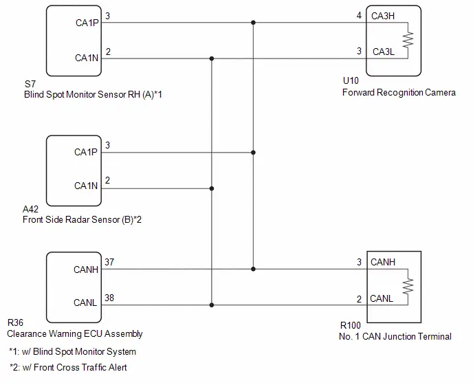
CAUTION / NOTICE / HINT
NOTICE:
- When replacing the forward recognition camera, always replace it with a new one. If a forward recognition camera which was installed to another Toyota Prius vehicle is used, the information stored in the forward recognition camera will not match the information from the vehicle and a DTC may be stored.
- When the forward recognition camera has been replaced with a new one,
make sure to clear all stored vehicle control history of each system and
the forward recognition camera beam axis alignment data.
HINT:
Forward recognition camera beam axis alignment can be performed by using "One Time Recognition", "Driving Adjustment" or "Camera Axis Adjustment Value Write".
One Time Recognition: Click here

Driving Adjustment: Click here

Camera Axis Adjustment Value Write: Click here

- If the forward recognition camera has been replaced with a new one,
make sure to perform Software Version Confirmation.
Click here

- After the ignition switch is turned off, there may be a waiting time
before disconnecting the negative (-) auxiliary battery terminal.
Click here

HINT:
When disconnecting and reconnecting the auxiliary battery, there is an automatic learning function that completes learning when the respective system is used.
Click here


PROCEDURE
|
1. |
CONFIRM MODEL |
(a) Choose the model to be inspected.
|
Result |
Proceed to |
|---|---|
|
w/ Blind Spot Monitor System with Front Cross Traffic Alert |
A |
|
w/ Blind Spot Monitor System without Front Cross Traffic Alert |
B |
| B |

|
GO TO STEP 13 |
|

|
2. |
CHECK FOR DTCs |
(a) Read each DTC and check the diagnosis pattern using the table below.
Chassis > Front Recognition Camera > Trouble Codes|
Pattern |
DTC output part name (Display on GTS) |
|
|---|---|---|
|
Front Recognition Camera |
||
|
Pattern 1 |
U023287 |
U123687 |
|
Pattern 2 |
U023287 |
- |
|
Pattern 3 |
- |
U123687 |
|
Result |
Proceed to |
|---|---|
|
Pattern 1 |
A |
|
Pattern 2 |
B |
|
Pattern 3 |
C |
| B |

|
GO TO STEP 11 |
| C |

|
GO TO STEP 12 |
|

|
3. |
CLEAR DTC |
Pre-procedure1
(a) Disconnect the S7 blind spot monitor sensor RH (A) connector.
Procedure1
(b) Clear the DTCs.
Chassis > Front Recognition Camera > Clear DTCsPost-procedure1
(c) None
|

|
4. |
INSPECT BLIND SPOT MONITOR SENSOR RH (A) |
(a) Check for DTCs.
Chassis > Front Recognition Camera > Trouble Codes|
Result |
Proceed to |
|---|---|
|
U023287 is output |
A |
|
U023287 and U123687 are output |
B |
| A |

|
REPLACE BLIND SPOT MONITOR SENSOR RH (A)
|


|

|
5. |
CLEAR DTC |
Pre-procedure1
(a) Connect the S7 blind spot monitor sensor RH (A) connector.
(b) Disconnect the A42 front side radar sensor (B) connector.
Procedure1
(c) Clear the DTCs.
Chassis > Front Recognition Camera > Clear DTCsPost-procedure1
(d) None
|

|
6. |
INSPECT FRONT SIDE RADAR SENSOR (B) |
(a) Check for DTCs.
Chassis > Front Recognition Camera > Trouble Codes|
Result |
Proceed to |
|---|---|
|
U123687 is output |
A |
|
U023287 and U123687 are output |
B |
| A |

|
REPLACE FRONT SIDE RADAR SENSOR (B)
|


|

|
7. |
CLEAR DTC |
Pre-procedure1
(a) Connect the A42 front side radar sensor (B) connector.
(b) Disconnect the R36 clearance warning ECU assembly connector.
Procedure1
(c) Clear the DTCs.
Chassis > Front Recognition Camera > Clear DTCsPost-procedure1
(d) None
|

|
8. |
INSPECT CLEARANCE WARNING ECU ASSEMBLY |
(a) Check for DTCs.
Chassis > Front Recognition Camera > Trouble Codes|
Result |
Proceed to |
|---|---|
|
DTCs are not output |
A |
|
U023287 and U123687 are output |
B |
| A |

|
REPLACE CLEARANCE WARNING ECU ASSEMBLY |
|

|
9. |
CHECK CAN MAIN WIRE (FORWARD RECOGNITION CAMERA) |
Pre-procedure1
(a) Disconnect the cable from the negative (-) auxiliary battery terminal.
(b) Disconnect the U10 forward recognition camera connector.
Procedure1
(c) Measure the resistance according to the value(s) in the table below.
Standard Resistance:
 Click Location & Routing(U10) Click Connector(U10)
|
Tester Connection |
Condition |
Specified Condition |
Result |
|---|---|---|---|
|
U10-3 (CA3L) - U10-4 (CA3H) |
Cable disconnected from negative (-) auxiliary battery terminal |
108 to 132 Ω |
Ω |
|
U10-3 (CA3L) - Body ground |
Cable disconnected from negative (-) auxiliary battery terminal |
200 Ω or higher |
Ω |
|
U10-4 (CA3H) - Body ground |
Cable disconnected from negative (-) auxiliary battery terminal |
200 Ω or higher |
Ω |
|
U10-3 (CA3L) - B |
Cable disconnected from negative (-) auxiliary battery terminal |
6 kΩ or higher |
kΩ |
|
U10-4 (CA3H) - B |
Cable disconnected from negative (-) auxiliary battery terminal |
6 kΩ or higher |
kΩ |
Post-procedure1
(d) None
| OK |

|
REPLACE FORWARD RECOGNITION CAMERA
|


|

|
10. |
CHECK CAN MAIN WIRE (NO. 1 CAN JUNCTION TERMINAL) |
Pre-procedure1
(a) Disconnect the cable from the negative (-) auxiliary battery terminal.
(b) Connect the U10 forward recognition camera connector.
(c) Disconnect the R100 No. 1 CAN junction terminal connector.
Procedure1
(d) Measure the resistance according to the value(s) in the table below.
Standard Resistance:
 Click Location & Routing(R100) Click Connector(R100)
|
Tester Connection |
Condition |
Specified Condition |
Result |
|---|---|---|---|
|
R100-2 (CANL) - R100-3 (CANH) |
Cable disconnected from negative (-) auxiliary battery terminal |
108 to 132 Ω |
Ω |
|
R100-2 (CANL) - Body ground |
Cable disconnected from negative (-) auxiliary battery terminal |
200 Ω or higher |
Ω |
|
R100-3 (CANH) - Body ground |
Cable disconnected from negative (-) auxiliary battery terminal |
200 Ω or higher |
Ω |
|
R100-2 (CANL) - B |
Cable disconnected from negative (-) auxiliary battery terminal |
6 kΩ or higher |
kΩ |
|
R100-3 (CANH) - B |
Cable disconnected from negative (-) auxiliary battery terminal |
6 kΩ or higher |
kΩ |
Post-procedure1
(e) None
| OK |

|
REPLACE NO. 1 CAN JUNCTION TERMINAL |
| NG |

|
REPAIR OR REPLACE HARNESS OR CONNECTOR |
|
11. |
CHECK CAN MAIN WIRE (BLIND SPOT MONITOR SENSOR RH (A)) |
Pre-procedure1
(a) Disconnect the cable from the negative (-) auxiliary battery terminal.
(b) Disconnect the S7 blind spot monitor sensor RH (A) connector.
Procedure1
(c) Measure the resistance according to the value(s) in the table below.
Standard Resistance:
 Click Location & Routing(S7) Click Connector(S7)
|
Tester Connection |
Condition |
Specified Condition |
Result |
|---|---|---|---|
|
S7-3 (CA1P) - S7-2 (CA1N) |
Cable disconnected from negative (-) auxiliary battery terminal |
54 to 69 Ω |
Ω |
Post-procedure1
(d) None
| OK |

|
REPLACE BLIND SPOT MONITOR SENSOR RH (A)
|


| NG |

|
REPAIR OR REPLACE HARNESS OR CONNECTOR |
|
12. |
CHECK CAN MAIN WIRE (FRONT SIDE RADAR SENSOR (B)) |
Pre-procedure1
(a) Disconnect the cable from the negative (-) auxiliary battery terminal.
(b) Disconnect the A42 front side radar sensor (B) connector.
Procedure1
(c) Measure the resistance according to the value(s) in the table below.
Standard Resistance:
 Click Location & Routing(A42) Click Connector(A42)
|
Tester Connection |
Condition |
Specified Condition |
Result |
|---|---|---|---|
|
A42-3 (CA1P) - A42-2 (CA1N) |
Cable disconnected from negative (-) auxiliary battery terminal |
54 to 69 Ω |
Ω |
Post-procedure1
(d) None
| OK |

|
REPLACE FRONT SIDE RADAR SENSOR (B)
|


| NG |

|
REPAIR OR REPLACE HARNESS OR CONNECTOR |
|
13. |
CLEAR DTC |
Pre-procedure1
(a) Disconnect the R36 clearance warning ECU assembly connector.
Procedure1
(b) Clear the DTCs.
Chassis > Front Recognition Camera > Clear DTCsPost-procedure1
(c) None
|

|
14. |
INSPECT CLEARANCE WARNING ECU ASSEMBLY |
(a) Check for DTCs.
Chassis > Front Recognition Camera > Trouble Codes|
Result |
Proceed to |
|---|---|
|
DTCs are not output |
A |
|
U023287 is output |
B |
| A |

|
REPLACE CLEARANCE WARNING ECU ASSEMBLY |
|

|
15. |
CLEAR DTC |
Pre-procedure1
(a) Disconnect the R100 No. 1 CAN junction terminal connector.
Procedure1
(b) Clear the DTCs.
Chassis > Front Recognition Camera > Clear DTCsPost-procedure1
(c) None
|

|
16. |
INSPECT NO. 1 CAN JUNCTION TERMINAL |
(a) Check for DTCs.
Chassis > Front Recognition Camera > Trouble Codes|
Result |
Proceed to |
|---|---|
|
DTCs are not output |
A |
|
U023287 is output |
B |
| A |

|
REPLACE NO. 1 CAN JUNCTION TERMINAL |
|

|
17. |
CHECK CAN MAIN WIRE (BLIND SPOT MONITOR SENSOR RH (A)) |
Pre-procedure1
(a) Disconnect the cable from the negative (-) auxiliary battery terminal.
(b) Connect the R100 No. 1 CAN junction terminal connector.
(c) Disconnect the S7 blind spot monitor sensor RH (A) connector.
Procedure1
(d) Measure the resistance according to the value(s) in the table below.
Standard Resistance:
 Click Location & Routing(S7) Click Connector(S7)
|
Tester Connection |
Condition |
Specified Condition |
Result |
|---|---|---|---|
|
S7-3 (CA1P) - S7-2 (CA1N) |
Cable disconnected from negative (-) auxiliary battery terminal |
54 to 69 Ω |
Ω |
Post-procedure1
(e) None
| NG |

|
REPAIR OR REPLACE HARNESS OR CONNECTOR |
|

|
18. |
CHECK FORWARD RECOGNITION CAMERA |
Pre-procedure1
(a) Disconnect the S7 blind spot monitor sensor RH (A) connector.
Procedure1
(b) Using an oscilloscope, check the waveform.
OK:
 Click Location & Routing(S7) Click Connector(S7)
|
Tester Connection |
Condition |
Tool Setting |
Specified Condition |
|---|---|---|---|
|
S7-3 (CA1P) - S7-2 (CA1N) |
Ignition switch ON |
1V/DIV., 100μs./DIV. |
Pulse generation |
Post-procedure1
(c) None
| OK |

|
REPLACE BLIND SPOT MONITOR SENSOR RH (A)
|


| NG |

|
REPLACE FORWARD RECOGNITION CAMERA
|


Lost Communication with Cruise Control Front Distance Range Sensor Single Sensor or Center Missing Message (U023587)
DESCRIPTION
The forward recognition camera communicates with the millimeter wave radar sensor assembly via CAN communication line. If communication with the millimeter wave radar sensor assembly stops, the forward recognition camera stores DTC U023587.
|
DTC No. |
Detection Item |
DTC Detection Condition |
Trouble Area |
DTC Output from |
Priority |
|---|---|---|---|---|---|
|
U023587 |
Lost Communication with Cruise Control Front Distance Range Sensor Single Sensor or Center Missing Message |
When a communication error between forward recognition camera and millimeter wave radar sensor assembly is detected |
|
Front Recognition Camera |
A |
- *: w/ Advanced Park
HINT:
If the DTCs are output simultaneously, the inspection area can be narrowed down.
w/ Advanced Park|
Pattern |
DTC output part name (Display on GTS) |
Suspected Area (Malfunction Status) |
|||
|---|---|---|---|---|---|
|
Forward Recognition Camera |
Millimeter Wave Radar Sensor Assembly |
Clearance Warning ECU Assembly |
Parking Assist ECU |
||
|
Front Recognition Camera |
Front Radar Sensor |
Clearance Warning |
Circumference Monitoring Camera Control Module |
||
|
U023587 |
U010487 |
U117987 |
U11B687 |
||
| ○: DTC is output
-: DTC is not output |
|||||
|
Pattern 1 |
○ |
○ |
○ |
○ |
Harness or connector (Open or short) |
|
Millimeter wave radar sensor assembly (Internal malfunction) |
|||||
|
Clearance warning ECU assembly (Internal malfunction) |
|||||
|
Parking assist ECU (Internal malfunction) |
|||||
|
Forward recognition camera (Internal malfunction) |
|||||
|
Pattern 2 |
○ |
- |
- |
- |
Connector (Poor connector) |
|
Harness or connector (Open) |
|||||
|
Millimeter wave radar sensor assembly (Internal malfunction) |
|||||
|
Forward recognition camera (Internal malfunction) |
|||||
|
Pattern |
DTC output part name (Display on GTS) |
Suspected Area (Malfunction Status) |
|
|---|---|---|---|
|
Forward Recognition Camera |
Millimeter Wave Radar Sensor Assembly |
||
|
Front Recognition Camera |
Front Radar Sensor |
||
|
U023587 |
U010487 |
||
| ○: DTC is output
-: DTC is not output |
|||
|
Pattern 1 |
○ |
○ |
Harness or connector (Open or short) |
|
Millimeter wave radar sensor assembly (Internal malfunction) |
|||
|
Forward recognition camera (Internal malfunction) |
|||
|
Pattern 2 |
○ |
- |
Connector (Poor connector) |
|
Harness or connector (Open) |
|||
|
Millimeter wave radar sensor assembly (Internal malfunction) |
|||
|
Forward recognition camera (Internal malfunction) |
|||
WIRING DIAGRAM
w/ Advanced Park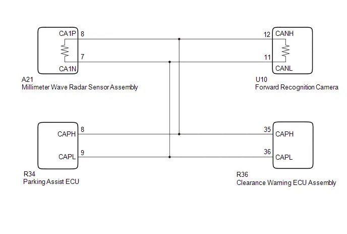 w/o Advanced Park
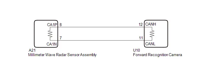
CAUTION / NOTICE / HINT
NOTICE:
- When replacing the millimeter wave radar sensor assembly, always replace it with a new one. If a millimeter wave radar sensor assembly which was installed to another Toyota Prius vehicle is used, the information stored in the millimeter wave radar sensor assembly will not match the information from the vehicle and a DTC may be stored.
- When the millimeter wave radar sensor assembly has been replaced with
a new one, it is necessary to perform millimeter wave radar sensor assembly
beam axis alignment and to clear the Toyota Prius vehicle control history.
Before performing the Driving Adjustment, make sure to read Before Starting
Driving Adjustment.
HINT:
Beam axis alignment of the millimeter wave radar sensor assembly can be performed using either Triangle Target, Flat Surface Target or Driving Adjustment.
Triangle Target: Click here

Flat Surface Target: Click here

Driving Adjustment: Click here

- When replacing the forward recognition camera, always replace it with a new one. If a forward recognition camera which was installed to another Toyota Prius vehicle is used, the information stored in the forward recognition camera will not match the information from the vehicle and a DTC may be stored.
- When the forward recognition camera has been replaced with a new one,
make sure to clear all stored vehicle control history of each system and
the forward recognition camera beam axis alignment data.
HINT:
Forward recognition camera beam axis alignment can be performed by using "One Time Recognition", "Driving Adjustment" or "Camera Axis Adjustment Value Write".
One Time Recognition: Click here

Driving Adjustment: Click here

Camera Axis Adjustment Value Write: Click here

- If the forward recognition camera has been replaced with a new one,
make sure to perform Software Version Confirmation.
Click here

- After the ignition switch is turned off, there may be a waiting time
before disconnecting the negative (-) auxiliary battery terminal.
Click here

HINT:
When disconnecting and reconnecting the auxiliary battery, there is an automatic learning function that completes learning when the respective system is used.
Click here


PROCEDURE
|
1. |
CONFIRM MODEL |
(a) Choose the model to be inspected.
|
Result |
Proceed to |
|---|---|
|
w/ Advanced Park |
A |
|
w/o Advanced Park |
B |
| B |

|
GO TO STEP 14 |
|

|
2. |
CHECK FOR DTCs |
(a) Read each DTC and check the diagnosis pattern using the table below.
Chassis > Front Recognition Camera > Trouble Codes Body Electrical > Front Radar Sensor > Trouble Codes Body Electrical > Clearance Warning > Trouble Codes Chassis > Circumference Monitoring Camera Control Module > Trouble Codes|
Pattern |
DTC output part name (Display on GTS) |
|||
|---|---|---|---|---|
|
Front Recognition Camera |
Front Radar Sensor |
Clearance Warning |
Circumference Monitoring Camera Control Module |
|
|
Pattern 1 |
U023587 |
U010487 |
U117987 |
U11B687 |
|
Pattern 2 |
U023587 |
- |
- |
- |
|
Result |
Proceed to |
|---|---|
|
Pattern 1 |
A |
|
Pattern 2 |
B |
| B |

|
GO TO STEP 9 |
|

|
3. |
CLEAR DTC |
Pre-procedure1
(a) Disconnect the R36 clearance warning ECU assembly connector.
Procedure1
(b) Clear the DTCs.
Chassis > Front Recognition Camera > Clear DTCsPost-procedure1
(c) None
|

|
4. |
INSPECT CLEARANCE WARNING ECU ASSEMBLY |
(a) Check for DTCs.
Chassis > Front Recognition Camera > Trouble Codes|
Result |
Proceed to |
|---|---|
|
U023587 is not output |
A |
|
U023587 is output |
B |
| A |

|
REPLACE CLEARANCE WARNING ECU ASSEMBLY |
|

|
5. |
CLEAR DTC |
Pre-procedure1
(a) Connect the R36 clearance warning ECU assembly connector.
(b) Disconnect the R34 parking assist ECU connector.
Procedure1
(c) Clear the DTCs.
Chassis > Front Recognition Camera > Clear DTCsPost-procedure1
(d) None
|

|
6. |
INSPECT PARKING ASSIST ECU |
(a) Check for DTCs.
Chassis > Front Recognition Camera > Trouble Codes|
Result |
Proceed to |
|---|---|
|
U023587 is not output |
A |
|
U023587 is output |
B |
| A |

|
REPLACE PARKING ASSIST ECU |
|

|
7. |
CHECK CAN MAIN WIRE (FORWARD RECOGNITION CAMERA) |
Pre-procedure1
(a) Disconnect the cable from the negative (-) auxiliary battery terminal.
(b) Connect the R34 parking assist ECU connector.
(c) Disconnect the U10 forward recognition camera connector.
Procedure1
(d) Measure the resistance according to the value(s) in the table below.
Standard Resistance:
 Click Location & Routing(U10) Click Connector(U10)
|
Tester Connection |
Condition |
Specified Condition |
Result |
|---|---|---|---|
|
U10-12 (CANH) - U10-11 (CANL) |
Cable disconnected from negative (-) auxiliary battery terminal |
108 to 132 Ω |
Ω |
|
U10-12 (CANH) - Body ground |
Cable disconnected from negative (-) auxiliary battery terminal |
200 Ω or higher |
Ω |
|
U10-11 (CANL) - Body ground |
Cable disconnected from negative (-) auxiliary battery terminal |
200 Ω or higher |
Ω |
|
U10-12 (CANH) - B |
Cable disconnected from negative (-) auxiliary battery terminal |
6 kΩ or higher |
kΩ |
|
U10-11 (CANL) - B |
Cable disconnected from negative (-) auxiliary battery terminal |
6 kΩ or higher |
kΩ |
Post-procedure1
(e) None
| OK |

|
REPLACE FORWARD RECOGNITION CAMERA
|


|

|
8. |
CHECK CAN MAIN WIRE (MILLIMETER WAVE RADAR SENSOR ASSEMBLY) |
Pre-procedure1
(a) Connect the U10 forward recognition camera connector.
(b) Disconnect the A21 millimeter wave radar sensor assembly connector.
Procedure1
(c) Measure the resistance according to the value(s) in the table below.
Standard Resistance:
 Click Location & Routing(A21) Click Connector(A21)
|
Tester Connection |
Condition |
Specified Condition |
Result |
|---|---|---|---|
|
A21-8 (CA1P) - A21-7 (CA1N) |
Cable disconnected from negative (-) auxiliary battery terminal |
108 to 132 Ω |
Ω |
|
A21-8 (CA1P) - Body ground |
Cable disconnected from negative (-) auxiliary battery terminal |
200 Ω or higher |
Ω |
|
A21-7 (CA1N) - Body ground |
Cable disconnected from negative (-) auxiliary battery terminal |
200 Ω or higher |
Ω |
|
A21-8 (CA1P) - B |
Cable disconnected from negative (-) auxiliary battery terminal |
6 kΩ or higher |
kΩ |
|
A21-7 (CA1N) - B |
Cable disconnected from negative (-) auxiliary battery terminal |
6 kΩ or higher |
kΩ |
Post-procedure1
(d) None
| OK |

|
REPLACE MILLIMETER WAVE RADAR SENSOR ASSEMBLY Click here
NOTICE: Before replacing the millimeter wave radar sensor assembly, make sure to turn the ignition switch from off to ON and check for DTCs. |


| NG |

|
REPAIR OR REPLACE HARNESS OR CONNECTOR |
|
9. |
CHECK CONNECTION OF CONNECTORS |
(a) Check that the connectors are properly connected to the forward recognition camera and millimeter wave radar sensor assembly.
OK:
The connectors are properly connected
| NG |

|
CONNECT CONNECTORS PROPERLY |
|

|
10. |
CLEAR DTC |
(a) Clear the DTCs.
Chassis > Front Recognition Camera > Clear DTCs
|

|
11. |
CHECK FOR DTCs |
Pre-procedure1
(a) Turn the ignition switch off.
(b) Turn the ignition switch to ON.
(c) Make sure that the DTC detection conditions are met.
HINT:
If the detection conditions are not met, the system cannot detect the malfunction.
Procedure1
(d) Check for DTCs.
Chassis > Front Recognition Camera > Trouble Codes|
Result |
Proceed to |
|---|---|
|
U023587 is not output |
A |
|
U023587 is output |
B |
Post-procedure1
(e) None
| A |

|
END |
|

|
12. |
CHECK CAN MAIN WIRE (FORWARD RECOGNITION CAMERA) |
Pre-procedure1
(a) Disconnect the cable from the negative (-) auxiliary battery terminal.
(b) Disconnect the U10 forward recognition camera connector.
Procedure1
(c) Measure the resistance according to the value(s) in the table below.
Standard Resistance:
 Click Location & Routing(U10) Click Connector(U10)
|
Tester Connection |
Condition |
Specified Condition |
Result |
|---|---|---|---|
|
U10-12 (CANH) - U10-11 (CANL) |
Cable disconnected from negative (-) auxiliary battery terminal |
108 to 132 Ω |
Ω |
Post-procedure1
(d) None
| NG |

|
REPAIR OR REPLACE HARNESS OR CONNECTOR |
|

|
13. |
CHECK MILLIMETER WAVE RADAR SENSOR ASSEMBLY |
Pre-procedure1
(a) Disconnect the R36 clearance warning ECU assembly connector.
(b) Disconnect the R34 parking assist ECU connector.
(c) Disconnect the U10 forward recognition camera connector.
Procedure1
(d) Using an oscilloscope, check the waveform.
OK:
 Click Location & Routing(U10) Click Connector(U10)
|
Tester Connection |
Condition |
Tool Setting |
Specified Condition |
|---|---|---|---|
|
U10-12 (CANH) - U10-11 (CANL) |
Ignition switch ON |
1V/DIV., 100μs./DIV. |
Pulse generation |
Post-procedure1
(e) None
| OK |

|
REPLACE FORWARD RECOGNITION CAMERA
|


| NG |

|
REPLACE MILLIMETER WAVE RADAR SENSOR ASSEMBLY
|


|
14. |
CHECK FOR DTCs |
(a) Read each DTC and check the diagnosis pattern using the table below.
Chassis > Front Recognition Camera > Trouble Codes Body Electrical > Front Radar Sensor > Trouble Codes|
Pattern |
DTC output part name (Display on GTS) |
|
|---|---|---|
|
Front Recognition Camera |
Front Radar Sensor |
|
|
Pattern 1 |
U023587 |
U010487 |
|
Pattern 2 |
U023587 |
- |
|
Result |
Proceed to |
|---|---|
|
Pattern 1 |
A |
|
Pattern 2 |
B |
| B |

|
GO TO STEP 17 |
|

|
15. |
CHECK CAN MAIN WIRE (FORWARD RECOGNITION CAMERA) |
Pre-procedure1
(a) Disconnect the cable from the negative (-) auxiliary battery terminal.
(b) Disconnect the U10 forward recognition camera connector.
Procedure1
(c) Measure the resistance according to the value(s) in the table below.
Standard Resistance:
 Click Location & Routing(U10) Click Connector(U10)
|
Tester Connection |
Condition |
Specified Condition |
Result |
|---|---|---|---|
|
U10-12 (CANH) - U10-11 (CANL) |
Cable disconnected from negative (-) auxiliary battery terminal |
108 to 132 Ω |
Ω |
|
U10-12 (CANH) - Body ground |
Cable disconnected from negative (-) auxiliary battery terminal |
200 Ω or higher |
Ω |
|
U10-11 (CANL) - Body ground |
Cable disconnected from negative (-) auxiliary battery terminal |
200 Ω or higher |
Ω |
|
U10-12 (CANH) - B |
Cable disconnected from negative (-) auxiliary battery terminal |
6 kΩ or higher |
kΩ |
|
U10-11 (CANL) - B |
Cable disconnected from negative (-) auxiliary battery terminal |
6 kΩ or higher |
kΩ |
Post-procedure1
(d) None
| OK |

|
REPLACE FORWARD RECOGNITION CAMERA
|


|

|
16. |
CHECK CAN MAIN WIRE (MILLIMETER WAVE RADAR SENSOR ASSEMBLY) |
Pre-procedure1
(a) Connect the U10 forward recognition camera connector.
(b) Disconnect the A21 millimeter wave radar sensor assembly connector.
Procedure1
(c) Measure the resistance according to the value(s) in the table below.
Standard Resistance:
 Click Location & Routing(A21) Click Connector(A21)
|
Tester Connection |
Condition |
Specified Condition |
Result |
|---|---|---|---|
|
A21-8 (CA1P) - A21-7 (CA1N) |
Cable disconnected from negative (-) auxiliary battery terminal |
108 to 132 Ω |
Ω |
|
A21-8 (CA1P) - Body ground |
Cable disconnected from negative (-) auxiliary battery terminal |
200 Ω or higher |
Ω |
|
A21-7 (CA1N) - Body ground |
Cable disconnected from negative (-) auxiliary battery terminal |
200 Ω or higher |
Ω |
|
A21-8 (CA1P) - B |
Cable disconnected from negative (-) auxiliary battery terminal |
6 kΩ or higher |
kΩ |
|
A21-7 (CA1N) - B |
Cable disconnected from negative (-) auxiliary battery terminal |
6 kΩ or higher |
kΩ |
Post-procedure1
(d) None
| OK |

|
REPLACE MILLIMETER WAVE RADAR SENSOR ASSEMBLY Click here
NOTICE: Before replacing the millimeter wave radar sensor assembly, make sure to turn the ignition switch from off to ON and check for DTCs. |


| NG |

|
REPAIR OR REPLACE HARNESS OR CONNECTOR |
|
17. |
CHECK CONNECTION OF CONNECTORS |
(a) Check that the connectors are properly connected to the forward recognition camera and millimeter wave radar sensor assembly.
OK:
The connectors are properly connected
| NG |

|
CONNECT CONNECTORS PROPERLY |
|

|
18. |
CLEAR DTC |
(a) Clear the DTCs.
Chassis > Front Recognition Camera > Clear DTCs
|

|
19. |
CHECK FOR DTCs |
Pre-procedure1
(a) Turn the ignition switch off.
(b) Turn the ignition switch to ON.
(c) Make sure that the DTC detection conditions are met.
HINT:
If the detection conditions are not met, the system cannot detect the malfunction.
Procedure1
(d) Check for DTCs.
Chassis > Front Recognition Camera > Trouble Codes|
Result |
Proceed to |
|---|---|
|
U023587 is not output |
A |
|
U023587 is output |
B |
Post-procedure1
(e) None
| A |

|
END |
|

|
20. |
CHECK CAN MAIN WIRE (FORWARD RECOGNITION CAMERA) |
Pre-procedure1
(a) Disconnect the cable from the negative (-) auxiliary battery terminal.
(b) Disconnect the U10 forward recognition camera connector.
Procedure1
(c) Measure the resistance according to the value(s) in the table below.
Standard Resistance:
 Click Location & Routing(U10) Click Connector(U10)
|
Tester Connection |
Condition |
Specified Condition |
Result |
|---|---|---|---|
|
U10-12 (CANH) - U10-11 (CANL) |
Cable disconnected from negative (-) auxiliary battery terminal |
108 to 132 Ω |
Ω |
Post-procedure1
(d) None
| NG |

|
REPAIR OR REPLACE HARNESS OR CONNECTOR |
|

|
21. |
CHECK MILLIMETER WAVE RADAR SENSOR ASSEMBLY |
Pre-procedure1
(a) Disconnect the U10 forward recognition camera connector.
Procedure1
(b) Using an oscilloscope, check the waveform.
OK:
 Click Location & Routing(U10) Click Connector(U10)
|
Tester Connection |
Condition |
Tool Setting |
Specified Condition |
|---|---|---|---|
|
U10-12 (CANH) - U10-11 (CANL) |
Ignition switch ON |
1V/DIV., 100μs./DIV. |
Pulse generation |
Post-procedure1
(c) None
| OK |

|
REPLACE FORWARD RECOGNITION CAMERA
|


| NG |

|
REPLACE MILLIMETER WAVE RADAR SENSOR ASSEMBLY
|


Internal Control Module Software Incompatibility Not Programmed (U030051,U030057,U030157)
DESCRIPTION
- Forward recognition camera receives Powertrain Information from the hybrid vehicle control ECU via CAN communication line.
- If the forward recognition camera cannot confirm the Powertrain Information based on Powertrain Information sent from the hybrid Toyota Prius vehicle control ECU, the forward recognition camera stores DTC U030051.
- When the Powertrain Information value sent from the hybrid vehicle control ECU does not match the value stored in the forward recognition camera, the forward recognition camera stores DTC U030057.
- When the value of the engine type information sent from the hybrid Toyota Prius vehicle control ECU does not match the value stored in the forward recognition camera, the forward recognition camera stores DTC U030157.
|
DTC No. |
Detection Item |
DTC Detection Condition |
Trouble Area |
DTC Output from |
Priority |
|---|---|---|---|---|---|
|
U030051 |
Internal Control Module Software Incompatibility Not Programmed |
When the forward recognition camera cannot confirm the Powertrain Information based on Powertrain Information sent from the hybrid Toyota Prius vehicle control ECU |
|
Front Recognition Camera |
B |
|
U030057 |
Internal Control Module Software Incompatibility Invalid/Incompatible Software Component |
When the Powertrain Information value sent from the hybrid Toyota Prius vehicle control ECU does not match the value stored in the forward recognition camera |
|
Front Recognition Camera |
B |
|
U030157 |
Software Incompatibility with ECM/PCM Invalid/Incompatible Software Component |
When the powertrain information sent from the hybrid Toyota Prius vehicle control ECU does not match the value stored in the forward recognition camera |
|
Front Recognition Camera |
B |
CAUTION / NOTICE / HINT
NOTICE:
- When replacing the forward recognition camera, always replace it with a new one. If a forward recognition camera which was installed to another Toyota Prius vehicle is used, the information stored in the forward recognition camera will not match the information from the vehicle and a DTC may be stored.
- When the forward recognition camera has been replaced with a new one,
make sure to clear all stored vehicle control history of each system and
the forward recognition camera beam axis alignment data.
HINT:
Forward recognition camera beam axis alignment can be performed by using "One Time Recognition", "Driving Adjustment" or "Camera Axis Adjustment Value Write".
One Time Recognition: Click here

Driving Adjustment: Click here

Camera Axis Adjustment Value Write: Click here

- If the forward recognition camera has been replaced with a new one,
make sure to perform Software Version Confirmation.
Click here

- Before replacing the hybrid Toyota Prius vehicle control ECU, refer
to registration.
Click here

PROCEDURE
|
1. |
CHECK FOR DTCs (Hybrid Control) |
(a) Check for DTCs.
Powertrain > Hybrid Control > Trouble CodesHINT:
If DTC U030051, U030057 or U030157 is output, inspect the hybrid control system first as a hybrid control system DTC may be stored.
|
Result |
Proceed to |
|---|---|
|
Hybrid control system DTC is not output |
A |
|
Hybrid control system DTC is output |
B |
| B |

|
GO TO HYBRID CONTROL SYSTEM for 2ZR-FXE: Click here
for M20A-FXS: Click here
|


|

|
2. |
CHECK FOR DTCs (HEALTH CHECK) |
(a) Using the GTS, perform a health check.
OK:
ECUs other than the forward recognition camera do not output specification information mismatch DTCs related to the hybrid Toyota Prius vehicle control ECU.
|
Result |
Proceed to |
|---|---|
|
DTC is not output |
A |
|
DTC is output |
B |
| B |

|
REPLACE HYBRID Toyota Prius Vehicle CONTROL ECU |
|

|
3. |
READ VALUE USING GTS (Powertrain Information) |
(a) Using the GTS, read the Data List.
Chassis > Front Recognition Camera > Data List|
Tester Display |
Measurement Item |
Range |
Normal Condition |
Diagnostic Note |
|---|---|---|---|---|
|
Powertrain Information |
Powertrain information |
Conventional, SS, HV, PHV, EV, 1MHV, FCV or Default Value |
Conventional: Conventional Toyota Prius vehicle SS: w/ Stop and start vehicle HV: HEV PHV: PHEV EV: BEV 1MHV: 1MHV FCV: FCEV Default Value: Vehicle information not confirmed |
- |
|
Tester Display |
|---|
|
Powertrain Information |
HINT:
- When the specification stored by the forward recognition camera and the Toyota Prius vehicle specification do not match, there is a malfunction in the specification information stored by the forward recognition camera. Therefore, replace the forward recognition camera.
- When the specification stored by the forward recognition camera and the vehicle specification match, a hybrid vehicle control ECU with different specifications may be installed. Therefore, replace the hybrid Toyota Prius vehicle control ECU.
|
Result |
Proceed to |
|---|---|
|
A |
|
Vehicle specification information stored in forward recognition camera and actual vehicle specifications match |
B |
| A |

|
REPLACE FORWARD RECOGNITION CAMERA |
| B |

|
REPLACE HYBRID Toyota Prius Vehicle CONTROL ECU |
Software Incompatibility with Body Control Module Not Programmed (U032251)
DESCRIPTION
Forward recognition camera receives vehicle specification information from the main body ECU (multiplex network body ECU) via CAN communication line. If the forward recognition camera cannot confirm the vehicle specification information based on vehicle specification information sent from the main body ECU (multiplex network body ECU), the forward recognition camera stores DTC U032251.
|
DTC No. |
Detection Item |
DTC Detection Condition |
Trouble Area |
DTC Output from |
Priority |
|---|---|---|---|---|---|
|
U032251 |
Software Incompatibility with Body Control Module Not Programmed |
When the forward recognition camera cannot confirm the Toyota Prius vehicle specification information based on vehicle specification information sent from the main body ECU (multiplex network body ECU) |
Forward recognition camera |
Front Recognition Camera |
B |
CAUTION / NOTICE / HINT
NOTICE:
- When replacing the forward recognition camera, always replace it with a new one. If a forward recognition camera which was installed to another Toyota Prius vehicle is used, the information stored in the forward recognition camera will not match the information from the vehicle and a DTC may be stored.
- When the forward recognition camera has been replaced with a new one,
make sure to clear all stored vehicle control history of each system and
the forward recognition camera beam axis alignment data.
HINT:
Forward recognition camera beam axis alignment can be performed by using "One Time Recognition", "Driving Adjustment" or "Camera Axis Adjustment Value Write".
One Time Recognition: Click here

Driving Adjustment: Click here

Camera Axis Adjustment Value Write: Click here

- If the forward recognition camera has been replaced with a new one,
make sure to perform Software Version Confirmation.
Click here

PROCEDURE
|
1. |
CHECK FOR DTCs (HEALTH CHECK) |
(a) Using the GTS, perform a health check.
OK:
DTCs are not output by any system other than the front camera system (Front Recognition Camera).
|
Result |
Proceed to |
|---|---|
|
DTC is not output |
A |
|
DTC is output |
B |
| A |

|
REPLACE FORWARD RECOGNITION CAMERA
|


| B |

|
GO TO DTC CHART |
Software Incompatibility with Clearance Warning Control Module Invalid / Incompatible Software Component (U130957)
DESCRIPTION
Forward recognition camera receives the vehicle specification information value from the clearance warning ECU assembly via the CAN communication line. When the vehicle specification information value sent from the clearance warning ECU assembly does not match the value stored in the forward recognition camera, the forward recognition camera stores DTC U130957.
|
DTC No. |
Detection Item |
DTC Detection Condition |
Trouble Area |
DTC Output from |
Priority |
|---|---|---|---|---|---|
|
U130957 |
Software Incompatibility with Clearance Warning Control Module Invalid / Incompatible Software Component |
When the Toyota Prius vehicle specification information value sent from the clearance warning ECU assembly does not match the value stored in the forward recognition camera |
|
Front Recognition Camera |
B |
CAUTION / NOTICE / HINT
NOTICE:
- When replacing the forward recognition camera, always replace it with a new one. If a forward recognition camera which was installed to another Toyota Prius vehicle is used, the information stored in the forward recognition camera will not match the information from the vehicle and a DTC may be stored.
- When the forward recognition camera has been replaced with a new one,
make sure to clear all stored vehicle control history of each system and
the forward recognition camera beam axis alignment data.
HINT:
Forward recognition camera beam axis alignment can be performed by using "One Time Recognition", "Driving Adjustment" or "Camera Axis Adjustment Value Write".
One Time Recognition: Click here

Driving Adjustment: Click here

Camera Axis Adjustment Value Write: Click here

- If the forward recognition camera has been replaced with a new one,
make sure to perform Software Version Confirmation.
Click here

PROCEDURE
|
1. |
CLEAR DTC |
(a) Clear the DTCs.
Chassis > Front Recognition Camera > Clear DTCs
|
|
2. |
CHECK FOR DTCs |
Pre-procedure1
(a) Make sure that the DTC detection conditions are met.
HINT:
If the detection conditions are not met, the system cannot detect the malfunction.
Procedure1
(b) Check for DTCs.
Chassis > Front Recognition Camera > Trouble Codes|
Result |
Proceed to |
|---|---|
|
U130957 is not output |
A |
|
U130957 is output |
B |
Post-procedure1
(c) None
| A |
|
USE SIMULATION METHOD TO CHECK |
|
|
3. |
CHECK INTUITIVE PARKING ASSIST SYSTEM |
HINT:
Click here
![]()
![]()
| OK |
|
REPLACE FORWARD RECOGNITION CAMERA
|
| NG |
|
GO TO INTUITIVE PARKING ASSIST SYSTEM
|
Software Incompatibility with Navigation Control Module Invalid / Incompatible Software Component (U131457)
DESCRIPTION
The forward recognition camera receives the AVN generation information from the navigation system via CAN communication. When the value of the AVN generation information sent from the navigation system does not match the value stored in the forward recognition camera, the forward recognition camera stores DTC U131457.
|
DTC No. |
Detection Item |
DTC Detection Condition |
Trouble Area |
DTC Output from |
Priority |
|---|---|---|---|---|---|
|
U131457 |
Software Incompatibility with Navigation Control Module Invalid / Incompatible Software Component |
The AVN generation information sent from the navigation system does not match the AVN generation information stored in the forward recognition camera |
|
Front Recognition Camera |
B |
CAUTION / NOTICE / HINT
NOTICE:
- When replacing the forward recognition camera, always replace it with a new one. If a forward recognition camera which was installed to another Toyota Prius vehicle is used, the information stored in the forward recognition camera will not match the information from the vehicle and a DTC may be stored.
- When the forward recognition camera has been replaced with a new one,
make sure to clear all stored vehicle control history of each system and
the forward recognition camera beam axis alignment data.
HINT:
Forward recognition camera beam axis alignment can be performed by using "One Time Recognition", "Driving Adjustment" or "Camera Axis Adjustment Value Write".
One Time Recognition: Click here

Driving Adjustment: Click here

Camera Axis Adjustment Value Write: Click here

- If the forward recognition camera has been replaced with a new one,
make sure to perform Software Version Confirmation.
Click here

PROCEDURE
|
1. |
CHECK FOR DTCs (NAVIGATION SYSTEM) |
(a) Check for DTCs.
Body Electrical > Navigation System > Trouble Codes|
Result |
Proceed to |
|---|---|
|
DTCs are not output |
A |
|
DTCs are output |
B |
| B |

|
GO TO NAVIGATION SYSTEM
|


|

|
2. |
CHECK FOR DTCs (HEALTH CHECK) |
(a) Using the GTS, perform a health check.
OK:
ECUs other than the forward recognition camera do not output any navigation system DTCs.
|
Result |
Proceed to |
|---|---|
|
DTC is not output |
A |
|
DTC is output |
B |
| A |

|
REPLACE FORWARD RECOGNITION CAMERA
|


| B |

|
GO TO DTC CHART |
Steering Pad Switch Circuit
DESCRIPTION
- Hybrid vehicle control ECU performs cruise control based on signals from the driving assist switch, RES switch, -switch, CANCEL switch (steering pad switch assembly).
- Forward recognition camera changes the driving support mode, turns LTA ON/OFF, and sets the Toyota Prius vehicle-to-vehicle distance based on signals from the driving assist mode select switch, LTA switch, and vehicle-to-vehicle distance switch (steering pad switch assembly).
WIRING DIAGRAM
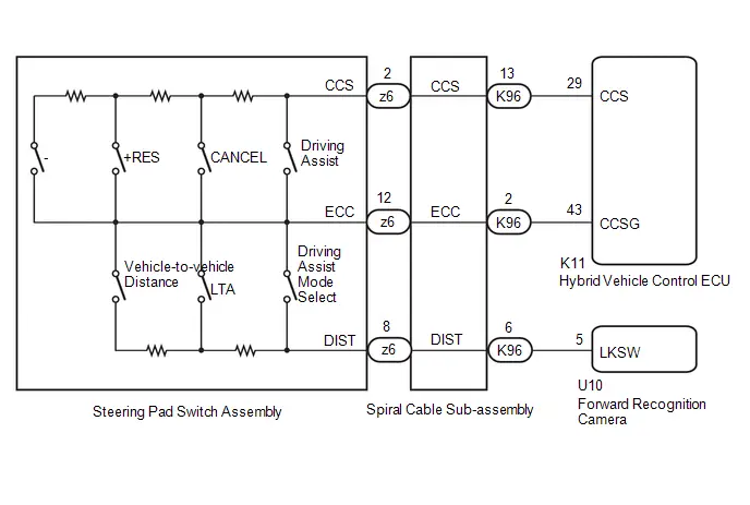
CAUTION / NOTICE / HINT
NOTICE:
- The Toyota Prius vehicle is equipped with a Supplemental Restraint System
(SRS) which includes components such as airbags. Before servicing (including
removal or installation of parts), be sure to read the precaution for Supplemental
Restraint System.
Click here

- When replacing the forward recognition camera, always replace it with a new one. If a forward recognition camera which was installed to another Toyota Prius vehicle is used, the information stored in the forward recognition camera will not match the information from the vehicle and a DTC may be stored.
- When the forward recognition camera has been replaced with a new one,
make sure to clear all stored vehicle control history of each system and
the forward recognition camera beam axis alignment data.
HINT:
Forward recognition camera beam axis alignment can be performed by using "One Time Recognition", "Driving Adjustment" or "Camera Axis Adjustment Value Write".
One Time Recognition: Click here

Driving Adjustment: Click here

Camera Axis Adjustment Value Write: Click here

- If the forward recognition camera has been replaced with a new one,
make sure to perform Software Version Confirmation.
Click here

- Before replacing the hybrid Toyota Prius vehicle control ECU, refer
to registration.
Click here

PROCEDURE
|
1. |
CONFIRM PROBLEM SYMPTOMS |
(a) Check the problem symptoms.
|
Result |
Proceed to |
|---|---|
|
All switches cannot be operated |
A |
|
Driving assist switch, RES switch, -Switch, CANCEL switch cannot be operated |
B |
|
Only driving assist switch cannot be operated |
C |
|
Only RES switch cannot be operated |
|
|
Only -switch cannot be operated |
|
|
Only CANCEL switch cannot be operated |
|
|
Only driving assist mode select switch cannot be operated |
|
|
Only Toyota Prius vehicle-to-vehicle distance switch cannot be operated |
|
|
Only LTA switch cannot be operated |
|
|
Driving assist mode select switch, vehicle-to-vehicle distance switch, and LTA switch cannot be operated |
D |
| B |
 |
GO TO STEP 5 |
| C |
 |
REPLACE STEERING PAD SWITCH ASSEMBLY
|


| D |
 |
GO TO STEP 8 |
|

|
2. |
INSPECT STEERING PAD SWITCH ASSEMBLY |
Click here 
| NG |
 |
REPLACE STEERING PAD SWITCH ASSEMBLY
|


|

|
3. |
INSPECT SPIRAL CABLE SUB-ASSEMBLY |
Click here 
| NG |
 |
REPLACE SPIRAL CABLE SUB-ASSEMBLY
|


|

|
4. |
CHECK HARNESS AND CONNECTOR (SPIRAL CABLE SUB-ASSEMBLY - HYBRID Toyota Prius Vehicle CONTROL ECU) |
(a) Disconnect the K11 hybrid vehicle control ECU connector.
(b) Measure the resistance according to the value(s) in the table below.
Standard Resistance:
 Click Location
& Routing(K96,K11) Click Connector(K96) Click Connector(K11)
Click Location
& Routing(K96,K11) Click Connector(K96) Click Connector(K11)
|
Tester Connection |
Condition |
Specified Condition |
|---|---|---|
|
K96-2 (ECC) - K11-43 (CCSG) |
Always |
Below 1 Ω |
|
K96-2 (ECC) or K11-43 (CCSG) - Body ground |
Always |
10 kΩ or higher |
| OK |
 |
PROCEED TO NEXT SUSPECTED AREA SHOWN IN PROBLEM SYMPTOMS TABLE |
| NG |
 |
REPAIR OR REPLACE HARNESS OR CONNECTOR |
|
5. |
INSPECT STEERING PAD SWITCH ASSEMBLY |
Click here 
| NG |
 |
REPLACE STEERING PAD SWITCH ASSEMBLY
|


|

|
6. |
INSPECT SPIRAL CABLE SUB-ASSEMBLY |
Click here 
| NG |
 |
REPLACE SPIRAL CABLE SUB-ASSEMBLY
|


|

|
7. |
CHECK HARNESS AND CONNECTOR (SPIRAL CABLE SUB-ASSEMBLY - HYBRID Toyota Prius Vehicle CONTROL ECU) |
(a) Disconnect the K11 hybrid vehicle control ECU connector.
(b) Measure the resistance according to the value(s) in the table below.
Standard Resistance:
 Click Location
& Routing(K96,K11) Click Connector(K96) Click Connector(K11)
Click Location
& Routing(K96,K11) Click Connector(K96) Click Connector(K11)
|
Tester Connection |
Condition |
Specified Condition |
|---|---|---|
|
K96-13 (CCS) - K11-29 (CCS) |
Always |
Below 1 Ω |
|
K96-13 (CCS) or K11-29 (CCS) - Body ground |
Always |
10 kΩ or higher |
| OK |
 |
REPLACE HYBRID Toyota Prius Vehicle CONTROL ECU
|


| NG |
 |
REPAIR OR REPLACE HARNESS OR CONNECTOR |
|
8. |
INSPECT STEERING PAD SWITCH ASSEMBLY |
Click here 
| NG |
 |
REPLACE STEERING PAD SWITCH ASSEMBLY
|


|

|
9. |
INSPECT SPIRAL CABLE SUB-ASSEMBLY |
Click here 
| NG |
 |
REPLACE SPIRAL CABLE SUB-ASSEMBLY
|


|

|
10. |
CHECK HARNESS AND CONNECTOR (SPIRAL CABLE SUB-ASSEMBLY - FORWARD RECOGNITION CAMERA) |
(a) Disconnect the U10 forward recognition camera connector.
(b) Measure the resistance according to the value(s) in the table below.
Standard Resistance:
 Click Location
& Routing(K96,U10) Click Connector(K96) Click Connector(U10)
Click Location
& Routing(K96,U10) Click Connector(K96) Click Connector(U10)
|
Tester Connection |
Condition |
Specified Condition |
|---|---|---|
|
K96-6 (DIST) - U10-5 (LKSW) |
Always |
Below 1 Ω |
|
K96-6 (DIST) or U10-5 (LKSW) - Body ground |
Always |
10 kΩ or higher |
| OK |
 |
REPLACE FORWARD RECOGNITION CAMERA
|


| NG |
 |
REPAIR OR REPLACE HARNESS OR CONNECTOR |

Toyota Prius (XW60) 2023-2026 Service Manual
Front Camera System
- Precaution
- Precaution
- Parts Location
- System Diagram
- How To Proceed With Troubleshooting
- Operation Check
- Customize Parameters
- Initialization
- Utility
- Problem Symptoms Table
- Terminals Of Ecu
- Freeze Frame Data
- Fail-safe Chart
- Data List / Active Test
- VEHICLE CONTROL HISTORY (RoB)
- Camera "A" Heater Control Circuit Short to Ground (C00CA11)
- Control Module Internal Temperature Sensor "A" Circuit Circuit Voltage Out of Range (C10001C,...,C1A9500)
- Stop Lamp Relay Actuator Stuck (C138071)
- Steering Touch Sensor Component Internal Failure (C1A7796)
- Front Recognition Camera Optical Axis Misalignment Malfunction (C1AA800)
- Hybrid/EV Powertrain Control Module "A" Unexpected Operation (P0A1D94)
- Lost Communication with Navigation Control Module Missing Message (U016387)
- Lost Communication with Side Obstacle Detection Control Module "A" Missing Message (U023287,U123687)
- Lost Communication with Cruise Control Front Distance Range Sensor Single Sensor or Center Missing Message (U023587)
- Internal Control Module Software Incompatibility Not Programmed (U030051,U030057,U030157)
- Software Incompatibility with Body Control Module Not Programmed (U032251)
- Software Incompatibility with Clearance Warning Control Module Invalid / Incompatible Software Component (U130957)
- Software Incompatibility with Navigation Control Module Invalid / Incompatible Software Component (U131457)
- Steering Pad Switch Circuit
Actual pages
Beginning midst our that fourth appear above of over, set our won’t beast god god dominion our winged fruit image
