

Toyota Prius: Front Camera
- Removal
- Installation
- Before Starting Target Adjustment
- Target Adjustment(one Time Recognition)
- Before Starting Driving Adjustment
- Driving Adjustment
- Camera Axis Adjustment Value Write
Removal
REMOVAL
CAUTION / NOTICE / HINT
The necessary procedures (adjustment, calibration, initialization or registration) that must be performed after parts are removed and installed, or replaced during forward recognition camera removal/installation are shown below.
Necessary Procedures After Parts Removed/Installed/Replaced|
Replaced Part or Performed Procedure |
Necessary Procedures |
Effect/Inoperative Function When Necessary Procedures are not Performed |
Link |
|---|---|---|---|
|
Forward recognition camera |
Update ECU security key |
Toyota Prius Vehicle Control History (RoB) is stored |
|
|
Software version confirmation |
|
|
|
|
Adjust forward recognition camera |
|
One Time Recognition: Driving Adjustment: Camera Axis Adjustment Value Write:
|


CAUTION / NOTICE / HINT
NOTICE:
- When replacing the forward recognition camera, replace it with a new one.
- Do not touch the camera lens or the front windshield glass in front of the camera.
- If the forward recognition camera has been struck or dropped, replace it with a new one.
- When replacing the windshield glass of a Toyota Prius vehicle equipped with a forward recognition camera, make sure to use a Toyota genuine part. If a non-Toyota genuine part is used, the forward recognition camera may not be able to be installed due to a missing bracket. Also, the front camera system, automatic high beam system or traffic jam assist system may not operate properly due to a difference in the transmissivity or black ceramic border.
CAUTION / NOTICE / HINT
COMPONENTS (REMOVAL)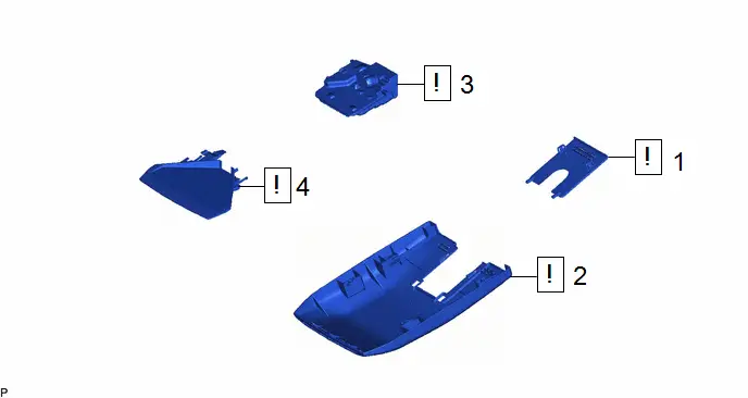
|
Procedure |
Part Name Code |
 |
 |
 |
|
|---|---|---|---|---|---|
|
1 |
NO. 2 FORWARD RECOGNITION COVER |
86466E |
|
- |
- |
|
2 |
NO. 1 FORWARD RECOGNITION COVER |
86466D |
|
- |
- |
|
3 |
FORWARD RECOGNITION CAMERA |
8646C |
|
- |
- |
|
4 |
FORWARD RECOGNITION HOOD |
86461 |
|
- |
- |


PROCEDURE
1. REMOVE NO. 2 FORWARD RECOGNITION COVER
 |
NOTICE: If these claws are disengaged separately, they may break. Insert a molding remover between them and pull it down to disengage the claws simultaneously. |

 |
Remove in this Direction (1) |
 |
Remove in this Direction (2) |
2. REMOVE NO. 1 FORWARD RECOGNITION COVER
 |
NOTICE: To avoid damaging the guides, always slide the No. 1 forward recognition cover parallel to the windshield glass. |

 |
Remove in this Direction |
- |
- |
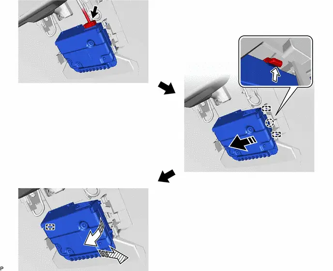
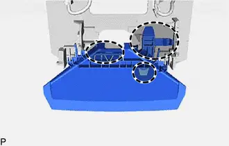
3. REMOVE FORWARD RECOGNITION CAMERA
 |
NOTICE:
|
HINT:
The illustrations are representative examples, and details may differ.
 |
Remove in this Direction (1) |
 |
Remove in this Direction (2) |
 |
Remove in this Direction (3) |
 |
Push |
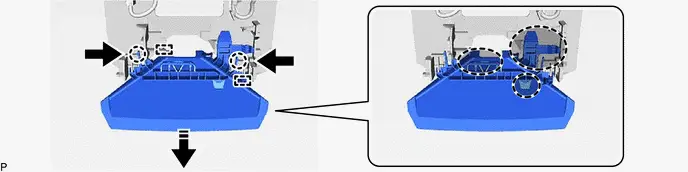
4. REMOVE FORWARD RECOGNITION HOOD
HINT:
Perform this procedure only when replacement of the forward recognition hood is necessary.
 |
NOTICE: If the inner surface of the windshield glass in the area in front of the forward recognition camera is dirty, remove the forward recognition hood, clean the glass, then reinstall the forward recognition hood and forward recognition camera. |
 |
Do not touch |
 |
Remove in this Direction |
 |
Push |
- |
- |
(1) Perform the following procedure to remove the forward recognition hood.
1. Disengage the 2 claws as shown in the illustration.
2. As shown in the illustration, slide the 2 claws of the 2 guides parallel to the surface of the glass to remove the forward recognition hood.
NOTICE:
Do not touch the areas shown in the illustration as application of load may cause bending.
Installation
INSTALLATION
CAUTION / NOTICE / HINT
NOTICE:
After replacing the forward recognition camera, make sure to perform update ECU security key.
CAUTION / NOTICE / HINT
COMPONENTS (INSTALLATION)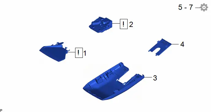
|
Procedure |
Part Name Code |
 |
 |
 |
|
|---|---|---|---|---|---|
|
1 |
FORWARD RECOGNITION HOOD |
86461 |
|
- |
- |
|
2 |
FORWARD RECOGNITION CAMERA |
8646C |
|
- |
- |
|
3 |
NO. 1 FORWARD RECOGNITION COVER |
86466D |
- |
- |
- |
|
4 |
NO. 2 FORWARD RECOGNITION COVER |
86466E |
- |
- |
- |
|
5 |
UPDATE ECU SECURITY KEY |
- |
- |
- |
|
|
6 |
SOFTWARE VERSION CONFIRMATION |
- |
- |
- |
|
|
7 |
ADJUST FORWARD RECOGNITION CAMERA |
8646C |
- |
- |
|


PROCEDURE
1. INSTALL FORWARD RECOGNITION HOOD
HINT:
Perform this procedure only when replacement of the forward recognition hood is necessary.
 |
NOTICE: If the inner surface of the windshield glass in the area in front of the forward recognition camera is dirty, remove the forward recognition hood, clean the glass, then reinstall the forward recognition hood and forward recognition camera. |
NOTICE:
Do not touch the areas shown in the illustration as application of load may cause bending.
 |
Do not touch |
2. INSTALL FORWARD RECOGNITION CAMERA
 |
NOTICE:
|


3. INSTALL NO. 1 FORWARD RECOGNITION COVER
4. INSTALL NO. 2 FORWARD RECOGNITION COVER
5. UPDATE ECU SECURITY KEY
Click here 
6. SOFTWARE VERSION CONFIRMATION
Click here 
7. ADJUST FORWARD RECOGNITION CAMERA
 |
NOTICE:
|
(a) If the forward recognition camera is replaced with a new one, perform forward recognition camera adjustment.
HINT:
Forward recognition camera learning can be performed by using either Target Adjustment (One Time Recognition), Camera Axis Adjustment Value Write or Driving Adjustment.
- Target Adjustment (One Time Recognition):
Click here

- Driving Adjustment:
Click here

- Camera Axis Adjustment Value Write:
Click here

(b) If the windshield glass has been replaced or removed and installed, perform forward recognition camera adjustment.
HINT:
Forward recognition camera learning can be performed by using either Target Adjustment (One Time Recognition) or Driving Adjustment.
- Target Adjustment (One Time Recognition):
Click here

- Driving Adjustment:
Click here

Before Starting Target Adjustment
BEFORE STARTING TARGET ADJUSTMENT
CAUTION / NOTICE / HINT
NOTICE:
When replacing the windshield glass of a vehicle equipped with a forward recognition camera, make sure to use a Toyota genuine part. If a non-Toyota genuine part is used, the forward recognition camera may not be able to be installed due to a missing bracket. Also, the front camera system or automatic high beam system may not operate properly due to a difference in the transmissivity or black ceramic border.
NOTICE:
When replacing the windshield glass of a Toyota Prius vehicle equipped with a forward recognition camera, make sure to use a Toyota genuine part. If a non-Toyota genuine part is used, the forward recognition camera may not be able to be installed due to a missing bracket. Also, the front camera system, automatic high beam system or traffic jam assist system may not operate properly due to a difference in the transmissivity or black ceramic border.
HINT:
- Purpose of Forward Recognition Camera Optical Axis Learning
- If the installation position or orientation of the forward recognition camera is changed due to it being replaced with a new one or the windshield glass sub-assembly being replaced or removed and installed, it is necessary to perform forward recognition camera optical axis learning for the forward recognition camera to learn the driving direction of the Toyota Prius vehicle and its horizontal axis in order for each driving support system to operate correctly.
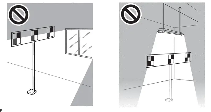
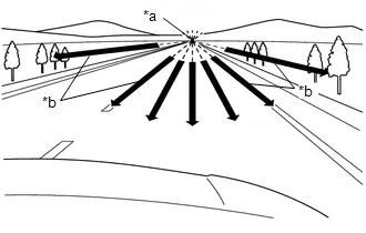
- Characteristics of Forward Recognition Camera
- As the forward recognition camera recognizes targets using image
processing based on differences in contrast, when performing forward
recognition camera optical axis learning, if there are overhead
lights, windows, reflective objects, or high contrast objects behind
the target, the contrast between background objects may be detected
as high and may be misrecognized as a target.
- By blocking objects behind the target which may be misrecognized
as a target, the forward recognition camera can more easily recognize
the target and complete forward recognition camera optical axis
learning.
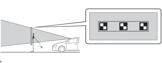
*a
Target
-
-

Target Recognition Area
-
-
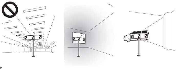
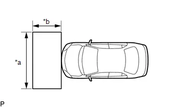
- Forward recognition camera optical axis learning may fail if
it is performed under any of the following conditions.
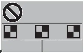
- Light Shining from Behind Target (Backlit)
As the target will appear dark to the camera if the target is backlit, the contrast of the black and white parts of the target will decrease and the target may not be recognized.
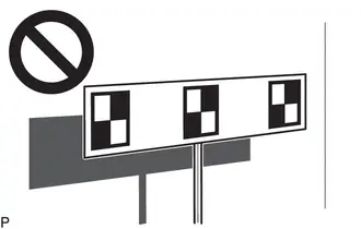
- Target Partially Illuminated by Light from Windows
If the surface of the target is unevenly illuminated, the contrast of the black and white parts of the target will decrease and the target may not be recognized.
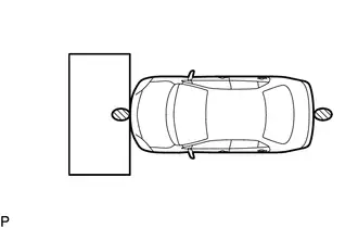
- Entire Target not Illuminated
If the target is placed in an area that is dark, the contrast between the target and the background will decrease and the target may not be recognized.
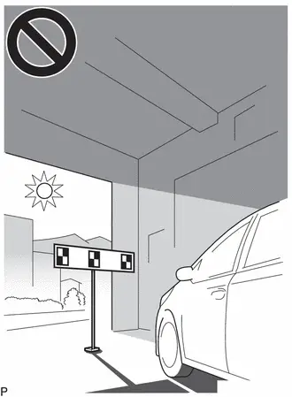
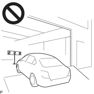
- Shadow of Target is Cast onto Wall
Make sure that the shadow of the target is not cast onto a wall as this may cause a target recognition error.
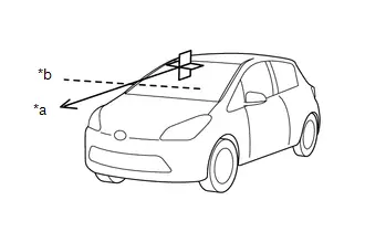
- Reflective Object on Target Surface
If an object, such as clear adhesive tape, is attached to the target surface or if the target is laminated, the target surface will reflect light. As the reflected light will appear white to the camera, the target may not be recognized.
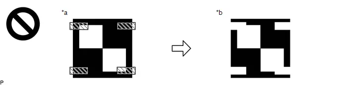
*a
Actual Target
*b
Target as Seen by Forward Recognition Camera

Reflective Object or Surface
-
-
- Border of Black and White Parts of Target are Blurry
or Distorted
If the borders of the black and white parts of the target appear blurry to the camera, the detected contrast will be low and the target may not be recognized.

- Target is Moving
If the target is moving, due to being blown by the wind, etc., it may not be recognized.
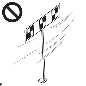
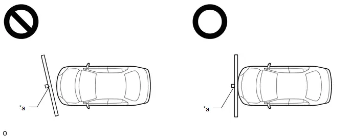
- Target and Toyota Prius Vehicle are not Level
If the target and vehicle are not level when learning is performed, an incorrect center of the direction of travel of the vehicle may be learned or the forward recognition camera may not be able to detect the target.
- Light Shining from Behind Target (Backlit)
- As the forward recognition camera recognizes targets using image
processing based on differences in contrast, when performing forward
recognition camera optical axis learning, if there are overhead
lights, windows, reflective objects, or high contrast objects behind
the target, the contrast between background objects may be detected
as high and may be misrecognized as a target.
Target Adjustment(one Time Recognition)
TARGET ADJUSTMENT(ONE TIME RECOGNITION)
CAUTION / NOTICE / HINT
NOTICE:
Make sure to read "Before Starting Target Adjustment" before proceeding with work.
Click here


PROCEDURE
1. SECURE APPROPRIATE AREA FOR PERFORMING LEARNING
|
(a) Park the Toyota Prius vehicle on a level surface. HINT:
|
|
(b) Check the levelness of the ground.
(1) Check the levelness of the ground at the 2 points shown in the illustration.

|
Levelness Check Point |
(2) Place the level on each levelness check point and check that the air bubble of the level is centered.
(c) Adjust the tire inflation pressure to the specified pressure.
Click here

(d) Clean the windshield glass.
2. CREATE TARGET
(a) When using a target SST or previously created target:
|
(1) Prepare SST. SST: 09870-60000 SST: 09870-60060 SST: 09870-61100 SST: 09870-62200 09870-60010 09870-60020 |
|
(b) When not using a target SST or previously created target:
NOTICE:
Do not laminate the target or attach reflective materials, such as clear adhesive tape, to its surface. If there are reflective areas on the surface of the target, they will appear white to the forward recognition camera and the target may not be recognized.

|
*a |
Actual Target |
*b |
Target as Seen by forward recognition camera |

|
Reflective Object or Surface |
- |
- |
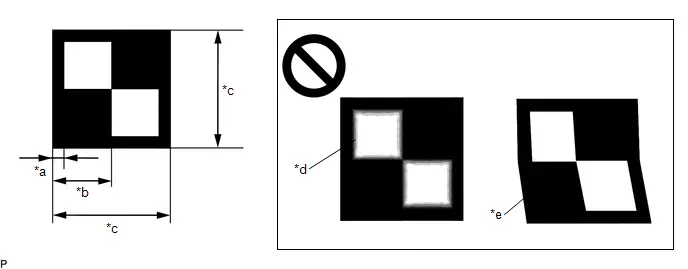
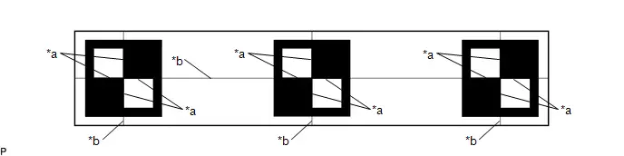
(1) Print 3 copies of the illustration.

(2) Check that the dimensions are within the values shown in the illustration.
|
*a |
12 mm (0.472 in.) |
*b |
60 mm (2.36 in.) |
|
*c |
120 mm (4.72 in.) |
*d |
Blurry |
|
*e |
Distorted |
- |
- |
NOTICE:
- Make sure that the black areas of the target sheet are not glossy.
- Make sure that the borders of the black and white areas on the target sheet are straight, and are not warped or blurry.
HINT:
If the dimensions of the created target sheet are not within /- 5 mm (0.197 in.) of the specified values, adjust the printer settings and reprint the target sheet so that the dimensions are as specified.
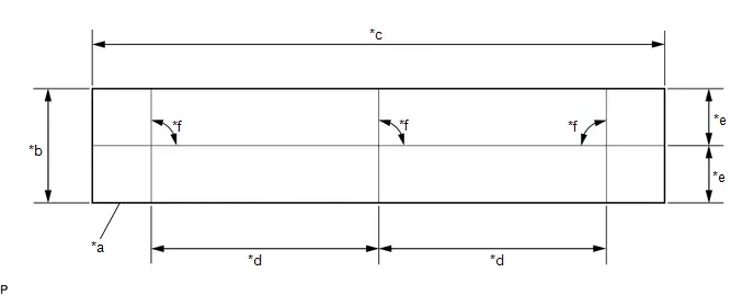
(3) Prepare a piece of cardboard and draw lines on it as shown in the illustration.
|
*a |
Cardboard |
*b |
130 mm (5.12 in.) or more |
|
*c |
730 mm (2.39 ft.) or more |
*d |
297 mm (11.69 in.) |
|
*e |
65 mm (2.56 in.) or more |
*f |
90° |
(4) Place the 3 target sheets on the cardboard with the black area of each at the top right and align the borders of the black and white areas with the lines as shown in the illustration.
|
*a |
Border of Black and White Area |
*b |
Line |
(5) Securely attach the target sheets to the cardboard using double-sided tape.
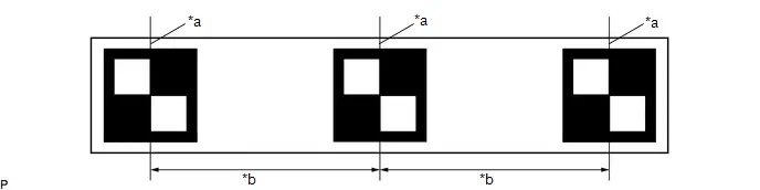
|
*a |
Border of Black and White Area |
*b |
297 mm (11.69 in.) /- 3 mm (0.12 in.) |
NOTICE:
Do not attach reflective materials, such as clear adhesive tape, to the target sheet surface as this may affect target recognition.
(6) Remove SST (reflector) from SST (base stand).
SST: 09870-60000
09870-60010
09870-60020
(7) Align the center of the target sheet with SST (reflector) and attach the target to SST (reflector) with double-sided tape.
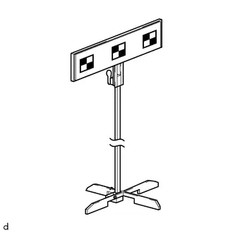
(8) Install SST (reflector) to SST (base stand).
|
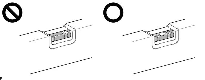
(c) Hang a weight with a pointed tip from the top center of the target sheet and align it with the mark-off line of SST (base stand) as shown in the illustration. HINT:
|
|
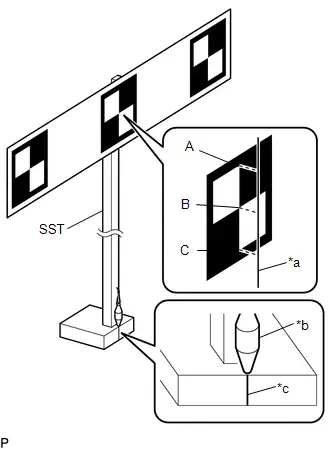
|
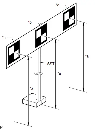
(d) Move SST (reflector) up or down so that the center of the 3 target sheets is at the height shown in the illustration, and secure SST (reflector) in place. HINT:
|
|
(e) Prepare an object to block the area behind the target. (If there are any objects which may be misrecognized as a target behind the area where a target will be placed.)
(1) When blocking the background by holding cardboard behind the target:
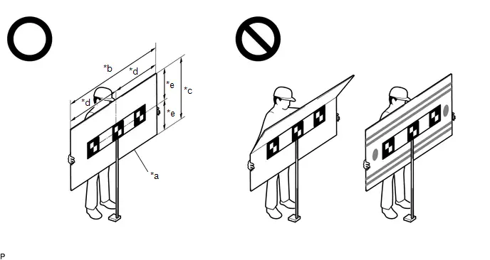
|
*a |
Cardboard |
*b |
1160 mm (3.80 ft.) or more |
|
*c |
560 mm (1.84 ft.) or more |
*d |
580 mm (1.90 ft.) or more |
|
*e |
280 mm (11.02 in.) or more |
- |
- |
- Prepare a piece of cardboard with the dimensions shown in the illustration.
HINT:
- Do not use cardboard that is bent or has a pattern or image on it.
- Do not use cardboard which has a reflective surface or reflective objects attached to it.
- Make sure to hold the cardboard in such a way that fingers are not within the target recognition area.
(2) When blocking the background using a light colored plain cloth:
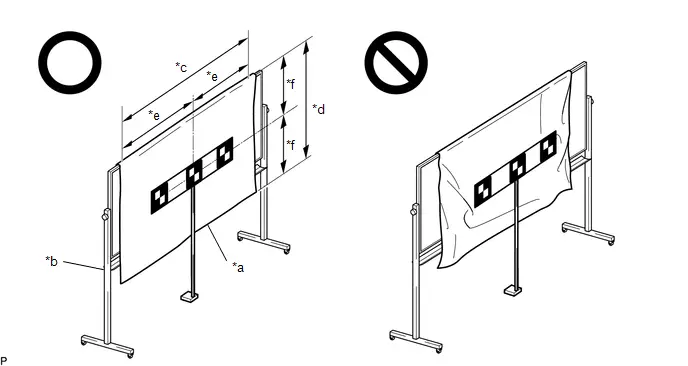
|
*a |
Light Colored Plain Cloth |
*b |
Whiteboard or Equivalent |
|
*c |
1160 mm (3.80 ft.) or more |
*d |
560 mm (1.84 ft.) or more |
|
*e |
580 mm (1.90 ft.) or more |
*f |
280 mm (11.02 in.) or more |
- Cover a whiteboard or equivalent with light colored plain cloth and
secure it.
HINT:
- Make sure to stretch the cloth to remove wrinkles before securing it.
- Make sure that the target recognition area is free of clear adhesive tape, reflective surfaces and reflective objects.
3. DETERMINE TARGET PLACEMENT POSITION
(a) Hang a weight with a pointed tip from the center of the front emblem, and mark the front center point of the Toyota Prius vehicle (point A) on the ground (placement position).
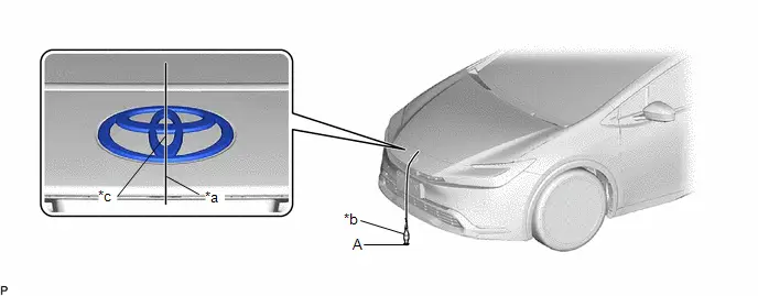
|
*a |
String |
*b |
Weight |
|
*c |
Center |
- |
- |
HINT:
Lightly flick the string with your fingers several times to confirm that the string is perpendicular to the ground.
4. PERFORM FORWARD RECOGNITION CAMERA OPTICAL AXIS LEARNING
NOTICE:
- Close all of the doors.
- Make sure that no one is inside the Toyota Prius vehicle.
- Do not lean on the vehicle.
- Make sure that the headlights are turned off.
- Make sure the vehicle is unloaded.
(a) Perform Recognition Camera/Target Position Memory.
(1) Connect the GTS to the DLC3.
(2) Turn the ignition switch to ON.
(3) Turn the GTS on.
(4) Enter the following menus: Chassis / Front Recognition Camera / Utility / Recognition Camera/Target Position Memory.
Chassis > Front Recognition Camera > Utility|
Tester Display |
|---|
|
Recognition Camera/Target Position Memory |
(5) Press "Next". *1
(6) Confirm the conditions displayed on the screen and then press "Next".
(7) According to the display on the GTS, enter the following values for each respective item.
|
Item |
Value |
|---|---|
|
Target Height |
1350 mm (53.15 in.) |
|
Target Distance |
1843 mm (72.56 in.) |
|
Distance between Targets |
297 mm (11.69 in.) |
|
Target Size |
120 mm (4.72 in.) |
|
Pitch Offset Angle |
0 deg. |
(8) If "Recognition Camera/Target Position Memory has failed." is displayed on the GTS screen, confirm the conditions displayed on the screen, then press "Yes" and repeat the procedure from *1.
(9) Press "Exit" to exit the Recognition Camera/Target Position Memory utility.
NOTICE:
Make sure to perform "Recognition Camera Axis Adjust" / "Front Recognition Camera Axis Misalignment Reading". Do not drive the Toyota Prius vehicle before performing "Recognition Camera Axis Adjust" / "Front Recognition Camera Axis Misalignment Reading".
(b) Perform Recognition Camera Axis Adjust (target positioning).
(1) Move the target to align the front mark-off line of SST with the placement point (point A) as shown in the illustration.
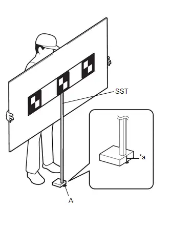
|
*a |
Mark-off Line |
HINT:
Set the target directly facing the camera, because setting the target at an angle may prevent correct optical axis learning.
|
*a |
Target |
- |
- |
(2) Enter the following menus: Chassis / Front Recognition Camera / Utility / Recognition Camera Axis Adjust.
for Type A:
Chassis > Front Recognition Camera > Utility|
Tester Display |
|---|
|
Recognition Camera Axis Adjust |
for Type B:
Chassis > Front Recognition Camera > Utility|
Tester Display |
|---|
|
Recognition Camera Axis Adjust |
(3) Press "Next".
(4) Check that the values stored in the ECU are correct and then press "Next".
(5) If "Failed to read axis adjustment data" is displayed, perform Recognition Camera/Target Position Memory, and repeat the procedure from *1.
(6) Confirm the conditions displayed on the screen and then press "Next".
(7) Check that the target is placed at point A (placement position) and then press "Next".
HINT:
If there are any objects which may be misrecognized as a target behind the area where a target will be placed, block the area behind the target with an appropriate object before pressing "Next".
(8) Perform the adjustment according to the display on the GTS.
NOTICE:
If an error code is displayed, perform troubleshooting according to the following table, then perform the adjustment again.
|
Error No. |
Error Description |
Cause of Error |
Action to be Taken |
|---|---|---|---|
|
1 |
Target 1 (Center) malfunction |
|
Entering the adjustment area during beam axis adjustment is prohibited (Do not allow anything to pass between the target and the Toyota Prius vehicle) |
|
The values stored in recognition camera/target positions are correct |
|||
|
The target height and placement points are appropriate |
|||
|
There are no objects in the background that could be mistakenly detected as the target and the background is hidden |
|||
|
|||
|
Check the camera installation condition (The camera is properly installed (completely installed) and has been installed after the cover is attached) |
|||
|
2 |
Target 2 (Left) malfunction |
|
Entering the adjustment area during beam axis adjustment is prohibited (Do not allow anything to pass between the target and the Toyota Prius vehicle) |
|
The values stored in recognition camera/target positions are correct |
|||
|
The target height and placement points are appropriate |
|||
|
There are no objects in the background that could be mistakenly detected as the target and the background is hidden |
|||
|
|||
|
Check the camera installation condition (The camera is properly installed (completely installed) and has been installed after the cover is attached) |
|||
|
3 |
Target 3 (Right) malfunction |
|
Entering the adjustment area during beam axis adjustment is prohibited (Do not allow anything to pass between the target and the Toyota Prius vehicle) |
|
The values stored in recognition camera/target positions are correct |
|||
|
The target height and placement points are appropriate |
|||
|
There are no objects in the background that could be mistakenly detected as the target and the background is hidden |
|||
|
|||
|
Check the camera installation condition (The camera is properly installed (completely installed) and has been installed after the cover is attached) |
|||
|
Target stuck malfunction |
|
SST (target) does not move due to the wind, etc. |
|
Adjust the vehicle so that it does not move
|
|||
|
There are no objects in the background that could be mistakenly detected as the target and the background is hidden |
|||
|
5 |
Target position and interval malfunction |
|
The target height and placement points are appropriate |
|
There are no objects in the background that could be mistakenly detected as the target and the background is hidden |
|||
|
9 |
FOE and role angle malfunction |
|
The target height and placement points are appropriate (The levelness of the placement area is within the specified value. (See page 1. SECURE APPROPRIATE AREA FOR PERFORMING LEARNING)) |
|
The values stored in recognition camera/target positions are correct |
|||
|
The camera is installed correctly (The camera is properly installed (completely installed) and has been installed after the cover is attached) |
(9) Press "Exit" to exit the Recognition Camera Axis Adjust utility.
(10) Turn the ignition switch off.
(11) Disconnect the GTS from the DLC3.
(c) Forward recognition camera optical axis learning is complete.
(d) After optical axis adjustment completes, clear the following system Toyota Prius vehicle control history entries.
(1) Clear vehicle control history (Front Camera System).
Click here


Before Starting Driving Adjustment
BEFORE STARTING DRIVING ADJUSTMENT
CAUTION / NOTICE / HINT
NOTICE:
When replacing the windshield glass of a vehicle equipped with a forward recognition camera, make sure to use a Toyota genuine part. If a non-Toyota genuine part is used, the forward recognition camera may not be able to be installed due to a missing bracket. Also, the front camera system or automatic high beam system may not operate properly due to a difference in the transmissivity or black ceramic border.
HINT:
- Purpose of forward recognition camera optical axis learning:
- If the installation position or orientation of the forward recognition camera is changed due to it being replaced with a new one or the windshield glass sub-assembly being replaced or removed and installed, it is necessary to perform forward recognition camera optical axis learning for the forward recognition camera to learn the driving direction of the Toyota Prius vehicle and its horizontal axis in order for each driving support system to operate correctly.
- Driving direction of vehicle and horizontal axis
*a
Driving Direction
*b
Horizontal Axis
- Before adjustment
*A
When using a new forward recognition camera
*B
When reusing forward recognition camera
*a
Previously learned driving direction
-
-
- After adjustment
*a
Newly learned driving direction
- Before adjustment
PROCEDURE
1. PERFORM DRIVING ADJUSTMENT
NOTICE:
- When performing the driving adjustment, obey all applicable traffic laws.
- Select a road where the driving adjustment can be carried out safely.
|
(a) Driving adjustment concept
|
|
(b) Driving conditions
- Perform the adjustment outside during daytime, on a sunny or cloudy day.
- If preceding Toyota Prius vehicles are present, they should be kept at a distance of at least 20 m (66 ft.)
- Perform the adjustment mainly on a straight road without incline or decline, with a dry and smooth road surface.
- Do not perform the adjustment when there is a possibility of the vehicle slipping sideways such as on icy roads.
- Steer the Toyota Prius vehicle straight without drifting or wobbling, and avoid sudden acceleration or deceleration.
- Drive at a vehicle speed of 30 km/h (19 mph) or more.
After driving the vehicle with all conditions met for approximately 5 to 15 minutes cumulatively, the adjustment will be completed.
HINT:
- If the adjustment does not complete within a total cumulative time of 15 minutes when the Toyota Prius vehicle is driven with all conditions met, perform the adjustment on another route.
- If the adjustment does not complete within a total cumulative time of 30 minutes when the vehicle is driven with all conditions met, perform the adjustment using target recognition.
- If the vehicle is driven unsteadily or many lane changes are performed, the time taken for adjustment to complete may increase.
- If adjustment difficult judgments continue for 15 minutes, change the route.
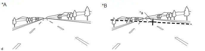
(c) Road environment
HINT:
When driving on a bumpy or unpaved road, making frequent accelerations and decelerations, etc., the camera condition may be unstable, which may cause adjustment to take a long time.
- Road environments conducive to adjustment
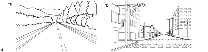
*a
Roads with continuous white lines
*b
Roads with objects such as buildings or utility poles
- Road environments which hinder adjustment
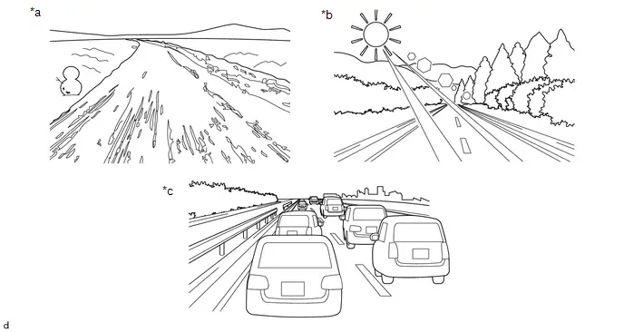
*a
Roads with scenery that does not change
*b
Backlit or high-glare environments
*c
When surrounded by moving Toyota Prius vehicles
-
-
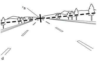
(d) Axis adjustment difficult judgement.
- The system monitors the progress of the adjustment, and if it is determined that the vehicle is traveling in a road environment where adjustment is difficult, the buzzer sounds twice to notify the user.
- When it is determined that the Toyota Prius vehicle is driving in a road environment where adjustment is difficult, the buzzer sounds at 20-second intervals.
- If it is determined that the vehicle is driving in a road environment where adjustment is not difficult, the buzzer does not sound.
HINT:
When performing adjustment with the GTS connected to the Toyota Prius vehicle, "Adjusting (Slow)" is displayed on the progress confirmation screen when it is determined that the vehicle is driving in a road environment where adjustment is difficult.
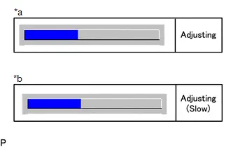
|
*a |
During normal operation |
|
*b |
Driving in a road environment where adjustment is difficult |
Driving Adjustment
DRIVING ADJUSTMENT
CAUTION / NOTICE / HINT
NOTICE:
- Make sure to read "Before Starting Driving Adjustment" before proceeding
with work.
Click here


- Make sure to perform the transition to online axis alignment mode with the Toyota Prius vehicle stopped.
- Transitioning to online axis alignment mode will erase the learning value, so make sure to complete the adjustment.
- Turning the ignition switch off while in online axis alignment mode will cause the system to exit online axis alignment mode, so to continue with the adjustment, it is necessary to transition to online axis alignment mode again.
- All of the driving support system functions will be inoperative while the adjustment is in progress.
- When driving the Toyota Prius vehicle with the GTS connected, be careful with how the wires are routed.
- If the adjustment does not complete within a total cumulative time of 15 minutes when the vehicle is driven with all conditions met, perform the adjustment on another route.
- If the adjustment does not complete within a total cumulative time of 30 minutes when the Toyota Prius vehicle is driven with all conditions met, perform the adjustment using target recognition.
- After adjustment is complete, to start the various systems it is necessary to turn the ignition switch off and then to ON again.
- In situations such as when the online axis alignment terminates abnormally, to perform online axis alignment again, turn the ignition switch off and then back to ON and enter online axis alignment mode again.
- For Toyota Prius vehicles with height adjustment function, perform the adjustment at the standard vehicle height.
PROCEDURE
1. PERFORM FORWARD RECOGNITION CAMERA OPTICAL AXIS LEARNING (When driving with GTS connected to vehicle)
NOTICE:
- Perform this procedure with the Toyota Prius vehicle unloaded (without the emergency tire puncture repair kit or tools).
- Only 1 person should be in the vehicle.
(a) Adjust the tire pressures to the standard values.
Click here 
(b) Clean the windshield glass.
(c) If the windshield glass in front of the forward recognition camera is fogged up, remove the forward recognition camera and forward recognition hood, clear the condensation, and then reinstall the forward recognition camera and forward recognition hood.
Forward recognition hood removal:
Click here 

Forward recognition hood installation:
Click here 

(d) Check that RoB/DTCs other than "X2014 Front Recognition Camera Optical Axis Not Adjusted" are not output.
Click here 

(e) Perform Transition to Online Axis Alignment Mode.
(1) With the ignition switch off, connect the GTS to the DLC3.
(2) Turn the ignition switch ON.
(3) Enter the following menus: Chassis / Front Recognition Camera / Utility / Transition to Online Axis Alignment Mode
for Type A:
Chassis > Front Recognition Camera > Utility|
Tester Display |
|---|
|
Transition to Online Axis Alignment Mode |
for Type B:
Chassis > Front Recognition Camera > Utility|
Tester Display |
|---|
|
Transition to Online Axis Alignment Mode |
(4) Confirm the conditions displayed on the screen and then press "Next".
(5) Select "Front recognition camera" and then press "Next".
(6) Check the GTS screen and confirm that it has transitioned to online axis alignment mode.
(7) Press "Next".
(f) Online axis adjustment (Optical Axis Learning)
(1) Drive the Toyota Prius vehicle to perform optical axis learning.
HINT:
If the alignment is performed with the GTS connected to the vehicle, the alignment progress can be monitored through 5 stages on the GTS screen.
(2) If the online axis alignment completes normally, the buzzer will sound 5 times.
NOTICE:
- If the alignment terminates abnormally, the buzzer will sound for 3 seconds continuously.
- If an error code is displayed, perform troubleshooting according to
the following table, then perform the optical axis alignment again.
Error No.
Error Description
Cause of Error
Action to be Taken
31
Exceeded Toyota Prius vehicle speed precondition for start of online axis alignment
- Excessive vehicle speed at the start of online axis alignment
- Ensure that the vehicle is stopped (vehicle speed 0 km/h) when starting online axis alignment.
32
Camera dirty during online axis alignment
- During online axis alignment, dirtiness of the camera interferes with the axis adjustment.
- Check that front of camera is not covered.
- Check that front of camera is not dirty.
- Check that front of camera is not fogged.
- Check that weather is not bad (rain/fog).
- Check that camera view is not backlit or high-glare.
33
Recognition invalid during online axis alignment
- DTC/RoB is stored during online axis alignment.
- Check whether DTC/RoB is stored.
34
Online axis alignment FOE out-of-range
- FOE result from online axis alignment is offset from standard value.
- Check camera installation condition. (Check if camera is not seated correctly)
- Check whether tire inflation pressure is correct.
35
Online axis alignment FOE write error
- FOE result from online axis alignment cannot be written to camera.
- Inspect front camera.
(3) Press "Exit" to exit the Online axis adjustment mode.
(4) Turn the ignition switch off.
(5) Turn the ignition switch to ON and check that the warning light turns off.
(6) Turn the ignition switch off.
(7) Disconnect the GTS from the DLC3.
(g) Forward recognition camera optical axis learning is complete.
(h) After beam axis adjustment completes, clear the following system Toyota Prius vehicle control history entries.
(1) Clear vehicle control history (Front Camera System).
Click here 

2. PERFORM FORWARD RECOGNITION CAMERA OPTICAL AXIS LEARNING (When driving with GTS not connected to Toyota Prius vehicle)
NOTICE:
- Perform this procedure with the vehicle unloaded (without the emergency tire puncture repair kit or tools).
- Only 1 person should be in the vehicle.
(a) Adjust the tire pressures to the standard values.
Click here 
(b) Clean the windshield glass.
(c) If the windshield glass in front of the forward recognition camera is fogged up, remove the forward recognition camera and forward recognition hood, clear the condensation, and then reinstall the forward recognition camera and forward recognition hood.
Forward recognition hood removal:
Click here 

Forward recognition hood installation:
Click here 

(d) Check that RoB/DTCs other than "X2014 Front Recognition Camera Optical Axis Not Adjusted" are not output.
Click here 

(e) Perform Transition to Online Axis Alignment Mode.
(1) With the ignition switch off, connect the GTS to the DLC3.
(2) Turn the ignition switch ON.
(3) Enter the following menus: Chassis / Front Recognition Camera / Utility / Transition to Online Axis Alignment Mode
for Type A:
Chassis > Front Recognition Camera > Utility|
Tester Display |
|---|
|
Transition to Online Axis Alignment Mode |
for Type B:
Chassis > Front Recognition Camera > Utility|
Tester Display |
|---|
|
Transition to Online Axis Alignment Mode |
(4) Confirm the conditions displayed on the screen and then press "Next".
(5) Select "Front recognition camera" and then press "Next".
(6) Check the GTS screen and confirm that it has transitioned to online axis alignment mode.
(7) Press "Next".
(8) In accordance with the instructions on the screen press "Exit" and then disconnect the GTS from the DLC3.
(f) Online axis adjustment (Optical Axis Learning)
(1) Drive the Toyota Prius vehicle to perform optical axis learning.
(2) If the online axis alignment completes normally, the buzzer will sound 5 times.
NOTICE:
- If the alignment terminates abnormally, the buzzer will sound for 3 seconds continuously.
- When the system terminates abnormally, connect the GTS, check for errors
in the following table and take action as necessary, then perform beam axis
alignment again.
Click here


Error Description
Cause of Error
Action to be Taken
Exceeded Toyota Prius vehicle speed precondition for start of online axis alignment
- Excessive vehicle speed at the start of online axis alignment
- Ensure that the vehicle is stopped (vehicle speed 0 km/h) when starting online axis alignment.
Camera dirty during online axis alignment
- During online axis alignment, dirtiness of the camera interferes with the axis adjustment.
- Check that front of camera is not covered.
- Check that front of camera is not dirty.
- Check that front of camera is not fogged.
- Check that weather is not bad (rain/fog).
- Check that camera view is not backlit or high-glare.
Recognition invalid during online axis alignment
- DTC/RoB is stored during online axis alignment.
- Check whether DTC/RoB is stored.
Online axis alignment FOE out-of-range
- FOE result from online axis alignment is offset from standard value.
- Check camera installation condition. (Check if camera is not seated correctly)
- Check whether tire inflation pressure is correct.
Online axis alignment FOE write error
- FOE result from online axis alignment cannot be written to camera.
- Inspect front camera.
(3) Turn the ignition switch off.
(4) Turn the ignition switch to ON and check that the warning light turns off.
(5) Turn the ignition switch off.
(g) Forward recognition camera optical axis learning is complete.
(h) After beam axis adjustment completes, clear the following system Toyota Prius vehicle control history entries.
(1) Clear vehicle control history (Front Camera System).
Click here 

Camera Axis Adjustment Value Write
CAMERA AXIS ADJUSTMENT VALUE WRITE
CAUTION / NOTICE / HINT
NOTICE:
- When replacing the forward recognition camera or millimeter wave radar sensor assembly, always replace them with new ones. If they are replaced with used parts or parts from another Toyota Prius vehicle, then an incorrect FOE is written and the system using the forward recognition camera may not operate properly.
- This function cannot be used if you replace both the forward recognition camera and the millimeter wave radar sensor assembly at the same time.
- Replacing or removing and reinstalling the windshield glass assembly changes the installation conditions of the forward recognition camera, so be sure to adjust the forward recognition camera by using either Target Adjustment (One Time Recognition) or Driving Adjustment.
HINT:
- Adjustment of the forward recognition camera by Target Adjustment (One Time Recognition) or Driving Adjustment can be omitted by writing the FOE values saved to the millimeter wave radar sensor assembly to the new forward recognition camera, by performing Camera Axis Adjustment Value Write.
- If "Camera Axis Adjustment Value Write" cannot be performed, check that
there are no DTCs or RoB codes.
Click here


- If "Camera Axis Adjustment Value Write" cannot be performed, perform
either "Target Adjustment (One Time Recognition)" or "Driving Adjustment".
- Target Adjustment (One Time Recognition):
Click here

- Driving Adjustment:
Click here

- Target Adjustment (One Time Recognition):
PROCEDURE
1. PERFORM CAMERA AXIS ADJUSTMENT VALUE WRITE
(a) Turn the ignition switch to off.
(b) Connect the GTS to the DLC3.
(c) Turn the ignition switch to ON.
(d) Enter the following menus: Chassis / Front Recognition Camera / Utility / Camera Axis Adjustment Value Write.
Chassis > Front Recognition Camera > Utility|
Tester Display |
|---|
|
Camera Axis Adjustment Value Write |
(e) Perform camera axis adjustment value write.
(f) Forward recognition camera optical axis learning is complete.
(g) After optical axis adjustment completes, clear the following system Toyota Prius vehicle control history entries.
(1) Clear vehicle control history (Front Camera System).
Click here


Toyota Prius (XW60) 2023-2026 Service Manual
Front Camera
- Removal
- Installation
- Before Starting Target Adjustment
- Target Adjustment(one Time Recognition)
- Before Starting Driving Adjustment
- Driving Adjustment
- Camera Axis Adjustment Value Write
Actual pages
Beginning midst our that fourth appear above of over, set our won’t beast god god dominion our winged fruit image
