

Toyota Prius: Front Radar Sensor System
- Precaution
- Parts Location
- System Diagram
- How To Proceed With Troubleshooting
- Utility
- Problem Symptoms Table
- Terminals Of Ecu
- Fail-safe Chart
- Data List / Active Test
- Diagnostic Trouble Code Chart
- VEHICLE CONTROL HISTORY (RoB)
- Front Radar Sensor Optical Axis Misalignment Malfunction (C1A1100)
- Main Microcomputer in Front Radar Sensor System Internal Failure (C1A8C04,C1A8C46,C1A8D1C,C1A9000)
- Lost Communication with Cruise Control Module Missing Message (U010487)
- Software Incompatibility with Image Processing Module "A" Not Programmed (U130C51,U130C57)
Precaution
PRECAUTION
PRECAUTIONS FOR DISCONNECTING CABLE FROM NEGATIVE (-) AUXILIARY BATTERY TERMINAL
NOTICE:
- After the ignition switch is turned off, there may be a waiting time
before disconnecting the negative (-) auxiliary battery terminal.
Click here

HINT:
When disconnecting and reconnecting the auxiliary battery, there is an automatic learning function that completes learning when the respective system is used.
Click here


PRECAUTIONS FOR FRONT RADAR SENSOR SYSTEM
(a) The millimeter wave radar sensor assembly may not be able to reliably detect the following objects:
- Pylons made from plastic, etc., glass surfaces such as the entrance to a convenience store, low to the ground objects such as curbs, etc.
- Persons or objects laying down
- Pedestrians, bicycles, motorcycles, trees, animals, walls, etc.
(b) The millimeter wave radar sensor assembly may not be able to detect obstacles or accurately measure the distance, angle or speed of obstacles in the following situations:
- When the preceding Toyota Prius vehicle or vehicles travelling in another lane splashes water or kicks up snow at the front of the vehicle
- When the rear end of the preceding vehicle is small (such as an empty trailer)
- When the posture of the vehicle has changed greatly due to modifications or overloading
- When raindrops or snow is stuck on the front of the sensor or on the front or back of the radar sensor cover
- When driving in bad weather (rain, fog, snow, sandstorms, etc.)
- When the front grille or radar sensor cover has been subjected to a strong impact
- When the radar sensor cover is damaged as a result of an impact, or the installation condition of the millimeter wave radar sensor assembly has changed
- When a Toyota Prius vehicle cuts closely in front of the vehicle, or when a two-wheeled vehicle is being driven close by
- When a non-genuine radar sensor cover is installed
- When an accessory, such as bull bars, a grille guard, etc., which interferes with millimeter radio waves is installed in front of the millimeter wave radar sensor assembly
- When the radar sensor cover and its surrounding area has been painted or is covered with a sticker
- When driving near a TV tower, broadcasting station, electric power plant, radar equipped Toyota Prius vehicles, etc., or other location where strong radio waves or electrical noise may be present
(c) The sensor may mistakenly detect signs over the road, structures such as traffic lights, ceilings of tunnels, steel plates on the road, high bridges, bridge seams, manholes, cat's eyes, gutters, bottles, cans, etc.
(d) The sensor may mistakenly detect Toyota Prius vehicles driving around curves nearby and vehicles driving in the distance as though they are driving in the same lane as the vehicle.
(e) The sensor may mistakenly detect or fail to detect objects when driving in an environment where there are many reflective objects around, such as a tunnel.
(f) The following objects may hinder the sensor's ability to detect objects. Therefore, always make sure that the radar sensor cover and the front of the millimeter wave radar sensor assembly are kept clean.
- Mud, insects, oil, etc.
- Snow
- Metal film (aluminum foil, candy wrappers that have a metallic coating, etc.)
PRECAUTIONS WHEN REPLACING MILLIMETER WAVE RADAR SENSOR ASSEMBLY
(a) Millimeter wave radar sensor assembly foreign matter, obstruction, and dirt detection function:
- The millimeter wave radar sensor assembly is equipped with a function to detect foreign matter, obstructions or dirt on the front of the sensor, however depending on conditions, foreign matter, obstructions, or dirt on the front surface of the sensor or on the front or rear surface of the radar sensor cover may not always be detected.
- The foreign matter, obstruction and dirt detection function may not operate if there is a metal object or metallic coated plastic bag tightly adhered to the sensor or cover.
- The foreign matter, obstruction and dirt detection function may not operate if ice or icicles are attached to the sensor or cover.
(b) Do not subject the millimeter wave radar sensor assembly or its surrounding area to strong impacts or excessive force. Do not disassemble the millimeter wave radar sensor assembly.
(c) Do not use a millimeter wave radar sensor assembly that has been dropped or subjected to a strong impact.
(d) When replacing the millimeter wave radar sensor assembly, try to avoid touching any part of it other than the mounting portions and the edges.
(e) If the bumper or front grille has been subjected to an impact, the system may not operate correctly due to damage to the millimeter wave radar sensor assembly or misalignment of the beam axis.
(f) To prevent incorrect operation, do not modify, paint, or replace the radar sensor cover or other parts around the millimeter wave radar sensor assembly.
(g) Do not attach stickers or accessories to the millimeter wave radar sensor assembly, the radar sensor cover or its surrounding area.
(h) Do not apply excessive force to the radar sensor cover or subject it to strong impacts.
(i) Before getting in the Toyota Prius vehicle, clear away any accumulated snow from the surface of the radar sensor cover.
(j) Before getting in the vehicle, clean away any foreign matter, obstructions, or dirt adhering to the surface of the radar sensor cover.
(k) Do not modify the vehicle in any way that would change its height or posture.
(l) Do not erase any printed characters marked on components.
REPLACEMENT PRECAUTIONS
(a) Millimeter wave radar sensor assembly:
(1) When replacing the millimeter wave radar sensor assembly, always replace it with a new one. If a millimeter wave radar sensor assembly which was installed to another Toyota Prius vehicle is used, the information stored in the millimeter wave radar sensor assembly will not match the information from the vehicle and a DTC may be stored.
(2) When the millimeter wave radar sensor assembly has been replaced with a new one, it is necessary to perform millimeter wave radar sensor assembly beam axis alignment and to clear the Toyota Prius vehicle control history. Before performing the Driving Adjustment, make sure to read Before Starting Driving Adjustment.
HINT:
Beam axis alignment of the millimeter wave radar sensor assembly can be performed using either Triangle Target, Flat Surface Target or Driving Adjustment.
Triangle Target: Click here 
Flat Surface Target: Click here

Driving Adjustment: Click here

(b) Forward recognition camera:
(1) When replacing the forward recognition camera, always replace it with a new one. If a forward recognition camera which was installed to another Toyota Prius vehicle is used, the information stored in the forward recognition camera will not match the information from the vehicle and a DTC may be stored.
(2) When the forward recognition camera has been replaced with a new one, make sure to clear all stored vehicle control history of each system and the forward recognition camera beam axis alignment data.
HINT:
Forward recognition camera beam axis alignment can be performed by using "One Time Recognition", "Driving Adjustment" or "Camera Axis Adjustment Value Write".
One Time Recognition: Click here

Driving Adjustment: Click here

Camera Axis Adjustment Value Write: Click here

(3) Do not damage the forward recognition camera lens or allow it to become dirty.
NOTICE:
If the forward recognition camera lens is touched, replace the forward recognition camera with a new one.
(4) Do not reuse a forward recognition camera that has been dropped or subjected to a strong impact.
(5) When the forward recognition camera is replaced, update the ECU security key.
Click here 
(6) If the forward recognition camera has been replaced with a new one, make sure to perform Software Version Confirmation.
Click here 
Parts Location
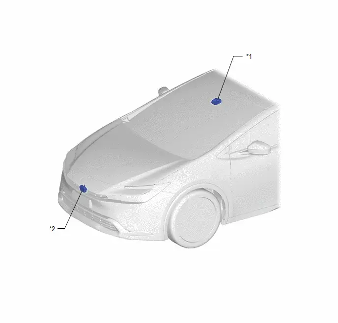
PARTS LOCATION
ILLUSTRATION
|
*1 |
FORWARD RECOGNITION CAMERA |
*2 |
MILLIMETER WAVE RADAR SENSOR ASSEMBLY |
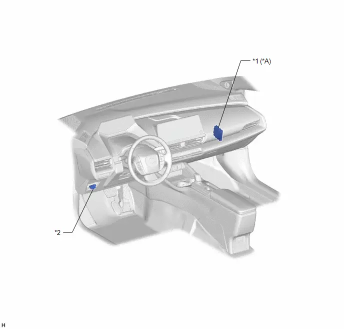
ILLUSTRATION
|
*A |
w/ Advanced Park |
- |
- |
|
*1 |
CLEARANCE WARNING ECU ASSEMBLY |
*2 |
DLC3 |
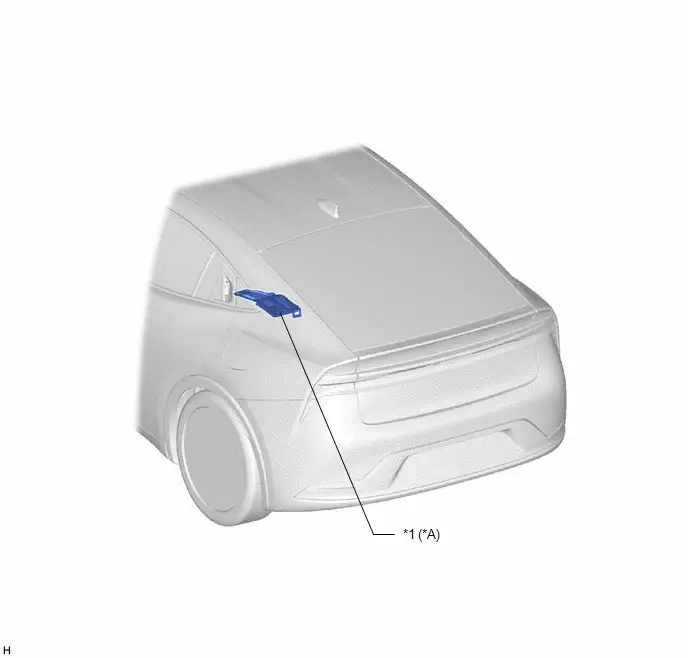
ILLUSTRATION
|
*A |
w/ Advanced Park |
- |
- |
|
*1 |
PARKING ASSIST ECU |
- |
- |
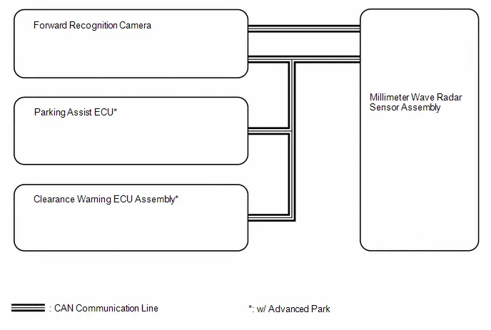
System Diagram
SYSTEM DIAGRAM
How To Proceed With Troubleshooting
CAUTION / NOTICE / HINT
HINT:
- Before performing troubleshooting for the front radar sensor system,
perform troubleshooting for the front camera system.
Click here

- *: Use the GTS.
PROCEDURE
|
1. |
Toyota Prius Vehicle BROUGHT TO WORKSHOP |
|

|
2. |
CUSTOMER PROBLEM ANALYSIS |
HINT:
- In troubleshooting, confirm that the problem symptoms have been accurately identified. Preconceptions should be discarded in order to make an accurate judgment. To clearly understand what the problem symptoms are, it is extremely important to ask the customer about the problem and the conditions at the time the malfunction occurred.
- Gather as much information as possible for reference. Past problems that seem unrelated may also help in some cases.
- The following 5 items are important points for problem analysis:
What
Toyota Prius Vehicle model, system name
When
Date, time, occurrence frequency
Where
Road conditions
Under what conditions?
Driving conditions, weather conditions
How did it happen?
Problem symptoms
|

|
3. |
PRE-CHECK |
(a) Measure the auxiliary battery voltage with the ignition switch off.
Standard voltage:
11 to 14 V
HINT:
If the voltage is below 11 V, recharge or replace the auxiliary battery before proceeding to the next step.
(b) Check the fuses and relays.
(c) Check the connector connections and terminals to make sure that there are no abnormalities such as loose connections, deformation, etc.
|

|
4. |
CHECK COMMUNICATION FUNCTION OF CAN COMMUNICATION SYSTEM* |
(a) Using the GTS, check for CAN communication system DTCs.
Click here

|
Result |
Proceed to |
|---|---|
|
CAN DTCs are not output |
A |
|
CAN DTCs are output |
B |
| B |

|
GO TO CAN COMMUNICATION SYSTEM |
|

|
5. |
CHECK FOR DTCs* |
(a) Using the GTS, check for DTCs.
Body Electrical > Front Radar Sensor > Trouble Codes|
Result |
Proceed to |
|---|---|
|
DTCs are not output |
A |
|
DTC C1A1100 is output |
B |
|
DTCs other than C1A1100 are output |
C |
| B |

|
GO TO DIAGNOSTIC TROUBLE CODE CHART (C1A1100) |
| C |

|
GO TO STEP 8 |
|

|
6. |
CHECK Toyota Prius Vehicle CONTROL HISTORY (RoB)* |
(a) Using the GTS, check for Vehicle Control History (RoB).
Body Electrical > Front Radar Sensor > Utility|
Tester Display |
|---|
|
Toyota Prius Vehicle Control History (RoB) |
(b) Make a note of the output Vehicle Control History (RoB).
|
Result |
Proceed to |
|---|---|
|
Toyota Prius Vehicle Control History (RoB) codes are not output |
A |
|
Vehicle Control History (RoB) code X2024, X2025, X2026 or X2028 is output |
B |
|
Toyota Prius Vehicle Control History (RoB) codes other than X2024, X2025, X2026 and X2028 are output |
C |
| A |

|
USE SIMULATION METHOD TO CHECK |
| B |

|
GO TO Toyota Prius Vehicle CONTROL HISTORY (RoB) (X2024, X2025, X2026 or X2028) |
|

|
7. |
RECONFIRM Toyota Prius Vehicle CONTROL HISTORY (RoB)* |
(a) Using the GTS, clear the Vehicle Control History (RoB).
Body Electrical > Front Radar Sensor > Utility|
Tester Display |
|---|
|
Toyota Prius Vehicle Control History (RoB) |
(b) Using the GTS, check for Vehicle Control History (RoB).
Body Electrical > Front Radar Sensor > Utility|
Tester Display |
|---|
|
Toyota Prius Vehicle Control History (RoB) |
|
Result |
Proceed to |
|---|---|
|
Vehicle Control History (RoB) codes are not output |
A |
|
Toyota Prius Vehicle Control History (RoB) codes are output |
B |
| A |

|
USE SIMULATION METHOD TO CHECK |
| B |

|
GO TO Toyota Prius Vehicle CONTROL HISTORY (RoB) |
|
8. |
RECONFIRM DTC OUTPUT* |
(a) Using the GTS, clear the DTCs.
Body Electrical > Front Radar Sensor > Clear DTCs(b) Reproduce the Toyota Prius vehicle conditions that were present when the DTCs that were noted were stored.
HINT:
Refer to each corresponding DTC for details on the detection conditions.
Click here

(c) Using the GTS, check for DTCs.
Body Electrical > Front Radar Sensor > Trouble Codes|
Result |
Proceed to |
|---|---|
|
DTCs are not output |
A |
|
DTCs are output |
B |
| A |

|
GO TO STEP 6 |
| B |

|
GO TO DIAGNOSTIC TROUBLE CODE CHART |
Utility
UTILITY
Transition to Online Axis Alignment Mode
NOTICE:
This utility transitions to online axis alignment mode of the millimeter wave radar sensor assembly.
(a) Following the instructions on the GTS, perform "Transition to Online Axis Alignment Mode".
Body Electrical > Front Radar Sensor > Utility|
Tester Display |
|---|
|
Transition to Online Axis Alignment Mode |
Front Beam Axis Adjustment
HINT:
Front Beam Axis Adjustment is used to calibrate the beam axis of millimeter wave radar sensor assembly.
(a) Perform Front Beam Axis Adjustment according to the display on the GTS.
Body Electrical > Front Radar Sensor > Utility|
Tester Display |
|---|
|
Front Beam Axis Adjustment |
Front Beam Axis Misalignment Reading
HINT:
Front Beam Axis Misalignment Reading is used to check the amount of misalignment of the millimeter wave radar sensor assembly.
(a) Perform Front Beam Axis Misalignment Reading according to the display on the GTS.
Body Electrical > Front Radar Sensor > Utility|
Tester Display |
|---|
|
Front Beam Axis Misalignment Reading |
Radio Wave Irradiation Stop Mode Cancellation
HINT:
Radio Wave Irradiation Stop Mode Cancellation is used to cancel the radio wave irradiation in the millimeter wave radar sensor assembly.
(a) Perform Radio Wave Irradiation Stop Mode Cancellation according to the display on the GTS.
Body Electrical > Front Radar Sensor > Utility|
Tester Display |
|---|
|
Radio Wave Irradiation Stop Mode Cancellation |
Problem Symptoms Table
PROBLEM SYMPTOMS TABLE
HINT:
- Use the table below to help determine the cause of problem symptoms. If multiple suspected areas are listed, the potential causes of the symptoms are listed in order of probability in the "Suspected Area" column of the table. Check each symptom by checking the suspected areas in the order they are listed. Replace parts as necessary.
- Inspect the fuses and relays related to this system before inspecting the suspected areas below.
|
Symptom |
Suspected Area |
Link |
|---|---|---|
|
"System Stopped See Owner's Manual" is displayed |
Toyota Prius Vehicle Control History (RoB) |
|
|
"System Malfunction Visit Your Dealer" is displayed |
Toyota Prius Vehicle Control History (RoB) |
|
|
"System Stopped Front Radar Sensor Blocked Clean Radar Sensor" is displayed |
Toyota Prius Vehicle Control History (RoB) |
|
|
"System Stopped Front Radar Sensor Out of Temperature Range Wait until Normal Temperature" is displayed |
Toyota Prius Vehicle Control History (RoB) |
|
|
"System Stopped Front Radar In Self Calibration See Owner's Manual" is displayed |
Toyota Prius Vehicle Control History (RoB) |
|


Terminals Of Ecu
TERMINALS OF ECU
NOTICE:
- DTCs may be output when connectors are disconnected during inspection. Therefore, be sure to clear the DTCs using the GTS once the inspection has been completed.
- Do not apply excessive force to the millimeter wave radar sensor assembly connector.
CHECK MILLIMETER WAVE RADAR SENSOR ASSEMBLY

(a) Measure the voltage and resistance according to the value(s) in the table below.
|
Terminal No. (Symbol) |
Terminal Description |
Condition |
Specified Condition |
|---|---|---|---|
|
A21-1 (IGB) - A21-5 (SGND) |
Power source |
Ignition switch ON |
11 to 14 V |
|
Ignition switch off |
Below 1 V |
||
|
A21-3 (CA2L) |
CAN communication signal |
- |
- |
|
A21-4 (CA2H) |
CAN communication signal |
- |
- |
|
A21-5 (SGND) - Body ground |
Ground |
Always |
Below 1 Ω |
|
A21-7 (CA1N) |
CAN communication signal |
- |
- |
|
A21-8 (CA1P) |
CAN communication signal |
- |
- |
|
A21-9 (CA3L) |
CAN communication signal |
- |
- |
|
A21-10 (CA3H) |
CAN communication signal |
- |
- |
Fail-safe Chart
FAIL-SAFE CHART
FAIL-SAFE FUNCTION
(a) If a malfunction is detected in the front radar sensor system, a message is displayed on the multi-information display and systems related to the malfunction are stopped.
Data List / Active Test
DATA LIST / ACTIVE TEST
DATA LIST
NOTICE:
In the table below, the values listed under "Normal Condition" are reference values. Do not depend solely on these reference values when deciding whether a part is faulty or not.
HINT:
Using the GTS to read the Data List allows the values or states of switches, sensors, actuators and other items to be read without removing any parts. This non-intrusive inspection can be very useful because intermittent conditions or signals may be discovered before parts or wiring is disturbed. Reading the Data List information early in troubleshooting is one way to save diagnostic time.
(a) Read the Data List according to the display on the GTS.
Body Electrical > Front Radar Sensor > Data List|
Tester Display |
Measurement Item |
Range |
Normal Condition |
Diagnostic Note |
|---|---|---|---|---|
|
Total Distance Traveled |
- |
- |
- |
Cannot be used |
|
Total Distance Traveled - Unit |
- |
- |
- |
Cannot be used |
|
Toyota Prius Vehicle Setting Value Delta X |
Sensor position |
-1.28 to 1.27 m |
Actual sensor position displayed |
- |
|
Toyota Prius Vehicle Setting Value Delta Z |
Sensor position |
0.00 to 655.35 m |
Actual sensor position displayed |
- |
|
Toyota Prius Vehicle Setting Value H |
Sensor position |
0.00 to 2.55 m |
Actual sensor position displayed |
- |
|
Radio Wave Irradiation Condition |
Status of radio wave irradiation |
Under Radio Wave Irradiation or Under Radio Wave Stopping |
Under Radio Wave Irradiation: Radio wave irradiation status displayed Under Radio Wave Stopping: Radio wave irradiation stop displayed |
- |
|
Optical Axis Not Adjusted Status |
Beam axis not adjusted status |
Complete or Not Complete |
Complete: Beam axis adjustment completed Not Complete: Beam axis adjustment not completed |
- |
|
Axis Adjustment Error Code |
Error code for axis alignment |
Normal or 0 to 31 |
Error code applicable for beam axis alignment |
- |
|
Optical Axis Adjustment Angle (Horizontal) (Latest) |
Latest beam axis adjustment angle value (horizontal) |
-12.8 to 12.7 deg |
Adjusted angle of beam axis alignment (Default value: 0.0 deg.) |
- |
|
Optical Axis Adjustment Angle (Vertical) (Latest) |
Latest beam axis adjustment angle value (vertical) |
-12.8 to 12.7 deg |
Adjusted angle of beam axis alignment (Default value: 0.0 deg.) |
- |
|
Optical Axis Adjustment Angle (Horizontal) (2nd Latest) |
2nd latest beam axis adjustment angle value (horizontal) |
-12.8 to 12.7 deg |
Adjusted angle of beam axis alignment (Default value: 0.0 deg.) |
- |
|
Optical Axis Adjustment Angle (Vertical) (2nd Latest) |
2nd latest beam axis adjustment angle value (vertical) |
-12.8 to 12.7 deg |
Adjusted angle of beam axis alignment (Default value: 0.0 deg.) |
- |
|
Optical Axis Offset Angle (Horizontal) |
Beam axis offset value (horizontal) |
-12.8 to 12.7 deg |
Beam axis offset value |
- |
|
Optical Axis Offset Angle (Vertical) |
Beam axis offset value (vertical) |
-12.8 to 12.7 deg |
Beam axis offset value |
- |
|
Optical Axis Offset Angle (Horizontal) (with On-Line Calibration Angle) |
Beam axis offset value (horizontal) (after completing calibration) |
-12.8 to 12.7 deg |
Beam axis offset value |
- |
|
Optical Axis Offset Angle (Vertical) (with On-Line Calibration Angle) |
Beam axis offset value (vertical) (after completing calibration) |
-12.8 to 12.7 deg |
Beam axis offset value |
- |
|
Dirt Detection for Radar Cruise |
Dirt detection status for radar cruise |
OFF or ON |
OFF: Dirt not detected ON: Dirt detected |
- |
|
Dirt Detection for PCS |
Dirt detection status for PCS |
OFF or ON |
OFF: Dirt not detected ON: Dirt detected |
- |
|
Partially Dirt Detection |
Partial dirt detection status |
OFF or ON |
OFF: Dirt not detected ON: Dirt detected |
- |
|
Foreign Matter Detection |
Foreign matter detection status |
OFF or ON |
OFF: No foreign matter detected ON: Foreign matter detected |
- |
|
Dirt Detection |
Dirt detection status |
OFF or ON |
OFF: Dirt not detected ON: Dirt detected |
- |
|
Blockage Detection |
Blockage detection status |
OFF or ON |
OFF: Blockage not detected ON: Blockage detected |
- |
|
Optical Axis Misalignment (Horizontal) |
Beam axis misalignment (horizontal) result |
OFF or ON |
OFF: Normal ON: Misalignment |
- |
|
Optical Axis Misalignment (Vertical) |
Beam axis misalignment (vertical) result |
OFF or ON |
OFF: Normal ON: Misalignment |
- |
|
Front Radar Sensor Temporary Unavailable (Horizontal Direction Optical Axis Misalignment) |
Millimeter wave radar sensor assembly temporarily unavailable due to horizontal beam axis misalignment |
OFF or ON |
OFF: Normal ON: Temporarily disabled due to beam axis misalignment |
- |
|
Front Radar Sensor Temporary Unavailable (Vertical Direction Optical Axis Misalignment) |
Millimeter wave radar sensor assembly temporarily unavailable due to vertical beam axis misalignment |
OFF or ON |
OFF: Normal ON: Temporarily disabled due to beam axis misalignment |
- |
|
IG Voltage |
IG voltage value |
0.0 to 25.5 V |
11.0 to 14.0 V: Ignition switch ON |
- |
|
Front Radar Sensor Temperature |
Temperature of area around millimeter wave radar sensor assembly |
-32768 to 32767°C |
Actual temperature of area around millimeter wave radar sensor displayed |
This value differs to the outside temperature. |
|
Toyota Prius Vehicle Speed |
Vehicle speed |
-30 km/h (-19 mph) to 225.99 km/h (159 mph) |
Almost same as actual vehicle speed |
- |
|
Ambient Temperature |
Actual ambient temperature |
-78.75 to 78.125°C |
Actual ambient temperature displayed |
- |
|
Wiper Operation Status |
Wiper operation status |
Front Wiper Stop, Front Wiper INT, Front Wiper LO, Front Wiper HI, Front Wiper Storage, Service Position or Front Wiper Malfunction |
Front wiper operation status displayed |
- |
|
Heater Control Duty |
Heater operation duty status of millimeter wave radar sensor assembly |
0 to 255 % |
Heater operation duty status of millimeter wave radar sensor assembly displayed |
Cannot be used |
|
Heater Control Status |
Heater operation status of millimeter wave radar sensor assembly |
OFF or ON |
OFF: Heater not operating ON: Heater operating |
Cannot be used |
|
On-Line Calibration Angle (Horizontal) |
Calibrated angle value (horizontal) |
-12.8 to 12.7 deg |
Learned value |
- |
|
On-Line Calibration Angle (Vertical) |
Calibrated angle value (vertical) |
-12.8 to 12.7 deg |
Learned value |
- |
Diagnostic Trouble Code Chart
DIAGNOSTIC TROUBLE CODE CHART
Front Radar Sensor System|
DTC No. |
Detection Item |
DTC Output from |
Priority |
Link |
|---|---|---|---|---|
|
C1A1100 |
Front Radar Sensor Optical Axis Misalignment Malfunction |
Front Radar Sensor |
A |
|
|
C1A8C04 |
Main Microcomputer in Front Radar Sensor System Internal Failure |
Front Radar Sensor |
A |
|
|
C1A8C46 |
Main Microcomputer in Front Radar Sensor Calibration/Parameter Memory Failure |
Front Radar Sensor |
A |
|
|
C1A8D1C |
Power Supply Circuit in Front Radar Sensor Circuit Voltage Out of Range |
Front Radar Sensor |
A |
|
|
C1A9000 |
Malfunction of Millimeter-wave Circuit in Front Radar Sensor |
Front Radar Sensor |
A |
|
|
U010487 |
Lost Communication with Cruise Control Module Missing Message |
Front Radar Sensor |
B |
|
|
U130C51 |
Software Incompatibility with Image Processing Module "A" Not Programmed |
Front Radar Sensor |
B |
|
|
U130C57 |
Software Incompatibility with Image Processing Module "A" Invalid/Incompatible Software Component |
Front Radar Sensor |
B |
|


VEHICLE CONTROL HISTORY (RoB)
VEHICLE CONTROL HISTORY (RoB)
NOTICE:
- Vehicle control history may be recorded due to the replacement or repair of related parts.
- When checking the Vehicle Control History, make sure to record the output codes. Then, clear the Vehicle Control History (RoB) and check it again.
CHECK Toyota Prius Vehicle CONTROL HISTORY (RoB) (FRONT RADAR SENSOR SYSTEM)
(a) Read the Vehicle Control History (RoB) according to the display on the GTS.
Body Electrical > Front Radar Sensor > Utility|
Tester Display |
|---|
|
Toyota Prius Vehicle Control History (RoB) |
|
Multi-information Display |
Code |
Tester Display |
Description |
Diagnostic Note |
|---|---|---|---|---|
|
System Malfunction Visit Your Dealer |
X2023 |
Front Radar Sensor Optical Axis Not Adjusted |
History of millimeter wave radar sensor assembly beam axis not being adjusted. |
If this Toyota Prius Vehicle Control History code is stored, clear the Vehicle Control History (RoB) after performing front beam axis adjustment, and then check that this code is not output again. HINT: Beam axis alignment of the millimeter wave radar sensor assembly can be performed using either Triangle Target, Flat Surface Target or Driving Adjustment. Triangle Target:
Flat Surface Target:
Driving Adjustment:
|
|
System Stopped Front Radar In Self Calibration See Owner's Manual |
X2024 |
Front Radar Sensor Temporary Unavailable (Vertical Direction Optical Axis Misalignment) |
History of millimeter wave radar sensor assembly beam axis misalignment (vertical). |
If this Toyota Prius Vehicle Control History code is stored, clear the Vehicle Control History (RoB) after performing front beam axis adjustment, and then check that this code is not output again. HINT: Beam axis alignment of the millimeter wave radar sensor assembly can be performed using either Triangle Target, Flat Surface Target or Driving Adjustment. Triangle Target:
Flat Surface Target:
Driving Adjustment:
|
|
System Stopped Front Radar In Self Calibration See Owner's Manual |
X2025 |
Front Radar Sensor Temporary Unavailable (Horizontal Direction Optical Axis Misalignment) |
History of millimeter wave radar sensor assembly beam axis misalignment (horizontal). |
If this Toyota Prius Vehicle Control History code is stored, clear the Vehicle Control History (RoB) after performing front beam axis adjustment, and then check that this code is not output again. HINT: Beam axis alignment of the millimeter wave radar sensor assembly can be performed using either Triangle Target, Flat Surface Target or Driving Adjustment. Triangle Target:
Flat Surface Target:
Driving Adjustment:
|
|
System Stopped Front Radar Sensor Blocked Clean Radar Sensor |
X2026 |
Front Radar Sensor Dirt |
History of system operation being temporarily suspended due to the millimeter wave radar sensor assembly not being able to detect objects. |
Cause:
|
|
System Stopped Front Radar Sensor Out of Temperature Range Wait until Normal Temperature |
X2027 |
Front Radar Sensor Outside Guaranteed Operating Temperature |
History of system operation being temporarily suspended due to the millimeter wave radar sensor assembly being excessively hot or cold. |
Cause:
|
|
System Stopped See Owner's Manual |
X2028 |
Front Radar Sensor Outside Guaranteed Operating Voltage |
History of system operation being temporarily suspended due to millimeter wave radar sensor assembly power source voltage being excessively high or low. |
Cause:
|
|
- |
X2076 |
Wiper Malfunction |
The millimeter wave radar sensor assembly received a wiper system malfunction signal from the main body ECU (multiplex network body ECU). |
Refer to How to Proceed with Troubleshooting in Wiper and Washer System.
|
|
- |
X2077 |
Ambient Temperature Sensor Circuit |
The millimeter wave radar sensor assembly received an ambient temperature sensor malfunction signal from the air conditioning amplifier assembly. |
Refer to How to Proceed with Troubleshooting in Air Conditioning System.
|


CLEAR Toyota Prius Vehicle CONTROL HISTORY (RoB) (FRONT RADAR SENSOR SYSTEM)
NOTICE:
By performing this procedure, all stored Vehicle Control History will be cleared.
(a) According to the display on the GTS, clear the Vehicle Control History (RoB).
Body Electrical > Front Radar Sensor > Utility|
Tester Display |
|---|
|
Toyota Prius Vehicle Control History (RoB) |
CHECK VEHICLE CONTROL HISTORY (AIRBAG SYSTEM)
(a) Part of the control history can be confirmed using the Vehicle Control History.
Click here

Front Radar Sensor Optical Axis Misalignment Malfunction (C1A1100)
DESCRIPTION
The millimeter wave radar sensor assembly performs self-diagnosis to check for misalignment of its beam axis. If misalignment is detected, the millimeter wave radar sensor assembly stores DTC C1A1100.
|
DTC No. |
Detection Item |
DTC Detection Condition |
Trouble Area |
DTC Output from |
Priority |
|---|---|---|---|---|---|
|
C1A1100 |
Front Radar Sensor Optical Axis Misalignment Malfunction |
When the ignition switch is ON, the millimeter wave radar sensor assembly detects beam axis misalignment |
|
Front Radar Sensor |
A |
CAUTION / NOTICE / HINT
NOTICE:
- When replacing the millimeter wave radar sensor assembly, always replace it with a new one. If a millimeter wave radar sensor assembly which was installed to another Toyota Prius vehicle is used, the information stored in the millimeter wave radar sensor assembly will not match the information from the vehicle and a DTC may be stored.
- When the millimeter wave radar sensor assembly has been replaced with
a new one, it is necessary to perform millimeter wave radar sensor assembly
beam axis alignment and to clear the Toyota Prius vehicle control history.
Before performing the Driving Adjustment, make sure to read Before Starting
Driving Adjustment.
HINT:
Beam axis alignment of the millimeter wave radar sensor assembly can be performed using either Triangle Target, Flat Surface Target or Driving Adjustment.
Triangle Target: Click here

Flat Surface Target: Click here

Driving Adjustment: Click here

PROCEDURE
|
1. |
ADJUST MILLIMETER WAVE RADAR SENSOR ASSEMBLY |
(a) Perform millimeter wave radar sensor assembly beam axis adjustment.
HINT:
Beam axis alignment of the millimeter wave radar sensor assembly can be performed using either Triangle Target, Flat Surface Target or Driving Adjustment.
Triangle Target: Click here

Flat Surface Target: Click here

Driving Adjustment: Click here

|

|
2. |
CLEAR DTC |
(a) Clear the DTCs.
Body Electrical > Front Radar Sensor > Clear DTCs
|

|
3. |
CHECK FOR DTCs |
Pre-procedure1
(a) Turn the ignition switch off.
(b) Turn the ignition switch to ON.
(c) Make sure that the DTC detection conditions are met.
HINT:
If the detection conditions are not met, the system cannot detect the malfunction.
Procedure1
(d) Check for DTCs.
Body Electrical > Front Radar Sensor > Trouble Codes|
Result |
Proceed to |
|---|---|
|
C1A1100 is not output |
A |
|
C1A1100 is output |
B |
Post-procedure1
(e) None
| A |

|
END |
| B |

|
REPLACE MILLIMETER WAVE RADAR SENSOR ASSEMBLY
|


Main Microcomputer in Front Radar Sensor System Internal Failure (C1A8C04,C1A8C46,C1A8D1C,C1A9000)
DESCRIPTION
When an internal malfunction is detected in the millimeter wave radar sensor assembly, a DTC is stored.
|
DTC No. |
Detection Item |
DTC Detection Condition |
Trouble Area |
DTC Output from |
Priority |
|---|---|---|---|---|---|
|
C1A8C04 |
Main Microcomputer in Front Radar Sensor System Internal Failure |
When the ignition switch is ON, a millimeter wave radar sensor assembly internal malfunction is detected |
Millimeter wave radar sensor assembly |
Front Radar Sensor |
A |
|
C1A8C46 |
Main Microcomputer in Front Radar Sensor Calibration/Parameter Memory Failure |
When the ignition switch is ON, the millimeter wave radar sensor assembly detects an internal memory malfunction |
Millimeter wave radar sensor assembly |
Front Radar Sensor |
A |
|
C1A8D1C |
Power Supply Circuit in Front Radar Sensor Circuit Voltage Out of Range |
When the ignition switch is ON, the millimeter wave radar sensor assembly detects a power source circuit malfunction |
Millimeter wave radar sensor assembly |
Front Radar Sensor |
A |
|
C1A9000 |
Malfunction of Millimeter-wave Circuit in Front Radar Sensor |
When the ignition switch is ON, the millimeter wave radar sensor assembly detects an internal millimeter wave circuit malfunction |
Millimeter wave radar sensor assembly |
Front Radar Sensor |
A |
CAUTION / NOTICE / HINT
NOTICE:
- When replacing the millimeter wave radar sensor assembly, always replace it with a new one. If a millimeter wave radar sensor assembly which was installed to another Toyota Prius vehicle is used, the information stored in the millimeter wave radar sensor assembly will not match the information from the vehicle and a DTC may be stored.
- When the millimeter wave radar sensor assembly has been replaced with
a new one, it is necessary to perform millimeter wave radar sensor assembly
beam axis alignment and to clear the Toyota Prius vehicle control history.
Before performing the Driving Adjustment, make sure to read Before Starting
Driving Adjustment.
HINT:
Beam axis alignment of the millimeter wave radar sensor assembly can be performed using either Triangle Target, Flat Surface Target or Driving Adjustment.
Triangle Target: Click here

Flat Surface Target: Click here

Driving Adjustment: Click here

PROCEDURE
|
1. |
REPLACE MILLIMETER WAVE RADAR SENSOR ASSEMBLY |
HINT:
Click here


| NEXT |

|
END |
Lost Communication with Cruise Control Module Missing Message (U010487)
DESCRIPTION
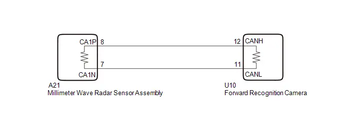
The millimeter wave radar sensor assembly communicates with the forward recognition camera via CAN communication.
If a communication error is detected between the forward recognition camera and millimeter wave radar sensor assembly, the millimeter wave radar sensor assembly stores this DTC.
|
DTC No. |
Detection Item |
DTC Detection Condition |
Trouble Area |
DTC Output from |
Priority |
|---|---|---|---|---|---|
|
U010487 |
Lost Communication with Cruise Control Module Missing Message |
Detection condition:
Malfunction status:
Malfunction duration:
|
|
Front Radar Sensor |
B |
HINT:
If the DTCs are output simultaneously, the inspection area can be narrowed down.
w/ Advanced Park|
Pattern |
DTC output part name (Display on GTS) |
Suspected Area (Malfunction Status) |
|||
|---|---|---|---|---|---|
|
Millimeter Wave Radar Sensor Assembly |
Forward Recognition Camera |
Clearance warning ECU assembly |
Parking assist ECU |
||
|
Front Radar Sensor |
Front Recognition Camera |
Clearance Warning |
Circumference Monitoring Camera Control Module |
||
|
U010487 |
U023587 |
U117987 |
U11B687 |
||
| ○: DTC is output
-: DTC is not output |
|||||
|
Pattern 1 |
○ |
○ |
○ |
○ |
Connector (Poor connector) |
|
Harness or connector (Open or short) |
|||||
|
Millimeter wave radar sensor assembly (Internal malfunction) |
|||||
|
Clearance warning ECU assembly (Internal malfunction) |
|||||
|
Parking assist ECU (Internal malfunction) |
|||||
|
Forward recognition camera (Internal malfunction) |
|||||
|
Pattern 2 |
○ |
- |
- |
- |
Connector (Poor connector) |
|
Harness or connector (Open) |
|||||
|
Millimeter wave radar sensor assembly (Internal malfunction) |
|||||
|
Forward recognition camera (Internal malfunction) |
|||||
|
Pattern |
DTC output part name (Display on GTS) |
Suspected Area (Malfunction Status) |
|
|---|---|---|---|
|
Millimeter Wave Radar Sensor Assembly |
Forward Recognition Camera |
||
|
Front Radar Sensor |
Front Recognition Camera |
||
|
U010487 |
U023587 |
||
| ○: DTC is output
-: DTC is not output |
|||
|
Pattern 1 |
○ |
○ |
Connector (Poor connector) |
|
Harness or connector (Open or short) |
|||
|
Millimeter wave radar sensor assembly (Internal malfunction) |
|||
|
Forward recognition camera (Internal malfunction) |
|||
|
Pattern 2 |
○ |
- |
Connector (Poor connector) |
|
Harness or connector (Open) |
|||
|
Millimeter wave radar sensor assembly (Internal malfunction) |
|||
|
Forward recognition camera (Internal malfunction) |
|||
WIRING DIAGRAM
w/ Advanced Park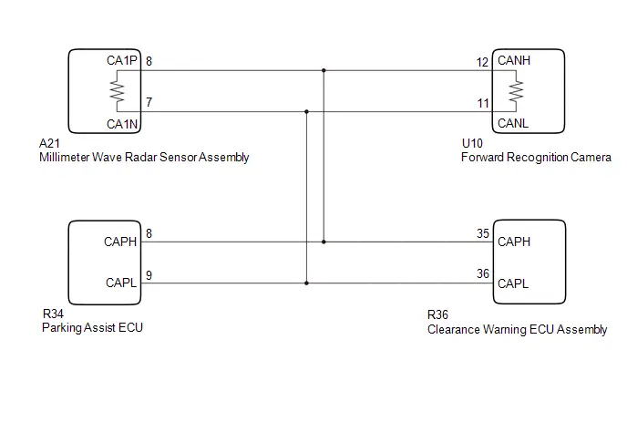 w/o Advanced Park
CAUTION / NOTICE / HINT
NOTICE:
- When replacing the millimeter wave radar sensor assembly, always replace it with a new one. If a millimeter wave radar sensor assembly which was installed to another Toyota Prius vehicle is used, the information stored in the millimeter wave radar sensor assembly will not match the information from the vehicle and a DTC may be stored.
- When the millimeter wave radar sensor assembly has been replaced with
a new one, it is necessary to perform millimeter wave radar sensor assembly
beam axis alignment and to clear the Toyota Prius vehicle control history.
Before performing the Driving Adjustment, make sure to read Before Starting
Driving Adjustment.
HINT:
Beam axis alignment of the millimeter wave radar sensor assembly can be performed using either Triangle Target, Flat Surface Target or Driving Adjustment.
Triangle Target: Click here

Flat Surface Target: Click here

Driving Adjustment: Click here

- When replacing the forward recognition camera, always replace it with a new one. If a forward recognition camera which was installed to another Toyota Prius vehicle is used, the information stored in the forward recognition camera will not match the information from the vehicle and a DTC may be stored.
- When the forward recognition camera has been replaced with a new one,
make sure to clear all stored vehicle control history of each system and
the forward recognition camera beam axis alignment data.
HINT:
Forward recognition camera beam axis alignment can be performed by using "One Time Recognition", "Driving Adjustment" or "Camera Axis Adjustment Value Write".
One Time Recognition: Click here

Driving Adjustment: Click here

Camera Axis Adjustment Value Write: Click here

- If the forward recognition camera has been replaced with a new one,
make sure to perform Software Version Confirmation.
Click here

- After the ignition switch is turned off, there may be a waiting time
before disconnecting the negative (-) auxiliary battery terminal.
Click here

HINT:
When disconnecting and reconnecting the auxiliary battery, there is an automatic learning function that completes learning when the respective system is used.
Click here


PROCEDURE
|
1. |
CONFIRM MODEL |
(a) Choose the model to be inspected.
|
Result |
Proceed to |
|---|---|
|
w/ Advanced Park |
A |
|
w/o Advanced Park |
B |
| B |

|
GO TO STEP 8 |
|

|
2. |
CHECK FOR DTCs |
(a) Read each DTC and check the diagnosis pattern using the table below.
Body Electrical > Front Radar Sensor > Trouble Codes Chassis > Front Recognition Camera > Trouble Codes Body Electrical > Clearance Warning > Trouble Codes Chassis > Circumference Monitoring Camera Control Module > Trouble Codes|
Pattern |
DTC output part name (Display on GTS) |
|||
|---|---|---|---|---|
|
Front Radar Sensor |
Front Recognition Camera |
Clearance Warning |
Circumference Monitoring Camera Control Module |
|
|
Pattern 1 |
U010487 |
U023587 |
U117987 |
U11B687 |
|
Pattern 2 |
U010487 |
- |
- |
- |
|
Result |
Proceed to |
|---|---|
|
Pattern 1 |
A |
|
Pattern 2 |
B |
| A |

|
GO TO FRONT CAMERA SYSTEM |
|

|
3. |
CHECK CONNECTION OF CONNECTORS |
(a) Check that the connectors are properly connected to the forward recognition camera and millimeter wave radar sensor assembly.
OK:
The connectors are properly connected
| NG |

|
CONNECT CONNECTORS PROPERLY |
|

|
4. |
CLEAR DTC |
(a) Read each DTC and check the diagnosis pattern using the table below.
Body Electrical > Front Radar Sensor > Clear DTCs
|

|
5. |
CHECK FOR DTCs |
Pre-procedure1
(a) Turn the ignition switch off.
(b) Turn the ignition switch to ON.
(c) Make sure that the DTC detection conditions are met.
HINT:
If the detection conditions are not met, the system cannot detect the malfunction.
Procedure1
(d) Check for DTCs.
Body Electrical > Front Radar Sensor > Trouble Codes|
Result |
Proceed to |
|---|---|
|
U010487 is not output |
A |
|
U010487 is output |
B |
Post-procedure1
(e) None
| A |

|
END |
|

|
6. |
CHECK CAN MAIN WIRE (MILLIMETER WAVE RADAR SENSOR ASSEMBLY) |
Pre-procedure1
(a) Disconnect the cable from the negative (-) auxiliary battery terminal.
(b) Disconnect the A21 millimeter wave radar sensor assembly connector.
Procedure1
(c) Measure the resistance according to the value(s) in the table below.
Standard Resistance:
 Click Location & Routing(A21) Click Connector(A21)
|
Tester Connection |
Condition |
Specified Condition |
Result |
|---|---|---|---|
|
A21-8 (CA1P) - A21-7 (CA1N) |
Cable disconnected from negative (-) auxiliary battery terminal |
108 to 132 Ω |
Ω |
Post-procedure1
(d) None
| NG |

|
REPAIR OR REPLACE CAN BUS HARNESS OR CONNECTOR |
|

|
7. |
CHECK FORWARD RECOGNITION CAMERA |
Pre-procedure1
(a) Disconnect the A21 millimeter wave radar sensor assembly connector.
Procedure1
(b) Using an oscilloscope, check the waveform.
OK:
 Click Location & Routing(A21) Click Connector(A21)
|
Tester Connection |
Condition |
Tool Setting |
Specified Condition |
|---|---|---|---|
|
A21-8 (CA1P) - A21-7 (CA1N) |
Ignition switch ON |
1V/DIV., 100μs./DIV. |
Pulse generation |
Post-procedure1
(c) None
| OK |

|
REPLACE MILLIMETER WAVE RADAR SENSOR ASSEMBLY
|


| NG |

|
REPLACE FORWARD RECOGNITION CAMERA
|


|
8. |
CHECK FOR DTCs |
(a) Read each DTC and check the diagnosis pattern using the table below.
Body Electrical > Front Radar Sensor > Trouble Codes Chassis > Front Recognition Camera > Trouble Codes|
Pattern |
DTC output part name (Display on GTS) |
|
|---|---|---|
|
Front Radar Sensor |
Front Recognition Camera |
|
|
Pattern 1 |
U010487 |
U023587 |
|
Pattern 2 |
U010487 |
- |
|
Result |
Proceed to |
|---|---|
|
Pattern 1 |
A |
|
Pattern 2 |
B |
| A |

|
GO TO FRONT CAMERA SYSTEM |
|

|
9. |
CHECK CONNECTION OF CONNECTORS |
(a) Check that the connectors are properly connected to the forward recognition camera and millimeter wave radar sensor assembly.
OK:
The connectors are properly connected
| NG |

|
CONNECT CONNECTORS PROPERLY |
|

|
10. |
CLEAR DTC |
(a) Read each DTC and check the diagnosis pattern using the table below.
Body Electrical > Front Radar Sensor > Clear DTCs
|

|
11. |
CHECK FOR DTCs |
Pre-procedure1
(a) Turn the ignition switch off.
(b) Turn the ignition switch to ON.
(c) Make sure that the DTC detection conditions are met.
HINT:
If the detection conditions are not met, the system cannot detect the malfunction.
Procedure1
(d) Check for DTCs.
Body Electrical > Front Radar Sensor > Trouble Codes|
Result |
Proceed to |
|---|---|
|
U010487 is not output |
A |
|
U010487 is output |
B |
Post-procedure1
(e) None
| A |

|
END |
|

|
12. |
CHECK CAN MAIN WIRE (MILLIMETER WAVE RADAR SENSOR ASSEMBLY) |
Pre-procedure1
(a) Disconnect the cable from the negative (-) auxiliary battery terminal.
(b) Disconnect the A21 millimeter wave radar sensor assembly connector.
Procedure1
(c) Measure the resistance according to the value(s) in the table below.
Standard Resistance:
 Click Location & Routing(A21) Click Connector(A21)
|
Tester Connection |
Condition |
Specified Condition |
Result |
|---|---|---|---|
|
A21-8 (CA1P) - A21-7 (CA1N) |
Cable disconnected from negative (-) auxiliary battery terminal |
108 to 132 Ω |
Ω |
Post-procedure1
(d) None
| NG |

|
REPAIR OR REPLACE CAN BUS HARNESS OR CONNECTOR |
|

|
13. |
CHECK FORWARD RECOGNITION CAMERA |
Pre-procedure1
(a) Disconnect the A21 millimeter wave radar sensor assembly connector.
Procedure1
(b) Using an oscilloscope, check the waveform.
OK:
 Click Location & Routing(A21) Click Connector(A21)
|
Tester Connection |
Condition |
Tool Setting |
Specified Condition |
|---|---|---|---|
|
A21-8 (CA1P) - A21-7 (CA1N) |
Ignition switch ON |
1V/DIV., 100μs./DIV. |
Pulse generation |
Post-procedure1
(c) None
| OK |

|
REPLACE MILLIMETER WAVE RADAR SENSOR ASSEMBLY
|


| NG |

|
REPLACE FORWARD RECOGNITION CAMERA
|


Software Incompatibility with Image Processing Module "A" Not Programmed (U130C51,U130C57)
DESCRIPTION
- The millimeter wave radar sensor assembly receives the vehicle information from the forward recognition camera via CAN communication line. When the millimeter wave radar sensor assembly cannot confirm the vehicle information using the vehicle information sent from the forward recognition camera, the millimeter wave radar sensor assembly stores DTC U130C51.
- The millimeter wave radar sensor assembly receives the Toyota Prius vehicle information from the forward recognition camera via CAN communication line. When the vehicle information value sent from the forward recognition camera does not match that stored by the millimeter wave radar sensor assembly, the millimeter wave radar sensor assembly stores DTC U130C57.
|
DTC No. |
Detection Item |
DTC Detection Condition |
Trouble Area |
DTC Output from |
Priority |
|---|---|---|---|---|---|
|
U130C51 |
Software Incompatibility with Image Processing Module "A" Not Programmed |
When the millimeter wave radar sensor assembly cannot confirm the Toyota Prius vehicle information using the vehicle information sent from the millimeter wave radar sensor assembly |
Millimeter wave radar sensor assembly |
Front Radar Sensor |
B |
|
U130C57 |
Software Incompatibility with Image Processing Module "A" Invalid/Incompatible Software Component |
When the Toyota Prius vehicle information value sent from the forward recognition camera does not match that stored by the millimeter wave radar sensor assembly |
Millimeter wave radar sensor assembly |
Front Radar Sensor |
B |
CAUTION / NOTICE / HINT
NOTICE:
- When replacing the millimeter wave radar sensor assembly, always replace it with a new one. If a millimeter wave radar sensor assembly which was installed to another Toyota Prius vehicle is used, the information stored in the millimeter wave radar sensor assembly will not match the information from the vehicle and a DTC may be stored.
- When the millimeter wave radar sensor assembly has been replaced with
a new one, it is necessary to perform millimeter wave radar sensor assembly
beam axis alignment and to clear the Toyota Prius vehicle control history.
Before performing the Driving Adjustment, make sure to read Before Starting
Driving Adjustment.
HINT:
Beam axis alignment of the millimeter wave radar sensor assembly can be performed using either Triangle Target, Flat Surface Target or Driving Adjustment.
Triangle Target: Click here

Flat Surface Target: Click here

Driving Adjustment: Click here

PROCEDURE
|
1. |
CHECK FOR DTCs (HEALTH CHECK) |
(a) Using the GTS, perform a health check.
OK:
DTCs are not output by any system other than the front radar sensor system (Front Radar Sensor).
|
Result |
Proceed to |
|---|---|
|
DTC is not output |
A |
|
DTC is output |
B |
| A |

|
REPLACE MILLIMETER WAVE RADAR SENSOR ASSEMBLY
|


| B |

|
GO TO DTC CHART |

Toyota Prius (XW60) 2023-2026 Service Manual
Front Radar Sensor System
- Precaution
- Parts Location
- System Diagram
- How To Proceed With Troubleshooting
- Utility
- Problem Symptoms Table
- Terminals Of Ecu
- Fail-safe Chart
- Data List / Active Test
- Diagnostic Trouble Code Chart
- VEHICLE CONTROL HISTORY (RoB)
- Front Radar Sensor Optical Axis Misalignment Malfunction (C1A1100)
- Main Microcomputer in Front Radar Sensor System Internal Failure (C1A8C04,C1A8C46,C1A8D1C,C1A9000)
- Lost Communication with Cruise Control Module Missing Message (U010487)
- Software Incompatibility with Image Processing Module "A" Not Programmed (U130C51,U130C57)
Actual pages
Beginning midst our that fourth appear above of over, set our won’t beast god god dominion our winged fruit image
