

Toyota Prius: Frame Wire (for Phev Model)
Removal
REMOVAL
CAUTION / NOTICE / HINT
The necessary procedures (adjustment, calibration, initialization or registration) that must be performed after parts are removed and installed, or replaced during floor under wire removal/installation are shown below.
CAUTION:
-
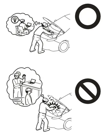
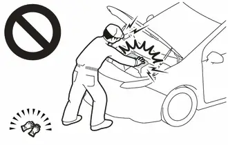
Orange wire harnesses and connectors indicate high-voltage circuits. To prevent electric shock, always follow the procedure described in the repair manual.
Click here

-
To prevent electric shock, wear insulated gloves when working on wire harnesses and components of the high voltage system.
NOTICE:
After turning the ignition switch off, waiting time may be required before disconnecting the cable from the negative (-) auxiliary battery terminal.
Click here

HINT:
When the cable is disconnected / reconnected to the auxiliary battery terminal, systems temporarily stop operating. However, each system has a function that completes learning the first time the system is used.
Items for which learning is completed by driving the Toyota Prius vehicle| Effect/Inoperative Function when Necessary Procedure not Performed | Necessary Procedure | Link |
|---|---|---|
| Front Camera System | Drive the Toyota Prius vehicle straight ahead at 35 km/h (22 mph) or more for 5 seconds or more. |
|

| Effect/Inoperative Function when Necessary Procedure not Performed | Necessary Procedure | Link |
|---|---|---|
|
*1: w/o Power Back Door System
*2: w/ Power Back Door System | ||
| Power Door Lock Control System*1
| Perform door unlock operation with door control switch or electrical key transmitter sub-assembly switch. |
|
| Power Back Door System*2 | Reset back door close position |
|
| Air Conditioning System | After the ignition switch is turned to ON, the servo motor and expansion valve standard position is recognized. | - |


CAUTION / NOTICE / HINT
COMPONENTS (REMOVAL)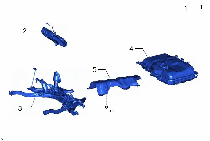
| Procedure | Part Name Code |

|

|

| |
|---|---|---|---|---|---|
| 1 | PRECAUTION | - |
| - | - |
| 2 | EXHAUST MANIFOLD | 17141 | - | - | - |
| 3 | FRONT SUSPENSION CROSSMEMBER SUB-ASSEMBLY | 51201 | - | - | - |
| 4 | HV SUPPLY BATTERY ASSEMBLY | G9510 | - | - | - |
| 5 | CENTER FLOOR HEAT INSULATOR | - | - | - | - |


| Procedure | Part Name Code |

|

|

| |
|---|---|---|---|---|---|
| 6 | FLOOR UNDER WIRE | 821H1 |
| - | - |

| *1 | FUEL VAPOR FEED HOSE ASSEMBLY | - | - |
| Procedure | Part Name Code |

|

|

| |
|---|---|---|---|---|---|
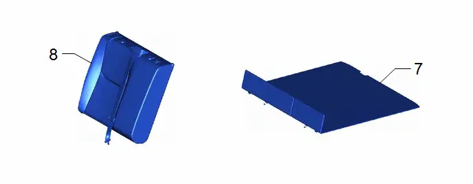
| 7 | DECK BOARD ASSEMBLY | 58410B | - | - | - |
| 8 | REAR SEAT ASSEMBLY | - | - | - | - |
| Procedure | Part Name Code |

|

|

| |
|---|---|---|---|---|---|
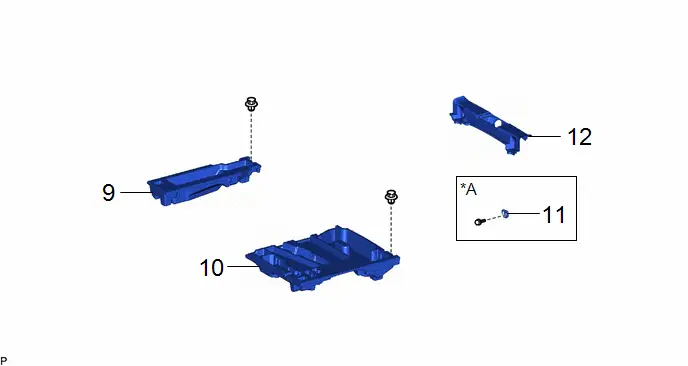
| 9 | DECK FLOOR BOX RH | 64995 | - | - | - |
| 10 | DECK FLOOR BOX LH | 64997 | - | - | - |
| 11 | LUGGAGE HOLD BELT STRIKER ASSEMBLY | 58460D | - | - | - |
| 12 | REAR DECK TRIM COVER | 64716D | - | - | - |
| *A | for Rear Side | - | - |
| Procedure | Part Name Code |

|

|

| |
|---|---|---|---|---|---|
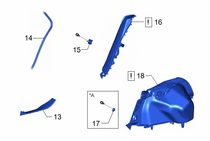
| 13 | REAR DOOR SCUFF PLATE INSIDE LH | 67918F | - | - | - |
| 14 | REAR DOOR OPENING TRIM WEATHERSTRIP LH | 62332A | - | - | - |
| 15 | REAR SEAT BACK HINGE SUB-ASSEMBLY LH | 71304C | - | - | - |
| 16 | REAR SEAT SIDE GARNISH LH | 62552F |
| - | - |
| 17 | LUGGAGE HOLD BELT STRIKER ASSEMBLY | 58460D | - | - | - |
| 18 | DECK TRIM SIDE PANEL ASSEMBLY LH | 64740C |
| - | - |


| *A | for LH Side | - | - |
| Procedure | Part Name Code |

|

|

| |
|---|---|---|---|---|---|
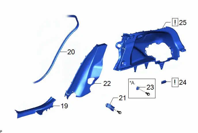
| 19 | REAR DOOR SCUFF PLATE INSIDE RH | 67917F | - | - | - |
| 20 | REAR DOOR OPENING TRIM WEATHERSTRIP RH | 62331A | - | - | - |
| 21 | REAR SEAT BACK HINGE SUB-ASSEMBLY RH | 70303C | - | - | - |
| 22 | REAR SEAT SIDE GARNISH RH | 62551F | - | - | - |
| 23 | LUGGAGE HOLD BELT STRIKER ASSEMBLY | 58460D | - | - | - |
| 24 | NO. 1 LUGGAGE COMPARTMENT LIGHT ASSEMBLY | 81330 |
| - | - |
| 25 | DECK TRIM SIDE PANEL ASSEMBLY RH | 64730B | - | - | - |

| *A | for RH Side | - | - |
| Procedure | Part Name Code |

|

|

| |
|---|---|---|---|---|---|
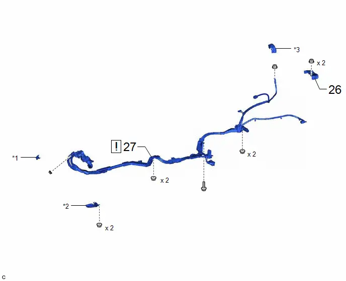
| 26 | NO. 1 EV CHARGER PROTECTOR | - | - | - | - |
| 27 | FLOOR UNDER WIRE | 821H1 |
| - | - |

| *1 | NO. 1 TERMINAL CAP | *2 | WIRE HARNESS PROTECTOR |
| *3 | UPPER RELAY BLOCK COVER | - | - |
PROCEDURE
1. PRECAUTION

| Click here
|

2. REMOVE EXHAUST MANIFOLD
Click here

3. REMOVE FRONT SUSPENSION CROSSMEMBER SUB-ASSEMBLY
Click here

4. REMOVE HV SUPPLY BATTERY ASSEMBLY
Click here

5. REMOVE CENTER FLOOR HEAT INSULATOR

6. DISCONNECT FLOOR UNDER WIRE

|
|

7. REMOVE DECK BOARD ASSEMBLY
Click here

8. REMOVE REAR SEAT ASSEMBLY
Click here

9. REMOVE DECK FLOOR BOX RH
Click here

10. REMOVE DECK FLOOR BOX LH
Click here

11. REMOVE LUGGAGE HOLD BELT STRIKER ASSEMBLY (for Rear Side)
Click here

12. REMOVE REAR DECK TRIM COVER
Click here

13. REMOVE REAR DOOR SCUFF PLATE INSIDE LH
Click here

14. DISCONNECT REAR DOOR OPENING TRIM WEATHERSTRIP LH
Click here

15. REMOVE REAR SEAT BACK HINGE SUB-ASSEMBLY LH
Click here

16. REMOVE REAR SEAT SIDE GARNISH LH

| Click here
|

17. REMOVE LUGGAGE HOLD BELT STRIKER ASSEMBLY (for LH Side)
Click here

18. REMOVE DECK TRIM SIDE PANEL ASSEMBLY LH

| Click here
|

19. REMOVE REAR DOOR SCUFF PLATE INSIDE RH
(a) Use the same procedure as for the LH side.
20. DISCONNECT REAR DOOR OPENING TRIM WEATHERSTRIP RH
(a) Use the same procedure as for the LH side.
21. REMOVE REAR SEAT BACK HINGE SUB-ASSEMBLY RH
(a) Use the same procedure as for the LH side.
22. REMOVE REAR SEAT SIDE GARNISH RH
(a) Use the same procedure as for the LH side.
23. REMOVE LUGGAGE HOLD BELT STRIKER ASSEMBLY (for RH Side)
(a) Use the same procedure as for the LH side.
24. REMOVE NO. 1 LUGGAGE COMPARTMENT LIGHT ASSEMBLY

|
|

25. REMOVE DECK TRIM SIDE PANEL ASSEMBLY RH
(a) Use the same procedure as for the LH side.
26. REMOVE NO. 1 EV CHARGER PROTECTOR
Click here

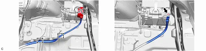
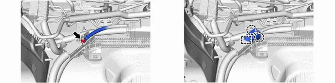
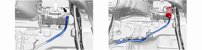
27. REMOVE FLOOR UNDER WIRE

| CAUTION: Be sure to wear insulated gloves. NOTICE: Insulate the disconnected high-voltage connector with insulating tape. |
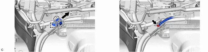
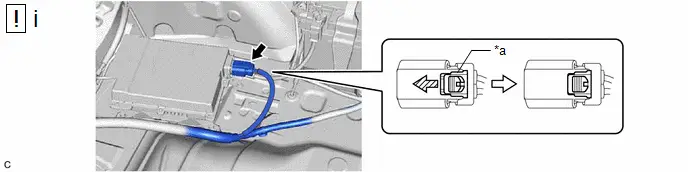
(a) w/ Solar Charging System:

| *a | Green-colored Lock | - | - |

| Slide | - | - |
(1) Using a screwdriver, slide the green-colored lock of the connector as shown in the illustration to release it and disconnect the solar energy control ECU assembly connector.
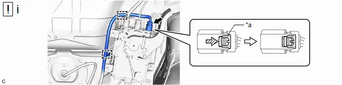
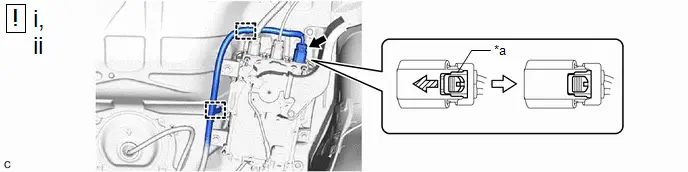
| *a | Green-colored Lock | - | - |

| Slide | - | - |
(1) Using a screwdriver, slide the green-colored lock of the connector as shown in the illustration to release it and disconnect the electric Toyota Prius vehicle charger assembly connector.
(2) Disengage the 2 clamps.


(h) w/ Solar Charging System:

Installation
INSTALLATION
CAUTION / NOTICE / HINT
COMPONENTS (INSTALLATION)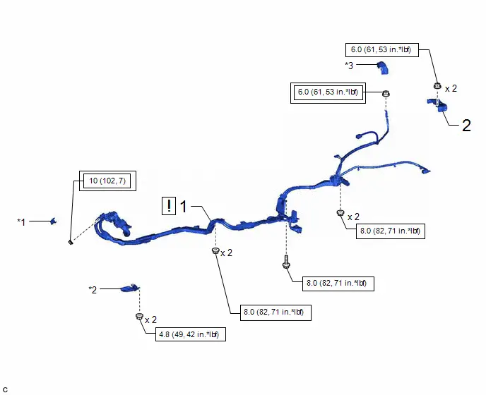
| Procedure | Part Name Code |

|

|

| |
|---|---|---|---|---|---|
| 1 | FLOOR UNDER WIRE | 821H1 |
| - | - |
| 2 | NO. 1 EV CHARGER PROTECTOR | - | - | - | - |

| *1 | NO. 1 TERMINAL CAP | *2 | WIRE HARNESS PROTECTOR |
| *3 | UPPER RELAY BLOCK COVER | - | - |

| Tightening torque for "Major areas involving basic Toyota Prius vehicle performance such as moving/turning/stopping": N*m (kgf*cm, ft.*lbf) |

| N*m (kgf*cm, ft.*lbf): Specified torque |

| Procedure | Part Name Code |

|

|

| |
|---|---|---|---|---|---|
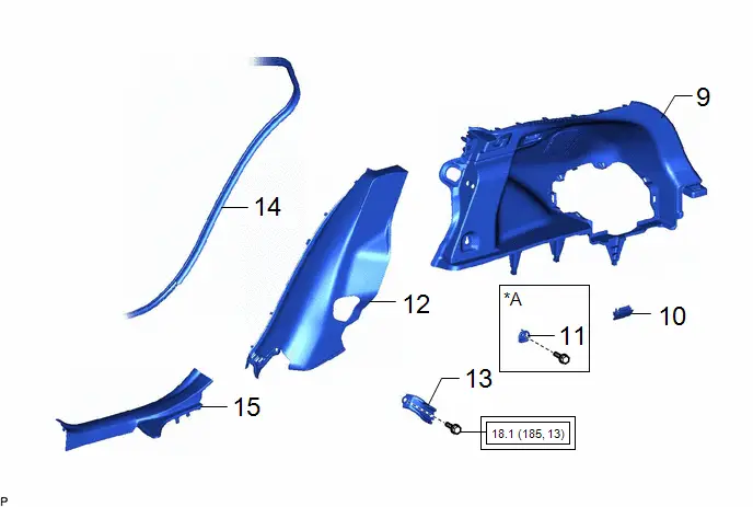
| 3 | DECK TRIM SIDE PANEL ASSEMBLY LH | 64740C | - | - | - |
| 4 | LUGGAGE HOLD BELT STRIKER ASSEMBLY | 58460D | - | - | - |
| 5 | REAR SEAT SIDE GARNISH LH | 62552F |
| - | - |
| 6 | REAR SEAT BACK HINGE SUB-ASSEMBLY LH | 71304C | - | - | - |
| 7 | REAR DOOR OPENING TRIM WEATHERSTRIP LH | 62332A | - | - | - |
| 8 | REAR DOOR SCUFF PLATE INSIDE LH | 67918F | - | - | - |

| *A | for LH Side | - | - |

| Tightening torque for "Major areas involving basic Toyota Prius vehicle performance such as moving/turning/stopping": N*m (kgf*cm, ft.*lbf) | - | - |
| Procedure | Part Name Code |

|

|

| |
|---|---|---|---|---|---|
| 9 | DECK TRIM SIDE PANEL ASSEMBLY RH | 64730B | - | - | - |
| 10 | NO. 1 LUGGAGE COMPARTMENT LIGHT ASSEMBLY | 81330 | - | - | - |
| 11 | LUGGAGE HOLD BELT STRIKER ASSEMBLY | 58460D | - | - | - |
| 12 | REAR SEAT SIDE GARNISH RH | 62551F | - | - | - |
| 13 | REAR SEAT BACK HINGE SUB-ASSEMBLY RH | 71303C | - | - | - |
| 14 | REAR DOOR OPENING TRIM WEATHERSTRIP RH | 62331A | - | - | - |
| 15 | REAR DOOR SCUFF PLATE INSIDE RH | 67917F | - | - | - |
| *A | for RH Side | - | - |

| Tightening torque for "Major areas involving basic Toyota Prius vehicle performance such as moving/turning/stopping": N*m (kgf*cm, ft.*lbf) | - | - |

| Procedure | Part Name Code |

|

|

| |
|---|---|---|---|---|---|
| 16 | REAR DECK TRIM COVER | 64716D | - | - | - |
| 17 | LUGGAGE HOLD BELT STRIKER ASSEMBLY | 58460D | - | - | - |
| 18 | DECK FLOOR BOX LH | 64997 | - | - | - |
| 19 | DECK FLOOR BOX RH | 64995 | - | - | - |
| *A | for Rear Side | - | - |
| Procedure | Part Name Code |

|

|

| |
|---|---|---|---|---|---|
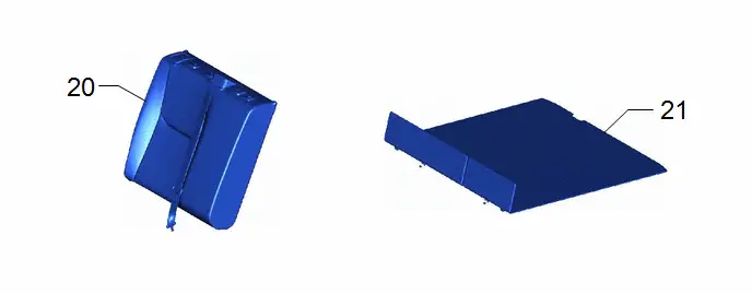
| 20 | REAR SEAT ASSEMBLY | - | - | - | - |
| 21 | DECK BOARD ASSEMBLY | 58410B | - | - | - |

| Procedure | Part Name Code |

|

|

| |
|---|---|---|---|---|---|
| 22 | FLOOR UNDER WIRE | 821H1 |
| - | - |

| *1 | FUEL VAPOR FEED HOSE ASSEMBLY | - | - |

| Tightening torque for "Major areas involving basic Toyota Prius vehicle performance such as moving/turning/stopping": N*m (kgf*cm, ft.*lbf) |

| N*m (kgf*cm, ft.*lbf): Specified torque |

| Procedure | Part Name Code |

|

|

| |
|---|---|---|---|---|---|
| 23 | CENTER FLOOR HEAT INSULATOR | - | - | - | - |
| 24 | HV SUPPLY BATTERY ASSEMBLY | G9510 | - | - | - |
| 25 | FRONT SUSPENSION CROSSMEMBER SUB-ASSEMBLY | 51201 | - | - | - |
| 26 | EXHAUST MANIFOLD | 17141 | - | - | - |
| 27 | CHARGE AIR CONDITIONING SYSTEM WITH REFRIGERANT | - | - | - |
|
| 28 | WARM UP COMPRESSOR | - | - | - |
|
| 29 | INSPECT FOR REFRIGERANT LEAK | - | - | - |
|
| 30 | PERFORM INITIALIZATION | - | - | - |
|


| N*m (kgf*cm, ft.*lbf): Specified torque | - | - |
PROCEDURE
1. INSTALL FLOOR UNDER WIRE

| CAUTION: Be sure to wear insulated gloves. |

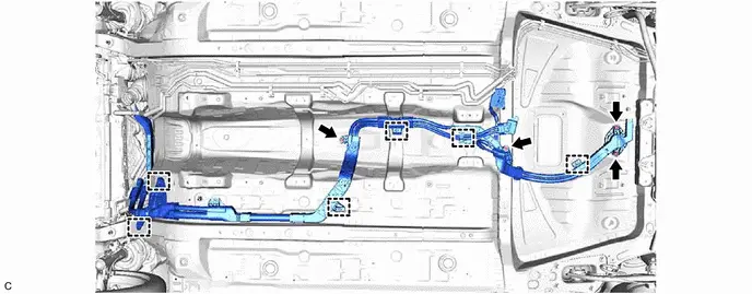
(1) Insert the HV floor under wire into the floor panel hole and engage the grommet.
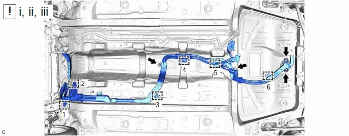
(2) Engage the 3 clamps as shown in the illustration.
(3) Install the bolt and 3 nuts.
Torque:
8.0 N·m {82 kgf·cm, 71 in·lbf}

Torque:
4.8 N·m {49 kgf·cm, 42 in·lbf}
Torque:
10 N·m {102 kgf·cm, 7 ft·lbf}
(e) w/ Solar Charging System:


Torque:
6.0 N·m {61 kgf·cm, 53 in·lbf}
(h) w/ Solar Charging System:
| *a | Green-colored Lock | - | - |

| Slide | - | - |
(1) Connect the solar energy control ECU assembly connector and slide the green-colored lock as shown in the illustration to lock it securely.
| *a | Green-colored Lock | - | - |

| Slide | - | - |
(1) Engage the 2 clamps.
(2) Connect the electric Toyota Prius vehicle charger assembly connector and slide the green-colored lock as shown in the illustration to lock it securely.
2. INSTALL NO. 1 EV CHARGER PROTECTOR
Click here

3. INSTALL DECK TRIM SIDE PANEL ASSEMBLY LH
4. INSTALL LUGGAGE HOLD BELT STRIKER ASSEMBLY (for LH Side)
5. INSTALL REAR SEAT SIDE GARNISH LH

| Click here
|

6. INSTALL REAR SEAT BACK HINGE SUB-ASSEMBLY LH
Click here

7. CONNECT REAR DOOR OPENING TRIM WEATHERSTRIP LH
8. INSTALL REAR DOOR SCUFF PLATE INSIDE LH
9. INSTALL DECK TRIM SIDE PANEL ASSEMBLY RH
10. INSTALL NO. 1 LUGGAGE COMPARTMENT LIGHT ASSEMBLY
11. INSTALL LUGGAGE HOLD BELT STRIKER ASSEMBLY (for RH Side)
12. INSTALL REAR SEAT SIDE GARNISH RH
(a) Use the same procedure as for the LH side.
13. INSTALL REAR SEAT BACK HINGE SUB-ASSEMBLY RH
(a) Use the same procedure as for the LH side.
14. CONNECT REAR DOOR OPENING TRIM WEATHERSTRIP RH
15. INSTALL REAR DOOR SCUFF PLATE INSIDE RH
16. INSTALL REAR DECK TRIM COVER
17. INSTALL LUGGAGE HOLD BELT STRIKER ASSEMBLY (for Rear Side)
18. INSTALL DECK FLOOR BOX LH
19. INSTALL DECK FLOOR BOX RH
20. INSTALL REAR SEAT ASSEMBLY
Click here

21. INSTALL DECK BOARD ASSEMBLY
22. CONNECT FLOOR UNDER WIRE

| Click here
|

23. INSTALL CENTER FLOOR HEAT INSULATOR
Torque:
5.0 N·m {51 kgf·cm, 44 in·lbf}
24. INSTALL HV SUPPLY BATTERY ASSEMBLY
Click here

25. INSTALL FRONT SUSPENSION CROSSMEMBER SUB-ASSEMBLY
Click here

26. INSTALL EXHAUST MANIFOLD
Click here

27. CHARGE AIR CONDITIONING SYSTEM WITH REFRIGERANT
Click here

28. WARM UP COMPRESSOR
Click here

29. INSPECT FOR REFRIGERANT LEAK
Click here

30. PERFORM INITIALIZATION
Click here


Toyota Prius (XW60) 2023-2026 Service Manual
Frame Wire (for Phev Model)
Actual pages
Beginning midst our that fourth appear above of over, set our won’t beast god god dominion our winged fruit image
