

Toyota Prius: Heater Relay (for Phev Model)
Removal
REMOVAL
CAUTION / NOTICE / HINT
The necessary procedures (adjustment, calibration, initialization or registration) that must be performed after parts are removed and installed, or replaced during No. 1 traction battery heater relay removal/installation are shown below.
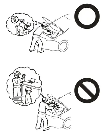
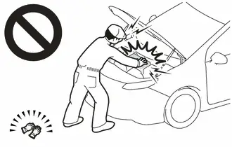
CAUTION:
-
Orange wire harnesses and connectors indicate high-voltage circuits. To prevent electric shock, always follow the procedure described in the repair manual.
Click here

-
To prevent electric shock, wear insulated gloves when working on wire harnesses and components of the high voltage system.
NOTICE:
After turning the ignition switch off, waiting time may be required before disconnecting the cable from the negative (-) auxiliary battery terminal.
Click here

HINT:
When the cable is disconnected / reconnected to the auxiliary battery terminal, systems temporarily stop operating. However, each system has a function that completes learning the first time the system is used.
Items for which learning is completed by driving the Toyota Prius vehicle| Effect/Inoperative Function when Necessary Procedure not Performed | Necessary Procedure | Link |
|---|---|---|
| Front Camera System | Drive the Toyota Prius vehicle straight ahead at 35 km/h (22 mph) or more for 5 seconds or more. |
|

| Effect/Inoperative Function when Necessary Procedure not Performed | Necessary Procedure | Link |
|---|---|---|
|
*1: w/o Power Back Door System
*2: w/ Power Back Door System | ||
| Power Door Lock Control System*1
| Perform door unlock operation with door control switch or electrical key transmitter sub-assembly switch. |
|
| Power Back Door System*2 | Reset back door close position |
|
| Air Conditioning System | After the ignition switch is turned to ON, the servo motor and expansion valve standard position is recognized. | - |


CAUTION / NOTICE / HINT
COMPONENTS (REMOVAL)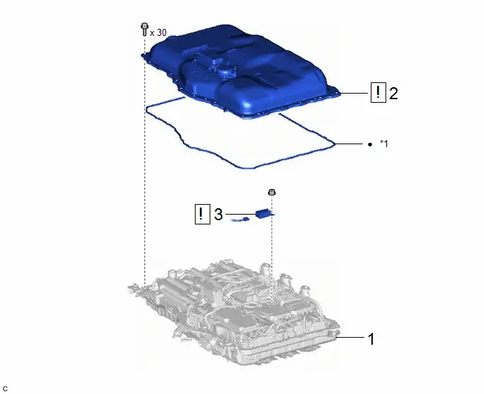
| Procedure | Part Name Code |

|

|

| |
|---|---|---|---|---|---|
| 1 | HV SUPPLY BATTERY ASSEMBLY | G9510 | - | - | - |
| 2 | NO. 1 TRACTION BATTERY COVER | - |
| - | - |
| 3 | NO. 1 TRACTION BATTERY HEATER RELAY | G96J1 |
| - | - |


| *1 | NO. 1 HV BATTERY SEAL | - | - |
| ● | Non-reusable part | - | - |
PROCEDURE
1. REMOVE HV SUPPLY BATTERY ASSEMBLY
Click here

2. REMOVE NO. 1 TRACTION BATTERY COVER

| Click here
|

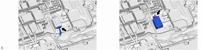
3. REMOVE NO. 1 TRACTION BATTERY HEATER RELAY

| CAUTION: Be sure to wear insulated gloves and protective goggles. |
Inspection
INSPECTION
PROCEDURE
1. INSPECT NO. 1 TRACTION BATTERY HEATER RELAY
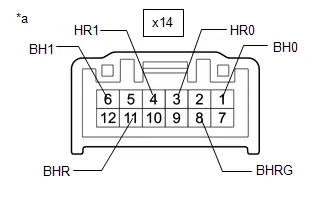
| (a) Measure the resistance according to the value(s) in the table below. Standard Resistance:  Click Location & Routing(x14) Click Connector(x14) Click Location & Routing(x14) Click Connector(x14)
If the result is not as specified, replace the No. 1 traction battery heater relay. |
|
Installation
INSTALLATION
CAUTION / NOTICE / HINT
COMPONENTS (INSTALLATION)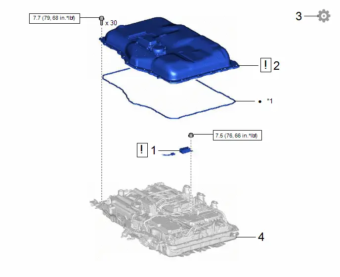
| Procedure | Part Name Code |

|

|

| |
|---|---|---|---|---|---|
| 1 | NO. 1 TRACTION BATTERY HEATER RELAY | G96J1 |
| - | - |
| 2 | NO. 1 TRACTION BATTERY COVER | - |
| - | - |
| 3 | CHECK FOR AIRTIGHTNESS | - | - | - |
|
| 4 | HV SUPPLY BATTERY ASSEMBLY | G9510 | - | - | - |


| *1 | NO. 1 HV BATTERY SEAL | - | - |

| N*m (kgf*cm, ft.*lbf): Specified torque | ● | Non-reusable part |
PROCEDURE
1. INSTALL NO. 1 TRACTION BATTERY HEATER RELAY

| CAUTION: Be sure to wear insulated gloves and protective goggles. |
Torque:
7.5 N·m {76 kgf·cm, 66 in·lbf}
2. INSTALL NO. 1 TRACTION BATTERY COVER

| Click here
|

3. CHECK FOR AIRTIGHTNESS (COMPONENT)
Click here

4. INSTALL HV SUPPLY BATTERY ASSEMBLY
Click here


Toyota Prius (XW60) 2023-2026 Service Manual
Heater Relay (for Phev Model)
Actual pages
Beginning midst our that fourth appear above of over, set our won’t beast god god dominion our winged fruit image
