

Toyota Prius: Electronically Controlled Brake System
- Precaution
- Definition Of Terms
- Parts Location
- System Diagram
- How To Proceed With Troubleshooting
- Problem Symptoms Table
- Terminals Of Ecu
- Diagnosis System
- Dtc Check / Clear
- Freeze Frame Data
- Signal Check
- Fail-safe Chart
- Data List / Active Test
- On-vehicle Inspection
- Inspection
- VEHICLE CONTROL HISTORY (RoB)
- Yaw Rate Sensor Circuit Intermittent (C00631F,C05201F)
- Yaw Rate Sensor Signal Bias Level Out of Range / Zero Adjustment Failure (C006328,C006396)
- Yaw Rate Sensor Signal Stuck In Range (C00632A,C05201C,C05202A,C052096)
- Left Front Wheel Speed Sensor Circuit Short to Battery (C050012)
- Left Front Wheel Speed Sensor Circuit Short to Ground or Open (C050014)
- Left Front Wheel Speed Sensor Circuit Intermittent (C05001F)
- Left Front Wheel Speed Sensor Signal Stuck Low (C050023)
- Left Front Wheel Speed Sensor Signal Has Too Many Pulses (C05003A,C05063A)
- Left Front Wheel Speed Sensor Signal Compare Failure (C050062)
- Right Front Wheel Speed Sensor Circuit Short to Battery (C050612)
- Right Front Wheel Speed Sensor Circuit Short to Ground or Open (C050614)
- Right Front Wheel Speed Sensor Circuit Intermittent (C05061F)
- Right Front Wheel Speed Sensor Signal Stuck Low (C050623)
- Right Front Wheel Speed Sensor Signal Compare Failure (C050662)
- Left Rear Wheel Speed Sensor Circuit Short to Battery (C050C12)
- Left Rear Wheel Speed Sensor Circuit Short to Ground or Open (C050C14)
- Left Rear Wheel Speed Sensor Signal Stuck Low (C050C23)
- Left Rear Wheel Speed Sensor Signal Has Too Many Pulses (C050C3A,C05123A)
- Left Rear Wheel Speed Sensor Signal Compare Failure (C050C62)
- Right Rear Wheel Speed Sensor Circuit Short to Battery (C051212)
- Right Rear Wheel Speed Sensor Circuit Short to Ground or Open (C051214)
- Right Rear Wheel Speed Sensor Circuit Intermittent (C05121F)
- Right Rear Wheel Speed Sensor Signal Stuck Low (C051223)
- Right Rear Wheel Speed Sensor Signal Compare Failure (C051262)
- Multi-axis Acceleration Sensor Module "A" (C051D00)
- Steering Angle Sensor Module Signal Stuck In Range (C05262A)
- Steering Angle Sensor Module Component Internal Failure (C052696)
- ABS Pump Motor Control Circuit Short to Ground or Open (C052C14,C052C16,C052C17,C052C49,C052F14)
- Brake Pressure Sensor "A" Circuit Voltage Below Threshold (C054016,...,C122D17)
- Brake Pressure Sensor "A" Circuit Voltage Above Threshold (C054017)
- Left Front Wheel Speed Sensor Incorrect Component Installed (C055595)
- Brake System Control Module "A" Internal Electronic Failure (C059749,C12F662,C12F762,C13BF62)
- Brake Pressure Sensor "E" Malfunction (C05A100,...,C14C017)
- Brake Pressure Sensor "E" Signal Bias Level Out of Range / Zero Adjustment Failure (C05A128)
- Brake Pedal Position Sensor "A" (C05C000)
- Brake Pressure Sensor "H" Signal Bias Level Out of Range / Zero Adjustment Failure (C063928)
- Ignition Switch On/Start Position Malfunction (C102000)
- Brake Pedal Position Sensor "A" Supply Voltage Malfunction (C110000)
- Brake Pedal Position Sensor "A" Supply Voltage Malfunction (C110000)
- Brake Pedal Position Sensor "A" Supply Voltage Circuit Voltage Out of Range (C11001C)
- Brake Pedal Position Sensor "B" Supply Voltage Circuit Voltage Out of Range (C11031C)
- Brake Pressure Sensor "H" / Brake Pedal Position Sensor Signal Compare Failure (C116C62)
- Brake Servo Pressure Sensor Pressure Increase Malfunction (C116D00)
- Electronic Brake Booster Motor Supply Voltage Circuit Short to Ground or Open (C117514)
- Master Reservoir Level Malfunction (C120200)
- Yaw Rate Sensor / Multi-axis Acceleration Sensor Module "A" (C124000)
- Braking System information System Programming Failure (C124A05)
- Electronic Brake Booster Control Module "A" Backup Power Supply Voltage Circuit Open (C125D13,C14C949,C14DD49)
- Electronic Brake Booster Control Module "A" Backup Power Supply Voltage System Voltage Low (C125DA2,C125DA3)
- Reservoir Level Switch Circuit Short to Battery or Open (C126E15)
- Electronic Brake Booster Motor "A" Position Sensor Signal Cross Coupled (C129A2B)
- Left Front Wheel ABS Hold Solenoid Control Circuit Short to Battery (C12A512,...,C12B014)
- Electronic Brake Booster Motor "A" Circuit Current Above Threshold (C12B419)
- Electronic Brake Booster Motor "A" Actuator Stuck (C12B471)
- Electronic Brake Booster Motor "A" Drive Circuit Missing Message (C12BF87)
- Left Rear Wheel ABS Hold Solenoid Control Circuit Short to Battery (C12D112,...,C12DC14)
- ECB Solenoid Control "A" Circuit Short to Battery (C12F812,C12F814)
- Linear Solenoid Valve Offset Learning (C134500)
- Linear Solenoid Valve Offset Learning Missing Calibration (C134554)
- Brake System Control Module "A" System Voltage System Voltage Low (C137BA2)
- Brake System Control Module "A" System Voltage System Voltage High (C137BA3)
- Stop Lamp Relay Actuator Stuck On (C13807E)
- Stop Lamp Relay Actuator Stuck Off (C13807F)
- Electronic Brake Booster Motor "A" Current Sensor Signal Cross Coupled (C13BA2B)
- Brake Pressure Too Low (Brake Booster) (C13D900)
- Brake Pressure Leak Malfunction (C140000,C140A00)
- ABS Pump Motor Actuator Stuck (C142771)
- ABS Solenoid Control Actuator Stuck On (C143A7E,C143A7F)
- Electronic Brake Booster Control Module "A" Supply Voltage Circuit Voltage Below Threshold (C14C616)
- Electronic Brake Booster Control Module "A" Supply Voltage Circuit Voltage Above Threshold (C14C617)
- Electronic Brake Booster Control Module "A" System Voltage Low (C14C9A2)
- Brake Fluid Air Bleeding Not Programmed (C14CE51)
- Brake Pressure Control solenoid Supply Voltage Circuit Short to Ground or Open (C14DD14)
- Left Front Wheel Speed Sensor Supply Voltage Circuit Short to Ground or Open (C14E014,C14E314)
- Steering Angle Sensor Supply Voltage Circuit Short to Ground or Open (C14FE14)
- Brake Switch "A" (P057100)
- Brake Pedal Position Sensor "A" (P057A00,P05E062)
- Brake Pedal Position Sensor "A" Circuit Short to Battery (P057A12,P057A14,P057A1F)
- Lost Communication with Drive Motor Control Module "A" (U011000,U012987,U029300,U110600,U114A00,U115000,U117D87)
- Brake Hold Standby Indicator Light Circuit
- Brake Hold Operated Indicator Light Circuit
- Steering Angle Sensor Wrong Installation (X0455)
- Zero Point Calibration of Yaw Rate Sensor Undone (X204C)
- Zero Point Calibration of Steering Angle Sensor Malfunction (X20D7)
- Zero Point Calibration of Steering Angle Sensor Not Acquired (X20D8)
- Excessive Brake Pedal Travel (No Fluid Leaks and No Air in System)
- ABS does not Operate
- ABS Operates Before Necessary When Braking
- Abnormal Brake Pedal Response on First Depression
- VSC OFF Switch Circuit
Precaution
PRECAUTION
PRECAUTION FOR DISCONNECTING CABLE FROM NEGATIVE AUXILIARY BATTERY TERMINAL
NOTICE:
After the ignition switch is turned off, there may be a waiting time before disconnecting the negative (-) auxiliary battery terminal.
Click here

HINT:
When disconnecting and reconnecting the auxiliary battery, there is an automatic learning function that completes learning when the respective system is used.
Click here


TROUBLESHOOTING PRECAUTIONS
(a) When there is a malfunction with terminal contact points or part installation problems, removal and installation of the suspected problem parts may return the system to the normal condition either completely or temporarily.
(b) Before disconnecting a connector or removing and installing a component in order to narrow down the malfunctioning part, make sure to perform the following procedure.
- Check for and record any DTCs and Freeze Frame Data that were stored around the time that the malfunction occurred.
-
If any open circuit DTCs related to intermittent (momentary interruptions) malfunctions are output, check the intermittent monitor.
Click here

NOTICE:
When disconnecting a connector or removing a fuse or relay, make sure that the ignition switch is off, the brake pedal is not depressed, and the driver door has been closed for 4 minutes or more*.
*: Differs according to Toyota Prius vehicle conditions
(c) Since the system may be influenced by malfunctions in systems other than the brake control system, be sure to check for DTCs in other systems.
HANDLING PRECAUTIONS
(a) Do not remove or install electronically controlled brake system parts such as the steering angle sensor, yaw rate and acceleration sensor (airbag ECU assembly) or brake pedal stroke sensor assembly except when required, as they need to be adjusted correctly after removal and installation.
(b) Be sure to perform preparation before work and confirmation after work is completed by following the directions in the repair manual when working on the electronically controlled brake system.
(c) When removing/installing or replacing an electronically controlled brake system related component, disconnect the cable from the negative (-) auxiliary battery terminal before performing the procedure.
NOTICE:
After turning the ignition switch off, waiting time may be required before disconnecting the cable from the negative (-) auxiliary battery terminal. Therefore, make sure to read the disconnecting the cable from the negative (-) auxiliary battery terminal notice before proceeding with work.
Click here

(d) This system is equipped with 2 skid control ECUs; the No. 1 skid control ECU (brake booster with master cylinder assembly) and No. 2 skid control ECU (brake actuator assembly). For this reason, it is necessary to follow the specified procedure when reading DTCs, Freeze Frame Data, the Data List, etc.
The respective menus for each ECU are as follows:- No. 1 skid control ECU: Chassis / Brake Booster
-
No. 2 skid control ECU: Chassis / Brake/EPB*
*: Electric Parking Brake System
(e) If the No. 1 skid control ECU (brake booster with master cylinder assembly), No. 2 skid control ECU (brake actuator assembly) or a sensor has been removed and installed, it is necessary to check the system for problems after the parts have been reassembled. Check for DTCs using the GTS. Also check that the system functions and signals received by the ECU are normal using Dealer Mode (Signal Check).
HINT:
If a Dealer Mode (Signal Check) inspection is not performed, a sensor not calibrated malfunction DTC may be stored even if the No. 1 skid control ECU (brake booster with master cylinder assembly), No. 2 skid control ECU (brake actuator assembly) and all sensors are normal.
(f) If the brake pedal is depressed before the brake control system is prepared to operate, the pedal stroke may seem unusually long or short. This is due to the fact the stroke simulator cut solenoid has not yet operated and is not a malfunction.
After the ignition switch is turned to ON or the brake pedal is depressed twice or more, the stroke simulator will operate and the brake pedal stroke will remain consistent.
DTC PRECAUTION
(a) Warnings for some DTCs cannot be cleared by only repairing the malfunctioning parts. If the warning is displayed even after repair work, the DTC should be cleared after turning the ignition switch off.
NOTICE:
If a DTC for a malfunctioning part reappears after it is cleared, then it has been stored again.
PRECAUTIONS FOR REMOVAL, INSTALLATION AND REPLACEMENT OF COMPONENTS
(a) After replacing certain components, it may be necessary to update the ECU security key.
Click here


(b) Perform "Calibration" after removal, installation or replacement of any of the following components:
Click here

- No. 1 skid control ECU (brake booster with master cylinder assembly)
- No. 2 skid control ECU (brake actuator assembly)
- Brake pedal stroke sensor assembly (including when performing an adjustment)
- Brake pedal
- Yaw rate and acceleration sensor (airbag ECU assembly)
(c) Perform Dealer Mode (Signal Check) inspection after removal, installation or replacement of any of the following components:
Click here

- Speed sensor
- Speed sensor rotor
CHASSIS DYNAMOMETER PRECAUTION
(a) Enter Inspection Mode to disable TRAC and VSC operation when using a chassis dynamometer.
Refer to Inspection Mode Procedure: Click here

CAUTION:
-
Do not use the drum tester with any of the lock chains disconnected.
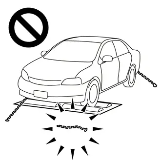
- Using the drum tester with a lock chain disconnected could cause the Toyota Prius vehicle to begin moving unexpectedly.
-
Do not use the drum tester while the TRAC or VSC is able to operate.
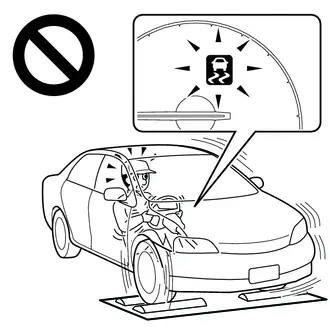
- TRAC or VSC operation could cause the vehicle to begin moving unexpectedly.
CAN COMMUNICATION SYSTEM PRECAUTIONS
(a) The CAN communication system is used for communication between the No. 1 skid control ECU (brake booster with master cylinder assembly), No. 2 skid control ECU (brake actuator assembly), steering angle sensor, yaw rate and acceleration sensor (airbag ECU assembly) and other ECUs. If there is a malfunction in a CAN communication line, corresponding DTCs for the communication line are output.
(b) If any CAN communication DTCs are output, repair the malfunction, then troubleshoot the electronically controlled brake system while communication is normal.
(c) In order to enable CAN communication, a specific type of wiring is used for the CAN communication lines. The wiring used for each communication line is a twisted pair of wires that have an equal length. A bypass wire should not be used, because the data being transmitted will be corrupted.
Definition Of Terms
DEFINITION OF TERMS
| Term | Definition |
|---|---|
| Monitor Description | Description of what the skid control ECU monitors and how it detects malfunctions (monitoring purpose and details). |
| Related DTCs | Group of diagnostic trouble codes that are output by the skid control ECU based on the same malfunction detection logic. |
| Typical Enabling Conditions | Preconditions that allow the skid control ECU to detect malfunctions. With all preconditions satisfied, the skid control ECU stores a DTC when the monitored value(s) exceeds the malfunction threshold(s). |
| Sequence of Operation | The priority order that is applied to monitoring if multiple sensors and components are used to detect the malfunction. While one sensor is being monitored, the next sensor or component will not be monitored. |
| Required Sensors/Components | The sensors and components that are used by the skid control ECU to detect malfunctions. |
| Frequency of Operation | The number of times that the skid control ECU checks for malfunctions per driving cycle. "Continuous" means that the skid control ECU checks for malfunctions every time the enabling conditions are met. "During initial checking" means that the skid control ECU checks for malfunctions for approximately 3 seconds after the ignition switch is turned to ON (while the initial check being performed). "After ignition switch off" means that after the ignition switch is turned off, the system check which is performed using residual power checks for malfunctions that are difficult to detect during normal operation, within a certain amount of time. |
| Duration | The minimum time for which the skid control ECU must detect a continuous deviation in the monitored value(s) in order to store a DTC. Timing begins after the "typical enabling conditions" are met. |
| Typical Malfunction Thresholds | Value beyond which the skid control ECU will determine that there is a malfunction and stores a DTC. |
| MIL Operation | MIL illumination timing after a malfunction is detected. "Immediate" means that the skid control ECU illuminates the MIL the instant the skid control ECU determines that there is a malfunction. |
| Component Operating Range | Normal operation range of sensors and solenoids under normal driving conditions. Use these ranges as a reference. They cannot be used to judge if a sensor or solenoid is defective or not. |
Parts Location
PARTS LOCATION
ILLUSTRATION
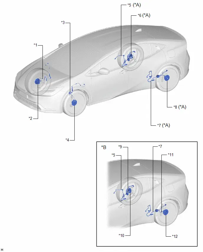
| *A | for 2WD | *B | for AWD |
| *1 | FRONT SPEED SENSOR RH | *2 | FRONT AXLE HUB SUB-ASSEMBLY RH - FRONT SPEED SENSOR ROTOR RH |
| *3 | FRONT SPEED SENSOR LH | *4 | FRONT AXLE HUB SUB-ASSEMBLY LH - FRONT SPEED SENSOR ROTOR LH |
| *5 | NO. 1 PARKING BRAKE WIRE ASSEMBLY - SKID CONTROL SENSOR WIRE RH | *6 | REAR AXLE HUB AND BEARING ASSEMBLY RH - REAR SPEED SENSOR ROTOR RH - REAR SPEED SENSOR RH |
| *7 | NO. 2 PARKING BRAKE WIRE ASSEMBLY - SKID CONTROL SENSOR WIRE LH | *8 | REAR AXLE HUB AND BEARING ASSEMBLY LH - REAR SPEED SENSOR ROTOR LH - REAR SPEED SENSOR LH |
| *9 | REAR SPEED SENSOR RH (REAR SKID CONTROL SENSOR RH) | *10 | REAR AXLE HUB AND BEARING ASSEMBLY RH - REAR SPEED SENSOR ROTOR RH |
| *11 | REAR SPEED SENSOR LH (REAR SKID CONTROL SENSOR LH) | *12 | REAR AXLE HUB AND BEARING ASSEMBLY LH - REAR SPEED SENSOR ROTOR LH |
ILLUSTRATION

| *1 | BRAKE ACTUATOR ASSEMBLY - NO. 2 SKID CONTROL ECU | *2 | FRONT DOOR LOCK WITH MOTOR ASSEMBLY (for Driver Side) |
| *3 | INVERTER WITH CONVERTER ASSEMBLY | *4 | BRAKE BOOSTER WITH MASTER CYLINDER ASSEMBLY - NO. 1 SKID CONTROL ECU - BRAKE ACTUATOR - BRAKE FLUID LEVEL WARNING SWITCH |
| *5 | NO. 1 ENGINE ROOM RELAY BLOCK AND NO. 1 JUNCTION BLOCK ASSEMBLY - ABS MAIN FUSE - ABS MTR NO. 1 FUSE - ABS NO. 1 FUSE - ABS NO. 2 FUSE - ECU-IGP NO. 3 FUSE - 2ND BATT FUSE | *6 | ECM |
ILLUSTRATION
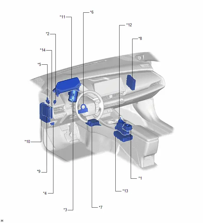
| *1 | ELECTRIC PARKING BRAKE SWITCH ASSEMBLY - VSC OFF SWITCH - BRAKE HOLD SWITCH | *2 | STOP LIGHT SWITCH ASSEMBLY - STOP LIGHT CONTROL RELAY |
| *3 | POWER STEERING ECU ASSEMBLY | *4 | DLC3 |
| *5 | BRAKE PEDAL STROKE SENSOR ASSEMBLY | *6 | STEERING ANGLE SENSOR |
| *7 | AIRBAG ECU ASSEMBLY - YAW RATE SENSOR - ACCELERATION SENSOR | *8 | HYBRID Toyota Prius Vehicle CONTROL ECU |
| *9 | MAIN BODY ECU (MULTIPLEX NETWORK BODY ECU) | *10 | POWER DISTRIBUTION BOX ASSEMBLY - ECU-IGR NO. 2 FUSE - ECU-IGR NO. 3 FUSE - A/BAG-IGR FUSE - ECU-DCC NO. 1 FUSE - STOP FUSE |
| *11 | COMBINATION METER ASSEMBLY - ABS WARNING LIGHT - BRAKE SYSTEM WARNING LIGHT (RED INDICATOR) - BRAKE SYSTEM WARNING LIGHT (YELLOW INDICATOR) - SLIP INDICATOR LIGHT - VSC OFF INDICATOR LIGHT - BRAKE HOLD STANDBY INDICATOR LIGHT - BRAKE HOLD OPERATED INDICATOR LIGHT - MULTI-INFORMATION DISPLAY (TRACTION CONTROL TURNED OFF) - METER BUZZER | *12 | TRANSMISSION FLOOR SHIFT ASSEMBLY - SHIFT CONTROL ECU |
| *13 | INTEGRATION CONTROL SUPPLY | *14 | CERTIFICATION ECU (SMART KEY ECU ASSEMBLY) |
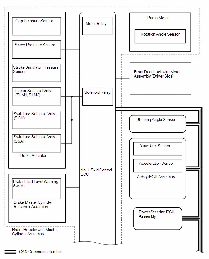
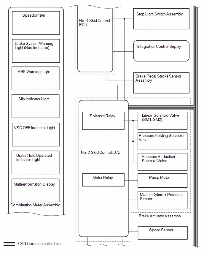
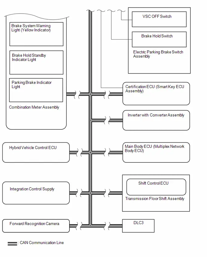
System Diagram
SYSTEM DIAGRAM
How To Proceed With Troubleshooting
CAUTION / NOTICE / HINT
HINT:
*: Use the GTS.
PROCEDURE
| 1. | VEHICLE BROUGHT TO WORKSHOP |
|

| 2. | CUSTOMER PROBLEM ANALYSIS |
(a) Interview the customer and confirm the problem.
Click here

|

| 3. | CHECK DTC, FREEZE FRAME DATA AND Toyota Prius Vehicle CONTROL HISTORY (RoB)* |
(a) Check and record DTCs and Freeze Frame Data.
for DTC Check / Clear: Click here

for Freeze Frame Data: Click here

(b) Clear the DTCs and Freeze Frame Data.
for DTC Check / Clear: Click here

for Freeze Frame Data: Click here

(c) Reconfirm the DTCs.
(1) Reconfirm the DTCs based on the recorded DTCs and Freeze Frame Data.
for DTC Check / Clear: Click here

for Freeze Frame Data: Click here

HINT:
-
When CAN communication system DTCs are output, repair the CAN communication system first.
for HEV Model: Click here

for PHEV Model: Click here

-
If DTCs related to momentary interruptions are output, perform troubleshooting for those DTCs first.
Click here

-
If the GTS cannot communicate with the skid control ECU, inspect the CAN communication system.
for HEV Model: Click here

for PHEV Model: Click here

-
If there is no response from the No. 1 skid control ECU (brake booster with master cylinder assembly) or No. 2 skid control ECU (brake actuator assembly), inspect the supply power circuit.
Click here

(d) Check the Toyota Prius Vehicle Control History (RoB).
Click here

| Tester Display |
|---|
| Vehicle Control History (RoB) |
| Tester Display |
|---|
| Toyota Prius Vehicle Control History (RoB) |
| Tester Display |
|---|
| Vehicle Control History (RoB) |
| Result | Proceed to |
|---|---|
| DTCs are not output. (Problem symptom occurs.) | A |
| DTCs are output. | B |
| DTCs are not output. (Problem symptom does not occur.) | C |
| DTCs are not output. (Toyota Prius Vehicle control history (RoB) is stored.) | D |
| A |

| CONFIRM PROBLEM SYMPTOMS |
| B |

| REPAIR CIRCUITS INDICATED BY OUTPUT DTCS* |
| C |

| USE SIMULATION METHOD TO CHECK |
| D |

| PERFORM TROUBLESHOOTING AND REPAIR REGARDING Toyota Prius Vehicle CONTROL HISTORY (RoB)* NOTICE: After performing troubleshooting and repair regarding vehicle control history (RoB), clear the vehicle control history (RoB). |
Problem Symptoms Table
PROBLEM SYMPTOMS TABLE
If there are no DTCs but the problem still occurs, check the suspected areas for each problem symptom in the order given in the table below and proceed to the relevant troubleshooting page.
HINT:
- Use the table below to help determine the cause of problem symptoms. If multiple suspected areas are listed, the potential causes of the symptoms are listed in order of probability in the "Suspected Area" column of the table. Check each symptom by checking the suspected areas in the order they are listed. Replace parts as necessary.
- Inspect the fuses and relays related to this system before inspecting the suspected areas below.
| Symptom | Suspected Area | Link |
|---|---|---|
| ABS warning light abnormal (Remains on) | Refer to Toyota Prius Vehicle Control History (RoB) |
|
| Refer to Meter / Gauge system |
| |
| Brake system warning light (red indicator) abnormal (Remains on) | Refer to Toyota Prius Vehicle Control History (RoB) |
|
| Refer to Meter / Gauge system |
| |
| Brake system warning light (yellow indicator) abnormal (Remains on) | Refer to Toyota Prius Vehicle Control History (RoB) |
|
| Refer to Meter / Gauge system |
| |
| Brake hold standby indicator light abnormal | Refer to the procedure for "Brake Hold Standby Indicator Light Circuit" |
|
| Brake hold operated indicator light abnormal | Refer to Toyota Prius Vehicle Control History (RoB) |
|
| Refer to the procedure for "Brake Hold Operated Indicator Light Circuit" |
| |
| Slip indicator light abnormal | Refer to Toyota Prius Vehicle Control History (RoB) |
|
| Refer to Meter / Gauge system |
| |
| TRAC does not operate | Refer to the procedure for "TRAC does not Operate" |
|
| Excessive brake pedal travel (No fluid leaks and no air in system) | Refer to the procedure for "Excessive Brake Pedal Travel (No Fluid Leaks and No Air in System)" |
|
| ABS does not operate | Refer to the procedure for "ABS does not Operate" |
|
| ABS operates before necessary when braking | Refer to the procedure for "ABS Operates Before Necessary When Braking" |
|
| VSC does not operate or VSC does not operate correctly | Refer to the procedure for "VSC does not Operate or VSC does not Operate Correctly" |
|
| Abnormal brake pedal response on first depression | Refer to the procedure for "Abnormal Brake Pedal Response on First Depression" |
|
| VSC OFF switch abnormal | Refer to the procedure for "VSC OFF Switch Circuit" |
|
| Meter buzzer abnormal | Refer to Meter / Gauge system |
|


Terminals Of Ecu
TERMINALS OF ECU
CHECK BRAKE BOOSTER WITH MASTER CYLINDER ASSEMBLY
(a) Disconnect the A3 No. 1 skid control ECU (brake booster with master cylinder assembly) connector and measure the voltage or resistance on the wire harness side.
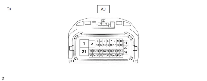
| *a | Front view of wire harness connector (to No. 1 Skid Control ECU (Brake Booster with Master Cylinder Assembly)) | - | - |
NOTICE:
Make sure to wait 5 minutes or more with the ignition switch turned off before removing the integration control supply or disconnecting any supply power circuit from the integration control supply, in order for the voltage to be discharged and self-diagnosis to run.
HINT:
The voltage cannot be measured with the connector connected to the No. 1 skid control ECU (brake booster with master cylinder assembly) as the connector is watertight.
Standard| Terminal No. (Symbol) | Terminal Description | Condition | Specified Condition |
|---|---|---|---|
|
*1: Differs depending on the Toyota Prius vehicle model
*2: Refer to Sub Battery System Click here
| |||
| A3-1 (BM) - Body ground | No. 1 skid control ECU (brake booster with master cylinder assembly) power supply input | Always | 11 to 14 V |
| A3-2 (CBKP) | No. 1 skid control ECU (brake booster with master cylinder assembly) backup power supply input | *2 | *2 |
| A3-3 (CSW2) | No. 2 skid control ECU (brake actuator assembly) operation signal output | - | - |
| A3-4 (CA2H) | CAN communication line 2 (H) | - | - |
| A3-5 | - | - | - |
| A3-6 | - | - | - |
| A3-7 | - | - | - |
| A3-8 | - | - | - |
| A3-9 | - | - | - |
| A3-10 | - | - | - |
| A3-11 (BS) - Body ground | Solenoid power supply input | Always | 11 to 14 V |
| A3-12 | - | - | - |
| A3-13 (CA2L) | CAN communication line 2 (L) | - | - |
| A3-14 | - | - | - |
| A3-15 | - | - | - |
| A3-16 | - | - | - |
| A3-17 | - | - | - |
| A3-18 | - | - | - |
| A3-19 | - | - | - |
| A3-20 | - | - | - |
| A3-21 (GND2) - Body ground | No. 1 skid control ECU (brake booster with master cylinder assembly) ground | 1 minute or more after disconnecting the cable from the negative (-) auxiliary battery terminal | Below 1 Ω |
| A3-22 (CTY) - Body ground | Front door lock with motor assembly input (for driver side) | Driver door closed → open | 11 to 14 V or pulse output (maximum 14 V)*1 → Below 1 V |
| A3-23 (LBL) | Brake fluid level warning switch input | - | - |
| A3-24 (CWKP) - Body ground | Integration control supply operation signal output | *2 | *2 |
| A3-25 | - | - | - |
| A3-26 | - | - | - |
| A3-27 (SKG1) | Brake pedal stroke sensor 1 ground | - | - |
| A3-28 (VSK1) | Brake pedal stroke sensor 1 power supply output | - | - |
| A3-29 (SKS1) | Brake pedal stroke sensor 1 signal input | - | - |
| A3-30 (IGR) - Body ground | IGR power source input | Ignition switch ON | 11 to 14 V |
| A3-31 (STP) - Body ground | Stop light switch assembly input | Stop light switch assembly on → off (Brake pedal depressed → released) | 11 to 14 V → Below 1.5 V |
| A3-32 | - | - | - |
| A3-33 | - | - | - |
| A3-34 (DC1H) | Daisy chain communication line (H) | - | - |
| A3-35 (DC1L) | Daisy chain communication line (L) | - | - |
| A3-36 (CA1H) | CAN communication line 1 (H) | - | - |
| A3-37 (CA1L) | CAN communication line 1 (L) | - | - |
| A3-38 | - | - | - |
| A3-39 | - | - | - |
| A3-40 | - | - | - |
| A3-41 | - | - | - |
| A3-42 | - | - | - |

CHECK BRAKE ACTUATOR ASSEMBLY
(a) Disconnect the A4 No. 2 skid control ECU (brake actuator assembly) connector and measure the voltage or resistance on the wire harness side.
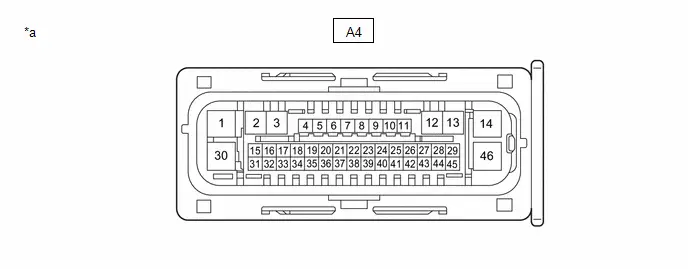
| *a | Front view of wire harness connector (to No. 2 Skid Control ECU (brake actuator assembly)) | - | - |
HINT:
The voltage cannot be measured with the connector connected to the No. 2 skid control ECU (brake actuator assembly) as the connector is watertight.
Standard| Terminal No. (Symbol) | Terminal Description | Condition | Specified Condition |
|---|---|---|---|
| A4-1 (GND1) - Body ground | No. 2 skid control ECU (brake actuator assembly) ground | 1 minute or more after disconnecting the cable from the negative (-) auxiliary battery terminal | Below 1 Ω |
| A4-2 | - | - | - |
| A4-3 | - | - | - |
| A4-4 (RL-) | Rear speed sensor LH (-) signal input | - | - |
| A4-5 (RL ) | Rear speed sensor LH ( ) power supply output | - | - |
| A4-6 (FR-) | Front speed sensor RH (-) signal input | - | - |
| A4-7 (FR ) | Front speed sensor RH ( ) power supply output | - | - |
| A4-8 | - | - | - |
| A4-9 (CSW) - Body ground | VSC OFF switch (electric parking brake switch assembly) input | VSC OFF switch (electric parking brake switch assembly) is pushed → released | Below 1 Ω → 10 kΩ or higher |
| A4-10 (SKS2) | Brake pedal stroke sensor 2 signal input | - | - |
| A4-11 (STP) - Body ground | Stop light switch assembly input | Stop light switch assembly on → off (Brake pedal depressed → released) | 11 to 14 V → Below 1.5 V |
| A4-12 | - | - | - |
| A4-13 | - | - | - |
| A4-14 ( BS) - Body ground | ABS solenoid relay power supply input | Always | 11 to 14 V |
| A4-15 (IG2) - Body ground | IG2 power source input | Ignition switch ON | 11 to 14 V |
| A4-16 (CA2H) | CAN communication line 2 (H) | - | - |
| A4-17 (CA2L) | CAN communication line 2 (L) | - | - |
| A4-18 (SP1) | Speed sensor signal output | - | - |
| A4-19 (RR-) | Rear speed sensor RH (-) signal input | - | - |
| A4-20 (RR ) | Rear speed sensor RH ( ) power supply output | - | - |
| A4-21 (FL-) | Front speed sensor LH (-) signal input | - | - |
| A4-22 (FL ) | Front speed sensor LH ( ) power supply output | - | - |
| A4-23 | - | - | - |
| A4-24 | - | - | - |
| A4-25 (VSK2) | Brake pedal stroke sensor 2 power supply output | - | - |
| A4-26 (SKG2) | Brake pedal stroke sensor 2 ground | - | - |
| A4-27 (CANH) | CAN communication line (H) | - | - |
| A4-28 | - | - | - |
| A4-29 (CTY) - Body ground | No. 2 Skid control ECU (brake actuator assembly) operation signal input | Ignition switch ON | 11 to 14 V |
| A4-30 (GND2) - Body ground | ABS motor ground | 1 minute or more after disconnecting the cable from the negative (-) auxiliary battery terminal | Below 1 Ω |
| A4-31 | - | - | - |
| A4-32 (STPO) - Body ground | Stop light control relay (stop light switch assembly) output | Always | 11 to 14 V |
| A4-33 | - | - | - |
| A4-34 | - | - | - |
| A4-35 (BH) - Body ground | Brake hold switch (electric parking brake switch assembly) input | Brake hold switch (electric parking brake switch assembly) is pushed → released | Below 1 Ω → 10 kΩ or higher |
| A4-36 | - | - | - |
| A4-37 (STP2) - Body ground | Stop light control relay (stop light switch assembly) input | Stop light switch assembly on → off (Brake pedal depressed → released) | 11 to 14 V → Below 1.5 V |
| A4-38 | - | - | - |
| A4-39 | - | - | - |
| A4-40 | - | - | - |
| A4-41 | - | - | - |
| A4-42 | - | - | - |
| A4-43 (CANL) | CAN communication line (L) | - | - |
| A4-44 | - | - | - |
| A4-45 (IG1) - Body ground | IG1 power source input | Ignition switch ON | 11 to 14 V |
| A4-46 (BM) - Body ground | ABS motor relay power supply input | Always | 11 to 14 V |
Diagnosis System
DIAGNOSIS SYSTEM
OBD II

When troubleshooting OBD II (On-Board Diagnostics) vehicles, the vehicle must be connected to the scan tool (complying with SAE J1978). Various data in the vehicle's computer can then be read.
OBD II regulations require that the Toyota Prius vehicle's on-board computer store an SAE code and illuminate the Malfunction Indicator Lamp (MIL) on the instrument panel when the computer detects a malfunction.
Dtc Check / Clear
DTC CHECK / CLEAR
HINT:
- DTCs which are stored in the skid control ECU can be displayed on the GTS. The GTS can display the confirmed and permanent DTCs.
- If a malfunction is detected during the current driving cycle, confirmed and permanent DTCs are stored.
- Confirmed DTCs can be cleared by using the GTS. However, permanent DTCs cannot be cleared using the GTS.
-
After clearing confirmed DTCs using the GTS, permanent DTCs can be cleared when the system is determined to be normal for the relevant DTCs and then the universal trip is performed. The driving pattern to obtain a normal judgment is described under the "Confirmation Driving Pattern" for the respective DTC.
To clear permanent DTCs, all of the following conditions must be are met:
- There is a history that universal trip driving was performed.
- The Toyota Prius vehicle has been judged as normal for 1 trip.
- No malfunctions are detected.
| *: Including 2 trip detection | ||
| Confirmed DTC* | Store condition | Malfunction detected |
| Clear condition | No malfunctions in 40 driving cycles or DTCs cleared using GTS | |
| Permanent DTC* | Store condition | Malfunction detected |
| Clear condition | Ignition switch is turned to ON (READY) after normal judgment obtained in 3 consecutive driving cycles or After DTCs cleared using GTS, universal trip performed and normal judgment obtained for 1 trip | |
| MIL | ON | Malfunction detected |
| OFF | Ignition switch is turned to ON (READY) after normal judgment obtained in 3 consecutive driving cycles or DTCs cleared using GTS | |
HINT:
- Obtaining a normal judgment and performing a universal trip driving pattern can be done in the same driving cycle or in different driving cycles.
- Ensure to wait at least 4 minutes between each trip.
CHECK DTC
(a) Turn the ignition switch off.
(b) Connect the GTS to the DLC3.
(c) Turn the ignition switch to ON.
(d) Turn the GTS on.
(e) Enter the following menus: Chassis / Brake Booster / Trouble Codes.
Chassis > Brake Booster > Trouble Codes(f) Enter the following menus: Chassis / Brake/EPB* / Trouble Codes.
*: Electric Parking Brake System
Chassis > Brake/EPB > Trouble Codes(g) Check the DTC(s) and Freeze Frame Data, and then write them down.
NOTICE:
The electronically controlled brake system outputs DTCs for the following system. When DTCs other than those in Diagnostic Trouble Code Chart for the electronically controlled brake system are output, refer to Diagnostic Trouble Code Chart for the relevant system.
| System | Proceed to |
|---|---|
| Electric Parking Brake System |
|
| GTS Display | Description |
|---|---|
| *: Including 2 trip detection | |
| Test Failed | Shows the malfunction judgment results during the current trip. |
| Confirmed* | Shows the DTCs confirmed up to now. (The number of current trips differs for each DTC.) |
(h) Check the details of the DTC(s).
CLEAR DTC (CONFIRMED DTC)
(a) Turn the ignition switch off.
(b) Connect the GTS to the DLC3.
(c) Turn the ignition switch to ON.
(d) Turn the GTS on.
(e) Enter the following menus: Chassis / Brake Booster / Trouble Codes.
Chassis > Brake Booster > Clear DTCs(f) Enter the following menus: Chassis / Brake/EPB* / Trouble Codes.
*: Electric Parking Brake System
Chassis > Brake/EPB > Clear DTCs(g) Press the clear button.
- After clearing confirmed DTCs using the GTS, permanent DTCs can be cleared when the universal trip is performed and then the system is determined to be normal for the relevant DTCs. The driving pattern to obtain a normal judgment is described under the "Confirmation Driving Pattern" for the respective DTC.
-
To clear permanent DTCs, all of the following conditions must be are met:
- There is a history that universal trip driving was performed.
- The Toyota Prius vehicle has been judged as normal for 1trip.
- No malfunctions are detected.
CLEAR PERMANENT DTC
NOTICE:
When performing the following procedure, make sure that the driver door is closed and is not opened at any time during the procedure.
(a) Turn the ignition switch off.
(b) Connect the GTS to the DLC3.
(c) Turn the ignition switch to ON.
(d) Turn the GTS on.
(e) Enter the following menus: Chassis / Brake Booster / Trouble Codes.
Chassis > Brake Booster > Trouble CodesHINT:
If "PERMANENT" in the top right of the screen displays "YES", permanent DTCs are stored.
(f) Enter the following menus: Chassis / Brake/EPB* / Trouble Codes.
*: Electric Parking Brake System
Chassis > Brake/EPB > Trouble CodesHINT:
If "PERMANENT" in the top right of the screen displays "YES", permanent DTCs are stored.
(g) Select the "Generic" tab.
(h) Check if permanent DTCs are stored.
HINT:
If permanent DTCs are not output, it is not necessary to continue this procedure.
(i) Clear the DTCs (even if no DTCs are stored, perform the clear DTC procedure).
Chassis > Brake Booster > Clear DTCs Chassis > Brake/EPB > Clear DTCsNOTICE:
Do not clear the DTCs or disconnect the cable from the auxiliary battery terminal after performing this step.
(j) Turn the ignition switch off and wait for 4 minutes or more.
(k) Perform the universal trip.
HINT:
The driving pattern to obtain a normal judgment and the universal trip driving can be performed consecutively in the same driving cycle.
- Turn the ignition switch to ON (READY) and wait for 30 seconds or more.
-
With the engine running, drive the Toyota Prius vehicle at 40 km/h (25 mph) or more for a total of 5 minutes or more.
CAUTION:
When performing a driving pattern, obey all speed limits and traffic laws.
HINT:
It is possible to complete the drive pattern even if the vehicle decelerates to less than 40 km/h (25 mph) during the driving cycle provided that the Toyota Prius vehicle is driven at 40 km/h (25 mph) or more for a total of 5 minutes.
- Allow 10 minutes or more to elapse from the time the ignition switch turned to ON (READY).
(l) Turn the ignition switch off and wait for 4 minutes or more.
(m) Turn the ignition switch to ON (READY).
(n) Perform the normal judgment procedure in the respective confirmation driving pattern of each output DTC.
HINT:
Do not turn the ignition switch off by mistake during this step.
(o) With the ignition switch ON (READY) wait for 5 seconds or more. (Except when the ignition switch is already turned to ON (READY) or the engine is running)
(p) Turn the ignition switch off and wait for 4 minutes or more.
(q) Turn the ignition switch to ON (READY).
(r) Enter the following menus: Chassis / Brake Booster / Trouble Codes.
Chassis > Brake Booster > Trouble Codes(s) Enter the following menus: Chassis / Brake/EPB* / Trouble Codes.
*: Electric Parking Brake System
Chassis > Brake/EPB > Trouble Codes(t) Check that the permanent DTCs have been cleared.
Freeze Frame Data
FREEZE FRAME DATA
FREEZE FRAME DATA
(a) Using the GTS, check the vehicle condition (ECU, sensor) when a DTC is output.
CHECK FREEZE FRAME DATA WHEN DTC WAS STORED
(a) Freeze Frame Data is stored when a DTC is output.
(b) Once Freeze Frame Data is stored when a DTC is output, it is not updated or cleared until the DTC is cleared.
(c) Check the Freeze Frame Data when a DTC is output.
(1) Turn the ignition switch off.
(2) Connect the GTS to the DLC3.
(3) Turn the ignition switch to ON.
(4) Turn the GTS on.
(5) Enter the following menus: Chassis / Brake Booster / Trouble Codes.
Chassis > Brake Booster > Trouble Codes(6) Enter the following menus: Chassis / Brake/EPB* / Trouble Codes.
*: Electric Parking Brake System
Chassis > Brake/EPB > Trouble Codes(7) Select a DTC to display the Freeze Frame Data.
(8) Check the Freeze Frame Data for the output DTC.
Chassis > Brake Booster| Tester Display | Measurement Item | Range | Normal Condition | Diagnostic Note |
|---|---|---|---|---|
| Total Distance Traveled - Unit | Total distance traveled unit | km / mile | - | - |
| Total Distance Traveled | Total distance traveled | Min.: 0 Max.: 16777215 | - | - |
| Solenoid Power Supply Voltage | Solenoid power supply voltage value | Min.: 0.0 V Max.: 25.5 V | - | Changes in proportion to auxiliary battery voltage |
| Stop Light SW | Stop light switch assembly (STP terminal input) | OFF / ON | OFF: Brake pedal released ON: Brake pedal depressed | HINT: The brake pedal state is determined using the voltage at terminal STP |
| Parking Brake SW | Parking brake status | OFF / ON | OFF: Parking brake released ON: Parking brake applied | - |
| Buzzer | Meter buzzer | OFF / ON | OFF: Buzzer off ON: Buzzer on | - |
| Dealer Mode | Dealer Mode (Signal Check mode or Calibration mode) status | OFF / ON | OFF: Normal mode ON: Dealer Mode (Signal Check mode or Calibration mode) | HINT:
|
| Reservoir Warning SW | Brake fluid level warning switch | OFF / ON | OFF: Reservoir level normal ON: Reservoir level low | - |
| ECB Solenoid (SGH) | Switching solenoid valve (SGH) | OFF / ON | OFF: Solenoid off ON: Solenoid on | ECB: Electronically Controlled Brake System |
| ECB Solenoid (SSA) | Switching solenoid valve (SSA) | OFF / ON | OFF: Solenoid off ON: Solenoid on | ECB: Electronically Controlled Brake System |
| IGP_PT2 | IGP_PT2 status | OFF / ON | OFF: IGP_PT2 OFF ON: IGP_PT2 ON | - |
| Stop Switch Open | Momentary interruption (open circuit) status in wire harness between No. 1 skid control ECU (brake booster with master cylinder assembly) and stop light switch assembly status | Normal / Under intermittent | Normal: Normal Under intermittent: Momentary interruption | - |
| Stroke Open | Brake pedal stroke sensor 1 open detection | Normal / Under intermittent | Normal: Normal Under intermittent: Momentary interruption | - |
| Servo Pressure Sensor Open | Servo pressure sensor open detection | Normal / Under intermittent | Normal: Normal Under intermittent: Momentary interruption | - |
| Gap Hold Chamber Pressure Sensor Open | Gap pressure sensor open detection | Normal / Under intermittent | Normal: Normal Under intermittent: Momentary interruption | - |
| Stroke Sensor | Brake pedal stroke sensor 1 | Min.: 0.0 V Max.: 5.0 V | Brake pedal released: 0.6 to 1.4 V | Reading increases when brake pedal is depressed |
| Quantity of Brake Pedal Stroke | Brake pedal stroke amount | Min.: 0 mm Max.: 255 mm | Brake pedal released: 0 mm | Reading increases when brake pedal is depressed |
| Servo Pressure | Pressure value of servo | Min.: 0.00 MPa Max.: 24.48 MPa | 0.00 to 21.60 MPa | Brake pedal is being depressed: Changes in proportion to the depression force of the brake pedal Brake pedal released: 0.00 to 1.53 MPa |
| Voltage of Stroke Sensor | Voltage of brake pedal stroke sensor 1 | Min.: 0.0 V Max.: 5.0 V | - | - |
| Brake Pedal Stroke Change Speed | Brake pedal stroke rate of change | Min.: -2560 mm/s Max.: 2540 mm/s | Brake pedal released or depressed and held: 0 mm/s | Brake pedal is being moved: Changes in proportion to the operation speed of the brake pedal |
| Target Oil Pressure | Wheel target hydraulic pressure | Min.: 0.00 MPa Max.: 20.00 MPa | - | Changes according to the target wheel cylinder hydraulic pressure |
| VCSK Voltage Value | VCSK voltage value | Min.: 0.000 V Max.: 5.500 V | 4.800 to 5.200 V | - |
| SGH Solenoid Current | Switching solenoid valve (SGH) current | Min.: 0.000 A Max.: 3.000 A | 0.000 to 1.500 A | - |
| SSA Solenoid Current | Switching solenoid valve (SSA) current | Min.: 0.000 A Max.: 3.000 A | 0.000 to 1.500 A | - |
| The Number of Capacitor Operation | Displays the number of integration control supply operations | Min.: 0 Max.: 255 | - | - |
| Gap Hold Chamber Oil Pressure | Pressure value of stroke simulator | Min.: 0.00 MPa Max.: 24.48 MPa | Brake pedal released: 0.00 to 1.53 MPa | Brake pedal is being depressed: Changes in proportion to the depression force of the brake pedal |
| Gap Hold Chamber Oil Pressure Grade | Amount of change in stroke simulator oil pressure | Min.: -30 MPa/s Max.: 225 MPa/s | - | - |
| Linear Solenoid Current (SLM1) | Linear solenoid valve (SLM1) current | Min.: 0.000 A Max.: 1.500 A | Brake pedal released: 0 A | - |
| Linear Solenoid Current (SLM2) | Linear solenoid valve (SLM2) current | Min.: 0.000 A Max.: 1.500 A | Brake pedal released: 0 A | - |
| IGR Voltage | IGR voltage value | Min.: 0.0 V Max.: 25.5 V | - | Changes in proportion to auxiliary battery voltage |
| BS Voltage | BS voltage value | Min.: 0.0 V Max.: 25.5 V | - | Changes in proportion to auxiliary battery voltage |
| BM Voltage | BM voltage value | Min.: 0.0 V Max.: 25.5 V | - | Changes in proportion to auxiliary battery voltage |
| Zero point Calibrated Value of Phase U Current Monitor | Displays zero point calibrated value of phase U current monitor for brushless motor | Min.: -32.768 A Max.: 32.767 A | - | - |
| Zero point Calibrated Value of Phase V Current Monitor | Displays zero point calibrated value of phase V current monitor for brushless motor | Min.: -32.768 A Max.: 32.767 A | - | - |
| Zero point Calibrated Value of Phase W Current Monitor | Displays zero point calibrated value of phase W current monitor for brushless motor | Min.: -32.768 A Max.: 32.767 A | - | - |
| Thermistor1 Temperature for Inverter Circuit | Temperature of thermistor1 in inverter circuit | Min.: -327.68°C (-558°F) Max.: 327.67°C (622°F) | - | - |
| Thermistor2 Temperature for Inverter Circuit | Temperature of thermistor2 in inverter circuit | Min.: -327.68°C (-558°F) Max.: 327.67°C (622°F) | - | - |
| Brushless Motor Inverter end Voltage | Inverter end voltage for brushless motor | Min.: 0.00 V Max.: 655.35 V | - | Changes in proportion to auxiliary battery voltage |
| Brushless Motor Required Rotation Speed (with Rotation Angle Sensor) | Requested brushless motor rotation speed | Min.: -32768 rpm Max.: 32767 rpm | Brake pedal released: 0 rpm | - |
| Brushless Motor Actual Rotation Speed (with Rotation Angle Sensor) | Actual brushless motor rotation speed | Min.: -32768 rpm Max.: 32767 rpm | Brake pedal released: 0 rpm | - |
| Brushless Motor Operation Status (with Rotation Angle Sensor) | Operation status of brushless motor | Abnormal / Stop / Synchronization drive / Extended Induced voltage | - | - |
| Down Stream Voltage Solenoid Relay | Solenoid relay downstream voltage | Min.: 0.0 V Max.: 25.5 V | - | Changes in proportion to auxiliary battery voltage |
| CBKP Voltage | CBKP voltage value | Min.: 0.0 V Max.: 25.5 V | - | Changes in proportion to auxiliary battery voltage |
-
*1: for performing Dealer Mode (Signal Check): Click here

-
*2: for entering Dealer Mode (Calibration): Click here

| Tester Display | Measurement Item | Range | Normal Condition | Diagnostic Note |
|---|---|---|---|---|
| Total Distance Traveled - Unit | Total distance traveled unit | km / mile | - | - |
| Total Distance Traveled | Total distance traveled | Min.: 0 Max.: 16777215 | - | - |
| FR Wheel Speed | Front wheel speed sensor RH reading | Min.: 0.0 km/h (0 mph) Max.: 6553.5 km/h (4072 mph) | Toyota Prius Vehicle stopped: 0.0 km/h (0 mph) | When driving at constant speed: No large fluctuations |
| FL Wheel Speed | Front wheel speed sensor LH reading | Min.: 0.0 km/h (0 mph) Max.: 6553.5 km/h (4072 mph) | Toyota Prius Vehicle stopped: 0.0 km/h (0 mph) | When driving at constant speed: No large fluctuations |
| RR Wheel Speed | Rear wheel speed sensor RH reading | Min.: 0.0 km/h (0 mph) Max.: 6553.5 km/h (4072 mph) | Toyota Prius Vehicle stopped: 0.0 km/h (0 mph) | When driving at constant speed: No large fluctuations |
| RL Wheel Speed | Rear wheel speed sensor LH reading | Min.: 0.0 km/h (0 mph) Max.: 6553.5 km/h (4072 mph) | Toyota Prius Vehicle stopped: 0.0 km/h (0 mph) | When driving at constant speed: No large fluctuations |
| Master Cylinder Sensor 1 | Master cylinder pressure sensor pressure (value detected by ECU) | Min.: -1.00 MPa Max.: 23.99 MPa | Brake pedal released: -1.00 to 0.00 MPa | Reading increases when brake pedal is depressed |
| Master Cylinder Sensor Temperature | Master cylinder pressure sensor temperature | Min.: -80°C (-112°F) Max.: 175°C (347°F) | Current master cylinder pressure sensor temperature | - |
| M/C Sensor Grade | Master cylinder pressure sensor change (value detected by ECU) | Min.: -30 MPa/s Max.: 225 MPa/s | Brake pedal released or pedal held at constant position: 0 MPa/s | When brake pedal is being operated: Changes in proportion with the pedal movement speed |
| Lateral G | Lateral G | Min.: -25.105 m/s2 Max.: 24.908 m/s2 | Turning right: -25.105 to 0.000 m/s2 Turning left: 0.000 to 24.908 m/s2 | During turning: Changes in proportion with lateral acceleration |
| Forward and Rearward G | Forward and rearward G | Min.: -25.105 m/s2 Max.: 24.908 m/s2 | During deceleration: -25.105 to 0.000 m/s2 During acceleration: 0.000 to 24.908 m/s2 | During acceleration/deceleration: Changes in proportion with acceleration |
| Yaw Rate Sensor Value | Yaw rate sensor value | Min.: -128°/s Max.: 127°/s | Toyota Prius Vehicle stopped: 0°/s Turning right: -128 to 0°/s Turning left: 0 to 127°/s | - |
| Steering Angle Value | Steering angle sensor value | Min.: -3276.8° Max.: 3276.7° | Turning left: 0.0 to 3276.7° Turning right: -3276.8 to 0.0° | - |
| Zero Point of Steering Angle | Zero point of steering angle | Min.: -3276.8° Max.: 3276.7° | - | - |
| MT Voltage Value | ABS motor drive voltage value | Min.: 0.0 V Max.: 25.5 V | - | Changes in proportion to auxiliary battery voltage HINT: This is the voltage downstream of the ABS motor as monitored by the No. 2 skid control ECU (brake actuator assembly) |
| Solenoid Power Supply Voltage | Solenoid power supply voltage value | Min.: 0.0 V Max.: 25.5 V | - | Changes in proportion to auxiliary battery voltage HINT: This is the voltage output (which supplies power to each solenoid) from the No. 2 skid control ECU (brake actuator assembly) to the ABS solenoid relay |
| Accelerator Opening Angle % | Percentage of accelerator pedal opening angle | Min.: 0.0% Max.: 127.5% | Accelerator pedal released: 0.0% | During accelerator pedal operation: Changes in proportion with the pedal movement |
| Shift Lever Position | Shift position information | fail / 1st / 2nd / 3rd / 4th / 5th / 6th / B / D/M / N / P / R / No input | Actual shift position | - |
| TRC(TRAC)/VSC OFF Mode | TRAC/VSC off mode | Normal mode (TRC(TRAC) ON/VSC ON) / TRC(TRAC) OFF mode (TRC(TRAC) OFF/VSC ON) / VSC expert mode (VSC expert mode MID ON) / VSC OFF mode (TRC(TRAC) OFF/VSC OFF) | Normal mode (TRC(TRAC) ON/VSC ON): Normal mode TRC(TRAC) OFF mode (TRC(TRAC) OFF/VSC ON): TRAC off mode VSC expert mode (VSC expert mode MID ON): VSC expert mode VSC OFF mode (TRC(TRAC) OFF/VSC OFF): VSC off mode | - |
| Brake Hold Control Mode | Brake hold control mode | Out of control mode / Pressure hold mode / Pressure release mode / EPB lock mode | Out of control mode: Brake hold control system is off or brake hold control system is stand-by mode (brake hold standby indicator light is illuminated) Pressure hold mode: Brake hold control is operating (brake hold operated indicator light is illuminated) Pressure release mode: Brake hold control is released (brake hold operated indicator light not illuminated) EPB lock mode: Parking brake is engaged during brake hold control | HINT:
|
| FR Target Oil Pressure | Front wheel RH target oil pressure | Min.: 0.0 MPa Max.: 20.0 MPa | - | Different according to target oil pressure of each wheel |
| FL Target Oil Pressure | Front wheel LH target oil pressure | Min.: 0.0 MPa Max.: 20.0 MPa | - | Different according to target oil pressure of each wheel |
| RR Target Oil Pressure | Rear wheel RH target oil pressure | Min.: 0.0 MPa Max.: 20.0 MPa | - | Different according to target oil pressure of each wheel |
| RL Target Oil Pressure | Rear wheel LH target oil pressure | Min.: 0.0 MPa Max.: 20.0 MPa | - | Different according to target oil pressure of each wheel |
| Toyota Prius Vehicle Speed | Vehicle speed (estimated vehicle speed used for various controls) | Min.: 0.0 km/h (0 mph) Max.: 6553.5 km/h (4072 mph) | Vehicle stopped: 0.0 km/h (0 mph) | When driving at constant speed: No large fluctuations |
| Toyota Prius Vehicle Speed Grade | Vehicle acceleration/deceleration | Min.: -25.105 m/s2 Max.: 24.908 m/s2 | Vehicle stopped: 0.000 m/s2 During deceleration: -25.105 to 0.000 m/s2 During acceleration: 0.000 to 24.908 m/s2 | During driving: Changes in proportion with Toyota Prius vehicle acceleration/deceleration |
| Vehicle Stop Time from IG ON | Time vehicle stopped after ignition switch turned to ON | Min.: 0 s Max.: 1275 s | - | - |
| Travel Distance from IG ON | Driving time after ignition switch turned to ON | Min.: 0 s Max.: 1275 s | - | - |
| Stop Light SW | Stop light switch assembly status (STP or STP2 terminal input) | OFF / ON | OFF: Brake pedal released ON: Brake pedal depressed | HINT:
|
| Parking Brake SW | Parking brake status | OFF / ON | OFF: Parking brake released ON: Parking brake applied | - |
| Brake Hold Switch | Brake hold switch (electric parking brake switch assembly) (BH terminal input) | OFF / ON | OFF: Brake hold switch (electric parking brake switch assembly) OFF ON: Brake hold switch (electric parking brake switch assembly) ON | HINT: The brake hold switch (electric parking brake switch assembly) state is determined using the voltage at terminal BH |
| Stop Light Relay | Stop light control relay (stop light switch assembly) status (STP terminal input) | OFF / ON | OFF: Stop light control relay (stop light switch assembly) off and brake pedal released ON: Stop light control relay (stop light switch assembly) on or brake pedal depressed | HINT: The voltage of power supplied to the stop lights is measured at the STP terminal. |
| Inspection Mode | Inspection mode | OFF / ON | OFF: Normal mode ON: Inspection mode | - |
| TRC(TRAC) Control | TRAC control status | Out of controlling / Under Controlling | Out of controlling: Not during control Under Controlling: During control | - |
| TRC(TRAC) Engine Control | TRAC throttle control status | Out of controlling / Under Controlling | Out of controlling: Not during control Under Controlling: During control | - |
| TRC(TRAC) Brake Control | TRAC brake control status | Out of controlling / Under Controlling | Out of controlling: Not during control Under Controlling: During control | - |
| FR Wheel VSC Ctrl Status | Front wheel RH VSC control status | Out of controlling / Under Controlling | Out of controlling: Not during control Under Controlling: During control | - |
| FL Wheel VSC Ctrl Status | Front wheel LH VSC control status | Out of controlling / Under Controlling | Out of controlling: Not during control Under Controlling: During control | - |
| RR Wheel VSC Ctrl Status | Rear wheel RH VSC control status | Out of controlling / Under Controlling | Out of controlling: Not during control Under Controlling: During control | - |
| RL Wheel VSC Ctrl Status | Rear wheel LH VSC control status | Out of controlling / Under Controlling | Out of controlling: Not during control Under Controlling: During control | - |
| FR Wheel ABS Ctrl Status | Front wheel RH ABS control status | Out of controlling / Under Controlling | Out of controlling: Not during control Under Controlling: During control | - |
| FL Wheel ABS Ctrl Status | Front wheel LH ABS control status | Out of controlling / Under Controlling | Out of controlling: Not during control Under Controlling: During control | - |
| RR Wheel ABS Ctrl Status | Rear wheel RH ABS control status | Out of controlling / Under Controlling | Out of controlling: Not during control Under Controlling: During control | - |
| RL Wheel ABS Ctrl Status | Rear wheel LH ABS control status | Out of controlling / Under Controlling | Out of controlling: Not during control Under Controlling: During control | - |
| BA Ctrl Status | BA control status | OFF / ON | OFF: Not during control ON: During control | - |
| PBA Ctrl Status | PBA control status | OFF / ON | OFF: Not during control ON: During control | - |
| Stop Light Relay State for ECU Control | Stop light control relay (stop light switch assembly) status (STPO terminal output) (for ECU control) | OFF / ON | OFF: Stop light control relay (stop light switch assembly) off (Stop light off) ON: Stop light control relay (stop light switch assembly) on (Stop light on) | - |
| Solenoid State for ECU Control | ABS solenoid relay status (for ECU control) | OFF / ON | OFF: ABS solenoid relay not operating ON: ABS solenoid relay operating | - |
| Motor State for ECU Control | ABS motor relay status (for ECU control) | OFF / ON | OFF: ABS motor relay not operating ON: ABS motor relay operating | - |
| Buzzer | Meter buzzer | OFF / ON | OFF: Buzzer off ON: Buzzer on | - |
| Dealer Mode | Dealer Mode (Signal Check mode or Calibration mode) status | OFF / ON | OFF: Normal mode ON: Dealer Mode (Signal Check mode or Calibration mode) | HINT:
|
| Zero Point Memory State of Steering Angle Sensor | Steering angle sensor zero point memorization status | Zero point is not memorized / Zero point is memorized | - | HINT: The steering angle sensor zero point is acquired when the Toyota Prius vehicle is being driven in a straight line at a speed of 35 km/h (22 mph) or more for approximately 5 seconds. |
| Regenerative Cooperation | Regenerative cooperation | OFF / ON | OFF: Not operating ON: Operating | - |
| TRC(TRAC)/VSC OFF SW | VSC OFF switch (electric parking brake switch assembly) (CSW terminal input) | OFF / ON | OFF: VSC OFF switch (electric parking brake switch assembly) OFF ON: VSC OFF switch (electric parking brake switch assembly) ON | HINT: The VSC OFF switch (electric parking brake switch assembly) state is determined using the voltage at terminal CSW |
| IGP_PT2 | IGP_PT2 status | OFF / ON | OFF: IGP_PT2 OFF ON: IGP_PT2 ON | - |
| FR Wheel | Front right wheel rotation direction | Forward / Back | When driving forward: forward When reversing: Back | - |
| FL Wheel | Front left wheel rotation direction | Forward / Back | When driving forward: forward When reversing: Back | - |
| RR Wheel | Rear right wheel rotation direction | Forward / Back | When driving forward: forward When reversing: Back | - |
| RL Wheel | Rear left wheel rotation direction | Forward / Back | When driving forward: forward When reversing: Back | - |
| FR Speed Open | Front speed sensor RH open detection | Normal / Under intermittent | Normal: Normal Under intermittent: Momentary interruption | - |
| FL Speed Open | Front speed sensor LH open detection | Normal / Under intermittent | Normal: Normal Under intermittent: Momentary interruption | - |
| RR Speed Open | Rear speed sensor RH open detection | Normal / Under intermittent | Normal: Normal Under intermittent: Momentary interruption | - |
| RL Speed Open | Rear speed sensor LH open detection | Normal / Under intermittent | Normal: Normal Under intermittent: Momentary interruption | - |
| Yaw Rate Open | Yaw rate sensor (airbag ECU assembly) open detection | Normal / Under intermittent | Normal: Normal Under intermittent: Momentary interruption | - |
| Deceleration Open | Acceleration sensor (airbag ECU assembly) open detection | Normal / Under intermittent | Normal: Normal Under intermittent: Momentary interruption | - |
| Steering Open | Steering angle sensor open detection | Normal / Under intermittent | Normal: Normal Under intermittent: Momentary interruption | - |
| Master Cylinder Open | Master cylinder pressure sensor open detection | Normal / Under intermittent | Normal: Normal Under intermittent: Momentary interruption | - |
| FR Speed Sensor Voltage Open | Front speed sensor RH voltage open detection | Normal / Under intermittent | Normal: Normal Under intermittent: Momentary interruption | - |
| FL Speed Sensor Voltage Open | Front speed sensor LH voltage open detection | Normal / Under intermittent | Normal: Normal Under intermittent: Momentary interruption | - |
| RR Speed Sensor Voltage Open | Rear speed sensor RH voltage open detection | Normal / Under intermittent | Normal: Normal Under intermittent: Momentary interruption | - |
| RL Speed Sensor Voltage Open | Rear speed sensor LH voltage open detection | Normal / Under intermittent | Normal: Normal Under intermittent: Momentary interruption | - |
| M/C Pressure Sensor Noise | Master cylinder pressure sensor noise detection | Normal / Under intermittent | Normal: Noise is not detected Under intermittent: Noise is detected | - |
| Yaw Rate Sensor Voltage Open | Yaw rate sensor (airbag ECU assembly) voltage open detection | Normal / Under intermittent | Normal: Normal Under intermittent: Momentary interruption | - |
| Master Cylinder Pressure Sensor Power Supply Open | Master cylinder pressure sensor power supply voltage status | Normal / Under intermittent | Normal: Normal Under intermittent: Momentary interruption | - |
| Solenoid Power Supply Open | Solenoid power supply voltage status | Normal / Under intermittent | Normal: Normal Under intermittent: Momentary interruption | - |
| Motor Power Supply Open | Motor power supply voltage status | Normal / Under intermittent | Normal: Normal Under intermittent: Momentary interruption | - |
| Stop Switch Open | Momentary interruption (open circuit) status in wire harness between No. 2 skid control ECU (brake actuator assembly) and stop light switch assembly status | Normal / Under intermittent | Normal: Normal Under intermittent: Momentary interruption | - |
| A/C ECU Communication Open | Air conditioning amplifier assembly communication open detection | Normal / Under intermittent | Normal: Momentary interruption not detected Under intermittent: Momentary interruption detected | - |
| Air Bag ECU Communication Open | Airbag ECU assembly open detection | Normal / Under intermittent | Normal: Normal Under intermittent: Momentary interruption | - |
| Stroke2 Open | Brake pedal stroke sensor 2 open detection | Normal / Under intermittent | Normal: Normal Under intermittent: Momentary interruption | - |
| HV Communication Open | Hybrid Toyota Prius vehicle control ECU communication open detection | Normal / Under intermittent | Normal: Normal Under intermittent: Momentary interruption | - |
| Body ECU Communication Open | Main body ECU (multiplex network body ECU) communication open detection | Normal / Under intermittent | Normal: Normal Under intermittent: Momentary interruption | - |
| Brake Hold Ready | Brake hold control permission status | Not in stand-by mode / Stand-by mode | Not in stand-by mode: Brake hold function not operating (brake hold standby indicator light not illuminated) Stand-by mode: Brake hold function stand-by state (brake hold standby indicator light illuminated) | - |
| Stroke Sensor2 | Brake pedal stroke sensor 2 | Min.: 0.0 V Max.: 5.0 V | Brake pedal released: 3.6 to 4.4 V | Reading decreases when brake pedal is depressed |
| Quantity of Brake Pedal Stroke | Brake pedal stroke amount | Min.: 0 mm Max.: 255 mm | Brake pedal released: 0 mm | Reading increases when brake pedal is depressed |
| Voltage of Stroke Sensor2 | Voltage of brake pedal stroke sensor 2 | Min.: 0.0 V Max.: 5.0 V | - | - |
| FR Regenerative Request | FR regenerative request torque | Min.: 0 Nm Max.: 1048560 Nm | - | Changes according to brake pedal force (When depressing the brake pedal lightly after reaching 30 km/h (19 mph) or more, avoiding sudden braking.) |
| FR Regenerative Operation | FR regenerative operation torque | Min.: 0 Nm Max.: 1048560 Nm | - | Changes according to brake pedal force (When depressing the brake pedal lightly after reaching 30 km/h (19 mph) or more, avoiding sudden braking.) |
| Brake Pedal Stroke Change Speed | Brake pedal stroke rate of change | Min.: -2560 mm/s Max.: 2540 mm/s | Brake pedal released or depressed and held: 0 mm/s | Brake pedal is being moved: Changes in proportion to the operation speed of the brake pedal |
| VCSK Voltage Value | VSK2 voltage value | Min.: 0.000 V Max.: 5.500 V | 4.800 to 5.200 V | - |
| IGR Voltage | IG1 voltage value | Min.: 0.0 V Max.: 25.5 V | - | Changes in proportion to auxiliary battery voltage |
| BS Voltage | BS voltage value | Min.: 0.0 V Max.: 25.5 V | - | Changes in proportion to auxiliary battery voltage |
| BM Voltage | BM voltage value | Min.: 0.0 V Max.: 25.5 V | - | Changes in proportion to auxiliary battery voltage |
| Voltage Difference between Motor Input-Output Terminal | Voltage difference between motor input-output terminal | Min.: -640.00 V Max.: 639.98 V | - | - |
| Yaw Rate Sensor 1 Higher Resolution Signal | Yaw rate sensor 1 higher resolution signal | Min.: -327.68 deg/sec Max.: 327.67 deg/sec | Turning right: -327.68 to 0.00 deg/sec Turning left: 327.68 to 0.00 deg/sec | - |
| Yaw Rate Sensor 2 Higher Resolution Signal | Yaw rate sensor 2 higher resolution signal | Min.: -327.68 deg/sec Max.: 327.67 deg/sec | Turning right: -327.68 to 0.00 deg/sec Turning left: 327.68 to 0.00 deg/sec | - |
| GL1 GX Sensor Higher Resolution Signal | GL1 GX sensor higher resolution signal | Min.: -32768 mG Max.: 32767 mG | During deceleration: -32768 to 0 mG During acceleration: 0 to 32767 mG | - |
| GL2 GY Sensor Higher Resolution Signal | GL2 GY sensor higher resolution signal | Min.: -32768 mG Max.: 32767 mG | Turning right: -32768 to 0 mG Turning left: 0 to 32767 mG | - |
| Brakes Specifications Change by C-BEST | Brakes specifications change by C-BEST | None / Exist | - | - |
| SLM2 Refresh Drive Completed Status | Linear solenoid (SLM2) refresh complete/incomplete | Not Complete / Complete | Complete: Linear solenoid (SLM2) refresh complete Not complete: Linear solenoid (SLM2) refresh incomplete | - |
-
*1: for performing Dealer Mode (Signal Check): Click here

-
*2: for entering Dealer Mode (Calibration): Click here

CLEAR FREEZE FRAME DATA
NOTICE:
Clearing the DTCs will also clear the Freeze Frame Data.
(a) Turn the ignition switch off.
(b) Connect the GTS to the DLC3.
(c) Turn the ignition switch to ON.
(d) Turn the GTS on.
(e) Enter the following menus: Chassis / Brake Booster / Trouble Codes.
Chassis > Brake Booster > Clear DTCs(f) Enter the following menus: Chassis / Brake/EPB* / Trouble Codes.
*: Electric Parking Brake System.
Chassis > Brake/EPB > Clear DTCs(g) Press the clear button.
Signal Check
SIGNAL CHECK
SENSOR CHECK USING DEALER MODE (SIGNAL CHECK)
NOTICE:
- After performing "Calibration", perform a master cylinder pressure sensor check.
- After replacing or removing and installing a speed sensor, perform Dealer Mode (Signal Check) inspection to confirm that the speed sensors are operating correctly.
- After replacing or removing and installing a speed sensor rotor, perform Dealer Mode (Signal Check) inspection to confirm that the speed sensors are operating correctly.
HINT:
- Signals related to the electronically controlled brake system can be inspected by performing a Dealer Mode (Signal Check) inspection. During the inspection, the display of items determined normal by the skid control ECU changes from incomplete to complete.
- During Dealer Mode (Signal Check), the VSC and TRAC do not operate regardless of whether the system is normal or a malfunction is detected.
- If a sensor is malfunctioning, ABS does not operate and the ABS warning light, brake system warning light (yellow indicator) and slip indicator light illuminate.
-
Even during Dealer Mode (Signal Check), if there is a system malfunction that causes brake hold control to be prohibited, when the Toyota Prius vehicle is under the following conditions and the brake hold switch (electric parking brake switch assembly) is turned on, the brake hold operated indicator light blinks.
-
Vehicle Conditions:
- The driver door is closed.
- The driver seat belt is fastened.
-
Vehicle Conditions:
(a) Procedure to Enter Dealer Mode (Signal Check)
(1) Turn the ignition switch off.
(2) Check that the steering wheel is centered.
(3) Check that park (P) is selected.
(4) Connect the GTS to the DLC3.
(5) Turn the ignition switch to ON.
(6) Turn the GTS on.
(7) Switch the skid control ECU to Dealer Mode (Signal Check) using the GTS. Enter the following menus: Chassis / Brake/EPB* / Utility / Signal Check.
*: Electric Parking Brake System
Chassis > Brake/EPB > Utility| Tester Display |
|---|
| Signal Check |
(b) Confirm the system has entered Dealer Mode (Signal Check)
(1) Confirm that the ABS warning light, brake system warning light (yellow indicator) and slip indicator light indicate the Dealer Mode pattern (blinking at 0.25 second intervals).
HINT:
- When in Dealer Mode (signal check), "Traction Control Turned OFF" is displayed on the multi-information display.
- When entering Dealer Mode (Signal Check), if the parking brake is engaged, the parking brake indicator light (red) will illuminate, and if the parking brake is not engaged, the parking brake indicator light (red) will blink in the Dealer Mode pattern (blinking at 0.25 second intervals).
(c) Master Cylinder Pressure Sensor Check
(1) With the Toyota Prius vehicle stopped, release the brake pedal for 1 second or more and check that the value of Dealer Mode (Signal Check) Inspection Item "Output in Master Cylinder Pressure Sensor" changes from incomplete to complete.
HINT:
- The status of the ABS warning light, brake system warning light (yellow indicator) and slip indicator light will not change.
- If the master cylinder pressure sensor is normal and the above step is performed when in Dealer Mode (Signal Check), the master cylinder pressure sensor check will complete normally.
(d) Speed Sensor Check
NOTICE:
Before performing the speed sensor check, complete the master cylinder pressure sensor check.
(1) Turn the ignition switch to ON (READY).
(2) With the steering wheel held straight, accelerate the Toyota Prius vehicle to a speed of 45 km/h (28 mph) or more without spinning the wheels.
(3) Accelerating to a vehicle speed of 3 km/h (2 mph) or more, drive the vehicle in reverse for 1 second or more.
(4) Check that the ABS warning light goes off.
NOTICE:
- If the sensor check does not complete successfully or a malfunctioning sensor is detected, the ABS warning light indicates the Dealer Mode pattern (blinking at 0.25 second intervals) and the ABS system will not operate.
- If the Toyota Prius vehicle is driven at 80 km/h (50 mph) or more after the ABS warning light turns off, the speed sensor check will be performed again. In this situation, the ABS warning light will start blinking again.
- The speed sensor check may not complete if the speed sensor check is started while turning the steering wheel or spinning the wheels.
(5) Stop the Toyota Prius vehicle.
(e) End of Sensor Check
(1) If the sensor check completes successfully, the ABS warning light turns off when the vehicle is being driven, and indicates the Dealer Mode pattern (blinking at 0.25 second intervals) when the vehicle is stopped.
NOTICE:
- When all Dealer Mode (Signal Check) Inspection Items are complete, the sensor check is complete.
- If the sensor checks have not completed, the ABS warning light will remain blinking while the Toyota Prius vehicle is being driven, and the ABS will not operate.
- If any malfunctions are detected during Dealer Mode (Signal Check), the ABS warning light, brake system warning light (yellow indicator) or slip indicator light remains illuminated.
- If any DTCs are output or if Dealer Mode (Signal Check) Inspection Items do not complete even after repeated attempts, repair or replace the malfunctioning part.
(f) End of Dealer Mode (Signal Check)
(1) Turn the ignition switch off.
(2) Disconnect the GTS.
(g) Dealer Mode (Signal Check) Inspection Item Chart
| Item Name | Range | Judgment Description | Trouble Area |
|---|---|---|---|
| Output Signal of Front Speed Sensor RH | Incomplete/complete |
|
|
| Output Signal of Front Speed Sensor LH | Incomplete/complete |
|
|
| Output Signal of Rear Speed Sensor RH | Incomplete/complete |
|
|
| Output Signal of Rear Speed Sensor LH | Incomplete/complete |
|
|
| Change in Output Signal of Front Speed Sensor RH | Incomplete/complete | Check the stability of the sensor input waveform |
|
| Change in Output Signal of Front Speed Sensor LH | Incomplete/complete | Check the stability of the sensor input waveform |
|
| Change in Output Signal of Rear Speed Sensor RH | Incomplete/complete | Check the stability of the sensor input waveform |
|
| Change in Output Signal of Rear Speed Sensor LH | Incomplete/complete | Check the stability of the sensor input waveform |
|
| Output in Master Cylinder Pressure Sensor | Incomplete/complete | Evaluate the master cylinder pressure sensor zero point voltage |
|
| Learning of Stroke Sensor Zero Point | Incomplete/complete | Check the stroke sensor zero point output value |
|
Fail-safe Chart
FAIL-SAFE CHART
FAIL-SAFE FUNCTION OF CONTROL SYSTEM
(a) When a malfunction is detected in the electronically controlled brake system, the skid control ECU turns the ABS warning light, brake system warning light (red indicator), brake system warning light (yellow indicator) and slip indicator light on, flashes the brake hold operated indicator light*, as well as prohibits ABS, BA, TRAC, VSC, secondary collision brake and brake hold operation.
-
*: The brake hold switch (electric parking brake switch assembly) is turned on under the following Toyota Prius vehicle conditions.
-
Vehicle Conditions:
- The driver door is closed.
- The driver seat belt is fastened.
-
Vehicle Conditions:
HINT:
When a component of the electronically controlled brake system is in fail-safe mode, operation is prohibited. However, if the system enters fail-safe mode while braking is being controlled, control is gradually suspended to prevent sudden changes in Toyota Prius vehicle behavior.
(b) If the skid control ECU detects that a system related to the hybrid control system is malfunctioning, it will prohibit operation of the TRAC and VSC systems in order to prevent further malfunctions and to protect the systems.
(c) If a malfunction in the electronically controlled brake system, electric parking brake system or hybrid control system is detected, control by the brake hold function is prohibited to prevent undesired operation and to protect the system.
HINT:
When control by the brake hold system is prohibited, the brake hold switch (electric parking brake switch assembly) is on and the following conditions are met, the brake hold operated indicator light will blink.
-
Toyota Prius Vehicle conditions:
- The driver door is closed.
- The driver seat belt is fastened.
(d) If the skid control ECU detects that a system related to the airbag system is malfunctioning, it will prohibit operation of the secondary collision brake in order to prevent further malfunctions and to protect the systems.
| Item | Operation |
|---|---|
|
*1: Only during brake hold control
*2: The systems for which control is prohibited differ depending on the status of the malfunction. | |
| Malfunction in the ABS. | ABS, BA, TRAC and VSC control prohibited. Brake hold control prohibited.*1 |
| Malfunction in the BA system. | ABS, BA, TRAC and VSC control prohibited. Brake hold control prohibited.*1 |
| Malfunction in the EBD system. | ABS, EBD, BA, TRAC and VSC control prohibited. Brake hold control prohibited.*1 |
| Malfunction in the TRAC system. | ABS, BA, TRAC and VSC control prohibited.*2 Brake hold control prohibited.*1 |
| Malfunction in the VSC system. | ABS, BA, TRAC and VSC control prohibited.*2 Brake hold control prohibited.*1 |
FAIL-SAFE FUNCTION OF HYDRAULIC SYSTEM
(a) If a skid control ECU or brake fluid control component malfunctions or the brake fluid pressure supply stops, the system performs the following fail-safe operations:
| Item | Operation |
|---|---|
| A function controlled by No. 1 skid control ECU (brake booster with master cylinder assembly) stops working. | No. 2 skid control ECU (brake actuator assembly) generates braking force. |
| A function controlled by No. 2 skid control ECU (brake actuator assembly) stops working. | No. 1 skid control ECU (brake booster with master cylinder assembly) generates braking force. |
| A brake fluid pressure control component inside the brake booster with master cylinder assembly or brake actuator assembly stops working. | Braking force solely generated by the driver. |
| The brake fluid pressure supply to the brake booster with master cylinder assembly and brake actuator assembly stops. | Braking force solely generated by the driver. |
Data List / Active Test
DATA LIST / ACTIVE TEST
DATA LIST
NOTICE:
In the table below, the values listed under "Normal Condition" are reference values. Do not depend solely on these reference values when deciding whether a part is faulty or not.
HINT:
Using the GTS to read the Data List allows the values or states of switches, sensors, actuators and other items to be read without removing any parts. This non-intrusive inspection can be very useful because intermittent conditions or signals may be discovered before parts or wiring is disturbed. Reading the Data List information early in troubleshooting is one way to save diagnostic time.
(a) Warm up the engine.
(b) Turn the ignition switch off.
(c) Connect the GTS to the DLC3.
(d) Turn the ignition switch to ON.
(e) Turn the GTS on.
(f) Enter the following menus: Chassis / Brake Booster / Data List.
(g) Enter the following menus: Chassis / Brake/EPB* / Data List.
*: Electric Parking Brake System
(h) According to the display on the GTS, read the Data List.
Chassis > Brake Booster > Data List| Tester Display | Measurement Item | Range | Normal Condition | Diagnostic Note |
|---|---|---|---|---|
| Total Distance Traveled - Unit | Total distance traveled unit | km / mile | - | - |
| Total Distance Traveled | Total distance traveled | Min.: 0 Max.: 16777215 | - | - |
| Solenoid Power Supply Voltage | Solenoid power supply voltage value | Min.: 0.0 V Max.: 25.5 V | - | Changes in proportion to auxiliary battery voltage |
| Stop Light SW | Stop light switch assembly (STP terminal input) | OFF / ON | OFF: Brake pedal released ON: Brake pedal depressed | HINT: The brake pedal state is determined using the voltage at terminal STP |
| Parking Brake SW | Parking brake status | OFF / ON | OFF: Parking brake released ON: Parking brake applied | - |
| Buzzer | Meter buzzer | OFF / ON | OFF: Buzzer off ON: Buzzer on | - |
| Dealer Mode | Dealer Mode (Signal Check mode or Calibration mode) status | OFF / ON | OFF: Normal mode ON: Dealer Mode (Signal Check mode or Calibration mode) | HINT:
|
| Reservoir Warning SW | Brake fluid level warning switch | OFF / ON | OFF: Reservoir level normal ON: Reservoir level low | - |
| ECB Solenoid (SGH) | Switching solenoid valve (SGH) | OFF / ON | OFF: Solenoid off ON: Solenoid on | ECB: Electronically Controlled Brake System |
| ECB Solenoid (SSA) | Switching solenoid valve (SSA) | OFF / ON | OFF: Solenoid off ON: Solenoid on | ECB: Electronically Controlled Brake System |
| IGP_PT2 | IGP_PT2 status | OFF / ON | OFF: IGP_PT2 OFF ON: IGP_PT2 ON | - |
| Stroke Sensor | Brake pedal stroke sensor 1 | Min.: 0.0 V Max.: 5.0 V | Brake pedal released: 0.6 to 1.4 V | Reading increases when brake pedal is depressed |
| Quantity of Brake Pedal Stroke | Brake pedal stroke amount | Min.: 0 mm Max.: 255 mm | Brake pedal released: 0 mm | Reading increases when brake pedal is depressed |
| Servo Pressure | Pressure value of servo | Min.: 0.00 MPa Max.: 24.48 MPa | Brake pedal released: 0.00 to 1.53 MPa | Brake pedal is being depressed: Changes in proportion to the depression force of the brake pedal |
| Voltage of Stroke Sensor | Voltage of brake pedal stroke sensor 1 | Min.: 0.0 V Max.: 5.0 V | - | - |
| Brake Pedal Stroke Change Speed | Brake pedal stroke rate of change | Min.: -2560 mm/s Max.: 2540 mm/s | Brake pedal released or depressed and held: 0 mm/s | Brake pedal is being moved: Changes in proportion to the operation speed of the brake pedal |
| Target Oil Pressure | Wheel target hydraulic pressure | Min.: 0.00 MPa Max.: 20.00 MPa | - | Changes according to the target wheel cylinder hydraulic pressure |
| VCSK Voltage Value | VCSK voltage value | Min.: 0.000 V Max.: 5.500 V | 4.800 to 5.200 V | - |
| SGH Solenoid Current | Switching solenoid valve (SGH) current | Min.: 0.000 A Max.: 3.000 A | 0.000 to 1.500 A | - |
| SSA Solenoid Current | Switching solenoid valve (SSA) current | Min.: 0.000 A Max.: 3.000 A | 0.000 to 1.500 A | - |
| ECB Main Relay | Main relay operation request | OFF / ON | OFF: Relay off ON: Relay on | ECB: Electronically Controlled Brake System |
| Brake Booster Motor | Brake booster motor status | OFF / ON | OFF: Motor off ON: Motor on | - |
| Linear Solenoid (SLM1) | Linear solenoid valve (SLM1) current | Min.: 0.000 A Max.: 0.504 A | - | - |
| Linear Solenoid (SLM2) | Linear solenoid valve (SLM2) current | Min.: 0.000 A Max.: 0.504 A | - | - |
| The Number of Capacitor Operation | Displays the number of integration control supply operations | Min.: 0 Max.: 255 | - | - |
| Gap Hold Chamber Oil Pressure | Pressure value of stroke simulator | Min.: 0.00 MPa Max.: 24.48 MPa | Brake pedal released: 0.00 to 1.53 MPa | Brake pedal is being depressed: Changes in proportion to the depression force of the brake pedal |
| Gap Hold Chamber Oil Pressure Grade | Amount of change in stroke simulator oil pressure | Min.: -30 MPa/s Max.: 225 MPa/s | - | - |
| Linear Solenoid Current (SLM1) | Linear solenoid valve (SLM1) current | Min.: 0.000 A Max.: 1.500 A | Brake pedal released: 0 A | - |
| Linear Solenoid Current (SLM2) | Linear solenoid valve (SLM2) current | Min.: 0.000 A Max.: 1.500 A | Brake pedal released: 0 A | - |
| IGR Voltage | IGR voltage value | Min.: 0.0 V Max.: 25.5 V | - | Changes in proportion to auxiliary battery voltage |
| BS Voltage | BS voltage value | Min.: 0.0 V Max.: 25.5 V | - | Changes in proportion to auxiliary battery voltage |
| BM Voltage | BM voltage value | Min.: 0.0 V Max.: 25.5 V | - | Changes in proportion to auxiliary battery voltage |
| Zero point Calibrated Value of Phase U Current Monitor | Displays zero point calibrated value of phase U current monitor for brushless motor | Min.: -32.768 A Max.: 32.767 A | - | - |
| Zero point Calibrated Value of Phase V Current Monitor | Displays zero point calibrated value of phase V current monitor for brushless motor | Min.: -32.768 A Max.: 32.767 A | - | - |
| Zero point Calibrated Value of Phase W Current Monitor | Displays zero point calibrated value of phase W current monitor for brushless motor | Min.: -32.768 A Max.: 32.767 A | - | - |
| Thermistor1 Temperature for Inverter Circuit | Temperature of thermistor1 in inverter circuit | Min.: -327.68°C (-558°F) Max.: 327.67°C (622°F) | - | - |
| Thermistor2 Temperature for Inverter Circuit | Temperature of thermistor2 in inverter circuit | Min.: -327.68°C (-558°F) Max.: 327.67°C (-622°F) | - | - |
| Brushless Motor Inverter end Voltage | Inverter end voltage for brushless motor | Min.: 0.00 V Max.: 655.35 V | - | Changes in proportion to auxiliary battery voltage |
| Brushless Motor Required Rotation Speed (with Rotation Angle Sensor) | Requested brushless motor rotation speed | Min.: -32768 rpm Max.: 32767 rpm | Brake pedal released: 0 rpm | - |
| Brushless Motor Actual Rotation Speed (with Rotation Angle Sensor) | Actual brushless motor rotation speed | Min.: -32768 rpm Max.: 32767 rpm | Brake pedal released: 0 rpm | - |
| Brushless Motor Operation Status (with Rotation Angle Sensor) | Operation status of brushless motor | Abnormal / Stop / Synchronization drive / Extended Induced voltage | - | - |
| Gap Hold Chamber Pressure Sensor Open History | History of momentary open in gap pressure sensor | None / Exist | - | - |
| Down Stream Voltage Solenoid Relay | Solenoid relay downstream voltage | Min.: 0.0 V Max.: 25.5 V | - | Changes in proportion to auxiliary battery voltage |
| CBKP Voltage | CBKP voltage value | Min.: 0.0 V Max.: 25.5 V | - | Changes in proportion to auxiliary battery voltage |
-
*1: for performing Dealer Mode (Signal Check): Click here

-
*2: for entering Dealer Mode (Calibration): Click here

| Tester Display | Measurement Item | Range | Normal Condition | Diagnostic Note |
|---|---|---|---|---|
| Total Distance Traveled - Unit | Total distance traveled unit | km / mile | - | - |
| Total Distance Traveled | Total distance traveled | Min.: 0 Max.: 16777215 | - | - |
| FR Wheel Speed | Front wheel speed sensor RH reading | Min.: 0.0 km/h (0 mph) Max.: 6553.5 km/h (4072 mph) | Toyota Prius Vehicle stopped: 0.0 km/h (0 mph) | When driving at constant speed: No large fluctuations |
| FL Wheel Speed | Front wheel speed sensor LH reading | Min.: 0.0 km/h (0 mph) Max.: 6553.5 km/h (4072 mph) | Toyota Prius Vehicle stopped: 0.0 km/h (0 mph) | When driving at constant speed: No large fluctuations |
| RR Wheel Speed | Rear wheel speed sensor RH reading | Min.: 0.0 km/h (0 mph) Max.: 6553.5 km/h (4072 mph) | Toyota Prius Vehicle stopped: 0.0 km/h (0 mph) | When driving at constant speed: No large fluctuations |
| RL Wheel Speed | Rear wheel speed sensor LH reading | Min.: 0.0 km/h (0 mph) Max.: 6553.5 km/h (4072 mph) | Toyota Prius Vehicle stopped: 0.0 km/h (0 mph) | When driving at constant speed: No large fluctuations |
| FR Wheel Acceleration | Front wheel RH acceleration | Min.: -200.840 m/s2 Max.: 199.271 m/s2 | Toyota Prius Vehicle stopped: 0.000 m/s2 During deceleration: -200.840 to 0.000 m/s2 During acceleration: 0.000 to 199.271 m/s2 | During deceleration/acceleration: Changes continuously |
| FL Wheel Acceleration | Front wheel LH acceleration | Min.: -200.840 m/s2 Max.: 199.271 m/s2 | Toyota Prius Vehicle stopped: 0.000 m/s2 During deceleration: -200.840 to 0.000 m/s2 During acceleration: 0.000 to 199.271 m/s2 | During deceleration/acceleration: Changes continuously |
| RR Wheel Acceleration | Rear wheel RH acceleration | Min.: -200.840 m/s2 Max.: 199.271 m/s2 | Toyota Prius Vehicle stopped: 0.000 m/s2 During deceleration: -200.840 to 0.000 m/s2 During acceleration: 0.000 to 199.271 m/s2 | During deceleration/acceleration: Changes continuously |
| RL Wheel Acceleration | Rear wheel LH acceleration | Min.: -200.840 m/s2 Max.: 199.271 m/s2 | Toyota Prius Vehicle stopped: 0.000 m/s2 During deceleration: -200.840 to 0.000 m/s2 During acceleration: 0.000 to 199.271 m/s2 | During deceleration/acceleration: Changes continuously |
| Master Cylinder Sensor 1 | Master cylinder pressure sensor pressure (value detected by ECU) | Min.: -1.00 MPa Max.: 23.99 MPa | Brake pedal released: -1.00 to 0.00 MPa | Reading increases when brake pedal is depressed |
| Zero Point of M/C | Memorized zero point value of master cylinder pressure sensor | Min.: -12.5 MPa Max.: 12.4 MPa | - | - |
| Master Cylinder Sensor Temperature | Master cylinder pressure sensor temperature | Min.: -80°C (-112°F) Max.: 175°C (347°F) | Current master cylinder pressure sensor temperature | - |
| M/C Sensor Grade | Master cylinder pressure sensor change (value detected by ECU) | Min.: -30 MPa/s Max.: 225 MPa/s | Brake pedal released or pedal held at constant position: 0 MPa/s | When brake pedal is being operated: Changes in proportion with the pedal movement speed |
| Lateral G | Lateral G | Min.: -25.105 m/s2 Max.: 24.908 m/s2 | Turning right: -25.105 to 0.000 m/s2 Turning left: 0.000 to 24.908 m/s2 | During turning: Changes in proportion with lateral acceleration |
| Forward and Rearward G | Forward and rearward G | Min.: -25.105 m/s2 Max.: 24.908 m/s2 | During deceleration: -25.105 to 0.000 m/s2 During acceleration: 0.000 to 24.908 m/s2 | During acceleration/deceleration: Changes in proportion with acceleration |
| Zero Point of Decele2 | Memorized zero point value of lateral G | Min.: -25.105 m/s2 Max.: 24.908 m/s2 | - | - |
| Zero Point of Decele | Memorized zero point value of forward and rearward G | Min.: -25.105 m/s2 Max.: 24.908 m/s2 | - | - |
| Yaw Rate Sensor Value | Yaw rate sensor value | Min.: -128°/s Max.: 127°/s | Toyota Prius Vehicle stopped: 0°/s Turning right: -128 to 0°/s Turning left: 0 to 127°/s | - |
| Zero Point of Yaw Rate Sensor | Memorized zero point value of yaw rate sensor | Min.: -128°/s Max.: 127°/s | After completing zero point calibration: °/s | - |
| Steering Angle Value | Steering angle sensor value | Min.: -3276.8° Max.: 3276.7° | Turning left: 0.0 to 3276.7° Turning right: -3276.8 to 0.0° | - |
| Zero Point of Steering Angle | Memorized zero point value of steering angle sensor | Min.: -3276.8° Max.: 3276.7° | - | - |
| MT Voltage Value | ABS motor drive voltage value | Min.: 0.0 V Max.: 25.5 V | - | Changes in proportion to auxiliary battery voltage HINT: This is the voltage downstream of the ABS motor as monitored by the No. 2 skid control ECU (brake actuator assembly) |
| Solenoid Power Supply Voltage | Solenoid power supply voltage value | Min.: 0.0 V Max.: 25.5 V | - | Changes in proportion to auxiliary battery voltage HINT: This is the voltage output (which supplies power to each solenoid) from the No. 2 skid control ECU (brake actuator assembly) to the ABS solenoid relay |
| Toyota Prius Vehicle Speed | Vehicle speed (Vehicle speed signal output to combination meter assembly) | Min.: 0.0 km/h (0 mph) Max.: 6553.5 km/h (4072 mph) | Vehicle stopped: 0.0 km/h (0 mph) | When driving at constant speed: No large fluctuations |
| Accelerator Opening Angle % | Percentage of accelerator pedal opening angle | Min.: 0.0% Max.: 127.5% | Accelerator pedal released: 0.0% | During accelerator pedal operation: Changes in proportion with the pedal movement |
| Shift Lever Position | Shift position information | fail / 1st / 2nd / 3rd / 4th / 5th / 6th / B / D/M / N / P / R / No input | Actual shift position | - |
| TRC(TRAC)/VSC OFF Mode | TRAC/VSC off mode | Normal mode (TRC(TRAC) ON/VSC ON) / TRC(TRAC) OFF mode (TRC(TRAC) OFF/VSC ON) / VSC expert mode (VSC expert mode MID ON) / VSC OFF mode (TRC(TRAC) OFF/VSC OFF) | Normal mode (TRC(TRAC) ON/VSC ON): Normal mode TRC(TRAC) OFF mode (TRC(TRAC) OFF/VSC ON): TRAC off mode VSC expert mode (VSC expert mode MID ON): VSC expert mode VSC OFF mode (TRC(TRAC) OFF/VSC OFF): VSC off mode | - |
| Brake Hold Control Mode | Brake hold control mode | Out of control mode / Pressure hold mode / Pressure release mode / EPB lock mode | Out of control mode: Brake hold control system is off or brake hold control system is stand-by mode (brake hold standby indicator light is illuminated) Pressure hold mode: Brake hold control is operating (brake hold operated indicator light is illuminated) Pressure release mode: Brake hold control is released (brake hold operated indicator light not illuminated) EPB lock mode: Parking brake is engaged during brake hold control | HINT:
|
| FR Target Oil Pressure | Front wheel RH target oil pressure | Min.: 0.0 MPa Max.: 20.0 MPa | - | Different according to target oil pressure of each wheel |
| FL Target Oil Pressure | Front wheel LH target oil pressure | Min.: 0.0 MPa Max.: 20.0 MPa | - | Different according to target oil pressure of each wheel |
| RR Target Oil Pressure | Rear wheel RH target oil pressure | Min.: 0.0 MPa Max.: 20.0 MPa | - | Different according to target oil pressure of each wheel |
| RL Target Oil Pressure | Rear wheel LH target oil pressure | Min.: 0.0 MPa Max.: 20.0 MPa | - | Different according to target oil pressure of each wheel |
| Toyota Prius Vehicle Speed Grade | Vehicle acceleration/deceleration | Min.: -25.105 m/s2 Max.: 24.908 m/s2 | Vehicle stopped: 0.000 m/s2 During deceleration: -25.105 to 0.000 m/s2 During acceleration: 0.000 to 24.908 m/s2 | During driving: Changes in proportion with Toyota Prius vehicle acceleration/deceleration |
| Vehicle Stop Time from IG ON | Time vehicle stopped after ignition switch turned to ON | Min.: 0 s Max.: 1275 s | - | - |
| Travel Distance from IG ON | Driving time after ignition switch turned to ON | Min.: 0 s Max.: 1275 s | - | - |
| Stop Light SW | Stop light switch assembly status (STP or STP2 terminal input) | OFF / ON | OFF: Brake pedal released ON: Brake pedal depressed | HINT:
|
| Parking Brake SW | Parking brake status | OFF / ON | OFF: Parking brake released ON: Parking brake applied | - |
| Brake Hold Switch | Brake hold switch (electric parking brake switch assembly) (BH terminal input) | OFF / ON | OFF: Brake hold switch (electric parking brake switch assembly) OFF ON: Brake hold switch (electric parking brake switch assembly) ON | HINT: The brake hold switch (electric parking brake switch assembly) state is determined using the voltage at terminal BH |
| Stop Light Relay | Stop light control relay (stop light switch assembly) status (STP terminal input) | OFF / ON | OFF: Stop light control relay (stop light switch assembly) off and brake pedal released ON: Stop light control relay (stop light switch assembly) on or brake pedal depressed | HINT: The voltage of power supplied to the stop lights is measured at the STP terminal. |
| Inspection Mode | Inspection mode | OFF / ON | OFF: Normal mode ON: Inspection mode | - |
| TRC(TRAC) Control | TRAC control status | Out of controlling / Under Controlling | Out of controlling: Not during control Under Controlling: During control | - |
| TRC(TRAC) Engine Control | TRAC throttle control status | Out of controlling / Under Controlling | Out of controlling: Not during control Under Controlling: During control | - |
| TRC(TRAC) Brake Control | TRAC brake control status | Out of controlling / Under Controlling | Out of controlling: Not during control Under Controlling: During control | - |
| FR Wheel VSC Ctrl Status | Front wheel RH VSC control status | Out of controlling / Under Controlling | Out of controlling: Not during control Under Controlling: During control | - |
| FL Wheel VSC Ctrl Status | Front wheel LH VSC control status | Out of controlling / Under Controlling | Out of controlling: Not during control Under Controlling: During control | - |
| RR Wheel VSC Ctrl Status | Rear wheel RH VSC control status | Out of controlling / Under Controlling | Out of controlling: Not during control Under Controlling: During control | - |
| RL Wheel VSC Ctrl Status | Rear wheel LH VSC control status | Out of controlling / Under Controlling | Out of controlling: Not during control Under Controlling: During control | - |
| FR Wheel ABS Ctrl Status | Front wheel RH ABS control status | Out of controlling / Under Controlling | Out of controlling: Not during control Under Controlling: During control | - |
| FL Wheel ABS Ctrl Status | Front wheel LH ABS control status | Out of controlling / Under Controlling | Out of controlling: Not during control Under Controlling: During control | - |
| RR Wheel ABS Ctrl Status | Rear wheel RH ABS control status | Out of controlling / Under Controlling | Out of controlling: Not during control Under Controlling: During control | - |
| RL Wheel ABS Ctrl Status | Rear wheel LH ABS control status | Out of controlling / Under Controlling | Out of controlling: Not during control Under Controlling: During control | - |
| BA Ctrl Status | BA control status | OFF / ON | OFF: Not during control ON: During control | - |
| PBA Ctrl Status | PBA control status | OFF / ON | OFF: Not during control ON: During control | - |
| Stop Light Relay State for ECU Control | Stop light control relay (stop light switch assembly) status (STPO terminal output) (for ECU control) | OFF / ON | OFF: Stop light control relay (stop light switch assembly) off (Stop light off) ON: Stop light control relay (stop light switch assembly) on (Stop light on) | - |
| Solenoid State for ECU Control | ABS solenoid relay status (for ECU control) | OFF / ON | OFF: ABS solenoid relay not operating ON: ABS solenoid relay operating | - |
| Motor State for ECU Control | ABS motor relay status (for ECU control) | OFF / ON | OFF: ABS motor relay not operating ON: ABS motor relay operating | - |
| Buzzer | Meter buzzer | OFF / ON | OFF: Buzzer off ON: Buzzer on | - |
| Dealer Mode | Dealer Mode (Signal Check mode or Calibration mode) status | OFF / ON | OFF: Normal mode ON: Dealer Mode (Signal Check mode or Calibration mode) | HINT:
|
| Zero Point Memory State of Steering Angle Sensor | Steering angle sensor zero point memorization status | Zero point is not memorized / Zero point is memorized | - | HINT: The steering angle sensor zero point is acquired when the Toyota Prius vehicle is being driven in a straight line at a speed of 35 km/h (22 mph) or more for approximately 5 seconds |
| Regenerative Cooperation | Regenerative cooperation | OFF / ON | OFF: Not operating ON: Operating | - |
| TRC(TRAC)/VSC OFF SW | VSC OFF switch (electric parking brake switch assembly) (CSW terminal input) | OFF / ON | OFF: VSC OFF switch (electric parking brake switch assembly) OFF ON: VSC OFF switch (electric parking brake switch assembly) ON | HINT: The VSC OFF switch (electric parking brake switch assembly) state is determined using the voltage at terminal CSW |
| IGP_PT2 | IGP_PT2 status | OFF / ON | OFF: IGP_PT2 OFF ON: IGP_PT2 ON | - |
| FR Wheel | Front right wheel rotation direction | Forward / Back | When driving forward: forward When reversing: Back | - |
| FL Wheel | Front left wheel rotation direction | Forward / Back | When driving forward: forward When reversing: Back | - |
| RR Wheel | Rear right wheel rotation direction | Forward / Back | When driving forward: forward When reversing: Back | - |
| RL Wheel | Rear left wheel rotation direction | Forward / Back | When driving forward: forward When reversing: Back | - |
| Brake Hold Ready | Brake hold control permission status | Not in stand-by mode / Stand-by mode | Not in stand-by mode: Brake hold function not operating (brake hold standby indicator light not illuminated) Stand-by mode: Brake hold function stand-by state (brake hold standby indicator light illuminated) | - |
| Stroke Sensor2 | Brake pedal stroke sensor 2 | Min.: 0.0 V Max.: 5.0 V | Brake pedal released: 3.6 to 4.4 V | Reading decreases when brake pedal is depressed |
| Quantity of Brake Pedal Stroke | Brake pedal stroke amount | Min.: 0 mm Max.: 255 mm | Brake pedal released: 0 mm | Reading increases when brake pedal is depressed |
| Voltage of Stroke Sensor2 | Voltage of brake pedal stroke sensor 2 | Min.: 0.0 V Max.: 5.0 V | - | - |
| FR Regenerative Request | FR regenerative request torque | Min.: 0 Nm Max.: 1048560 Nm | - | Changes according to brake pedal force (When depressing the brake pedal lightly after reaching 30 km/h (19 mph) or more, avoiding sudden braking.) |
| FR Regenerative Operation | FR regenerative operation torque | Min.: 0 Nm Max.: 1048560 Nm | - | Changes according to brake pedal force (When depressing the brake pedal lightly after reaching 30 km/h (19 mph) or more, avoiding sudden braking.) |
| Brake Pedal Stroke Change Speed | Brake pedal stroke rate of change | Min.: -2560 mm/s Max.: 2540 mm/s | Brake pedal released or depressed and held: 0 mm/s | Brake pedal is being moved: Changes in proportion to the operation speed of the brake pedal |
| VCSK Voltage Value | VSK2 voltage value | Min.: 0.000 V Max.: 5.500 V | 4.800 to 5.200 V | - |
| ABS Solenoid (SRLR) | Rear pressure reduction solenoid LH status | OFF / ON | OFF: Not operating ON: Operating (pressure reduction) | HINT: The solenoid valve controls the brake fluid pressure of the wheel cylinder of the Toyota Prius vehicle |
| ABS Solenoid (SRLH) | Rear pressure holding solenoid LH status | OFF / ON | OFF: Not operating ON: Operating (pressure holding) | HINT: The solenoid valve controls the brake fluid pressure of the wheel cylinder of the Toyota Prius vehicle |
| ABS Solenoid (SRRR) | Rear pressure reduction solenoid RH status | OFF / ON | OFF: Not operating ON: Operating (pressure reduction) | HINT: The solenoid valve controls the brake fluid pressure of the wheel cylinder of the Toyota Prius vehicle |
| ABS Solenoid (SRRH) | Rear pressure holding solenoid RH status | OFF / ON | OFF: Not operating ON: Operating (pressure holding) | HINT: The solenoid valve controls the brake fluid pressure of the wheel cylinder of the Toyota Prius vehicle |
| ABS Solenoid (SFLR) | Front pressure reduction solenoid LH status | OFF / ON | OFF: Not operating ON: Operating (pressure reduction) | HINT: The solenoid valve controls the brake fluid pressure of the wheel cylinder of the Toyota Prius vehicle |
| ABS Solenoid (SFLH) | Front pressure holding solenoid LH status | OFF / ON | OFF: Not operating ON: Operating (pressure holding) | HINT: The solenoid valve controls the brake fluid pressure of the wheel cylinder of the Toyota Prius vehicle |
| ABS Solenoid (SFRR) | Front pressure reduction solenoid RH status | OFF / ON | OFF: Not operating ON: Operating (pressure reduction) | HINT: The solenoid valve controls the brake fluid pressure of the wheel cylinder of the Toyota Prius vehicle |
| ABS Solenoid (SFRH) | Front pressure holding solenoid RH status | OFF / ON | OFF: Not operating ON: Operating (pressure holding) | HINT: The solenoid valve controls the brake fluid pressure of the wheel cylinder of the Toyota Prius vehicle |
| TRC(TRAC)/VSC Solenoid (SM2) | Master cylinder cut solenoid (Brake Pressure Control Solenoid "B") status | OFF / ON | OFF: Not operating ON: Operating (pressure regulation) | HINT: Depending on the operating conditions, the master cylinder cut solenoid valves regulate the brake fluid pressure generated by the pump motor |
| TRC(TRAC)/VSC Solenoid (SM1) | Master cylinder cut solenoid (Brake Pressure Control Solenoid "A") status | OFF / ON | OFF: Not operating ON: Operating (pressure regulation) | HINT: Depending on the operating conditions, the master cylinder cut solenoid valves regulate the brake fluid pressure generated by the pump motor |
| ABS Motor Relay | Motor relay | OFF / ON | OFF: Motor relay off ON: Motor relay on | - |
| Solenoid Relay | Solenoid relay | OFF / ON | OFF: Solenoid relay off ON: Solenoid relay on | - |
| STPO | Stop light control relay (stop light switch assembly) status (STPO terminal output) | OFF / ON | OFF: Stop light control relay (stop light switch assembly) off (Stop light off) ON: Stop light control relay (stop light switch assembly) on (Stop light on) | HINT: When STPO is ON, the stop light control relay (stop light switch assembly) turns ON and the stop lights illuminate |
| IGR Voltage | IG1 voltage value | Min.: 0.0 V Max.: 25.5 V | - | Changes in proportion to auxiliary battery voltage |
| BS Voltage | BS voltage value | Min.: 0.0 V Max.: 25.5 V | - | Changes in proportion to auxiliary battery voltage |
| BM Voltage | BM voltage value | Min.: 0.0 V Max.: 25.5 V | - | Changes in proportion to auxiliary battery voltage |
| Voltage Difference between Motor Input-Output Terminal | Voltage difference between motor input-output terminal | Min.: -640.00 V Max.: 639.98 V | - | - |
| Yaw Rate Sensor 1 Higher Resolution Signal | Yaw rate sensor 1 higher resolution signal | Min.: -327.68 deg/sec Max.: 327.67 deg/sec | Turning right: -327.68 to 0.00 deg/sec Turning left: 327.68 to 0.00 deg/sec | - |
| Yaw Rate Sensor 2 Higher Resolution Signal | Yaw rate sensor 2 higher resolution signal | Min.: -327.68 deg/sec Max.: 327.67 deg/sec | Turning right: -327.68 to 0.00 deg/sec Turning left: 327.68 to 0.00 deg/sec | - |
| GL1 GX Sensor Higher Resolution Signal | GL1 GX sensor higher resolution signal | Min.: -32768 mG Max.: 32767 mG | During deceleration: -32768 to 0 mG During acceleration: 0 to 32767 mG | - |
| GL2 GY Sensor Higher Resolution Signal | GL2 GY sensor higher resolution signal | Min.: -32768 mG Max.: 32767 mG | Turning right: -32768 to 0 mG Turning left: 0 to 32767 mG | - |
| Request Acceleration of Upper Limit from Toyota Safety Sense | Request acceleration of upper limit from Toyota safety sense | Min.: -32.768 m/s2 Max.: 32.767 m/s2 | During deceleration: -32.768 to 0 m/s2 During acceleration: 0 to 32.767 m/s2 | - |
| Request Acceleration of Lower Limit from Toyota Safety Sense | Request acceleration of lower limit from Toyota safety sense | Min.: -32.768 m/s2 Max.: 32.767 m/s2 | During deceleration: -32.768 to 0 m/s2 During acceleration: 0 to 32.767 m/s2 | - |
| Request Acceleration and Deceleration ID of Upper Limit from Toyota Safety Sense | Request acceleration and deceleration ID of upper limit from Toyota safety sense | Min.: 0 Max.: 63 | Not during control: 0 | - |
| Request Acceleration and Deceleration ID of Lower Limit from Toyota Safety Sense | Request acceleration and deceleration ID of lower limit from Toyota safety sense | Min.: 0 Max.: 63 | Not during control: 0 | - |
| Target Acceleration of Upper Limit from Toyota Prius Vehicle Motion Control | Target acceleration of upper limit from vehicle motion control | Min.: -1310.72 m/s2 Max.: 1310.68 m/s2 | During deceleration: -1310.72 to 0.00 m/s2 During acceleration: 0.00 to 1310.68 m/s2 | - |
| Target Acceleration of Lower Limit from Toyota Prius Vehicle Motion Control | Target acceleration of lower limit from vehicle motion control | Min.: -1310.72 m/s2 Max.: 1310.68 m/s2 | During deceleration: -1310.72 to 0.00 m/s2 During acceleration: 0.00 to 1310.68 m/s2 | - |
| Target Acceleration and Deceleration ID of Upper Limit from Toyota Prius Vehicle Motion Control | Target acceleration and deceleration ID of upper limit from vehicle motion control | Min.: 0 Max.: 63 | Not during control: 0 | - |
| Target Acceleration and Deceleration ID of Lower Limit from Toyota Prius Vehicle Motion Control | Target acceleration and deceleration ID of lower limit from vehicle motion control | Min.: 0 Max.: 63 | Not during control: 0 | - |
| Target Driving Force of Upper Limit from Toyota Prius Vehicle Motion Control | Target driving force of upper limit from vehicle motion control | Min.: -65536 N Max.: 65534 N |
| - |
| Target Driving Force of Lower Limit from Toyota Prius Vehicle Motion Control | Target driving force of lower limit from vehicle motion control | Min.: -65536 N Max.: 65534 N |
| - |
| Brakes Specifications Change by C-BEST | Brakes specifications change by C-BEST | None / Exist | - | - |
| SLM2 Refresh Drive Completed Status | Linear solenoid (SLM2) refresh complete/incomplete | Not Complete / Complete | Complete: Linear solenoid (SLM2) refresh complete Not complete: Linear solenoid (SLM2) refresh incomplete | - |
| Zero Point of G Sensor Learning Status | G sensor zero point learning complete/incomplete | Complete / Not Complete | Complete: G sensor zero point learning complete Not complete: G sensor zero point learning incomplete | - |
| Zero Point of Yaw Rate Sensor Learning Status | Yaw rate sensor zero point learning complete/incomplete | Complete / Not Complete | Complete: Yaw rate sensor zero point learning complete Not complete: Yaw rate sensor zero point learning incomplete | - |
| Linear Solenoid Valve Offset Learning Status | Linear solenoid valve offset learning complete/incomplete | Complete / Not Complete | Complete: Linear solenoid valve offset learning complete Not complete: Linear solenoid valve offset learning incomplete | - |
| Zero Point of Stroke Sensor Learning Status | Stroke sensor zero point learning complete/incomplete | Complete / Not Complete | Complete: Stroke sensor zero point learning complete Not complete: Stroke sensor zero point learning incomplete | - |
| System Variant Learning Status | System variant learning complete/incomplete | Complete / Not Complete | Complete: System variant learning complete Not complete: System variant learning incomplete | - |
| Drive Mode Select Customize Item EPS Available | Drive mode select customize item EPS available | Not Applicable / Applicable | - | - |
| Drive Mode Select Customize Item Adaptive Variable Suspension System Available | Drive mode select customize item adaptive variable suspension system available | Not Applicable / Applicable | - | - |
| Drive Mode Select Customize Item Brake Available | Drive mode select customize item brake available | Not Applicable / Applicable | - | - |
-
*1: for performing Dealer Mode (Signal Check): Click here

-
*2: for entering Dealer Mode (Calibration): Click here

| Tester Display | Measurement Item | Range | Normal Condition | Diagnostic Note |
|---|---|---|---|---|
| Total Distance Traveled | Total distance traveled | Min.: 0 Max.: 16777215 | - | - |
| Total Distance Traveled - Unit | Total distance traveled unit | km / mile | - | - |
| Steering Angle Signal Information | Steering angle value (Rotation to the left side is positive) | Min.: -3072.0 deg Max.: 3070.5 deg | Turning left: 0.0 to 3070.5 deg Turning right: -3072.0 to 0.0 deg | During steering operation: Changes in proportion with steering wheel rotation |
| Sensor Malfunction Factor (Current) | Sensor malfunction factor (current) | Normal / Angle Velocity / AD / Sensor Element / Steering Angle Value / Steering Angle Value of RAM Stuck | - | - |
| Sensor Malfunction Factor (Past) | Sensor malfunction factor (past) | Normal / Angle Velocity / AD / Sensor Element / Steering Angle Value / Steering Angle Value of RAM Stuck | - | - |
| Total Distance Traveled (When Sensor Malfunction occurred) | Total distance traveled (when sensor malfunction occurred) | Min.: 0 Max.: 16777215 | - | - |
| Total Distance Traveled - Unit (When Sensor Malfunction occurred) | Total distance traveled unit (when sensor malfunction occurred) | km / mile | - | - |
CHECK FOR INTERMITTENT PROBLEMS
HINT:
A momentary interruption (open circuit) in the connectors and/or wire harnesses between the sensors and ECUs can be detected using the Data List function of the GTS.
(a) Turn the ignition switch off.
(b) Connect the GTS to the DLC3.
(c) Turn the ignition switch to ON.
(d) Turn the GTS on.
(e) Enter the following menus: Chassis / Brake Booster / Data List.
(f) Enter the following menus: Chassis / Brake/EPB* / Data List.
*: Electric Parking Brake System
(g) Follow the directions on the GTS to display the Data List and select areas where momentary interruptions should be monitored.
HINT:
A momentary interruption (open circuit) cannot be detected for 3 seconds after the ignition switch is turned to ON (initial check).
Chassis > Brake Booster > Data List| Tester Display | Measurement Item | Range | Normal Condition | Diagnostic Note |
|---|---|---|---|---|
| Stop Switch Open | Momentary interruption (open circuit) status in wire harness between No. 1 skid control ECU (brake booster with master cylinder assembly) and stop light switch assembly status | Normal / Under intermittent | Normal: Normal Under intermittent: Momentary interruption | - |
| Stroke Open | Brake pedal stroke sensor 1 open detection | Normal / Under intermittent | Normal: Normal Under intermittent: Momentary interruption | - |
| Servo Pressure Sensor Open | Servo pressure sensor open detection | Normal / Under intermittent | Normal: Normal Under intermittent: Momentary interruption | - |
| Gap Hold Chamber Pressure Sensor Open | Gap pressure sensor open detection | Normal / Under intermittent | Normal: Normal Under intermittent: Momentary interruption | - |
| Tester Display | Measurement Item | Range | Normal Condition | Diagnostic Note |
|---|---|---|---|---|
| FR Speed Open | Front speed sensor RH open detection | Normal / Under intermittent | Normal: Normal Under intermittent: Momentary interruption | - |
| FL Speed Open | Front speed sensor LH open detection | Normal / Under intermittent | Normal: Normal Under intermittent: Momentary interruption | - |
| RR Speed Open | Rear speed sensor RH open detection | Normal / Under intermittent | Normal: Normal Under intermittent: Momentary interruption | - |
| RL Speed Open | Rear speed sensor LH open detection | Normal / Under intermittent | Normal: Normal Under intermittent: Momentary interruption | - |
| Yaw Rate Open | Yaw rate sensor (airbag ECU assembly) open detection | Normal / Under intermittent | Normal: Normal Under intermittent: Momentary interruption | - |
| Deceleration Open | Acceleration sensor (airbag ECU assembly) open detection | Normal / Under intermittent | Normal: Normal Under intermittent: Momentary interruption | - |
| Steering Open | Steering angle sensor open detection | Normal / Under intermittent | Normal: Normal Under intermittent: Momentary interruption | - |
| Master Cylinder Open | Master cylinder pressure sensor open detection | Normal / Under intermittent | Normal: Normal Under intermittent: Momentary interruption | - |
| FR Speed Sensor Voltage Open | Front speed sensor RH voltage open detection | Normal / Under intermittent | Normal: Normal Under intermittent: Momentary interruption | - |
| FL Speed Sensor Voltage Open | Front speed sensor LH voltage open detection | Normal / Under intermittent | Normal: Normal Under intermittent: Momentary interruption | - |
| RR Speed Sensor Voltage Open | Rear speed sensor RH voltage open detection | Normal / Under intermittent | Normal: Normal Under intermittent: Momentary interruption | - |
| RL Speed Sensor Voltage Open | Rear speed sensor LH voltage open detection | Normal / Under intermittent | Normal: Normal Under intermittent: Momentary interruption | - |
| M/C Pressure Sensor Noise | Master cylinder pressure sensor noise detection | Normal / Under intermittent | Normal: Noise is not detected Under intermittent: Noise is detected | - |
| Yaw Rate Sensor Voltage Open | Yaw rate sensor (airbag ECU assembly) voltage open detection | Normal / Under intermittent | Normal: Normal Under intermittent: Momentary interruption | - |
| Master Cylinder Pressure Sensor Power Supply Open | Master cylinder pressure sensor power supply voltage status | Normal / Under intermittent | Normal: Normal Under intermittent: Momentary interruption | - |
| Solenoid Power Supply Open | Solenoid power supply voltage status | Normal / Under intermittent | Normal: Normal Under intermittent: Momentary interruption | - |
| Motor Power Supply Open | Motor power supply voltage status | Normal / Under intermittent | Normal: Normal Under intermittent: Momentary interruption | - |
| Stop Switch Open | Momentary interruption (open circuit) status in wire harness between No. 2 skid control ECU (brake actuator assembly) and stop light switch assembly status | Normal / Under intermittent | Normal: Normal Under intermittent: Momentary interruption | - |
| A/C ECU Communication Open | Air conditioning amplifier assembly communication open detection | Normal / Under intermittent | Normal: Normal Under intermittent: Momentary interruption | - |
| Air Bag ECU Communication Open | Airbag ECU assembly communication open detection | Normal / Under intermittent | Normal: Normal Under intermittent: Momentary interruption | - |
| Stroke2 Open | Brake pedal stroke sensor 2 open detection | Normal / Under intermittent | Normal: Normal Under intermittent: Momentary interruption | - |
| HV Communication Open | Hybrid Toyota Prius vehicle control ECU communication open detection | Normal / Under intermittent | Normal: Normal Under intermittent: Momentary interruption | - |
| Body ECU Communication Open | Main body ECU (multiplex network body ECU) communication open detection | Normal / Under intermittent | Normal: Normal Under intermittent: Momentary interruption | - |
(h) Push the line graph button to display the line graph.
(i) Check for intermittent shorts, etc.
OK:
Normal is displayed.
HINT:
If "Under intermittent" remains displayed on the GTS, measure the resistance between the skid control ECU and each sensor, hybrid Toyota Prius vehicle control ECU or airbag ECU assembly.
(j) While observing the screen, gently jiggle the connectors or wire harnesses between the ECUs and sensors, or between ECUs.
OK:
Normal is displayed.
HINT:
-
If a momentary interruption occurs and Under intermittent is displayed on the GTS, Under intermittent will remain displayed on the GTS for 1 second after the circuit returns to normal.
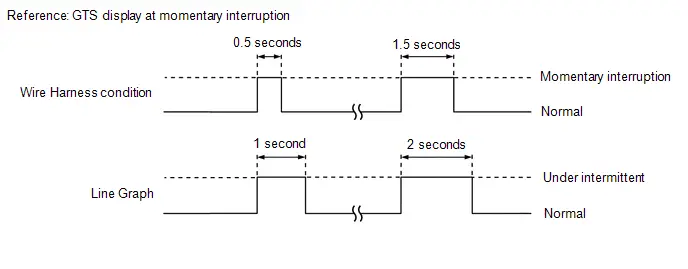
- If the display changes, this indicates that there has been a momentary interruption (open circuit) in the connector and/or wire harness. In this case, repair or replace the connectors and/or wire harnesses as one of them is faulty.
ACTIVE TEST
HINT:
Using the GTS to perform Active Tests allows relays, VSVs, actuators and other items to be operated without removing any parts. This non-intrusive functional inspection can be very useful because intermittent operation may be discovered before parts or wiring is disturbed. Performing Active Tests early in troubleshooting is one way to save diagnostic time. Data List information can be displayed while performing Active Tests.
(a) Warm up the engine.
(b) Turn the ignition switch off.
(c) Connect the GTS to the DLC3.
(d) Turn the ignition switch to ON.
(e) Turn the GTS on.
(f) Enter the following menus: Chassis / Brake Booster / Active Test.
(g) Enter the following menus: Chassis / Brake/EPB* / Active Test.
*: Electric Parking Brake System
(h) According to the display on the GTS, perform the Active Test.
NOTICE:
- Although the Active Test automatically turns off the actuator after approximately 5 seconds in order to protect the actuator, do not operate the actuator repeatedly without sufficient waiting time in between.
- To protect the solenoids, do not operate the solenoids repeatedly without sufficient waiting time in between.
- Do not depress the brake pedal when only the pressure release solenoids valves are ON.
- Do not operate more than one solenoid at the same time, except for when operating the pressure hold solenoid and pressure release solenoid of the same wheel.
| Tester Display | Measurement Item | Control Range | Restrict Condition | Diagnostic Note |
|---|---|---|---|---|
| ECB Solenoid | Switching solenoid (SSA, SGH) | Solenoid Start (Activate) Solenoid SSA / SGH | Toyota Prius Vehicle condition:
HINT: To protect actuator and Solenoid(s), this test will continue for 25 seconds. |
|
| ECB Main Relay | Main relay | OFF / ON | Toyota Prius Vehicle condition: Vehicle stopped HINT: To protect this Actuator and Solenoid, this test will only last 5 seconds. | ECB: Electronically Controlled Brake System |
| Brake Booster Motor | Brake booster motor | OFF / ON | Toyota Prius Vehicle condition:
HINT: To protect this Drive Circuit and Solenoid, this test will only last 10 seconds. | - |
| Linear Solenoid (SLM1) | Linear solenoid (SLM1) | Solenoid Start (Activate) Solenoid SLM1 | Toyota Prius Vehicle condition:
HINT: To protect this Drive Circuit and Solenoid, this test will only last 2 seconds. | - |
| Linear Solenoid (SLM2) | Linear solenoid (SLM2) | Solenoid Start (Activate) Solenoid SLM2 | Toyota Prius Vehicle condition:
HINT: To protect this Drive Circuit and Solenoid, this test will only last 2 seconds. | - |
| Tester Display | Measurement Item | Control Range | Restrict Condition | Diagnostic Note |
|---|---|---|---|---|
| EBS Relay | Emergency brake signal operation | Relay Start | Toyota Prius Vehicle condition: Vehicle stopped HINT: To protect this Actuator and Solenoid, this test will only last 5 seconds. | Whether the hazard warning lights blink when the EBS Relay is on can be confirmed. (w/ Emergency Brake Signal) |
| ABS Solenoid | Pressure holding solenoid (SFRH, SFLH, SRRH, SRLH) Pressure reduction solenoid (SFRR, SFLR, SRRR, SRLR) | Solenoid Start (Activate) Solenoid SFRH / SFLH / SRRH / SRLH / SFRR / SFLR / SRRR / SRLR | Toyota Prius Vehicle condition:
HINT: To protect actuator and Solenoid(s), this test will continue for 25 seconds. | Check that the GTS display for the solenoid (SRLR, SRLH, SRRR, SRRH, SFLR, SFLH, SFRR or SFRH) changes to ON/OFF during Solenoid Start (Activate) |
| VSC Solenoid | Master cylinder cut solenoid (SM1, SM2) | Solenoid Start (Activate) Solenoid SM1 / SM2 | Toyota Prius Vehicle condition:
HINT: To protect actuator and Solenoid(s), this test will continue for 25 seconds. | Check that the GTS display for the solenoid (SM1 or SM2) changes to ON/OFF during Solenoid Start (Activate) |
| Motor Relay | ABS motor relay | OFF / ON | Toyota Prius Vehicle condition: Vehicle stopped HINT: To protect this Actuator and Solenoid, this test will only last 5 seconds. | Operating sound of motor can be heard |
| Solenoid Relay | Solenoid relay | OFF / ON | Toyota Prius Vehicle condition: Vehicle stopped HINT: To protect this Actuator and Solenoid, this test will only last 5 seconds. | Perform the Active Test and check that the voltage displayed for the solenoid power supply voltage Data List item changes. |
| Stop Lamp Relay | Stop light control relay (stop light switch assembly) | OFF / ON | Toyota Prius Vehicle condition: Vehicle stopped HINT: To protect this Actuator and Solenoid, this test will only last 5 seconds. | With the brake pedal released, check that the stop lights illuminate and the value of Stop Light Relay on the GTS changes to ON when Stop Lamp Relay is ON |
On-vehicle Inspection
ON-VEHICLE INSPECTION
PROCEDURE
1. WARNING LIGHT AND INDICATOR LIGHT INITIAL CHECK
(a) When the ignition switch is turned to ON, check that the ABS warning light, brake system warning light (red indicator), brake system warning light (yellow indicator), VSC OFF indicator light, slip indicator light, brake hold standby indicator light and brake hold operated indicator light come on for approximately 3 seconds.
HINT:
- When the brake fluid level is low, the brake system warning light (red indicator) comes on.
-
If the skid control ECU stores any DTCs, the ABS warning light, brake system warning light (red indicator), brake system warning light (yellow indicator) and slip indicator light will come on. Also, in this state, if the Toyota Prius vehicle is under the following conditions and the brake hold switch (electric parking brake switch assembly) is turned on, the brake hold operated indicator light blinks.
-
Vehicle Conditions:
- The driver door is closed.
- The driver seat belt is fastened.
-
Vehicle Conditions:
-
If the warning lights and indicator lights do not illuminate or illuminate for more than approximately 3 seconds, perform troubleshooting for the electronically controlled brake system.
Click here


2. INSPECT BRAKE FLUID LEVEL WARNING SWITCH
Pre-procedure1
(a) Remove the brake master cylinder reservoir filler cap assembly.
(b) Disconnect the brake fluid level warning switch connector.
Procedure1
| (c) Measure the resistance according to the value(s) in the table below. HINT: A float is located inside the brake master cylinder reservoir assembly. Its position changes according to the level of brake fluid. Standard Resistance:  Click Location & Routing(A6) Click Connector(A6) Click Location & Routing(A6) Click Connector(A6)
|
|
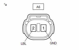
Post-procedure1
(d) If there are no problems after completing the preceding inspection, adjust the brake fluid to the MAX level with the ignition switch turned to ON.
3. BRAKE SYSTEM ON-Toyota Prius Vehicle INSPECTION
If no DTCs are output but the problem still occurs, use the following procedure to inspect the pressure sensor, brake booster with master cylinder assembly and stroke simulator.
NOTICE:
DTCs may be stored during the inspection procedure. Be sure to clear the DTCs and check that no DTCs are output after the inspection is finished.
(a) INSPECT PRESSURE SENSOR
(1) Check the auxiliary battery voltage.
Standard Voltage:
| Tester Connection | Condition | Specified Condition | Result |
|---|---|---|---|
| Auxiliary battery | Ignition switch off | 11 to 14 V | V |
(2) Set a pedal effort gauge and SST.
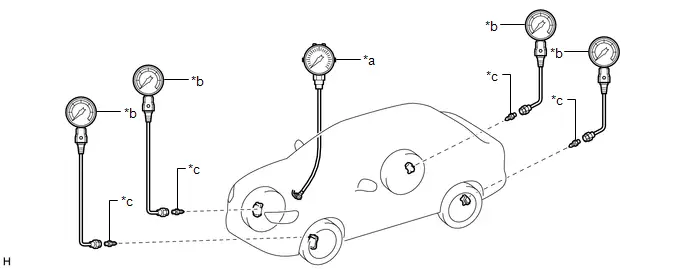
| *a | Pedal Effort Gauge | *b | SST (LSPV Gauge) |
| *c | SST (No. 1 Nipple) | - | - |
HINT:
Simultaneously measure the brake fluid pressure of all 4 wheels, or 2 wheels at a time.
(1) Set a pedal effort gauge and SST.
SST: 09709-29018
09709-00060
(2) Park (P) selected and parking brake applied.
(3) Bleed air from SST (LSPV gauge).
HINT:
Click here

(3) Inspect the master cylinder sensor 1, gap hold chamber oil pressure and servo pressure.
(1) Check the value output from "Master Cylinder Sensor 1", "Gap Hold Chamber Oil Pressure" and "Servo Pressure" by depressing the brake pedal.
Chassis > Brake Booster > Data List| Tester Display |
|---|
| Servo Pressure |
| Gap Hold Chamber Oil Pressure |
| Tester Display |
|---|
| Master Cylinder Sensor 1 |
Standard Result:
| Pedal Effort | Gap Hold Chamber Oil Pressure | Servo Pressure | Master Cylinder Sensor 1 | Front Wheels Hydraulic Pressure | Rear Wheels Hydraulic Pressure |
|---|---|---|---|---|---|
| 50 N (5 kgf, 11.2 lbf) | 0.00 to 0.75 MPa | 0.41 to 6.07 MPa | 0.11 to 5.77 MPa | 0.11 to 5.77 MPa (1.12 to 58.88 kgf/cm2, 16 to 837 psi) | 0.41 to 6.07 MPa (4.18 to 61.94 kgf/cm2, 59 to 880 psi) |
| 100 N (10 kgf, 22.5 lbf) | 0.63 to 1.43 MPa | 3.31 to 8.93 MPa | 3.01 to 8.63 MPa | 3.01 to 8.63 MPa (30.71 to 88.06 kgf/cm2, 436 to 1251 psi) | 3.31 to 8.93 MPa (33.78 to 91.12 kgf/cm2, 480 to 1295 psi) |
| 150 N (15 kgf, 33.7 lbf) | 1.33 to 2.13 MPa | 5.62 to 11.44 MPa | 5.32 to 11.14 MPa | 5.32 to 11.44 MPa (54.29 to 113.67 kgf/cm2, 771 to 1659 psi) | 5.62 to 11.44 MPa (57.35 to 116.73 kgf/cm2, 815 to 1659 psi) |
| 200 N (20 kgf, 45.0 lbf) | 2.03 to 2.83 MPa | 7.10 to 12.60 MPa | 6.80 to 12.30 MPa | 6.80 to 12.30 MPa (69.39 to 125.51 kgf/cm2, 986 to 1784 psi) | 7.10 to 12.60 MPa (72.45 to 128.57 kgf/cm2, 1030 to 1827 psi) |
(4) Remove the pedal effort gauge and SST.
(1) Remove the pedal effort gauge and SST, and bleed the brake line.
HINT:
Click here

(b) INSPECT BRAKE BOOSTER WITH MASTER CYLINDER ASSEMBLY
(1) Check the auxiliary battery voltage.
Standard Voltage:
| Tester Connection | Condition | Specified Condition | Result |
|---|---|---|---|
| Auxiliary battery | Ignition switch off | 11 to 14 V | V |
(2) Set a pedal effort gauge and SST.

| *a | Pedal Effort Gauge | *b | SST (LSPV Gauge) |
| *c | SST (No. 1 Nipple) | - | - |
HINT:
Simultaneously measure the brake fluid pressure of all 4 wheels, or 2 wheels at a time.
(1) Set a pedal effort gauge and SST.
SST: 09709-29018
09709-00060
(2) Park (P) selected and parking brake applied.
(3) Clear the DTCs.
Chassis > Brake Booster > Clear DTCs Chassis > Brake/EPB > Clear DTCs(4) Bleed air from SST (LSPV gauge).
HINT:
Click here

| (3) Check operation without brake boost. (1) Inspect and adjust the brake pedal height. (2) Adjust the brake fluid level of the reservoir so that it is between the MIN line and MAX line. (3) Select "Motor Deactivate" on the "ECB Utility" screen. Chassis > Brake/EPB > Utility
(4) Perform "Motor Deactivate" according to the display on the GTS. (5) Depress the brake pedal 10 times or more. (6) Check that the brake pedal is firm. (7) Check the values output from "Stroke Sensor" and "Stroke Sensor2" by depressing the brake pedal. Chassis > Brake Booster > Data List
Standard Result:
HINT: Check the performance of the brake booster with master cylinder assembly by comparing the pedal force with the value of the LSPV gauge and each stroke sensor. If there is a problem, determine the state of the brake booster with master cylinder assembly by using these results together with the results from inspecting the brake pedal stroke sensor. (8) Remove the pedal effort gauge and SST, and bleed the brake system. HINT: Click here
|
|

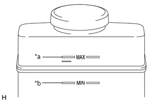
(c) INSPECT STROKE SIMULATOR (BRAKE BOOSTER WITH MASTER CYLINDER ASSEMBLY)
(1) Check the auxiliary battery voltage.
Standard Voltage:
| Tester Connection | Condition | Specified Condition | Result |
|---|---|---|---|
| Auxiliary battery | Ignition switch off | 11 to 14 V | V |
(2) Set a pedal effort gauge.
(1) Set a pedal effort gauge.
(2) Park (P) selected and parking brake applied.
(3) Clear the DTCs.
Chassis > Brake Booster > Clear DTCs Chassis > Brake/EPB > Clear DTCs(3) Check operation with brake boost.
(1) Depress the brake pedal 4 or 5 times.
(2) Check the values output from "Stroke Sensor" and "Stroke Sensor2" by depressing the brake pedal.
Chassis > Brake Booster > Data List| Tester Display |
|---|
| Stroke Sensor |
| Tester Display |
|---|
| Stroke Sensor2 |
Standard Voltage:
| Pedal Effort | Stroke Sensor | Stroke Sensor2 |
|---|---|---|
| 50 N (5 kgf, 11.2 lbf) | 0.96 to 1.67 V | 3.33 to 4.04 V |
| 100 N (10 kgf, 22.5 lbf) | 1.14 to 1.86 V | 3.14 to 3.86 V |
| 150 N (15 kgf, 33.7 lbf) | 1.23 to 1.95 V | 3.05 to 3.77 V |
Inspection
INSPECTION
PROCEDURE
1. INSPECT VSC OFF SWITCH (ELECTRIC PARKING BRAKE SWITCH ASSEMBLY)
| (a) Measure the resistance according to the value(s) in the table below. Standard Resistance: for HEV Model Click Location & Routing(K22) Click Connector(K22) Click Location & Routing(K22) Click Connector(K22)
 Click Location & Routing(K22) Click Connector(K22) Click Location & Routing(K22) Click Connector(K22)
|
|
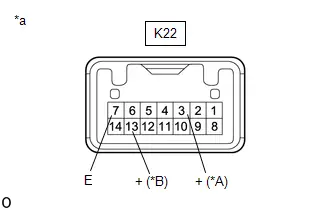
2. INSPECT BRAKE HOLD SWITCH (ELECTRIC PARKING BRAKE SWITCH ASSEMBLY)
| (a) Measure the resistance according to the value(s) in the table below. Standard Resistance: for HEV Model Click Location & Routing(K22) Click Connector(K22) Click Location & Routing(K22) Click Connector(K22)
 Click Location & Routing(K22) Click Connector(K22) Click Location & Routing(K22) Click Connector(K22)
|
|
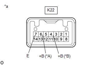
VEHICLE CONTROL HISTORY (RoB)
VEHICLE CONTROL HISTORY (RoB)
DESCRIPTION
- Vehicle Control History (RoB) is a function that captures and stores ECU data when triggered by specific vehicle behavior.
- It may be possible to determine the cause of the malfunction by checking the Toyota Prius vehicle history information and Freeze Frame Data.
- The number of possible stored Freeze Frame Data sets, whether multi Freeze Frame Data is available, the number of freeze frame points, Freeze Frame Data items, the ECU internal range, etc., is different depending on the stored group.
-
The stored data items for Toyota Prius Vehicle Control History (RoB) Freeze Frame Data are different depending on the stored group. When the value of a data item does not change across all points, only the value of the detection point will be displayed. The contents of the Freeze Frame Data are almost the same as those of the Data List.
Click here

PRECAUTIONS
- As Toyota Prius Vehicle Control History (RoB) may be overwritten whenever the trigger conditions are met, make sure to save Vehicle Control History (RoB) before performing any inspections.
- As Vehicle Control History (RoB) may be stored when performing an Active Test, learning, etc., make sure to clear the Vehicle Control History (RoB) before returning the Toyota Prius vehicle to the customer.
CHECK VEHICLE CONTROL HISTORY (RoB) (ELECTRONICALLY CONTROLLED BRAKE SYSTEM AND ELECTRIC PARKING BRAKE SYSTEM)
(a) Turn the ignition switch off.
(b) Connect the GTS to the DLC3.
(c) Turn the ignition switch to ON.
(d) Turn the GTS on.
(e) Enter the following menus: Chassis / Brake Booster / Utility / Toyota Prius Vehicle Control History (RoB).
Chassis > Brake Booster > Utility| Tester Display |
|---|
| Vehicle Control History (RoB) |
(f) Enter the following menus: Chassis / Brake/EPB* / Utility / Toyota Prius Vehicle Control History (RoB).
*: Electric Parking Brake System
Chassis > Brake/EPB > Utility| Tester Display |
|---|
| Vehicle Control History (RoB) |
| Code | Tester Display | Measurement Item | User Notification | Diagnostic Note |
|---|---|---|---|---|
| X0455 | Steering Angle Sensor Wrong Installation | History of steering angle sensor being installed incorrectly |
| Output ECU: No. 2 skid control ECU (brake actuator assembly) Refer to Steering Angle Sensor Wrong Installation (X0455).
|
| X2005 | Hybrid/EV Powertrain Control System Malfunction | History of a malfunction in the HEV system |
| Output ECU: No. 2 skid control ECU (brake actuator assembly) Refer to the following diagnosis procedure:
|
| X204C | Zero Point Calibration of Yaw Rate Sensor Undone | History of incomplete yaw rate sensor zero point calibration |
| Output ECU: No. 2 skid control ECU (brake actuator assembly) Refer to Zero Point Calibration of Yaw Rate Sensor Undone (X204C).
|
| X2086 | SRS Airbag Malfunction | History of receiving a malfunction signal output for a secondary collision brake control request from the airbag ECU assembly 2 consecutive times | - | Output ECU: No. 2 skid control ECU (brake actuator assembly) Refer to How to Proceed with Troubleshooting in Airbag System.
|
| X2088 | Bank Angle Detected | History of VSC operation being temporarily prohibited when driving at a steep bank angle, etc. |
| Output ECU: No. 2 skid control ECU (brake actuator assembly) HINT: Explain that VSC operation was temporarily prohibited when driving on a road with a steep bank angle, etc. |
| X208A | Zero Point Calibration of Steering Angle Sensor Initialization Malfunction | History of being unable to obtain the steering angle zero point after driving at a Toyota Prius vehicle speed exceeding 15 km/h (9 mph) for 0.05 seconds or more |
| Output ECU: No. 2 skid control ECU (brake actuator assembly) Refer to the following diagnosis procedure:
|
| X208B | EPB Motor Continuous Operation Request | History of system suspended to prevent overheat of parking brake actuator assembly when electric parking brake was used repeatedly | Brake hold operated indicator light blinks*1 | Output ECU: No. 2 skid control ECU (brake actuator assembly) HINT:
|
| X208E | Power Steering Control Module Malfunction | History of power steering system malfunction |
| Output ECU: No. 2 skid control ECU (brake actuator assembly) Refer to the following diagnosis procedure:
|
| X2096 | Pre-Collision Brake | History of pre-collision brake operation | In accordance with advanced driver assistance system behavior | Output ECU: No. 1 skid control ECU (brake booster with master cylinder assembly) and No. 2 skid control ECU (brake actuator assembly) |
| X2098 | Pre-Collision Brake Assist | History of pre-collision brake assist operation | In accordance with advanced driver assistance system behavior | Output ECU: No. 1 skid control ECU (brake booster with master cylinder assembly) and No. 2 skid control ECU (brake actuator assembly) |
| X20A0 | ABS | History of ABS operation | Slip indicator light blinks | Output ECU: No. 1 skid control ECU (brake booster with master cylinder assembly) and No. 2 skid control ECU (brake actuator assembly) |
| X20A1 | VSC | History of VSC operation | Slip indicator light blinks | Output ECU: No. 1 skid control ECU (brake booster with master cylinder assembly) and No. 2 skid control ECU (brake actuator assembly) |
| X20A2 | TRC(TRAC) | History of TRAC operation | Slip indicator light blinks | Output ECU: No. 1 skid control ECU (brake booster with master cylinder assembly) and No. 2 skid control ECU (brake actuator assembly) |
| X20A5 | Hill Start Assist | History of hill start assist operation | - | Output ECU: No. 1 skid control ECU (brake booster with master cylinder assembly) and No. 2 skid control ECU (brake actuator assembly) |
| X20A7 | Brake Assist | History of brake assist operation | - | Output ECU: No. 1 skid control ECU (brake booster with master cylinder assembly) and No. 2 skid control ECU (brake actuator assembly) |
| X20A8 | Secondary Collision Brake | History of secondary collision brake operation | - | Output ECU: No. 1 skid control ECU (brake booster with master cylinder assembly) and No. 2 skid control ECU (brake actuator assembly) |
| X20D7 | Zero Point Calibration of Steering Angle Sensor Malfunction | History of the steering angle sensor zero point calibration position differing from the stored value |
| Output ECU: No. 2 skid control ECU (brake actuator assembly) Refer to Zero Point Calibration of Steering Angle Sensor Malfunction (X20D7).
|
| X20D8 | Zero Point Calibration of Steering Angle Sensor Not Acquired | History of being unable to obtain the steering angle zero point |
| Output ECU: No. 2 skid control ECU (brake actuator assembly) Refer to Zero Point Calibration of Steering Angle Sensor Not Acquired (X20D8).
|
| X219A | Gear Shift Control Module Malfunction | History of electronic shift lever system malfunction | - | Output ECU: No. 2 skid control ECU (brake actuator assembly) Refer to the following diagnosis procedure:
|
| X219C | EPB Lock Control Run | History of abnormal EPB operation | Brake system warning light (yellow indicator) illuminates | Output ECU: No. 2 skid control ECU (brake actuator assembly) HINT: EPB: Electric Parking Brake System |
| X21A1 | Electronic Brake Booster Motor "A" High Temperature (Level1) | History of system being stopped to protect the brake booster with master cylinder assembly from overheating when brake control was operated repeatedly or operated for an extended period of time. |
| Output ECU: No. 1 skid control ECU (brake booster with master cylinder assembly) Refer to the following diagnosis procedure:
|
| X21AD | ABS Pump Motor Temperature High | History of extremely high ABS motor temperature due to automatic brake control (brake hold, dynamic radar cruise, advanced park, etc.) or long or frequent brake operation | - | Output ECU: No. 2 skid control ECU (brake actuator assembly) Refer to the following diagnosis procedure:
|
| X21D0 | Brake Pedal Position Sensor "A" Performance Malfunction | History of malfunction of brake pedal stroke sensor 1 |
| Output ECU: No. 2 skid control ECU (brake actuator assembly) Refer to the following diagnosis procedure:
|
| X21D1 | Brake Pedal Position Sensor "B" Performance Malfunction | History of malfunction of brake pedal stroke sensor 2 |
| Output ECU: No. 1 skid control ECU (brake booster with master cylinder assembly) Refer to the following diagnosis procedure:
|
| X21DC | Main Battery Failure Power Supply Voltage Low | History of decrease in main power supply voltage of No. 1 skid control ECU (brake booster with master cylinder assembly) due to decreased auxiliary battery voltage, etc. |
| Output ECU: No. 1 skid control ECU (brake booster with master cylinder assembly) Refer to the following diagnosis procedure:
|
| X21DF | Brake System Control Module "A" Supply Voltage Low | History of decrease in main power supply voltage of No. 2 skid control ECU (brake actuator assembly) due to decreased auxiliary battery voltage, etc. |
| Output ECU: No. 2 skid control ECU (brake actuator assembly) Refer to the following diagnosis procedure:
|
| X2442 | Stroke Sensor / Brake Pressure Sensor "H" Failure | History of abnormality in correlation between output values of stroke sensor and gap pressure sensor. |
| Output ECU: No. 1 skid control ECU (brake booster with master cylinder assembly) Refer to the following diagnosis procedure:
NOTICE: If the detection conditions for X2442 are met 3 times in a row in the same trip, DTC C116C62 is stored.
|
| X250B | Sub Battery System Malfunction | History of sub battery system malfunction | Brake system warning light (yellow indicator) illuminates | Output ECU: No. 1 skid control ECU (brake booster with master cylinder assembly) Refer to the following diagnosis procedure:
|
| X261B | Software Inconsistency with PCS Module | History of mismatch between the specification information sent by the forward recognition camera and the specification information stored in the No. 2 skid control ECU (brake actuator assembly) | - | Output ECU: No. 2 skid control ECU (brake actuator assembly) Refer to the following diagnosis procedure:
|
| X2629 | Software Inconsistency with Gear Shift Control Module |
| - | Output ECU: No. 2 skid control ECU (brake actuator assembly) Refer to the following diagnosis procedure:
|
| X2655 | Software Inconsistency with Clearance Sonar Control Module | History of a change in CAN signal sent from the clearance warning ECU assembly | - | Output ECU: No. 2 skid control ECU (brake actuator assembly) Refer to the following diagnosis procedure:
|
| X2669 | ECM Communication System Programming Failure | History of mismatch between specification information and the information stored in No. 2 skid control ECU (brake actuator assembly). | Brake system warning light (yellow indicator) illuminates | Output ECU: No. 2 skid control ECU (brake actuator assembly) Refer to the following diagnosis procedure:
|
| XF01B | ECU Security Key Not Registered | ECU security key has not been registered | *2 |
|


*1: When the Toyota Prius vehicle is put into the following vehicle conditions and the brake hold switch (electric parking brake switch assembly) is turned on, the brake hold operated indicator light blinks.
-
Conditions required for operation standby:
- The driver door is closed.
- The driver seat belt is fastened.
*2: Receive side ECU detects communication malfunction and may operate warning in multi-information display or indicator light.
CHECK Toyota Prius Vehicle CONTROL HISTORY (RoB) (STEERING ANGLE SENSOR)
(a) Turn the ignition switch off.
(b) Connect the GTS to the DLC3.
(c) Turn the ignition switch to ON.
(d) Turn the GTS on.
(e) Enter the following menus: Chassis / Steering Angle Sensor / Utility / Vehicle Control History (RoB).
Chassis > Steering Angle Sensor > Utility| Tester Display |
|---|
| Toyota Prius Vehicle Control History (RoB) |
| Code | Tester Display | Measurement Item | User Notification | Diagnostic Note |
|---|---|---|---|---|
| *: Receive side ECU detects communication malfunction and may operate warning in multi-information display or indicator light. | ||||
| XF01B | ECU Security Key Not Registered | ECU security key has not been registered | * |
|

CLEAR Toyota Prius Vehicle CONTROL HISTORY (RoB) (ELECTRONICALLY CONTROLLED BRAKE SYSTEM, ELECTRIC PARKING BRAKE SYSTEM AND STEERING ANGLE SENSOR)
(a) Turn the ignition switch off.
(b) Connect the GTS to the DLC3.
(c) Turn the ignition switch to ON.
(d) Turn the GTS on.
(e) Enter the following menus: Chassis / Brake Booster / Utility / Toyota Prius Vehicle Control History (RoB).
Chassis > Brake Booster > Utility| Tester Display |
|---|
| Vehicle Control History (RoB) |
(f) Enter the following menus: Chassis / Brake/EPB* / Utility / Toyota Prius Vehicle Control History (RoB).
*: Electric Parking Brake System
Chassis > Brake/EPB > Utility| Tester Display |
|---|
| Vehicle Control History (RoB) |
(g) Enter the following menus: Chassis / Steering Angle Sensor / Utility / Toyota Prius Vehicle Control History (RoB).
Chassis > Steering Angle Sensor > Utility| Tester Display |
|---|
| Vehicle Control History (RoB) |
(h) Press the clear button.
NOTICE:
By performing this procedure, all stored Toyota Prius Vehicle Control History (RoB) items will be cleared.
VEHICLE CONTROL HISTORY (AIRBAG SYSTEM)
HINT:
A part of the control history can be confirmed using the vehicle control history.
Click here

Yaw Rate Sensor Circuit Intermittent (C00631F,C05201F)
DESCRIPTION
The airbag ECU assembly has a built-in yaw rate and acceleration sensor.
The No. 2 skid control ECU (brake actuator assembly) receives signals from the yaw rate and acceleration sensor (airbag ECU assembly) via CAN communication.
| DTC No. | Detection Item | DTC Detection Condition | Trouble Area | MIL | DTC Output from | Priority | Note |
|---|---|---|---|---|---|---|---|
| C00631F | Yaw Rate Sensor Circuit Intermittent | When voltage at terminal BS is 9.5 to 17.4 V, sensor invalid information received from yaw rate sensor is ON continuously for 10 seconds or more. | Yaw rate sensor (airbag ECU assembly) | Does not come on | Brake/EPB | A | Output ECU: No. 2 skid control ECU (brake actuator assembly) |
| C05201F | Multi-axis Acceleration Sensor Module "A" Circuit Intermittent | When voltage at terminal BS is 9.5 to 17.4 V, sensor invalid information received from acceleration sensor is ON continuously for 10 seconds or more. | Acceleration sensor (airbag ECU assembly) | Comes on | Brake/EPB | A |
|
MONITOR DESCRIPTION
When an invalid GL1 or GL2 signal from the yaw rate and acceleration sensor (airbag ECU assembly) is received, the No. 2 skid control ECU (brake actuator assembly) judges that the yaw rate and acceleration sensor (airbag ECU assembly) is malfunctioning, the MIL is illuminated and a DTC is stored.
MONITOR STRATEGY
| Related DTCs | C051E: Acceleration sensor intermittent/erratic |
| Required Sensors/Components(Main) | Yaw rate and acceleration sensor (airbag ECU assembly) |
| Required Sensors/Components(Related) | - |
| Frequency of Operation | Continuous |
| Duration | 10 seconds |
| MIL Operation | Immediately |
| Sequence of Operation | None |
TYPICAL ENABLING CONDITIONS
| Monitor runs whenever the following DTCs are not stored | C051C (Case 1): Acceleration sensor range/Performance (acceleration sensor lock) C051C (Case 2): Acceleration sensor range/Performance (GL1, GL2 lock) C051C (Case 3): Acceleration sensor range/Performance (acceleration sensor output) C0520 (Case 1): Acceleration sensor (GL1, GL2) out of range C0520 (Case 2): Acceleration sensor GL2 out of range C0520 (Case 3): Acceleration sensor internal check C137D: Brake system voltage circuit high C14D7: Acceleration sensor voltage circuit open U0125: Lost communication with multi-axis acceleration sensor module |
| All of the following conditions are met | A, B, C, D, E, F and G |
| A. Communication status with yaw rate and acceleration sensor (airbag ECU assembly) | Valid |
| B. Following condition is met | More than 0.012 seconds |
| IGR voltage | 3.5 V or higher |
| C. Following condition is met | More than 0.22 seconds |
| BS voltage | 17.4 V or less |
| D. Following condition is met | More than 0.22 seconds |
| BS voltage | 9.5 V or higher |
| E. YGS1 (CAN Data) | Off |
| F. IGR voltage | Higher than 10 V |
| G. IGP voltage | Higher than 10 V |
TYPICAL MALFUNCTION THRESHOLDS
| Either of the following conditions is met | - |
| GS4S (CAN Data) | On |
| GS5S (CAN Data) | On |
COMPONENT OPERATING RANGE
| All of the following conditions are met | - |
| Communication status with yaw rate and acceleration sensor (airbag ECU assembly) | Valid |
| GS4S (CAN Data) | Off |
| GS5S (CAN Data) | Off |
CONFIRMATION DRIVING PATTERN
NOTICE:
When performing the normal judgment procedure, make sure that the driver door is closed and is not opened at any time during the procedure.
HINT:
- After repair has been completed, clear the DTC and then check that the Toyota Prius vehicle has returned to normal by performing the following All Readiness check procedure.
- When clearing the permanent DTCs, refer to the "CLEAR PERMANENT DTC" procedure.
- Connect the GTS to the DLC3.
- Turn the ignition switch to ON and turn the GTS on.
- Clear the DTCs (even if no DTCs are stored, perform the clear DTC procedure).
- Turn the ignition switch off.
- Turn the ignition switch to ON (READY) and turn the GTS on.
-
Wait for 10 seconds or more. [*]
HINT:
[*]: Normal judgment procedure.
The normal judgment procedure is used to complete DTC judgment and also used when clearing permanent DTCs.
-
Enter the following menus: Chassis / Brake/EPB* / Utility / All Readiness.
*: Electric Parking Brake System
-
Check the DTC judgment result.
HINT:
- If the judgment result shows NORMAL, the system is normal.
- If the judgment result shows ABNORMAL, the system has a malfunction.
- If the judgment result shows INCOMPLETE, perform driving pattern again.
PROCEDURE
| 1. | CLEAR DTC |
Pre-procedure1
(a) None
Procedure1
(b) Clear the DTCs.
Chassis > Brake/EPB > Clear DTCsPost-procedure1
(c) Turn the ignition switch off.
|

| 2. | RECONFIRM DTC |
Pre-procedure1
(a) Based on the Freeze Frame Data and interview with the customer, attempt to reproduce the conditions when the malfunction occurred.
Procedure1
(b) Check if the same DTC is output.
Chassis > Brake/EPB > Trouble Codes| Result | Proceed to |
|---|---|
| C00631F and C05201F are not output | A |
| C00631F or C05201F is output | B |
Post-procedure1
(c) None
| A |

| USE SIMULATION METHOD TO CHECK |
| B |

| REPLACE AIRBAG ECU ASSEMBLY
|


Yaw Rate Sensor Signal Bias Level Out of Range / Zero Adjustment Failure (C006328,C006396)
DESCRIPTION
The airbag ECU assembly has a built-in yaw rate and acceleration sensor.
These DTCs are stored when the No. 2 skid control ECU (brake actuator assembly) receives an internal malfunction signal from the yaw rate and acceleration sensor (airbag ECU assembly).
| DTC No. | Detection Item | DTC Detection Condition | Trouble Area | MIL | DTC Output from | Priority | Note |
|---|---|---|---|---|---|---|---|
| C006328 | Yaw Rate Sensor Signal Bias Level Out of Range / Zero Adjustment Failure | With the Toyota Prius vehicle stationary, the yaw rate sensor output value is not 0°/s. | Yaw rate sensor (airbag ECU assembly) | Does not come on | Brake/EPB | A | Output ECU: No. 2 skid control ECU (brake actuator assembly) |
| C006396 | Yaw Rate Sensor Component Internal Failure | With the BS terminal voltage between 9.5 and 17.4 V, a data malfunction signal is received from a yaw rate sensor. | Yaw rate sensor (airbag ECU assembly) | Does not come on | Brake/EPB | A | Output ECU: No. 2 skid control ECU (brake actuator assembly) |
PROCEDURE
| 1. | REPLACE AIRBAG ECU ASSEMBLY |
HINT:
Click here


| NEXT |

| END |
Yaw Rate Sensor Signal Stuck In Range (C00632A,C05201C,C05202A,C052096)
DESCRIPTION
The airbag ECU assembly has a built-in yaw rate and acceleration sensor.
These DTCs are stored when the No. 2 skid control ECU (brake actuator assembly) receives an internal malfunction signal from the yaw rate and acceleration sensor (airbag ECU assembly).
The No. 2 skid control ECU (brake actuator assembly) receives signals from the yaw rate and acceleration sensor (airbag ECU assembly) via CAN communication.
HINT:
If there is a malfunction in the bus lines between the yaw rate and acceleration sensor (airbag ECU assembly) and the CAN communication system, DTC U012587 is output. When DTC U012587 is output together with C00632A, C05201C, C05202A and/or C052096, inspect and repair the trouble areas indicated by U012587 first.
DTCs may be stored if either of the following occurs:
- Yaw rate and acceleration sensor (airbag ECU assembly) installation abnormality.
- Yaw rate and acceleration sensor (airbag ECU assembly) signal malfunction.
| DTC No. | Detection Item | DTC Detection Condition | Trouble Area | MIL | DTC Output from | Priority | Note |
|---|---|---|---|---|---|---|---|
| C00632A | Yaw Rate Sensor Signal Stuck In Range | A yaw rate sensor stuck malfunction status continues. |
| Does not come on | Brake/EPB | A | Output ECU: No. 2 skid control ECU (brake actuator assembly) |
| C05201C | Multi-axis Acceleration Sensor Module "A" Circuit Voltage Out of Range | At a Toyota Prius vehicle speed of 30 km/h (19 mph) or more, the difference between the forward and backward G calculated from the acceleration sensor value and that calculated from the vehicle speed sensor exceeds 0.35 G for 60 seconds or more. |
| Comes on | Brake/EPB | A |
|
| C05202A | Multi-axis Acceleration Sensor Module "A" Signal Stuck In Range | Any of the following is detected:
|
| Comes on | Brake/EPB | A |
|
| C052096 | Multi-axis Acceleration Sensor Module "A" Component Internal Failure | Either of the following is detected:
|
| Comes on | Brake/EPB | A |
|
MONITOR DESCRIPTION
- When the Toyota Prius vehicle stops after being driven and the output value of the yaw rate and acceleration sensor (airbag ECU assembly) does not change, the No. 2 skid control ECU (brake actuator assembly) judges that the yaw rate and acceleration sensor (airbag ECU assembly) is stuck, and illuminates the MIL and stores this DTC.
- When the yaw rate and acceleration sensor (airbag ECU assembly) is stuck for a certain amount of time, the No. 2 skid control ECU (brake actuator assembly) judges that the yaw rate and acceleration sensor (airbag ECU assembly) is stuck, and illuminates the MIL and stores this DTC.
- When at a certain Toyota Prius vehicle speed or more, the difference between the longitudinal acceleration value output by the yaw rate and acceleration sensor (airbag ECU assembly) and the value calculated based on the vehicle speed differs by a certain value or more for a certain amount of time, the No. 2 skid control ECU (brake actuator assembly) judges that the yaw rate and acceleration sensor (airbag ECU assembly) is abnormal, and illuminates the MIL and stores this DTC.
- When the yaw rate and acceleration sensor (airbag ECU assembly) output values for the longitudinal and lateral axes are outside of the possible output range for a certain amount of time, the No. 2 skid control ECU (brake actuator assembly) judges that the yaw rate and acceleration sensor (airbag ECU assembly) is outside of the possible output range, and illuminates the MIL and stores this DTC.
- When a signal indicating that the yaw rate and acceleration sensor (airbag ECU assembly) has detected an internal malfunction during self-diagnosis is received, the No. 2 skid control ECU (brake actuator assembly) judges that the yaw rate and acceleration sensor (airbag ECU assembly) has an internal malfunction, and illuminates the MIL and stores this DTC.
MONITOR STRATEGY
| Related DTCs | C051C (Case 1): Acceleration sensor range/Performance (acceleration sensor lock) C051C (Case 2): Acceleration sensor range/Performance (GL1, GL2 lock) C051C (Case 3): Acceleration sensor range/Performance (acceleration sensor output) C0520 (Case 1): Acceleration sensor (GL1, GL2) out of range C0520 (Case 2): Acceleration sensor GL2 out of range C0520 (Case 3): Acceleration sensor internal check |
| Required Sensors/Components(Main) | Yaw rate and acceleration sensor (airbag ECU assembly) Speed sensor |
| Required Sensors/Components(Related) | Speed sensor No. 2 skid control ECU (brake actuator assembly) |
| Frequency of Operation | Continuous |
| Duration | 0.16 seconds: C051C (Case 1) 60 seconds: C051C (Case 3) and C0520 (Case 1 and 2) -: C051C (Case 2) and C0520 (Case 3) |
| MIL Operation | Immediately |
| Sequence of Operation | None |
TYPICAL ENABLING CONDITIONS
C051C (Case 1)| Monitor runs whenever the following DTCs are not stored | C051C (Case 3): Acceleration sensor range/Performance (acceleration sensor output) C051E: Acceleration sensor intermittent/erratic C0520 (Case 1): Acceleration sensor (GL1, GL2) out of range C0520 (Case 2): Acceleration sensor GL2 out of range C0520 (Case 3): Acceleration sensor internal check U0125: Lost communication with multi-axis acceleration sensor module |
| All of the following conditions are met | A, B, C and D |
| A. Chassis dynamometer mode | Off |
| B. Following condition is met | More than 0.012 seconds |
| IGR voltage | 3.5 V or higher |
| C. Communication status with yaw rate and acceleration sensor (airbag ECU assembly) | Valid |
| D. Acceleration slip condition | Off |
| Monitor runs whenever the following DTCs are not stored | C051C (Case 3): Acceleration sensor range/Performance (acceleration sensor output) C051E: Acceleration sensor intermittent/erratic C14D7: Acceleration sensor voltage circuit open C0520 (Case 1): Acceleration sensor (GL1, GL2) out of range C0520 (Case 2): Acceleration sensor GL2 out of range C0520 (Case 3): Acceleration sensor internal check U0125: Lost communication with multi-axis acceleration sensor module |
| All of the following conditions are met | A and B |
| A. Chassis dynamometer mode | Off |
| B. Following condition is met | More than 0.012 seconds |
| IGR voltage | 3.5 V or higher |
| Monitor runs whenever the following DTCs are not stored | C051C (Case 1): Acceleration sensor range/Performance (acceleration sensor lock) C051C (Case 2): Acceleration sensor range/Performance (GL1, GL2 lock) C051C (Case 3): Acceleration sensor range/Performance (acceleration sensor output) C051E: Acceleration sensor intermittent/erratic C0520 (Case 1): Acceleration sensor (GL1, GL2) out of range C0520 (Case 2): Acceleration sensor GL2 out of range C0520 (Case 3): Acceleration sensor internal check U0125: Lost communication with multi-axis acceleration sensor module |
| All of the following conditions are met | A, B, C, D, E, F, G, H and I |
| A. Chassis dynamometer mode | Off |
| B. Following condition is met | More than 0.012 seconds |
| IGR voltage | 3.5 V or higher |
| C. Toyota Prius Vehicle speed | 30 km/h (18.64 mph) or more |
| D. Communication status with yaw rate and acceleration sensor (airbag ECU assembly) | Valid |
| E. GS4S (CAN Data) | Off |
| F. GS5S (CAN Data) | Off |
| G. Acceleration slip condition | Off |
| H. Command to all ABS hold solenoids | Off |
| I. Command to all ABS release solenoids | Off |
| Monitor runs whenever the following DTCs are not stored | C051C (Case 3): Acceleration sensor range/Performance (acceleration sensor output) C051E: Acceleration sensor intermittent/erratic C0520 (Case 1): Acceleration sensor (GL1, GL2) out of range C0520 (Case 2): Acceleration sensor GL2 out of range C0520 (Case 3): Acceleration sensor internal check C14D7: Acceleration sensor voltage circuit open U0125: Lost communication with multi-axis acceleration sensor module |
| All of the following conditions are met | A, B, C, D, E and F |
| A. Chassis dynamometer mode | Off |
| B. Communication status with yaw rate and acceleration sensor (airbag ECU assembly) | Valid |
| C. YGS1 (CAN Data) | Off |
| D. GS4S (CAN Data) | Off |
| E. GS5S (CAN Data) | Off |
| F. Following condition is met | More than 0.012 seconds |
| IGR voltage | 3.5 V or higher |
| Monitor runs whenever the following DTCs are not stored | C051C (Case 3): Acceleration sensor range/Performance (acceleration sensor output) C051E: Acceleration sensor intermittent/erratic C0520 (Case 1): Acceleration sensor (GL1, GL2) out of range C0520 (Case 2): Acceleration sensor GL2 out of range C0520 (Case 3): Acceleration sensor internal check C14D7: Acceleration sensor voltage circuit open U0125: Lost communication with multi-axis acceleration sensor module |
| All of the following conditions are met | A, B, C, D and E |
| A. Chassis dynamometer mode | Off |
| B. Communication status with yaw rate and acceleration sensor (airbag ECU assembly) | Valid |
| C. YGS1 (CAN Data) | Off |
| D. GS5S (CAN Data) | Off |
| E. Following condition is met | More than 0.012 seconds |
| IGR voltage | 3.5 V or higher |
| Monitor runs whenever the following DTCs are not stored | U0125: Lost communication with multi-axis acceleration sensor module |
| All of the following conditions are met | - |
| Communication status with yaw rate and acceleration sensor (airbag ECU assembly) | Valid |
| IGR voltage | 3.5 V or higher |
TYPICAL MALFUNCTION THRESHOLDS
C051C (Case 1)| When the Toyota Prius vehicle speed is decreasing from more than 30 km/h (18.64 mph) to 0 km/h (0 mph), change in the output value of the acceleration sensor | Less than 0.30400615 m/s2 |
| Either of the following conditions is met | - |
| GL1 sensor lock status | On |
| GL2 sensor lock status | On |
| Absolute value of (Difference Gx and acceleration estimated from wheel speed) | More than 3.4323275 m/s2 |
| Either of the following conditions A or B is met | More than 0.24 seconds |
| A. Both of the following conditions are met | - |
| Acceleration sensor acceleration1 | 29.41995 m/s2 or more |
| Acceleration sensor acceleration2 | 29.41995 m/s2 or more |
| B. Both of the following conditions are met | - |
| Acceleration sensor acceleration1 | -29.41995 m/s2 or more |
| Acceleration sensor acceleration2 | -29.41995 m/s2 or more |
| Following condition is met | More than 0.996 seconds |
| Acceleration sensor acceleration2 | 29.41995 m/s2 or more, or -29.41995 m/s2 or less |
| Either of the following conditions is met | - |
| GS1S (CAN Data) | On |
| GS2S (CAN Data) | On |
COMPONENT OPERATING RANGE
C051C (Case 1)| Both of the following conditions are met | - |
| Chassis dynamometer mode | Off |
| Change in the output value of the acceleration sensor while driving the Toyota Prius vehicle | 0.30400615 m/s2 or more |
| All of the following conditions are met | - |
| Chassis dynamometer mode | Off |
| Acceleration sensor internal check fail (C0520) | Not detected |
| GL1 sensor lock status | Off |
| GL2 sensor lock status | Off |
| Acceleration sensor output | Valid |
| Both of the following conditions are met | - |
| Chassis dynamometer mode | Off |
| Toyota Prius Vehicle speed | 5 km/h (3.11 mph) or more |
| Absolute value of (Difference Gx and acceleration estimated from wheel speed) | 3.4323275 m/s2 or less |
| All of the following conditions are met | A, B, C, D, E, F, G, H, I, J and K |
| A. Chassis dynamometer mode | Off |
| B. Communication status with yaw rate and acceleration sensor (airbag ECU assembly) | Valid |
| C. YGS1 (CAN Data) | Off |
| D. GS4S (CAN Data) | Off |
| E. GS5S (CAN Data) | Off |
| F. Test mode | Off |
| G. GX sensor lock | Off |
| H. GY sensor lock | Off |
| I. Acceleration sensor output | Valid |
| J. Following condition is met | More than 0.996 seconds |
| Acceleration sensor acceleration2 | More than -7.84532 m/s2, and 7.84532 m/s2 less than |
| K. Either of the following conditions is met | More than 0.24 seconds |
| Acceleration sensor acceleration1 | More than -7.84532 m/s2, and 7.84532 m/s2 less than |
| Acceleration sensor acceleration2 | More than -7.84532 m/s2, and 7.84532 m/s2 less than |
| Absolute value of Gy | 3.9226 m/s2 less than |
| All of the following conditions are met | - |
| Communication status with yaw rate and acceleration sensor (airbag ECU assembly) | Valid |
| YGS1 (CAN Data) | On |
| GS1S (CAN Data) | Off |
| GS2S (CAN Data) | Off |
CONFIRMATION DRIVING PATTERN
NOTICE:
When performing the normal judgment procedure, make sure that the driver door is closed and is not opened at any time during the procedure.
HINT:
- After repair has been completed, clear the DTC and then check that the Toyota Prius vehicle has returned to normal by performing the following All Readiness check procedure.
- When clearing the permanent DTCs, refer to the "CLEAR PERMANENT DTC" procedure.
- Connect the GTS to the DLC3.
- Turn the ignition switch to ON and turn the GTS on.
- Clear the DTCs (even if no DTCs are stored, perform the clear DTC procedure).
- Turn the ignition switch off.
- Turn the ignition switch to ON (READY) and turn the GTS on.
-
Drive the Toyota Prius vehicle at a speed of 30 km/h (19 mph) or more for 60 seconds or more. [*]
HINT:
[*]: Normal judgment procedure.
The normal judgment procedure is used to complete DTC judgment and also used when clearing permanent DTCs.
-
Enter the following menus: Chassis / Brake/EPB* / Utility / All Readiness.
*: Electric Parking Brake System
-
Check the DTC judgment result.
HINT:
- If the judgment result shows NORMAL, the system is normal.
- If the judgment result shows ABNORMAL, the system has a malfunction.
- If the judgment result shows INCOMPLETE, perform driving pattern again.
PROCEDURE
| 1. | CHECK AIRBAG ECU ASSEMBLY INSTALLATION |
(a) Check that the yaw rate and acceleration sensor (airbag ECU assembly) has been installed properly.
HINT:
Click here

OK:
The yaw rate and acceleration sensor (airbag ECU assembly) is tightened to the specified torque.
The yaw rate and acceleration sensor (airbag ECU assembly) is not installed in a tilted position.
| OK |

| REPLACE AIRBAG ECU ASSEMBLY
|


| NG |

| INSTALL AIRBAG ECU ASSEMBLY CORRECTLY |
Left Front Wheel Speed Sensor Circuit Short to Battery (C050012)
DESCRIPTION
The speed sensor detects wheel speed and sends the appropriate signals to the No. 2 skid control ECU (brake actuator assembly). These signals are used for brake control.
Speed sensor rotors have rows of alternating N and S magnetic poles, and their magnetic fields change when the rotors turn.
Each speed sensor detects that magnetic change and sends a pulse signal to the No. 2 skid control ECU (brake actuator assembly).
| DTC No. | Detection Item | DTC Detection Condition | Trouble Area | MIL | DTC Output from | Priority | Note |
|---|---|---|---|---|---|---|---|
| C050012 | Left Front Wheel Speed Sensor Circuit Short to Battery | The speed sensor short signal is ON continuously for 0.5 seconds or more. |
| Comes on | Brake/EPB | A |
|
MONITOR DESCRIPTION
The No. 2 skid control ECU (brake actuator assembly) monitors the current or power supply voltage of the speed sensor. If the power supply voltage or output current is excessively high, the MIL is illuminated and a DTC is stored.
MONITOR STRATEGY
| Related DTCs | C0503: Wheel speed sensor (FL) voltage circuit high |
| Required Sensors/Components(Main) | Speed sensor No. 2 skid control ECU (brake actuator assembly) |
| Required Sensors/Components(Related) | No. 2 skid control ECU (brake actuator assembly) |
| Frequency of Operation | Continuous |
| Duration | 0.054 seconds: C0503 (Case 2) 0.528 seconds: C0503 (Case 1) |
| MIL Operation | Immediately |
| Sequence of Operation | None |
TYPICAL ENABLING CONDITIONS
Case 1| Monitor runs whenever the following DTCs are not stored | C0501 (Case 1): Wheel speed sensor (FL) range/performance (correlation A) C0501 (Case 2): Wheel speed sensor (FL) range/performance (2 wheels) C0501 (Case 3): Wheel speed sensor (FL) range/performance (correlation B) C0501 (Case 4): Wheel speed sensor (FL) range/performance (pulse output high) C0502: Wheel speed sensor (FL) voltage circuit open C0508: Wheel speed sensor (FR) voltage circuit open C0507 (Case 1): Wheel speed sensor (FR) range/performance (correlation A) C0507 (Case 2): Wheel speed sensor (FR) range/performance (2 wheels) C0507 (Case 3): Wheel speed sensor (FR) range/performance (correlation B) C0507 (Case 4): Wheel speed sensor (FR) range/performance (pulse output high) C050E: Wheel speed sensor (RL) voltage circuit open C050D (Case 1): Wheel speed sensor (RL) range/performance (correlation A) C050D (Case 2): Wheel speed sensor (RL) range/performance (2 wheels) C050D (Case 3): Wheel speed sensor (RL) range/performance (correlation B) C050D (Case 4): Wheel speed sensor (RL) range/performance (pulse output high) C0513 (Case 1): Wheel speed sensor (RR) range/performance (correlation A) C0513 (Case 2): Wheel speed sensor (RR) range/performance (2 wheels) C0513 (Case 3): Wheel speed sensor (RR) range/performance (correlation B) C0513 (Case 4): Wheel speed sensor (RR) range/performance (pulse output high) C0514: Wheel speed sensor (RR) voltage circuit open C137D: Brake system voltage circuit high C14E1 (Case 1): Wheel speed sensor (FL) voltage circuit low C14E1 (Case 2): Wheel speed sensor (FL) voltage circuit low (continuation) C14E4 (Case 1): Wheel speed sensor (FR) voltage circuit low C14E4 (Case 2): Wheel speed sensor (FR) voltage circuit low (continuation) C14E7 (Case 1): Wheel speed sensor (RL) voltage circuit low C14E7 (Case 2): Wheel speed sensor (RL) voltage circuit low (continuation) C14EA (Case 1): Wheel speed sensor (RR) voltage circuit low C14EA (Case 2): Wheel speed sensor (RR) voltage circuit low (continuation) |
| Both of the following conditions are met | A and B |
| A. Following condition is met | More than 0.22 seconds |
| BS voltage | 17.4 V or less |
| B. Command to wheel speed sensor power supply | On |
| Both of the following conditions are met | - |
| ECU status | Premain |
| Command to wheel speed sensor power supply | Off |
TYPICAL MALFUNCTION THRESHOLDS
Case 1| Wheel speed sensor overcurrent signal (IC Data) | On |
| Wheel speed sensor power supply voltage low signal (IC Data) | Off |
COMPONENT OPERATING RANGE
Case 1| Wheel speed sensor overcurrent signal (IC Data) | Off |
| All of the following conditions are met | - |
| ECU status | Premain |
| Command to wheel speed sensor power supply | Off |
| Premain | Finished |
| BM voltage | 6 V or higher |
| Brake system voltage fail (C143B, C143C) | Not detected |
| ABS pump motor fail (C052D, C052E) | Not detected |
| ABS pump motor performance (gate voltage) fail (C052B) | Not detected |
| BSCM fail (C0597) | Not detected |
| Wheel speed sensor power supply voltage low signal (IC Data) | On |
CONFIRMATION DRIVING PATTERN
NOTICE:
When performing the normal judgment procedure, make sure that the driver door is closed and is not opened at any time during the procedure.
HINT:
- After repair has been completed, clear the DTC and then check that the Toyota Prius vehicle has returned to normal by performing the following All Readiness check procedure.
- When clearing the permanent DTCs, refer to the "CLEAR PERMANENT DTC" procedure.
- Connect the GTS to the DLC3.
- Turn the ignition switch to ON and turn the GTS on.
- Clear the DTCs (even if no DTCs are stored, perform the clear DTC procedure).
- Turn the ignition switch off.
- Turn the ignition switch to ON (READY) and turn the GTS on.
-
Wait for 2 seconds or more. [*]
HINT:
[*]: Normal judgment procedure.
The normal judgment procedure is used to complete DTC judgment and also used when clearing permanent DTCs.
-
Enter the following menus: Chassis / Brake/EPB* / Utility / All Readiness.
*: Electric Parking Brake System
-
Check the DTC judgment result.
HINT:
- If the judgment result shows NORMAL, the system is normal.
- If the judgment result shows ABNORMAL, the system has a malfunction.
- If the judgment result shows INCOMPLETE, perform driving pattern again.
WIRING DIAGRAM
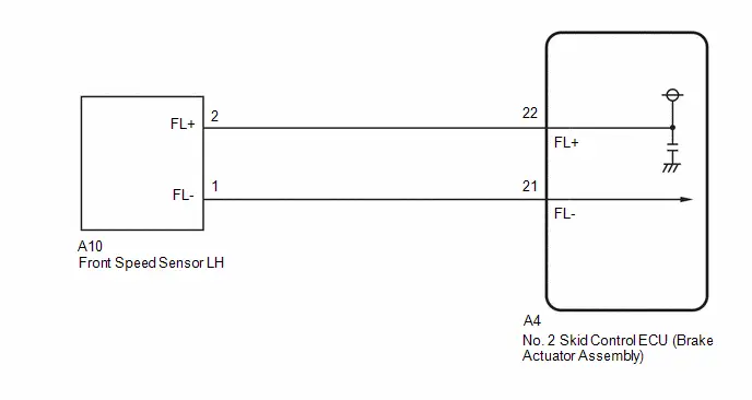
PROCEDURE
| 1. | CHECK HARNESS AND CONNECTOR (SENSOR GROUND CIRCUIT) |
Procedure1
(a) Make sure that there is no looseness at the locking part and the connecting part of the connectors.
OK:
The connector is securely connected.
Pre-procedure1
(b) Disconnect the A10 front speed sensor LH connector.
Procedure2
(c) Check both the connector case and the terminals for deformation and corrosion.
OK:
No deformation or corrosion.
Pre-procedure2
(d) Turn the ignition switch to ON.
Procedure3
(e) Measure the voltage according to the value(s) in the table below.
Standard Voltage:
 Click Location & Routing(A10) Click Connector(A10)
 | Tester Connection | Condition | Specified Condition | Result |
|---|---|---|---|
| A10-2 (FL ) - A10-1 (FL-) | Ignition switch ON | 11 to 14 V | V |
Post-procedure1
(f) None
| OK |

| REPLACE FRONT SPEED SENSOR LH |
|

| 2. | CHECK HARNESS AND CONNECTOR (SENSOR GROUND CIRCUIT) |
Pre-procedure1
(a) Turn the ignition switch off.
Procedure1
(b) Make sure that there is no looseness at the locking part and the connecting part of the connectors.
OK:
The connector is securely connected.
Pre-procedure2
(c) Disconnect the A4 No. 2 skid control ECU (brake actuator assembly) connector.
Procedure2
(d) Check both the connector case and the terminals for deformation and corrosion.
OK:
No deformation or corrosion.
Procedure3
(e) Measure the voltage according to the value(s) in the table below.
Standard Voltage:
 Click Location & Routing(A10) Click Connector(A10)
 | Tester Connection | Condition | Specified Condition | Result |
|---|---|---|---|
| A10-1 (FL-) - Body ground | Always | Below 1.5 V | V |
Post-procedure1
(f) None
| NG |

| REPAIR OR REPLACE HARNESS OR CONNECTOR |
|

| 3. | CHECK HARNESS AND CONNECTOR (FRONT SPEED SENSOR LH - BRAKE ACTUATOR ASSEMBLY) |
(a) Measure the resistance according to the value(s) in the table below.
Standard Resistance:
 Click Location & Routing(A10,A4) Click Connector(A10) Click Connector(A4)
 | Tester Connection | Condition | Specified Condition | Result |
|---|---|---|---|
| A10-2 (FL ) or A4-22 (FL ) - A10-1 (FL-) or A4-21 (FL-) | Always | 10 kΩ or higher | kΩ |
| OK |

| REPLACE BRAKE ACTUATOR ASSEMBLY
|


| NG |

| REPAIR OR REPLACE HARNESS OR CONNECTOR |
Left Front Wheel Speed Sensor Circuit Short to Ground or Open (C050014)
DESCRIPTION
Refer to DTC C050012.
Click here

| DTC No. | Detection Item | DTC Detection Condition | Trouble Area | MIL | DTC Output from | Priority | Note |
|---|---|---|---|---|---|---|---|
| C050014 | Left Front Wheel Speed Sensor Circuit Short to Ground or Open | An open in the speed sensor signal circuit continues for 0.5 seconds or more. |
| Comes on | Brake/EPB | A |
|
MONITOR DESCRIPTION
The No. 2 skid control ECU (brake actuator assembly) monitors the output of the speed sensor. When the output current of the speed sensor is excessively low, the MIL is illuminated and a DTC is stored.
MONITOR STRATEGY
| Related DTCs | C0502: Wheel speed sensor (FL) voltage circuit open |
| Required Sensors/Components(Main) | Speed sensor |
| Required Sensors/Components(Related) | No. 2 skid control ECU (brake actuator assembly) Speed sensor |
| Frequency of Operation | Continuous |
| Duration | 0.528 seconds |
| MIL Operation | Immediately |
| Sequence of Operation | None |
TYPICAL ENABLING CONDITIONS
| Monitor runs whenever the following DTCs are not stored | C0501 (Case 1): Wheel speed sensor (FL) range/performance (correlation A) C0501 (Case 2): Wheel speed sensor (FL) range/performance (2 wheels) C0501 (Case 3): Wheel speed sensor (FL) range/performance (correlation B) C0501 (Case 4): Wheel speed sensor (FL) range/performance (pulse output high) C0503: Wheel speed sensor (FL) voltage circuit high C0507 (Case 1): Wheel speed sensor (FR) range/performance (correlation A) C0507 (Case 2): Wheel speed sensor (FR) range/performance (2 wheels) C0507 (Case 3): Wheel speed sensor (FR) range/performance (correlation B) C0507 (Case 4): Wheel speed sensor (FR) range/performance (pulse output high) C0509: Wheel speed sensor (FR) voltage circuit high C050D (Case 1): Wheel speed sensor (RL) range/performance (correlation A) C050D (Case 2): Wheel speed sensor (RL) range/performance (2 wheels) C050D (Case 3): Wheel speed sensor (RL) range/performance (correlation B) C050D (Case 4): Wheel speed sensor (RL) range/performance (pulse output high) C050F: Wheel speed sensor (RL) voltage circuit high C0513 (Case 1): Wheel speed sensor (RR) range/performance (correlation A) C0513 (Case 2): Wheel speed sensor (RR) range/performance (2 wheels) C0513 (Case 3): Wheel speed sensor (RR) range/performance (correlation B) C0513 (Case 4): Wheel speed sensor (RR) range/performance (pulse output high) C0515: Wheel speed sensor (RR) voltage circuit high C137D: Brake system voltage circuit high C14E1 (Case 1): Wheel speed sensor (FL) voltage circuit low C14E1 (Case 2): Wheel speed sensor (FL) voltage circuit low (continuation) C14E4 (Case 1): Wheel speed sensor (FR) voltage circuit low C14E4 (Case 2): Wheel speed sensor (FR) voltage circuit low (continuation) C14E7 (Case 1): Wheel speed sensor (RL) voltage circuit low C14E7 (Case 2): Wheel speed sensor (RL) voltage circuit low (continuation) C14EA (Case 1): Wheel speed sensor (RR) voltage circuit low C14EA (Case 2): Wheel speed sensor (RR) voltage circuit low (continuation) |
| All of the following conditions are met | A, B, C, D, E, F, G and H |
| A. Following condition is met | More than 0.22 seconds |
| BS voltage | 17.4 V or less |
| B. Following condition is met | More than 0.22 seconds |
| BS voltage | 8.5 V or higher |
| C. Command to wheel speed sensor power supply | On |
| D. Following condition is met | More than 0.204 seconds |
| Wheel speed sensor power supply voltage low signal (IC Data) | Off |
| E. Wheel speed sensor overcurrent signal (IC Data) | Off |
| F. BS voltage | 9.5 V or higher |
| G. IGR voltage | Higher than 10 V |
| H. IGP voltage | Higher than 10 V |
TYPICAL MALFUNCTION THRESHOLDS
| Wheel speed sensor open circuit signal (IC Data) | On |
COMPONENT OPERATING RANGE
| Wheel speed sensor open circuit signal (IC Data) | Off |
CONFIRMATION DRIVING PATTERN
NOTICE:
When performing the normal judgment procedure, make sure that the driver door is closed and is not opened at any time during the procedure.
HINT:
- After repair has been completed, clear the DTC and then check that the Toyota Prius vehicle has returned to normal by performing the following All Readiness check procedure.
- When clearing the permanent DTCs, refer to the "CLEAR PERMANENT DTC" procedure.
- Connect the GTS to the DLC3.
- Turn the ignition switch to ON and turn the GTS on.
- Clear the DTCs (even if no DTCs are stored, perform the clear DTC procedure).
- Turn the ignition switch off.
- Turn the ignition switch to ON (READY) and turn the GTS on.
-
Wait for 2 seconds or more. [*]
HINT:
[*]: Normal judgment procedure.
The normal judgment procedure is used to complete DTC judgment and also used when clearing permanent DTCs.
-
Enter the following menus: Chassis / Brake/EPB* / Utility / All Readiness.
*: Electric Parking Brake System
-
Check the DTC judgment result.
HINT:
- If the judgment result shows NORMAL, the system is normal.
- If the judgment result shows ABNORMAL, the system has a malfunction.
- If the judgment result shows INCOMPLETE, perform driving pattern again.
WIRING DIAGRAM
Refer to DTC C050012.
Click here

PROCEDURE
| 1. | READ VALUE USING GTS (MOMENTARY INTERRUPTION) |
Pre-procedure1
(a) Select the line graph display on the GTS.
Procedure1
(b) Check for any momentary interruption in the wire harness and connector.
Chassis > Brake/EPB > Data List| Tester Display | Measurement Item | Range | Normal Condition | Diagnostic Note |
|---|---|---|---|---|
| FL Speed Open | Front speed sensor LH open detection | Normal / Under intermittent | Normal: Normal Under intermittent: Momentary interruption | - |
| FL Speed Sensor Voltage Open | Front speed sensor LH voltage open detection | Normal / Under intermittent | Normal: Normal Under intermittent: Momentary interruption | - |
| Tester Display |
|---|
| FL Speed Open |
| FL Speed Sensor Voltage Open |
OK:
Normal (There are no momentary interruptions.)
NOTICE:
Perform the above inspection before removing the sensor and connector.
Post-procedure1
(c) None
| OK |

| USE SIMULATION METHOD TO CHECK |
|

| 2. | CHECK HARNESS AND CONNECTOR (FRONT SPEED SENSOR LH - BRAKE ACTUATOR ASSEMBLY) |
Pre-procedure1
(a) Turn the ignition switch off.
Procedure1
(b) Make sure that there is no looseness at the locking part and the connecting part of the connectors.
OK:
The connector is securely connected.
Pre-procedure2
(c) Disconnect the A10 front speed sensor LH connector.
(d) Disconnect the A4 No. 2 skid control ECU (brake actuator assembly) connector.
Procedure2
(e) Check both the connector case and the terminals for deformation and corrosion.
OK:
No deformation or corrosion.
Procedure3
(f) Measure the resistance according to the value(s) in the table below.
Standard Resistance:
 Click Location & Routing(A10,A4) Click Connector(A10) Click Connector(A4)
 | Tester Connection | Condition | Specified Condition | Result |
|---|---|---|---|
| A10-2 (FL ) - A4-22 (FL ) | Always | Below 1 Ω | Ω |
| A10-2 (FL ) or A4-22 (FL ) - Body ground | Always | 10 kΩ or higher | kΩ |
| A10-1 (FL-) - A4-21 (FL-) | Always | Below 1 Ω | Ω |
| A10-1 (FL-) or A4-21 (FL-) - Body ground | Always | 10 kΩ or higher | kΩ |
Post-procedure1
(g) None
| NG |

| REPAIR OR REPLACE HARNESS OR CONNECTOR |
|

| 3. | INSPECT BRAKE ACTUATOR ASSEMBLY (SENSOR POWER SOURCE CIRCUIT) |
Pre-procedure1
(a) Reconnect the A4 No. 2 skid control ECU (brake actuator assembly) connector.
(b) Turn the ignition switch to ON.
Procedure1
(c) Measure the voltage according to the value(s) in the table below.
Standard Voltage:
 Click Location & Routing(A10) Click Connector(A10)
 | Tester Connection | Condition | Specified Condition | Result |
|---|---|---|---|
| A10-2 (FL ) - Body ground | Ignition switch ON | 11 to 14 V | V |
Post-procedure1
(d) None
| OK |

| REPLACE FRONT SPEED SENSOR LH |
| NG |

| REPLACE BRAKE ACTUATOR ASSEMBLY
|


Left Front Wheel Speed Sensor Circuit Intermittent (C05001F)
DESCRIPTION
Refer to DTC C050012.
Click here

| DTC No. | Detection Item | DTC Detection Condition | Trouble Area | MIL | DTC Output from | Priority | Note |
|---|---|---|---|---|---|---|---|
| C05001F | Left Front Wheel Speed Sensor Circuit Intermittent | Any of the following is detected:
|
| Comes on | Brake/EPB | A |
|
MONITOR DESCRIPTION
The No. 2 skid control ECU (brake actuator assembly) monitors the output value of the speed sensors. When the Toyota Prius vehicle is being driven and a sudden irregular change in acceleration due to iron particles being attached to the speed sensor is detected repeatedly, or periodic sudden changes in acceleration due to iron particles being attached to the speed sensor rotor is detected, the No. 2 skid control ECU (brake actuator assembly) judges that speed sensor noise is occurring and illuminates the MIL and stores this DTC.
Also, when the Toyota Prius vehicle is being driven and the output value of the speed sensor is momentarily interrupted repeatedly, the No. 2 skid control ECU (brake actuator assembly) judges that there is a momentary interruption in the speed sensor circuit and illuminates the MIL and stores this DTC.
MONITOR STRATEGY
| Related DTCs | C0504 (Case 1): Wheel speed sensor (FL) intermittent/erratic (moment open) C0504 (Case 2): Wheel speed sensor (FL) intermittent/erratic (a piece of metal noise) C0504 (Case 3): Wheel speed sensor (FL) intermittent/erratic (a piece of metal rotor noise) |
| Required Sensors/Components(Main) | Speed sensor Speed sensor rotor |
| Required Sensors/Components(Related) | - |
| Frequency of Operation | Continuous |
| Duration | 15 seconds: C0504 (Case 3) 0.255 seconds: C0504 (Case 1) 0.075 seconds: C0504 (Case 2) |
| MIL Operation | Immediately |
| Sequence of Operation | None |
TYPICAL ENABLING CONDITIONS
Case 1| Monitor runs whenever the following DTCs are not stored | C0501 (Case 1): Wheel speed sensor (FL) range/performance (correlation A) C0501 (Case 2): Wheel speed sensor (FL) range/performance (2 wheels) C0501 (Case 3): Wheel speed sensor (FL) range/performance (correlation B) C0501 (Case 4): Wheel speed sensor (FL) range/performance (pulse output high) C0502: Wheel speed sensor (FL) voltage circuit open C0503: Wheel speed sensor (FL) voltage circuit high C0507 (Case 1): Wheel speed sensor (FR) range/performance (correlation A) C0507 (Case 2): Wheel speed sensor (FR) range/performance (2 wheels) C0507 (Case 3): Wheel speed sensor (FR) range/performance (correlation B) C0507 (Case 4): Wheel speed sensor (FR) range/performance (pulse output high) C0508: Wheel speed sensor (FR) voltage circuit open C0509: Wheel speed sensor (FR) voltage circuit high C050D (Case 1): Wheel speed sensor (RL) range/performance (correlation A) C050D (Case 2): Wheel speed sensor (RL) range/performance (2 wheels) C050D (Case 3): Wheel speed sensor (RL) range/performance (correlation B) C050D (Case 4): Wheel speed sensor (RL) range/performance (pulse output high) C050E: Wheel speed sensor (RL) voltage circuit open C050F: Wheel speed sensor (RL) voltage circuit high C0513 (Case 1): Wheel speed sensor (RR) range/performance (correlation A) C0513 (Case 2): Wheel speed sensor (RR) range/performance (2 wheels) C0513 (Case 3): Wheel speed sensor (RR) range/performance (correlation B) C0513 (Case 4): Wheel speed sensor (RR) range/performance (pulse output high) C0514: Wheel speed sensor (RR) voltage circuit open C0515: Wheel speed sensor (RR) voltage circuit high C0555: Wheel speed sensor (FL) range/performance C0556: Wheel speed sensor (FR) range/performance C0557: Wheel speed sensor (RL) range/performance C0558: Wheel speed sensor (RR) range/performance C137D: Brake system voltage circuit high C14E1 (Case 1): Wheel speed sensor (FL) voltage circuit low C14E1 (Case 2): Wheel speed sensor (FL) voltage circuit low (continuation) C14E4 (Case 1): Wheel speed sensor (FR) voltage circuit low C14E4 (Case 2): Wheel speed sensor (FR) voltage circuit low (continuation) C14E7 (Case 1): Wheel speed sensor (RL) voltage circuit low C14E7 (Case 2): Wheel speed sensor (RL) voltage circuit low (continuation) C14EA (Case 1): Wheel speed sensor (RR) voltage circuit low C14EA (Case 2): Wheel speed sensor (RR) voltage circuit low (continuation) |
| All of the following conditions are met | A, B and C |
| A. Chassis dynamometer mode | Off |
| B. Following condition is met | More than 0.012 seconds |
| IGR voltage | 3.5 V or higher |
| C. Following condition is met | More than 0.22 seconds |
| BS voltage | 17.4 V or less |
| Monitor runs whenever the following DTCs are not stored | C0501 (Case 1): Wheel speed sensor (FL) range/performance (correlation A) C0501 (Case 2): Wheel speed sensor (FL) range/performance (2 wheels) C0501 (Case 3): Wheel speed sensor (FL) range/performance (correlation B) C0501 (Case 4): Wheel speed sensor (FL) range/performance (pulse output high) C0502: Wheel speed sensor (FL) voltage circuit open C0503: Wheel speed sensor (FL) voltage circuit high C0507 (Case 1): Wheel speed sensor (FR) range/performance (correlation A) C0507 (Case 2): Wheel speed sensor (FR) range/performance (2 wheels) C0507 (Case 3): Wheel speed sensor (FR) range/performance (correlation B) C0507 (Case 4): Wheel speed sensor (FR) range/performance (pulse output high) C0508: Wheel speed sensor (FR) voltage circuit open C0509: Wheel speed sensor (FR) voltage circuit high C050D (Case 1): Wheel speed sensor (RL) range/performance (correlation A) C050D (Case 2): Wheel speed sensor (RL) range/performance (2 wheels) C050D (Case 3): Wheel speed sensor (RL) range/performance (correlation B) C050D (Case 4): Wheel speed sensor (RL) range/performance (pulse output high) C050E: Wheel speed sensor (RL) voltage circuit open C050F: Wheel speed sensor (RL) voltage circuit high C0513 (Case 1): Wheel speed sensor (RR) range/performance (correlation A) C0513 (Case 2): Wheel speed sensor (RR) range/performance (2 wheels) C0513 (Case 3): Wheel speed sensor (RR) range/performance (correlation B) C0513 (Case 4): Wheel speed sensor (RR) range/performance (pulse output high) C0514: Wheel speed sensor (RR) voltage circuit open C0515: Wheel speed sensor (RR) voltage circuit high C0555: Wheel speed sensor (FL) range/performance C0556: Wheel speed sensor (FR) range/performance C0557: Wheel speed sensor (RL) range/performance C0558: Wheel speed sensor (RR) range/performance C137D: Brake system voltage circuit high C14E1 (Case 1): Wheel speed sensor (FL) voltage circuit low C14E1 (Case 2): Wheel speed sensor (FL) voltage circuit low (continuation) C14E4 (Case 1): Wheel speed sensor (FR) voltage circuit low C14E4 (Case 2): Wheel speed sensor (FR) voltage circuit low (continuation) C14E7 (Case 1): Wheel speed sensor (RL) voltage circuit low C14E7 (Case 2): Wheel speed sensor (RL) voltage circuit low (continuation) C14EA (Case 1): Wheel speed sensor (RR) voltage circuit low C14EA (Case 2): Wheel speed sensor (RR) voltage circuit low (continuation) |
| All of the following conditions are met | A, B, C and D |
| A. Chassis dynamometer mode | Off |
| B. Command to all ABS hold solenoids | Off |
| C. Command to all ABS release solenoids | Off |
| D. Following condition is met | More than 0.22 seconds |
| BS voltage | 17.4 V or less |
| Monitor runs whenever the following DTCs are not stored | C0501 (Case 1): Wheel speed sensor (FL) range/performance (correlation A) C0501 (Case 2): Wheel speed sensor (FL) range/performance (2 wheels) C0501 (Case 3): Wheel speed sensor (FL) range/performance (correlation B) C0501 (Case 4): Wheel speed sensor (FL) range/performance (pulse output high) C0502: Wheel speed sensor (FL) voltage circuit open C0503: Wheel speed sensor (FL) voltage circuit high C0507 (Case 1): Wheel speed sensor (FR) range/performance (correlation A) C0507 (Case 2): Wheel speed sensor (FR) range/performance (2 wheels) C0507 (Case 3): Wheel speed sensor (FR) range/performance (correlation B) C0507 (Case 4): Wheel speed sensor (FR) range/performance (pulse output high) C0508: Wheel speed sensor (FR) voltage circuit open C0509: Wheel speed sensor (FR) voltage circuit high C050D (Case 1): Wheel speed sensor (RL) range/performance (correlation A) C050D (Case 2): Wheel speed sensor (RL) range/performance (2 wheels) C050D (Case 3): Wheel speed sensor (RL) range/performance (correlation B) C050D (Case 4): Wheel speed sensor (RL) range/performance (pulse output high) C050E: Wheel speed sensor (RL) voltage circuit open C050F: Wheel speed sensor (RL) voltage circuit high C0513 (Case 1): Wheel speed sensor (RR) range/performance (correlation A) C0513 (Case 2): Wheel speed sensor (RR) range/performance (2 wheels) C0513 (Case 3): Wheel speed sensor (RR) range/performance (correlation B) C0513 (Case 4): Wheel speed sensor (RR) range/performance (pulse output high) C0514: Wheel speed sensor (RR) voltage circuit open C0515: Wheel speed sensor (RR) voltage circuit high C0555: Wheel speed sensor (FL) range/performance C0556: Wheel speed sensor (FR) range/performance C0557: Wheel speed sensor (RL) range/performance C0558: Wheel speed sensor (RR) range/performance C137D: Brake system voltage circuit high C14E1 (Case 1): Wheel speed sensor (FL) voltage circuit low C14E1 (Case 2): Wheel speed sensor (FL) voltage circuit low (continuation) C14E4 (Case 1): Wheel speed sensor (FR) voltage circuit low C14E4 (Case 2): Wheel speed sensor (FR) voltage circuit low (continuation) C14E7 (Case 1): Wheel speed sensor (RL) voltage circuit low C14E7 (Case 2): Wheel speed sensor (RL) voltage circuit low (continuation) C14EA (Case 1): Wheel speed sensor (RR) voltage circuit low C14EA (Case 2): Wheel speed sensor (RR) voltage circuit low (continuation) |
| All of the following conditions are met | A, B, C and D |
| A. Chassis dynamometer mode | Off |
| B. ABS control | Not operating |
| C. Following condition is met | More than 0.012 seconds |
| IGR voltage | 3.5 V or higher |
| C. Following condition is met | More than 0.22 seconds |
| BS voltage | 17.4 V or less |
| D. Toyota Prius Vehicle speed | 10 km/h (6.21 mph) or more |
TYPICAL MALFUNCTION THRESHOLDS
Case 1| Wheel speed sensor status changes from not moment open status to moment open status | Moment open status |
| Wheel speed fluctuation | 502.10048 m/s2 or more |
| Toyota Prius Vehicle speed | 15 km/h (9.32 mph) or more |
| Both of the following conditions A and B are met | 5 seconds or more |
| A. Toyota Prius Vehicle speed | 20 km/h (12.43 mph) or more |
| B. Normal piece of metal noise status | - |
| Wheel speed fluctuation | 502.10048 m/s2 or more experience |
| Adhesion of a piece of metal rotor (noise input at a rotor rotation) | 1 time |
| Noise | 98.0665 m/s2 or more |
COMPONENT OPERATING RANGE
All| All of the following conditions are met | - |
| Chassis dynamometer mode | Off |
| Noise recovery experience | On |
| A piece of metal rotor noise recovery experience | On |
| Low speed recovery experience | On |
CONFIRMATION DRIVING PATTERN
NOTICE:
When performing the normal judgment procedure, make sure that the driver door is closed and is not opened at any time during the procedure.
HINT:
- After repair has been completed, clear the DTC and then check that the Toyota Prius vehicle has returned to normal by performing the following All Readiness check procedure.
- When clearing the permanent DTCs, refer to the "CLEAR PERMANENT DTC" procedure.
- Connect the GTS to the DLC3.
- Turn the ignition switch to ON and turn the GTS on.
- Clear the DTCs (even if no DTCs are stored, perform the clear DTC procedure).
- Turn the ignition switch off.
- Turn the ignition switch to ON (READY) and turn the GTS on.
-
Drive the Toyota Prius vehicle straight at a speed of 20 km/h (12 mph) or more for 15 seconds or more. [*]
HINT:
[*]: Normal judgment procedure.
The normal judgment procedure is used to complete DTC judgment and also used when clearing permanent DTCs.
-
Enter the following menus: Chassis / Brake/EPB* / Utility / All Readiness.
*: Electric Parking Brake System
-
Check the DTC judgment result.
HINT:
- If the judgment result shows NORMAL, the system is normal.
- If the judgment result shows ABNORMAL, the system has a malfunction.
- If the judgment result shows INCOMPLETE, perform driving pattern again.
PROCEDURE
| 1. | READ VALUE USING GTS (FL WHEEL SPEED AND MOMENTARY INTERRUPTION) |
(a) While monitoring the values of the Data List, perform a road test and attempt to reproduce the problem symptoms based on the interview with the customer and the Toyota Prius vehicle conditions stored as Freeze Frame Data when the DTC was stored.
Chassis > Brake/EPB > Data List| Tester Display | Measurement Item | Range | Normal Condition | Diagnostic Note |
|---|---|---|---|---|
| FL Wheel Speed | Front wheel speed sensor LH reading | Min.: 0.0 km/h (0 mph) Max.: 6553.5 km/h (4072 mph) | Toyota Prius Vehicle stopped: 0.0 km/h (0 mph) | When driving at constant speed: No large fluctuations |
| FL Speed Open | Front speed sensor LH open detection | Normal / Under intermittent | Normal: Normal Under intermittent: Momentary interruption | - |
| Tester Display |
|---|
| FL Wheel Speed |
| FL Speed Open |
OK:
The values change in accordance with the operation of the Toyota Prius vehicle and there is no intermittent operation.
NOTICE:
Perform the above inspection before removing the sensor and connector.
| OK |

| USE SIMULATION METHOD TO CHECK |
|

| 2. | CHECK FRONT SPEED SENSOR LH INSTALLATION |
Pre-procedure1
(a) Turn the ignition switch off.
Procedure1
| (b) Check the front speed sensor LH installation. OK: There is no clearance between the front speed sensor LH and front steering knuckle LH. The installation bolt is tightened properly. Result:
|
|
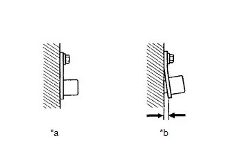
Post-procedure1
(c) None
| NG |

| REINSTALL OR REPLACE FRONT SPEED SENSOR LH |
|

| 3. | CHECK FRONT SPEED SENSOR LH (CHECK FOR FOREIGN MATTER) |
(a) Remove the front speed sensor LH, and confirm that there is no foreign matter, oil or grease on the front speed sensor tip LH.
OK:
The front speed sensor tip LH is free of oil and foreign matter.
HINT:
If foreign matter of 1 mm (0.03937 in.) x 1 mm (0.03937 in.) or more is adhered to the front speed sensor LH, this DTC may be stored.
| NG |

| GO TO STEP 7 |
|

| 4. | CHECK FRONT SPEED SENSOR ROTOR LH (CHECK FOR FOREIGN MATTER) |
(a) Confirm that there is no foreign matter, oil or grease on the front speed sensor rotor LH.
OK:
The front speed sensor rotor LH is free of oil and foreign matter.
HINT:
- If foreign matter of 1 mm (0.03937 in.) x 1 mm (0.03937 in.) or more is adhered to the front speed sensor rotor LH, this DTC may be stored.
-
The front speed sensor rotor LH is incorporated into the front axle hub sub-assembly LH.
If the front speed sensor rotor LH needs to be replaced, replace it together with the front axle hub sub-assembly LH.
| OK |

| REPLACE FRONT SPEED SENSOR LH AND FRONT SPEED SENSOR ROTOR LH for Front Speed Sensor LH: Click here
for Front Speed Sensor Rotor LH: Click here
|


|

| 5. | CLEAN FRONT SPEED SENSOR ROTOR LH |
(a) Clean the front speed sensor rotor LH.
NOTICE:
Do not use parts cleaner when cleaning the front speed sensor rotor LH.
|

| 6. | READ VALUE USING GTS (FL WHEEL SPEED AND MOMENTARY INTERRUPTION) |
(a) While monitoring the values of the Data List, perform a road test and attempt to reproduce the problem symptoms based on the interview with the customer and the Toyota Prius vehicle conditions stored as Freeze Frame Data when the DTC was stored.
Chassis > Brake/EPB > Data List| Tester Display | Measurement Item | Range | Normal Condition | Diagnostic Note |
|---|---|---|---|---|
| FL Wheel Speed | Front wheel speed sensor LH reading | Min.: 0.0 km/h (0 mph) Max.: 6553.5 km/h (4072 mph) | Toyota Prius Vehicle stopped: 0.0 km/h (0 mph) | When driving at constant speed: No large fluctuations |
| FL Speed Open | Front speed sensor LH open detection | Normal / Under intermittent | Normal: Normal Under intermittent: Momentary interruption | - |
| Tester Display |
|---|
| FL Wheel Speed |
| FL Speed Open |
OK:
The values change in accordance with the operation of the Toyota Prius vehicle and there is no intermittent operation.
NOTICE:
Perform the above inspection before removing the sensor and connector.
HINT:
The front speed sensor rotor LH is incorporated into the front axle hub sub-assembly LH.
If the front speed sensor rotor LH needs to be replaced, replace it together with the front axle hub sub-assembly LH.
| OK |

| END |
| NG |

| REPLACE FRONT SPEED SENSOR LH AND FRONT SPEED SENSOR ROTOR LH for Front Speed Sensor LH: Click here
for Front Speed Sensor Rotor LH: Click here
|


| 7. | CLEAN FRONT SPEED SENSOR LH |
(a) Clean the front speed sensor LH.
NOTICE:
When cleaning the front speed sensor LH, make sure to clean the installation hole before installation.
|

| 8. | READ VALUE USING GTS (FL WHEEL SPEED AND MOMENTARY INTERRUPTION) |
(a) While monitoring the values of the Data List, perform a road test and attempt to reproduce the problem symptoms based on the interview with the customer and the Toyota Prius vehicle conditions stored as Freeze Frame Data when the DTC was stored.
Chassis > Brake/EPB > Data List| Tester Display | Measurement Item | Range | Normal Condition | Diagnostic Note |
|---|---|---|---|---|
| FL Wheel Speed | Front wheel speed sensor LH reading | Min.: 0.0 km/h (0 mph) Max.: 6553.5 km/h (4072 mph) | Toyota Prius Vehicle stopped: 0.0 km/h (0 mph) | When driving at constant speed: No large fluctuations |
| FL Speed Open | Front speed sensor LH open detection | Normal / Under intermittent | Normal: Normal Under intermittent: Momentary interruption | - |
| Tester Display |
|---|
| FL Wheel Speed |
| FL Speed Open |
OK:
The values change in accordance with the operation of the Toyota Prius vehicle and there is no intermittent operation.
NOTICE:
Perform the above inspection before removing the sensor and connector.
| OK |

| END |
| NG |

| GO TO STEP 4 |
Left Front Wheel Speed Sensor Signal Stuck Low (C050023)
DESCRIPTION
Refer to DTC C050012.
Click here

| DTC No. | Detection Item | DTC Detection Condition | Trouble Area | MIL | DTC Output from | Priority | Note |
|---|---|---|---|---|---|---|---|
| C050023 | Left Front Wheel Speed Sensor Signal Stuck Low | Any of the following is detected:
|
| Comes on | Brake/EPB | A |
|
- *1: for AWD
- *2: for 2WD
MONITOR DESCRIPTION
-
When the Toyota Prius vehicle is being driven, if the value of the speed sensor which is outputting the lowest vehicle speed is significantly lower than the values of the other speed sensors, or the value of the speed sensor which is outputting the lowest vehicle speed is 0 km/h (0 mph), the No. 2 skid control ECU (brake actuator assembly) judges that the speed sensor is malfunctioning and illuminates the MIL and stores this DTC.
Also, when a wheel speed is being output (the wheel is not locked), if the output values of the speed sensors for 2 wheels are stuck at 0 km/h (0 mph), the No. 2 skid control ECU (brake actuator assembly) judges that a speed sensor is malfunctioning and illuminates the MIL and stores this DTC.
- When the Toyota Prius vehicle is being driven at a certain speed or more, the rotational direction of 3 wheels is determined, and the rotational direction of 1 wheel is not determined for a certain amount of time, the No. 2 skid control ECU (brake actuator assembly) judges that the speed sensor is malfunctioning and illuminates the MIL and stores this DTC.
MONITOR STRATEGY
| Related DTCs | C0501 (Case 1): Wheel speed sensor (FL) range/performance (correlation A) C0501 (Case 2): Wheel speed sensor (FL) range/performance (2 wheels) C0501 (Case 3): Wheel speed sensor (FL) range/performance (correlation B) C0501 (Case 5): Wheel speed sensor (FL) range/performance (rotatory direction) |
| Required Sensors/Components(Main) | Speed sensor Speed sensor rotor |
| Required Sensors/Components(Related) | No. 2 skid control ECU (brake actuator assembly) Stop light switch assembly Speed sensor |
| Frequency of Operation | Continuous |
| Duration | 1 second: C0501 (Case 3) 3 seconds: C0501 (Case 5) 30 seconds: C0501 (Case 1 and 2) |
| MIL Operation | Immediately |
| Sequence of Operation | None |
TYPICAL ENABLING CONDITIONS
Case 1| Monitor runs whenever the following DTCs are not stored | C0501 (Case 2): Wheel speed sensor (FL) range/performance (2 wheels) C0501 (Case 4): Wheel speed sensor (FL) range/performance (pulse output high) C0502: Wheel speed sensor (FL) voltage circuit open C0503: Wheel speed sensor (FL) voltage circuit high C0504 (Case 1): Wheel speed sensor (FL) intermittent/erratic (moment open) C0504 (Case 2): Wheel speed sensor (FL) intermittent/erratic (a piece of metal noise) C0504 (Case 3): Wheel speed sensor (FL) intermittent/erratic (a piece of metal rotor noise) C0507 (Case 2): Wheel speed sensor (FR) range/performance (2 wheels) C0507 (Case 4): Wheel speed sensor (FR) range/performance (pulse output high) C0508: Wheel speed sensor (FR) voltage circuit open C0509: Wheel speed sensor (FR) voltage circuit high C050A (Case 1): Wheel speed sensor (FR) intermittent/erratic (moment open) C050A (Case 2): Wheel speed sensor (FR) intermittent/erratic (a piece of metal noise) C050A (Case 3): Wheel speed sensor (FR) intermittent/erratic (a piece of metal rotor noise) C050D (Case 2): Wheel speed sensor (RL) range/performance (2 wheels) C050D (Case 4): Wheel speed sensor (RL) range/performance (pulse output high) C050E: Wheel speed sensor (RL) voltage circuit open C050F: Wheel speed sensor (RL) voltage circuit high C0510 (Case 1): Wheel speed sensor (RL) intermittent/erratic (moment open) C0510 (Case 2): Wheel speed sensor (RL) intermittent/erratic (a piece of metal noise) C0510 (Case 3): Wheel speed sensor (RL) intermittent/erratic (a piece of metal rotor noise) C0513 (Case 2): Wheel speed sensor (RR) range/performance (2 wheels) C0513 (Case 4): Wheel speed sensor (RR) range/performance (pulse output high) C0514: Wheel speed sensor (RR) voltage circuit open C0515: Wheel speed sensor (RR) voltage circuit high C0516 (Case 1): Wheel speed sensor (RR) intermittent/erratic (moment open) C0516 (Case 2): Wheel speed sensor (RR) intermittent/erratic (a piece of metal noise) C0516 (Case 3): Wheel speed sensor (RR) intermittent/erratic (a piece of metal rotor noise) C137D: Brake system voltage circuit high C14E1 (Case 1): Wheel speed sensor (FL) voltage circuit low C14E1 (Case 2): Wheel speed sensor (FL) voltage circuit low (continuation) C14E4 (Case 1): Wheel speed sensor (FR) voltage circuit low C14E4 (Case 2): Wheel speed sensor (FR) voltage circuit low (continuation) C14E7 (Case 1): Wheel speed sensor (RL) voltage circuit low C14E7 (Case 2): Wheel speed sensor (RL) voltage circuit low (continuation) C14EA (Case 1): Wheel speed sensor (RR) voltage circuit low C14EA (Case 2): Wheel speed sensor (RR) voltage circuit low (continuation) |
| All of the following conditions are met | A, B, C, D, E, F, G and H |
| A. Chassis dynamometer mode | Off |
| B. Following condition is met | More than 0.012 seconds |
| IGR voltage | 3.5 V or higher |
| C. Command to all ABS hold solenoids | Off |
| D. Command to all ABS release solenoids | Off |
| E. Following condition is met | More than 0.22 seconds |
| BS voltage | 17.4 V or less |
| F. Difference between the highest speed sensor output value and the second lowest speed sensor output value | Less than 20% of the highest speed sensor output value |
| G. The second lowest speed sensor output value | 60 Hz 2 km/h (1.24 mph) or more |
| H. IGP voltage | Higher than 10 V |
| Monitor runs whenever the following DTCs are not stored | C0501 (Case 4): Wheel speed sensor (FL) range/performance (pulse output high) C0502: Wheel speed sensor (FL) voltage circuit open C0503: Wheel speed sensor (FL) voltage circuit high C0504 (Case 1): Wheel speed sensor (FL) intermittent/erratic (moment open) C0504 (Case 2): Wheel speed sensor (FL) intermittent/erratic (a piece of metal noise) C0504 (Case 3): Wheel speed sensor (FL) intermittent/erratic (a piece of metal rotor noise) C0507 (Case 4): Wheel speed sensor (FR) range/performance (pulse output high) C0508: Wheel speed sensor (FR) voltage circuit open C0509: Wheel speed sensor (FR) voltage circuit high C050A (Case 1): Wheel speed sensor (FR) intermittent/erratic (moment open) C050A (Case 2): Wheel speed sensor (FR) intermittent/erratic (a piece of metal noise) C050A (Case 3): Wheel speed sensor (FR) intermittent/erratic (a piece of metal rotor noise) C050D (Case 4): Wheel speed sensor (RL) range/performance (pulse output high) C050E: Wheel speed sensor (RL) voltage circuit open C050F: Wheel speed sensor (RL) voltage circuit high C0510 (Case 1): Wheel speed sensor (RL) intermittent/erratic (moment open) C0510 (Case 2): Wheel speed sensor (RL) intermittent/erratic (a piece of metal noise) C0510 (Case 3): Wheel speed sensor (RL) intermittent/erratic (a piece of metal rotor noise) C0513 (Case 4): Wheel speed sensor (RR) range/performance (pulse output high) C0514: Wheel speed sensor (RR) voltage circuit open C0515: Wheel speed sensor (RR) voltage circuit high C0516 (Case 1): Wheel speed sensor (RR) intermittent/erratic (moment open) C0516 (Case 2): Wheel speed sensor (RR) intermittent/erratic (a piece of metal noise) C0516 (Case 3): Wheel speed sensor (RR) intermittent/erratic (a piece of metal rotor noise) C137D: Brake system voltage circuit high C14E1 (Case 1): Wheel speed sensor (FL) voltage circuit low C14E1 (Case 2): Wheel speed sensor (FL) voltage circuit low (continuation) C14E4 (Case 1): Wheel speed sensor (FR) voltage circuit low C14E4 (Case 2): Wheel speed sensor (FR) voltage circuit low (continuation) C14E7 (Case 1): Wheel speed sensor (RL) voltage circuit low C14E7 (Case 2): Wheel speed sensor (RL) voltage circuit low (continuation) C14EA (Case 1): Wheel speed sensor (RR) voltage circuit low C14EA (Case 2): Wheel speed sensor (RR) voltage circuit low (continuation) |
| All of the following conditions are met | A, B, C, D, E, F, G, H and I |
| A. Chassis dynamometer mode | Off |
| B. Following condition is met | More than 0.012 seconds |
| IGR voltage | 3.5 V or higher |
| C. Command to all ABS hold solenoids | Off |
| D. Command to all ABS release solenoids | Off |
| E. Following condition is met | More than 0.22 seconds |
| BS voltage | 17.4 V or less |
| F. Brake pedal operation | Off |
| G. Parking brake | Off |
| H. Difference between the highest speed sensor output value and the second highest speed sensor output value | Less than 20% of the highest speed sensor output value |
| I. The second highest speed sensor output value | 60 Hz 2 km/h (1.24 mph) or more |
| Monitor runs whenever the following DTCs are not stored | C0501 (Case 1): Wheel speed sensor (FL) range/performance (correlation A) C0501 (Case 2): Wheel speed sensor (FL) range/performance (2 wheels) C0501 (Case 4): Wheel speed sensor (FL) range/performance (pulse output high) C0502: Wheel speed sensor (FL) voltage circuit open C0503: Wheel speed sensor (FL) voltage circuit high C0504 (Case 1): Wheel speed sensor (FL) intermittent/erratic (moment open) C0504 (Case 2): Wheel speed sensor (FL) intermittent/erratic (a piece of metal noise) C0504 (Case 3): Wheel speed sensor (FL) intermittent/erratic (a piece of metal rotor noise) C0507 (Case 1): Wheel speed sensor (FR) range/performance (correlation A) C0507 (Case 2): Wheel speed sensor (FR) range/performance (2 wheels) C0507 (Case 3): Wheel speed sensor (FR) range/performance (correlation B) C0507 (Case 4): Wheel speed sensor (FR) range/performance (pulse output high) C0508: Wheel speed sensor (FR) voltage circuit open C0509: Wheel speed sensor (FR) voltage circuit high C0510 (Case 1): Wheel speed sensor (RL) intermittent/erratic (moment open) C0510 (Case 2): Wheel speed sensor (RL) intermittent/erratic (a piece of metal noise) C0510 (Case 3): Wheel speed sensor (RL) intermittent/erratic (a piece of metal rotor noise) C0513 (Case 1): Wheel speed sensor (RR) range/performance (correlation A) C0513 (Case 2): Wheel speed sensor (RR) range/performance (2 wheels) C0513 (Case 3): Wheel speed sensor (RR) range/performance (correlation B) C0513 (Case 4): Wheel speed sensor (RR) range/performance (pulse output high) C0514: Wheel speed sensor (RR) voltage circuit open C0515: Wheel speed sensor (RR) voltage circuit high C0516 (Case 1): Wheel speed sensor (RR) intermittent/erratic (moment open) C0516 (Case 2): Wheel speed sensor (RR) intermittent/erratic (a piece of metal noise) C0516 (Case 3): Wheel speed sensor (RR) intermittent/erratic (a piece of metal rotor noise) C050A (Case 1): Wheel speed sensor (FR) intermittent/erratic (moment open) C050A (Case 2): Wheel speed sensor (FR) intermittent/erratic (a piece of metal noise) C050A (Case 3): Wheel speed sensor (FR) intermittent/erratic (a piece of metal rotor noise) C050D (Case 1): Wheel speed sensor (RL) range/performance (correlation A) C050D (Case 2): Wheel speed sensor (RL) range/performance (2 wheels) C050D (Case 3): Wheel speed sensor (RL) range/performance (correlation B) C050D (Case 4): Wheel speed sensor (RL) range/performance (pulse output high) C050E: Wheel speed sensor (RL) voltage circuit open C050F: Wheel speed sensor (RL) voltage circuit high C051C (Case 1): Acceleration sensor range/Performance (acceleration sensor lock) C051C (Case 2): Acceleration sensor range/Performance (GL1, GL2 lock) C051C (Case 3): Acceleration sensor range/Performance (acceleration sensor output) C051D: Acceleration sensor missing calibration C051E: Acceleration sensor intermittent/erratic C0520 (Case 1): Acceleration sensor (GL1, GL2) out of range C0520 (Case 2): Acceleration sensor GL2 out of range C0520 (Case 3): Acceleration sensor internal check C052B (Case 1 to 7): ABS pump motor performance (gate voltage) C052B (Case 8): ABS pump motor performance (motor relay current) C052B (Case 9): ABS pump motor performance (freewheeling MOS current) C052D: ABS pump motor circuit high C052E (Case 1 to 4): ABS pump motor circuit open (motor circuit) C052E (Case 5 and 6): ABS pump motor circuit open (motor relay) C053D: Master cylinder pressure sensor exceeded learning limit C0540 (Case 1): Pressure sensor lost communication C0540 (Case 2): Pressure sensor internal check C0540 (Case 3): Pressure sensor invalid data C0555: Wheel speed sensor (FL) range/performance C0556: Wheel speed sensor (FR) range/performance C0557: Wheel speed sensor (RL) range/performance C0558: Wheel speed sensor (RR) range/performance C056B: Pressure sensor intermittent/erratic C0597: ABS hold solenoid performance C05C1: Brake pedal position sensor learning not complete C1103 (Case 1): Brake pedal position sensor voltage circuit open C122E: Pressure sensor voltage circuit low C122F: Pressure sensor voltage circuit high C1240: Yaw rate and acceleration sensor incorrect C124A: Identification signal C12A7 (Case 1 and 2): ABS hold solenoid (FL) circuit open C12A7 (Case 3): ABS hold solenoid (FL) circuit low C12A8 (Case 1): ABS hold solenoid (FL) circuit high (solenoid Off current) C12A8 (Case 2 and 3): ABS hold solenoid (FL) circuit high (IC data) C12A8 (Case 4): ABS hold solenoid (FL) circuit high (solenoid On current) C12B2: ABS release solenoid (FL) circuit low C12B3: ABS release solenoid (FL) circuit high C12BD (Case 1 and 2): ABS hold solenoid (FR) circuit open C12BD (Case 3): ABS hold solenoid (FR) circuit low C12BE (Case 1): ABS hold solenoid (FR) circuit high (solenoid Off current) C12BE (Case 2 and 3): ABS hold solenoid (FR) circuit high (IC data) C12BE (Case 4): ABS hold solenoid (FR) circuit high (solenoid On current) C12C8: ABS release solenoid (FR) circuit low C12C9: ABS release solenoid (FR) circuit high C12D3 (Case 1 and 2): ABS hold solenoid (RL) circuit open C12D3 (Case 3): ABS hold solenoid (RL) circuit low C12D4 (Case 1): ABS hold solenoid (RL) circuit high (solenoid Off current) C12D4 (Case 2 and 3): ABS hold solenoid (RL) circuit high (IC data) C12D4 (Case 4): ABS hold solenoid (RL) circuit high (solenoid On current) C12DE: ABS release solenoid (RL) circuit low C12DF: ABS release solenoid (RL) circuit high C12E9 (Case 1 and 2): ABS hold solenoid (RR) circuit open C12E9 (Case 3): ABS hold solenoid (RR) circuit low C12EA (Case 1): ABS hold solenoid (RR) circuit high (solenoid Off current) C12EA (Case 2 and 3): ABS hold solenoid (RR) circuit high (IC data) C12EA (Case 4): ABS hold solenoid (RR) circuit high (solenoid On current) C12F4: ABS release solenoid (RR) circuit low C12F5: ABS release solenoid (RR) circuit high C12F6: ABS hold solenoid other functional C12F7: ABS hold solenoid other functional C13BF: SM solenoid other functional C13C2 (Case 1 and 2): SM1 solenoid circuit open C13C2 (Case 3): SM1 solenoid circuit low C13C3 (Case 1): SM1 solenoid circuit high (solenoid Off current) C13C3 (Case 2 and 3): SM1 solenoid circuit high (IC data) C13C3 (Case 4): SM1 solenoid circuit high (solenoid On current) C13CB (Case 1 and 2): SM2 solenoid circuit open C13CB (Case 3): SM2 solenoid circuit low C13CC (Case 1): SM2 solenoid circuit high (solenoid Off current) C13CC (Case 2 and 3): SM2 solenoid circuit high (IC data) C13CC (Case 4): SM2 solenoid circuit high (solenoid On current) C137D: Brake system voltage circuit high C1427: ABS pump motor stuck C143B: Brake system voltage power supply relay circuit high C143C: Brake system voltage power supply relay circuit open C14E1 (Case 1): Wheel speed sensor (FL) voltage circuit low C14E1 (Case 2): Wheel speed sensor (FL) voltage circuit low (continuation) C14E4 (Case 1): Wheel speed sensor (FR) voltage circuit low C14E4 (Case 2): Wheel speed sensor (FR) voltage circuit low (continuation) C14E7 (Case 1): Wheel speed sensor (RL) voltage circuit low C14E7 (Case 2): Wheel speed sensor (RL) voltage circuit low (continuation) C14EA (Case 1): Wheel speed sensor (RR) voltage circuit low C14EA (Case 2): Wheel speed sensor (RR) voltage circuit low (continuation) P05DB: Brake pedal position sensor invalid data P05DD: Brake pedal position sensor circuit open P05DE: Brake pedal position sensor circuit high P05DF: Brake pedal position sensor intermittent/erratic P05E0: Brake pedal position sensor "A"/"B" correlation U0125: Lost communication with multi-axis acceleration sensor module |
| All of the following conditions are met | A, B, C, D, E, F, G, H and I |
| A. Chassis dynamometer mode | Off |
| B. Following condition is met | More than 0.012 seconds |
| IGR voltage | 3.5 V or higher |
| C. Command to all ABS hold solenoids | Off |
| D. Command to all ABS release solenoids | Off |
| E. Following condition is met | More than 0.22 seconds |
| BS voltage | 17.4 V or less |
| F. Brake pedal operation | Off |
| G. Parking brake | Off |
| H. Difference between the highest speed sensor output value and the second lowest speed sensor output value | Less than 2 km/h (1.24 mph) |
| I. BM voltage | 6 V or higher |
| Monitor runs whenever the following DTCs are not stored | C0501 (Case 4): Wheel speed sensor (FL) range/performance (pulse output high) C0502: Wheel speed sensor (FL) voltage circuit open C0503: Wheel speed sensor (FL) voltage circuit high C0504 (Case 1): Wheel speed sensor (FL) intermittent/erratic (moment open) C0504 (Case 2): Wheel speed sensor (FL) intermittent/erratic (a piece of metal noise) C0504 (Case 3): Wheel speed sensor (FL) intermittent/erratic (a piece of metal rotor noise) C0507 (Case 4): Wheel speed sensor (FR) range/performance (pulse output high) C0508: Wheel speed sensor (FR) voltage circuit open C0509: Wheel speed sensor (FR) voltage circuit high C050A (Case 1): Wheel speed sensor (FR) intermittent/erratic (moment open) C050A (Case 2): Wheel speed sensor (FR) intermittent/erratic (a piece of metal noise) C050A (Case 3): Wheel speed sensor (FR) intermittent/erratic (a piece of metal rotor noise) C050D (Case 4): Wheel speed sensor (RL) range/performance (pulse output high) C050E: Wheel speed sensor (RL) voltage circuit open C050F: Wheel speed sensor (RL) voltage circuit high C0510 (Case 1): Wheel speed sensor (RL) intermittent/erratic (moment open) C0510 (Case 2): Wheel speed sensor (RL) intermittent/erratic (a piece of metal noise) C0510 (Case 3): Wheel speed sensor (RL) intermittent/erratic (a piece of metal rotor noise) C0513 (Case 4): Wheel speed sensor (RR) range/performance (pulse output high) C0514: Wheel speed sensor (RR) voltage circuit open C0515: Wheel speed sensor (RR) voltage circuit high C0516 (Case 1): Wheel speed sensor (RR) intermittent/erratic (moment open) C0516 (Case 2): Wheel speed sensor (RR) intermittent/erratic (a piece of metal noise) C0516 (Case 3): Wheel speed sensor (RR) intermittent/erratic (a piece of metal rotor noise) C137D: Brake system voltage circuit high C14E1 (Case 1): Wheel speed sensor (FL) voltage circuit low C14E1 (Case 2): Wheel speed sensor (FL) voltage circuit low (continuation) C14E4 (Case 1): Wheel speed sensor (FR) voltage circuit low C14E4 (Case 2): Wheel speed sensor (FR) voltage circuit low (continuation) C14E7 (Case 1): Wheel speed sensor (RL) voltage circuit low C14E7 (Case 2): Wheel speed sensor (RL) voltage circuit low (continuation) C14EA (Case 1): Wheel speed sensor (RR) voltage circuit low C14EA (Case 2): Wheel speed sensor (RR) voltage circuit low (continuation) |
| All of the following conditions are met | - |
| Chassis dynamometer mode | Off |
| Command to all ABS hold solenoids | Off |
| Command to all ABS release solenoids | Off |
| Difference between the highest speed sensor output value and the lowest speed sensor output value | Less than 10% of the highest speed sensor output value |
| Lowest speed sensor output value | Higher than 30 km/h (18.64 mph) |
TYPICAL MALFUNCTION THRESHOLDS
Case 1| One-seventh of the second lowest speed sensor output value | Higher than the lowest speed sensor output value |
| Second lowest speed sensor output value | 0 km/h (0 mph) |
| Both of the following conditions are met | - |
| Lowest speed sensor output value | 0 km/h (0 mph) |
| The lowest speed sensor value changes from less than 60 Hz 2 km/h (1.24 mph) to 60 Hz 2 km/h (1.24 mph) or more | - |
| Both of the following conditions are met | - |
| Direction of 3 wheels | Determined |
| Direction of 1 wheel | Undetermined |
COMPONENT OPERATING RANGE
Case 1 to 3| All of the following conditions are met | - |
| Chassis dynamometer mode | Off |
| Wheel speed sensor fail (C0502, C0503, C0508, C0509, C050E, C050F, C0514, C0515) | Not detected |
| Wheel speed sensor voltage circuit low fail (C14E1, C14E4, C14E7, C14EA) | Not detected |
| Noise recovery experience | On |
| A piece of metal rotor noise recovery experience | On |
| Low speed recovery experience | On |
| All of the following conditions are met | - |
| Chassis dynamometer mode | Off |
| Command to all ABS hold solenoids | Off |
| Command to all ABS release solenoids | Off |
| Difference between the highest speed sensor output value and the lowest speed sensor output value | Less than 10% of the highest speed sensor output value |
| Lowest speed sensor output value | Higher than 30 km/h (18.64 mph) |
| Direction of 4 wheels | Determined |
CONFIRMATION DRIVING PATTERN
NOTICE:
When performing the normal judgment procedure, make sure that the driver door is closed and is not opened at any time during the procedure.
HINT:
- After repair has been completed, clear the DTC and then check that the Toyota Prius vehicle has returned to normal by performing the following All Readiness check procedure.
- When clearing the permanent DTCs, refer to the "CLEAR PERMANENT DTC" procedure.
- Connect the GTS to the DLC3.
- Turn the ignition switch to ON and turn the GTS on.
- Clear the DTCs (even if no DTCs are stored, perform the clear DTC procedure).
- Turn the ignition switch off.
- Turn the ignition switch to ON (READY) and turn the GTS on.
-
Drive the Toyota Prius vehicle straight at a speed of 20 km/h (12 mph) or more for 30 seconds or more. [*]
HINT:
[*]: Normal judgment procedure.
The normal judgment procedure is used to complete DTC judgment and also used when clearing permanent DTCs.
-
Enter the following menus: Chassis / Brake/EPB* / Utility / All Readiness.
*: Electric Parking Brake System
-
Check the DTC judgment result.
HINT:
- If the judgment result shows NORMAL, the system is normal.
- If the judgment result shows ABNORMAL, the system has a malfunction.
- If the judgment result shows INCOMPLETE, perform driving pattern again.
WIRING DIAGRAM
Refer to DTC C050012.
Click here

PROCEDURE
| 1. | CHECK FRONT SPEED SENSOR LH INSTALLATION |
| (a) Check the front speed sensor LH installation. OK: There is no clearance between the front speed sensor LH and front steering knuckle LH. The installation bolt is tightened properly. |
|

| NG |

| REINSTALL OR REPLACE FRONT SPEED SENSOR LH |
|

| 2. | CHECK FRONT SPEED SENSOR LH (CHECK FOR FOREIGN MATTER) |
Pre-procedure1
(a) Remove the front speed sensor LH.
HINT:
Click here

Procedure1
(b) Check the front speed sensor tip LH.
OK:
The front speed sensor tip LH is free of scratches, oil, and foreign matter.
NOTICE:
- If there is oil or foreign matter on the front speed sensor LH, clean the front speed sensor LH.
- If the front speed sensor LH is damaged, replace the front speed sensor LH with a new one.
Post-procedure1
(c) None
| NG |

| CLEAN OR REPLACE FRONT SPEED SENSOR LH |
|

| 3. | READ VALUE USING GTS (FL WHEEL SPEED) |
Pre-procedure1
(a) Perform a road test.
Procedure1
(b) Check the front speed sensor LH output value.
Chassis > Brake/EPB > Data List| Tester Display | Measurement Item | Range | Normal Condition | Diagnostic Note |
|---|---|---|---|---|
| FL Wheel Speed | Front wheel speed sensor LH reading | Min.: 0.0 km/h (0 mph) Max.: 6553.5 km/h (4072 mph) | Toyota Prius Vehicle stopped: 0.0 km/h (0 mph) | When driving at constant speed: No large fluctuations |
| Tester Display |
|---|
| FL Wheel Speed |
OK:
The output value changes in accordance with the Toyota Prius vehicle speed.
Post-procedure1
(c) None
| OK |

| USE SIMULATION METHOD TO CHECK |
|

| 4. | CHECK HARNESS AND CONNECTOR (FRONT SPEED SENSOR LH - BRAKE ACTUATOR ASSEMBLY) |
Pre-procedure1
(a) Turn the ignition switch off.
Procedure1
(b) Make sure that there is no looseness at the locking part and the connecting part of the connectors.
OK:
The connector is securely connected.
Pre-procedure2
(c) Disconnect the A4 No. 2 skid control ECU (brake actuator assembly) connector.
(d) Disconnect the A10 front speed sensor LH connector.
Procedure2
(e) Check both the connector case and the terminals for deformation and corrosion.
OK:
No deformation or corrosion.
Procedure3
(f) Measure the resistance according to the value(s) in the table below.
Standard Resistance:
 Click Location & Routing(A10,A4) Click Connector(A10) Click Connector(A4)
 | Tester Connection | Condition | Specified Condition | Result |
|---|---|---|---|
| A10-2 (FL ) - A4-22 (FL ) | Always | Below 1 Ω | Ω |
| A10-2 (FL ) or A4-22 (FL ) - Body ground | Always | 10 kΩ or higher | kΩ |
| A10-1 (FL-) - A4-21 (FL-) | Always | Below 1 Ω | Ω |
| A10-1 (FL-) or A4-21 (FL-) - Body ground | Always | 10 kΩ or higher | kΩ |
Post-procedure1
(g) None
| NG |

| REPAIR OR REPLACE HARNESS OR CONNECTOR |
|

| 5. | CHECK FRONT SPEED SENSOR ROTOR LH (CHECK FOR FOREIGN MATTER) |
Pre-procedure1
(a) Remove the component with the front speed sensor rotor LH.
HINT:
Click here


Procedure1
(b) Check the front speed sensor rotor LH.
OK:
The front speed sensor rotor LH is free of scratches, oil, and foreign matter.
NOTICE:
- If there is oil or foreign matter on the front speed sensor rotor LH, clean the front speed sensor rotor LH.
- Do not use parts cleaner when cleaning the front speed sensor rotor LH.
- If the front speed sensor rotor LH is damaged, replace the front speed sensor rotor LH with a new one.
HINT:
The front speed sensor rotor LH is incorporated into the front axle hub sub-assembly LH.
If the front speed sensor rotor LH needs to be replaced, replace it together with the front axle hub sub-assembly LH.
| Result | Proceed to |
|---|---|
| OK | A |
| NG (The front speed sensor rotor LH is damaged.) | B |
| NG (There is foreign matter on the front speed sensor rotor LH.) | C |
Post-procedure1
(c) None
| A |

| REPLACE FRONT SPEED SENSOR LH |
| B |

| REPLACE FRONT AXLE HUB SUB-ASSEMBLY LH
|


| C |

| CLEAN FRONT SPEED SENSOR ROTOR LH |
Left Front Wheel Speed Sensor Signal Has Too Many Pulses (C05003A,C05063A)
DESCRIPTION
Refer to DTC C050012.
Click here

| DTC No. | Detection Item | DTC Detection Condition | Trouble Area | MIL | DTC Output from | Priority | Note |
|---|---|---|---|---|---|---|---|
| C05003A | Left Front Wheel Speed Sensor Signal Has Too Many Pulses | When not in Dealer Mode (Signal Check) or Inspection Mode, the output of the speed sensor detected by the No. 2 skid control ECU (brake actuator assembly) is too high for 5 seconds or more. | No. 2 skid control ECU (brake actuator assembly) | Comes on | Brake/EPB | A |
|
| C05063A | Right Front Wheel Speed Sensor Signal Has Too Many Pulses | When not in Dealer Mode (Signal Check) or Inspection Mode, the output of the speed sensor detected by the No. 2 skid control ECU (brake actuator assembly) is too high for 5 seconds or more. | No. 2 skid control ECU (brake actuator assembly) | Comes on | Brake/EPB | A |
|
MONITOR DESCRIPTION
The No. 2 skid control ECU (brake actuator assembly) monitors the output of the speed sensor. When the output value of the speed sensor is excessively high, the MIL is illuminated and a DTC is stored.
MONITOR STRATEGY
| Related DTCs | C0501 (Case 4): Wheel speed sensor (FL) range/performance (pulse output high) C0507 (Case 4): Wheel speed sensor (FR) range/performance (pulse output high) |
| Required Sensors/Components(Main) | Speed sensor Speed sensor rotor |
| Required Sensors/Components(Related) | No. 2 skid control ECU (brake actuator assembly) |
| Frequency of Operation | Continuous |
| Duration | 5 seconds |
| MIL Operation | Immediately |
| Sequence of Operation | None |
TYPICAL ENABLING CONDITIONS
C0501 (Case 4)| Monitor runs whenever the following DTCs are not stored | C0501 (Case 1): Wheel speed sensor (FL) range/performance (correlation A) C0501 (Case 2): Wheel speed sensor (FL) range/performance (2 wheels) C0501 (Case 3): Wheel speed sensor (FL) range/performance (correlation B) C0502: Wheel speed sensor (FL) voltage circuit open C0503: Wheel speed sensor (FL) voltage circuit high C0504 (Case 1): Wheel speed sensor (FL) intermittent/erratic (moment open) C0504 (Case 2): Wheel speed sensor (FL) intermittent/erratic (a piece of metal noise) C0504 (Case 3): Wheel speed sensor (FL) intermittent/erratic (a piece of metal rotor noise) C0507 (Case 1): Wheel speed sensor (FR) range/performance (correlation A) C0507 (Case 2): Wheel speed sensor (FR) range/performance (2 wheels) C0507 (Case 3): Wheel speed sensor (FR) range/performance (correlation B) C0507 (Case 4): Wheel speed sensor (FR) range/performance (pulse output high) C0508: Wheel speed sensor (FR) voltage circuit open C0509: Wheel speed sensor (FR) voltage circuit high C050A (Case 1): Wheel speed sensor (FR) intermittent/erratic (moment open) C050A (Case 2): Wheel speed sensor (FR) intermittent/erratic (a piece of metal noise) C050A (Case 3): Wheel speed sensor (FR) intermittent/erratic (a piece of metal rotor noise) C050D (Case 1): Wheel speed sensor (RL) range/performance (correlation A) C050D (Case 2): Wheel speed sensor (RL) range/performance (2 wheels) C050D (Case 3): Wheel speed sensor (RL) range/performance (correlation B) C050D (Case 4): Wheel speed sensor (RL) range/performance (pulse output high) C050E: Wheel speed sensor (RL) voltage circuit open C050F: Wheel speed sensor (RL) voltage circuit high C0510 (Case 1): Wheel speed sensor (RL) intermittent/erratic (moment open) C0510 (Case 2): Wheel speed sensor (RL) intermittent/erratic (a piece of metal noise) C0510 (Case 3): Wheel speed sensor (RL) intermittent/erratic (a piece of metal rotor noise) C0513 (Case 1): Wheel speed sensor (RR) range/performance (correlation A) C0513 (Case 2): Wheel speed sensor (RR) range/performance (2 wheels) C0513 (Case 3): Wheel speed sensor (RR) range/performance (correlation B) C0513 (Case 4): Wheel speed sensor (RR) range/performance (pulse output high) C0514: Wheel speed sensor (RR) voltage circuit open C0515: Wheel speed sensor (RR) voltage circuit high C0516 (Case 1): Wheel speed sensor (RR) intermittent/erratic (moment open) C0516 (Case 2): Wheel speed sensor (RR) intermittent/erratic (a piece of metal noise) C0516 (Case 3): Wheel speed sensor (RR) intermittent/erratic (a piece of metal rotor noise) C137D: Brake system voltage circuit high C14E1 (Case 1): Wheel speed sensor (FL) voltage circuit low C14E1 (Case 2): Wheel speed sensor (FL) voltage circuit low (continuation) C14E4 (Case 1): Wheel speed sensor (FR) voltage circuit low C14E4 (Case 2): Wheel speed sensor (FR) voltage circuit low (continuation) C14E7 (Case 1): Wheel speed sensor (RL) voltage circuit low C14E7 (Case 2): Wheel speed sensor (RL) voltage circuit low (continuation) C14EA (Case 1): Wheel speed sensor (RR) voltage circuit low C14EA (Case 2): Wheel speed sensor (RR) voltage circuit low (continuation) |
| All of the following conditions are met | A, B and C |
| A. Chassis dynamometer mode | Off |
| B. Following condition is met | More than 0.012 seconds |
| IGR voltage | 3.5 V or higher |
| C. Following condition is met | More than 0.22 seconds |
| BS voltage | 17.4 V or less |
| Monitor runs whenever the following DTCs are not stored | C0501 (Case 1): Wheel speed sensor (FL) range/performance (correlation A) C0501 (Case 2): Wheel speed sensor (FL) range/performance (2 wheels) C0501 (Case 3): Wheel speed sensor (FL) range/performance (correlation B) C0501 (Case 4): Wheel speed sensor (FL) range/performance (pulse output high) C0502: Wheel speed sensor (FL) voltage circuit open C0503: Wheel speed sensor (FL) voltage circuit high C0504 (Case 1): Wheel speed sensor (FL) intermittent/erratic (moment open) C0504 (Case 2): Wheel speed sensor (FL) intermittent/erratic (a piece of metal noise) C0504 (Case 3): Wheel speed sensor (FL) intermittent/erratic (a piece of metal rotor noise) C0507 (Case 1): Wheel speed sensor (FR) range/performance (correlation A) C0507 (Case 2): Wheel speed sensor (FR) range/performance (2 wheels) C0507 (Case 3): Wheel speed sensor (FR) range/performance (correlation B) C0508: Wheel speed sensor (FR) voltage circuit open C0509: Wheel speed sensor (FR) voltage circuit high C050A (Case 1): Wheel speed sensor (FR) intermittent/erratic (moment open) C050A (Case 2): Wheel speed sensor (FR) intermittent/erratic (a piece of metal noise) C050A (Case 3): Wheel speed sensor (FR) intermittent/erratic (a piece of metal rotor noise) C050D (Case 1): Wheel speed sensor (RL) range/performance (correlation A) C050D (Case 2): Wheel speed sensor (RL) range/performance (2 wheels) C050D (Case 3): Wheel speed sensor (RL) range/performance (correlation B) C050D (Case 4): Wheel speed sensor (RL) range/performance (pulse output high) C050E: Wheel speed sensor (RL) voltage circuit open C050F: Wheel speed sensor (RL) voltage circuit high C0510 (Case 1): Wheel speed sensor (RL) intermittent/erratic (moment open) C0510 (Case 2): Wheel speed sensor (RL) intermittent/erratic (a piece of metal noise) C0510 (Case 3): Wheel speed sensor (RL) intermittent/erratic (a piece of metal rotor noise) C0513 (Case 1): Wheel speed sensor (RR) range/performance (correlation A) C0513 (Case 2): Wheel speed sensor (RR) range/performance (2 wheels) C0513 (Case 3): Wheel speed sensor (RR) range/performance (correlation B) C0513 (Case 4): Wheel speed sensor (RR) range/performance (pulse output high) C0514: Wheel speed sensor (RR) voltage circuit open C0515: Wheel speed sensor (RR) voltage circuit high C0516 (Case 1): Wheel speed sensor (RR) intermittent/erratic (moment open) C0516 (Case 2): Wheel speed sensor (RR) intermittent/erratic (a piece of metal noise) C0516 (Case 3): Wheel speed sensor (RR) intermittent/erratic (a piece of metal rotor noise) C137D: Brake system voltage circuit high C14E1 (Case 1): Wheel speed sensor (FL) voltage circuit low C14E1 (Case 2): Wheel speed sensor (FL) voltage circuit low (continuation) C14E4 (Case 1): Wheel speed sensor (FR) voltage circuit low C14E4 (Case 2): Wheel speed sensor (FR) voltage circuit low (continuation) C14E7 (Case 1): Wheel speed sensor (RL) voltage circuit low C14E7 (Case 2): Wheel speed sensor (RL) voltage circuit low (continuation) C14EA (Case 1): Wheel speed sensor (RR) voltage circuit low C14EA (Case 2): Wheel speed sensor (RR) voltage circuit low (continuation) |
| All of the following conditions are met | A, B and C |
| A. Chassis dynamometer mode | Off |
| B. Following condition is met | More than 0.012 seconds |
| IGR voltage | 3.5 V or higher |
| C. Following condition is met | More than 0.22 seconds |
| BS voltage | 17.4 V or less |
TYPICAL MALFUNCTION THRESHOLDS
C0501 (Case 4) and C0507 (Case 4)| Highest speed sensor output value | 300 km/h (186.41 mph) or more |
COMPONENT OPERATING RANGE
C0501 (Case 4) and C0507 (Case 4)| All of the following conditions are met | - |
| Chassis dynamometer mode | Off |
| Lowest speed sensor output value | Higher than 30 km/h (18.64 mph) |
| Difference highest speed sensor value and lowest speed sensor value | Less than 2 km/h (1.24 mph) |
CONFIRMATION DRIVING PATTERN
NOTICE:
When performing the normal judgment procedure, make sure that the driver door is closed and is not opened at any time during the procedure.
HINT:
- After repair has been completed, clear the DTC and then check that the Toyota Prius vehicle has returned to normal by performing the following All Readiness check procedure.
- When clearing the permanent DTCs, refer to the "CLEAR PERMANENT DTC" procedure.
- Connect the GTS to the DLC3.
- Turn the ignition switch to ON and turn the GTS on.
- Clear the DTCs (even if no DTCs are stored, perform the clear DTC procedure).
- Turn the ignition switch off.
- Turn the ignition switch to ON (READY) and turn the GTS on.
-
Drive the Toyota Prius vehicle straight at a speed of 20 km/h (12 mph) or more for 10 seconds or more. [*]
HINT:
[*]: Normal judgment procedure.
The normal judgment procedure is used to complete DTC judgment and also used when clearing permanent DTCs.
-
Enter the following menus: Chassis / Brake/EPB* / Utility / All Readiness.
*: Electric Parking Brake System
-
Check the DTC judgment result.
HINT:
- If the judgment result shows NORMAL, the system is normal.
- If the judgment result shows ABNORMAL, the system has a malfunction.
- If the judgment result shows INCOMPLETE, perform driving pattern again.
PROCEDURE
| 1. | REPLACE BRAKE ACTUATOR ASSEMBLY |
HINT:
Click here


| NEXT |

| END |
Left Front Wheel Speed Sensor Signal Compare Failure (C050062)
DESCRIPTION
Refer to DTC C050012.
Click here

| DTC No. | Detection Item | DTC Detection Condition | Trouble Area | MIL | DTC Output from | Priority | Note |
|---|---|---|---|---|---|---|---|
| C050062 | Left Front Wheel Speed Sensor Signal Compare Failure | Any of the following is detected:
| Front speed sensor LH | Does not come on | Brake/EPB | B | Output ECU: No. 2 skid control ECU (brake actuator assembly) |
PROCEDURE
| 1. | CHECK DTC |
(a) Check the DTCs that are output.
Chassis > Brake/EPB > Trouble Codes| Result | Proceed to |
|---|---|
| Only C050062 is output | A |
| None of the above conditions are met | B |
| B |

| REPAIR CIRCUITS INDICATED BY OUTPUT DTCS |
|

| 2. | REPLACE FRONT SPEED SENSOR LH |
HINT:
Click here

| NEXT |

| END |
Right Front Wheel Speed Sensor Circuit Short to Battery (C050612)
DESCRIPTION
The speed sensor detects wheel speed and sends the appropriate signals to the No. 2 skid control ECU (brake actuator assembly). These signals are used for brake control.
Speed sensor rotors have rows of alternating N and S magnetic poles, and their magnetic fields change when the rotors turn.
Each speed sensor detects that magnetic change and sends a pulse signal to the No. 2 skid control ECU (brake actuator assembly).
| DTC No. | Detection Item | DTC Detection Condition | Trouble Area | MIL | DTC Output from | Priority | Note |
|---|---|---|---|---|---|---|---|
| C050612 | Right Front Wheel Speed Sensor Circuit Short to Battery | The speed sensor short signal is ON continuously for 0.5 seconds or more. |
| Comes on | Brake/EPB | A |
|
MONITOR DESCRIPTION
The No. 2 skid control ECU (brake actuator assembly) monitors the current or power supply voltage of the speed sensor. If the power supply voltage or output current is excessively high, the MIL is illuminated and a DTC is stored.
MONITOR STRATEGY
| Related DTCs | C0509: Wheel speed sensor (FR) voltage circuit high |
| Required Sensors/Components(Main) | Speed sensor No. 2 skid control ECU (brake actuator assembly) |
| Required Sensors/Components(Related) | No. 2 skid control ECU (brake actuator assembly) |
| Frequency of Operation | Continuous |
| Duration | 0.054 seconds: C0509 (Case 2) 0.528 seconds: C0509 (Case 1) |
| MIL Operation | Immediately |
| Sequence of Operation | None |
TYPICAL ENABLING CONDITIONS
Case 1| Monitor runs whenever the following DTCs are not stored | C0501 (Case 1): Wheel speed sensor (FL) range/performance (correlation A) C0501 (Case 2): Wheel speed sensor (FL) range/performance (2 wheels) C0501 (Case 3): Wheel speed sensor (FL) range/performance (correlation B) C0501 (Case 4): Wheel speed sensor (FL) range/performance (pulse output high) C0502: Wheel speed sensor (FL) voltage circuit open C0508: Wheel speed sensor (FR) voltage circuit open C0507 (Case 1): Wheel speed sensor (FR) range/performance (correlation A) C0507 (Case 2): Wheel speed sensor (FR) range/performance (2 wheels) C0507 (Case 3): Wheel speed sensor (FR) range/performance (correlation B) C0507 (Case 4): Wheel speed sensor (FR) range/performance (pulse output high) C050E: Wheel speed sensor (RL) voltage circuit open C050D (Case 1): Wheel speed sensor (RL) range/performance (correlation A) C050D (Case 2): Wheel speed sensor (RL) range/performance (2 wheels) C050D (Case 3): Wheel speed sensor (RL) range/performance (correlation B) C050D (Case 4): Wheel speed sensor (RL) range/performance (pulse output high) C0513 (Case 1): Wheel speed sensor (RR) range/performance (correlation A) C0513 (Case 2): Wheel speed sensor (RR) range/performance (2 wheels) C0513 (Case 3): Wheel speed sensor (RR) range/performance (correlation B) C0513 (Case 4): Wheel speed sensor (RR) range/performance (pulse output high) C0514: Wheel speed sensor (RR) voltage circuit open C137D: Brake system voltage circuit high C14E1 (Case 1): Wheel speed sensor (FL) voltage circuit low C14E1 (Case 2): Wheel speed sensor (FL) voltage circuit low (continuation) C14E4 (Case 1): Wheel speed sensor (FR) voltage circuit low C14E4 (Case 2): Wheel speed sensor (FR) voltage circuit low (continuation) C14E7 (Case 1): Wheel speed sensor (RL) voltage circuit low C14E7 (Case 2): Wheel speed sensor (RL) voltage circuit low (continuation) C14EA (Case 1): Wheel speed sensor (RR) voltage circuit low C14EA (Case 2): Wheel speed sensor (RR) voltage circuit low (continuation) |
| Both of the following conditions are met | A and B |
| A. Following condition is met | More than 0.22 seconds |
| BS voltage | 17.4 V or less |
| B. Command to wheel speed sensor power supply | On |
| Both of the following conditions are met | - |
| ECU status | Premain |
| Command to wheel speed sensor power supply | Off |
TYPICAL MALFUNCTION THRESHOLDS
Case 1| Wheel speed sensor overcurrent signal (IC Data) | On |
| Wheel speed sensor power supply voltage low signal (IC Data) | Off |
COMPONENT OPERATING RANGE
Case 1| Wheel speed sensor overcurrent signal (IC Data) | Off |
| All of the following conditions are met | - |
| ECU status | Premain |
| Command to wheel speed sensor power supply | Off |
| Premain | Finished |
| BM voltage | 6 V or higher |
| Brake system voltage fail (C143B, C143C) | Not detected |
| ABS pump motor fail (C052D, C052E) | Not detected |
| ABS pump motor performance (gate voltage) fail (C052B) | Not detected |
| BSCM fail (C0597) | Not detected |
| Wheel speed sensor power supply voltage low signal (IC Data) | On |
CONFIRMATION DRIVING PATTERN
NOTICE:
When performing the normal judgment procedure, make sure that the driver door is closed and is not opened at any time during the procedure.
HINT:
- After repair has been completed, clear the DTC and then check that the Toyota Prius vehicle has returned to normal by performing the following All Readiness check procedure.
- When clearing the permanent DTCs, refer to the "CLEAR PERMANENT DTC" procedure.
- Connect the GTS to the DLC3.
- Turn the ignition switch to ON and turn the GTS on.
- Clear the DTCs (even if no DTCs are stored, perform the clear DTC procedure).
- Turn the ignition switch off.
- Turn the ignition switch to ON (READY) and turn the GTS on.
-
Wait for 2 seconds or more. [*]
HINT:
[*]: Normal judgment procedure.
The normal judgment procedure is used to complete DTC judgment and also used when clearing permanent DTCs.
-
Enter the following menus: Chassis / Brake/EPB* / Utility / All Readiness.
*: Electric Parking Brake System
-
Check the DTC judgment result.
HINT:
- If the judgment result shows NORMAL, the system is normal.
- If the judgment result shows ABNORMAL, the system has a malfunction.
- If the judgment result shows INCOMPLETE, perform driving pattern again.
WIRING DIAGRAM

PROCEDURE
| 1. | CHECK HARNESS AND CONNECTOR (SENSOR GROUND CIRCUIT) |
Procedure1
(a) Make sure that there is no looseness at the locking part and the connecting part of the connectors.
OK:
The connector is securely connected.
Pre-procedure1
(b) Disconnect the A9 front speed sensor RH connector.
Procedure2
(c) Check both the connector case and the terminals for deformation and corrosion.
OK:
No deformation or corrosion.
Pre-procedure2
(d) Turn the ignition switch to ON.
Procedure3
(e) Measure the voltage according to the value(s) in the table below.
Standard Voltage:
 Click Location & Routing(A9) Click Connector(A9)
 | Tester Connection | Condition | Specified Condition | Result |
|---|---|---|---|
| A9-2 (FR ) - A9-1 (FR-) | Ignition switch ON | 11 to 14 V | V |
Post-procedure1
(f) None
| OK |

| REPLACE FRONT SPEED SENSOR RH |
|

| 2. | CHECK HARNESS AND CONNECTOR (SENSOR GROUND CIRCUIT) |
Pre-procedure1
(a) Turn the ignition switch off.
Procedure1
(b) Make sure that there is no looseness at the locking part and the connecting part of the connectors.
OK:
The connector is securely connected.
Pre-procedure2
(c) Disconnect the A4 No. 2 skid control ECU (brake actuator assembly) connector.
Procedure2
(d) Check both the connector case and the terminals for deformation and corrosion.
OK:
No deformation or corrosion.
Procedure3
(e) Measure the voltage according to the value(s) in the table below.
Standard Voltage:
 Click Location & Routing(A9) Click Connector(A9)
 | Tester Connection | Condition | Specified Condition | Result |
|---|---|---|---|
| A9-1 (FR-) - Body ground | Always | Below 1.5 V | V |
Post-procedure1
(f) None
| NG |

| REPAIR OR REPLACE HARNESS OR CONNECTOR |
|

| 3. | CHECK HARNESS AND CONNECTOR (FRONT SPEED SENSOR RH - BRAKE ACTUATOR ASSEMBLY) |
(a) Measure the resistance according to the value(s) in the table below.
Standard Resistance:
 Click Location & Routing(A9,A4) Click Connector(A9) Click Connector(A4)
 | Tester Connection | Condition | Specified Condition | Result |
|---|---|---|---|
| A9-2 (FR ) or A4-7 (FR ) - A9-1 (FR-) or A4-6 (FR-) | Always | 10 kΩ or higher | kΩ |
| OK |

| REPLACE BRAKE ACTUATOR ASSEMBLY
|


| NG |

| REPAIR OR REPLACE HARNESS OR CONNECTOR |
Right Front Wheel Speed Sensor Circuit Short to Ground or Open (C050614)
DESCRIPTION
Refer to DTC C050612.
Click here

| DTC No. | Detection Item | DTC Detection Condition | Trouble Area | MIL | DTC Output from | Priority | Note |
|---|---|---|---|---|---|---|---|
| C050614 | Right Front Wheel Speed Sensor Circuit Short to Ground or Open | An open in the speed sensor signal circuit continues for 0.5 seconds or more. |
| Comes on | Brake/EPB | A |
|
MONITOR DESCRIPTION
The No. 2 skid control ECU (brake actuator assembly) monitors the output of the speed sensor. When the output current of the speed sensor is excessively low, the MIL is illuminated and a DTC is stored.
MONITOR STRATEGY
| Related DTCs | C0508: Wheel speed sensor (FR) voltage circuit open |
| Required Sensors/Components(Main) | Speed sensor |
| Required Sensors/Components(Related) | No. 2 skid control ECU (brake actuator assembly) |
| Frequency of Operation | Continuous |
| Duration | 0.528 seconds |
| MIL Operation | Immediately |
| Sequence of Operation | None |
TYPICAL ENABLING CONDITIONS
| Monitor runs whenever the following DTCs are not stored | C0501 (Case 1): Wheel speed sensor (FL) range/performance (correlation A) C0501 (Case 2): Wheel speed sensor (FL) range/performance (2 wheels) C0501 (Case 3): Wheel speed sensor (FL) range/performance (correlation B) C0501 (Case 4): Wheel speed sensor (FL) range/performance (pulse output high) C0503: Wheel speed sensor (FL) voltage circuit high C0507 (Case 1): Wheel speed sensor (FR) range/performance (correlation A) C0507 (Case 2): Wheel speed sensor (FR) range/performance (2 wheels) C0507 (Case 3): Wheel speed sensor (FR) range/performance (correlation B) C0507 (Case 4): Wheel speed sensor (FR) range/performance (pulse output high) C0509: Wheel speed sensor (FR) voltage circuit high C050D (Case 1): Wheel speed sensor (RL) range/performance (correlation A) C050D (Case 2): Wheel speed sensor (RL) range/performance (2 wheels) C050D (Case 3): Wheel speed sensor (RL) range/performance (correlation B) C050D (Case 4): Wheel speed sensor (RL) range/performance (pulse output high) C050F: Wheel speed sensor (RL) voltage circuit high C0513 (Case 1): Wheel speed sensor (RR) range/performance (correlation A) C0513 (Case 2): Wheel speed sensor (RR) range/performance (2 wheels) C0513 (Case 3): Wheel speed sensor (RR) range/performance (correlation B) C0513 (Case 4): Wheel speed sensor (RR) range/performance (pulse output high) C0515: Wheel speed sensor (RR) voltage circuit high C137D: Brake system voltage circuit high C14E1 (Case 1): Wheel speed sensor (FL) voltage circuit low C14E1 (Case 2): Wheel speed sensor (FL) voltage circuit low (continuation) C14E4 (Case 1): Wheel speed sensor (FR) voltage circuit low C14E4 (Case 2): Wheel speed sensor (FR) voltage circuit low (continuation) C14E7 (Case 1): Wheel speed sensor (RL) voltage circuit low C14E7 (Case 2): Wheel speed sensor (RL) voltage circuit low (continuation) C14EA (Case 1): Wheel speed sensor (RR) voltage circuit low C14EA (Case 2): Wheel speed sensor (RR) voltage circuit low (continuation) |
| All of the following conditions are met | A, B, C, D, E, F, G and H |
| A. Following condition is met | More than 0.22 seconds |
| BS voltage | 17.4 V or less |
| B. Following condition is met | More than 0.22 seconds |
| BS voltage | 8.5 V or higher |
| C. Command to wheel speed sensor power supply | On |
| D. Following condition is met | More than 0.204 seconds |
| Wheel speed sensor power supply voltage low signal (IC Data) | Off |
| E. Wheel speed sensor overcurrent signal (IC Data) | Off |
| F. BS voltage | 9.5 V or higher |
| G. IGR voltage | Higher than 10 V |
| H. IGP voltage | Higher than 10 V |
TYPICAL MALFUNCTION THRESHOLDS
| Wheel speed sensor open circuit signal (IC Data) | On |
COMPONENT OPERATING RANGE
| Wheel speed sensor open circuit signal (IC Data) | Off |
CONFIRMATION DRIVING PATTERN
NOTICE:
When performing the normal judgment procedure, make sure that the driver door is closed and is not opened at any time during the procedure.
HINT:
- After repair has been completed, clear the DTC and then check that the Toyota Prius vehicle has returned to normal by performing the following All Readiness check procedure.
- When clearing the permanent DTCs, refer to the "CLEAR PERMANENT DTC" procedure.
- Connect the GTS to the DLC3.
- Turn the ignition switch to ON and turn the GTS on.
- Clear the DTCs (even if no DTCs are stored, perform the clear DTC procedure).
- Turn the ignition switch off.
- Turn the ignition switch to ON (READY) and turn the GTS on.
-
Wait for 2 seconds or more. [*]
HINT:
[*]: Normal judgment procedure.
The normal judgment procedure is used to complete DTC judgment and also used when clearing permanent DTCs.
-
Enter the following menus: Chassis / Brake/EPB* / Utility / All Readiness.
*: Electric Parking Brake System
-
Check the DTC judgment result.
HINT:
- If the judgment result shows NORMAL, the system is normal.
- If the judgment result shows ABNORMAL, the system has a malfunction.
- If the judgment result shows INCOMPLETE, perform driving pattern again.
WIRING DIAGRAM
Refer to DTC C050612.
Click here

PROCEDURE
| 1. | READ VALUE USING GTS (MOMENTARY INTERRUPTION) |
Pre-procedure1
(a) Select the line graph display on the GTS.
Procedure1
(b) Check for any momentary interruption in the wire harness and connector.
Chassis > Brake/EPB > Data List| Tester Display | Measurement Item | Range | Normal Condition | Diagnostic Note |
|---|---|---|---|---|
| FR Speed Open | Front speed sensor RH open detection | Normal / Under intermittent | Normal: Normal Under intermittent: Momentary interruption | - |
| FR Speed Sensor Voltage Open | Front speed sensor RH voltage open detection | Normal / Under intermittent | Normal: Normal Under intermittent: Momentary interruption | - |
| Tester Display |
|---|
| FR Speed Open |
| FR Speed Sensor Voltage Open |
OK:
Normal (There are no momentary interruptions.)
NOTICE:
Perform the above inspection before removing the sensor and connector.
Post-procedure1
(c) None
| OK |

| USE SIMULATION METHOD TO CHECK |
|

| 2. | CHECK HARNESS AND CONNECTOR (FRONT SPEED SENSOR RH - BRAKE ACTUATOR ASSEMBLY) |
Pre-procedure1
(a) Turn the ignition switch off.
Procedure1
(b) Make sure that there is no looseness at the locking part and the connecting part of the connectors.
OK:
The connector is securely connected.
Pre-procedure2
(c) Disconnect the A9 front speed sensor RH connector.
(d) Disconnect the A4 No. 2 skid control ECU (brake actuator assembly) connector.
Procedure2
(e) Check both the connector case and the terminals for deformation and corrosion.
OK:
No deformation or corrosion.
Procedure3
(f) Measure the resistance according to the value(s) in the table below.
Standard Resistance:
 Click Location & Routing(A9,A4) Click Connector(A9) Click Connector(A4)
 | Tester Connection | Condition | Specified Condition | Result |
|---|---|---|---|
| A9-2 (FR ) - A4-7 (FR ) | Always | Below 1 Ω | Ω |
| A9-2 (FR ) or A4-7 (FR ) - Body ground | Always | 10 kΩ or higher | kΩ |
| A9-1 (FR-) - A4-6 (FR-) | Always | Below 1 Ω | Ω |
| A9-1 (FR-) or A4-6 (FR-) - Body ground | Always | 10 kΩ or higher | kΩ |
Post-procedure1
(g) None
| NG |

| REPAIR OR REPLACE HARNESS OR CONNECTOR |
|

| 3. | INSPECT BRAKE ACTUATOR ASSEMBLY (SENSOR POWER SOURCE CIRCUIT) |
Pre-procedure1
(a) Reconnect the A4 No. 2 skid control ECU (brake actuator assembly) connector.
(b) Turn the ignition switch to ON.
Procedure1
(c) Measure the voltage according to the value(s) in the table below.
Standard Voltage:
 Click Location & Routing(A9) Click Connector(A9)
 | Tester Connection | Condition | Specified Condition | Result |
|---|---|---|---|
| A9-2 (FR ) - Body ground | Ignition switch ON | 11 to 14 V | V |
Post-procedure1
(d) None
| OK |

| REPLACE FRONT SPEED SENSOR RH |
| NG |

| REPLACE BRAKE ACTUATOR ASSEMBLY
|


Right Front Wheel Speed Sensor Circuit Intermittent (C05061F)
DESCRIPTION
Refer to DTC C050612.
Click here

| DTC No. | Detection Item | DTC Detection Condition | Trouble Area | MIL | DTC Output from | Priority | Note |
|---|---|---|---|---|---|---|---|
| C05061F | Right Front Wheel Speed Sensor Circuit Intermittent | Any of the following is detected:
|
| Comes on | Brake/EPB | A |
|
MONITOR DESCRIPTION
The No. 2 skid control ECU (brake actuator assembly) monitors the output value of the speed sensors. When the Toyota Prius vehicle is being driven and a sudden irregular change in acceleration due to iron particles being attached to the speed sensor is detected repeatedly, or periodic sudden changes in acceleration due to iron particles being attached to the speed sensor rotor is detected, the No. 2 skid control ECU (brake actuator assembly) judges that speed sensor noise is occurring and illuminates the MIL and stores this DTC.
Also, when the Toyota Prius vehicle is being driven and the output value of the speed sensor is momentarily interrupted repeatedly, the No. 2 skid control ECU (brake actuator assembly) judges that there is a momentary interruption in the speed sensor circuit and illuminates the MIL and stores this DTC.
MONITOR STRATEGY
| Related DTCs | C050A (Case 1): Wheel speed sensor (FR) intermittent/erratic (moment open) C050A (Case 2): Wheel speed sensor (FR) intermittent/erratic (a piece of metal noise) C050A (Case 3): Wheel speed sensor (FR) intermittent/erratic (a piece of metal rotor noise) |
| Required Sensors/Components(Main) | Speed sensor Speed sensor rotor |
| Required Sensors/Components(Related) | - |
| Frequency of Operation | Continuous |
| Duration | 15 seconds: C050A (Case 3) 0.255 seconds: C050A (Case 1) 0.075 seconds: C050A (Case 2) |
| MIL Operation | Immediately |
| Sequence of Operation | None |
TYPICAL ENABLING CONDITIONS
Case 1| Monitor runs whenever the following DTCs are not stored | C0501 (Case 1): Wheel speed sensor (FL) range/performance (correlation A) C0501 (Case 2): Wheel speed sensor (FL) range/performance (2 wheels) C0501 (Case 3): Wheel speed sensor (FL) range/performance (correlation B) C0501 (Case 4): Wheel speed sensor (FL) range/performance (pulse output high) C0502: Wheel speed sensor (FL) voltage circuit open C0503: Wheel speed sensor (FL) voltage circuit high C0507 (Case 1): Wheel speed sensor (FR) range/performance (correlation A) C0507 (Case 2): Wheel speed sensor (FR) range/performance (2 wheels) C0507 (Case 3): Wheel speed sensor (FR) range/performance (correlation B) C0507 (Case 4): Wheel speed sensor (FR) range/performance (pulse output high) C0508: Wheel speed sensor (FR) voltage circuit open C0509: Wheel speed sensor (FR) voltage circuit high C050D (Case 1): Wheel speed sensor (RL) range/performance (correlation A) C050D (Case 2): Wheel speed sensor (RL) range/performance (2 wheels) C050D (Case 3): Wheel speed sensor (RL) range/performance (correlation B) C050D (Case 4): Wheel speed sensor (RL) range/performance (pulse output high) C050E: Wheel speed sensor (RL) voltage circuit open C050F: Wheel speed sensor (RL) voltage circuit high C0513 (Case 1): Wheel speed sensor (RR) range/performance (correlation A) C0513 (Case 2): Wheel speed sensor (RR) range/performance (2 wheels) C0513 (Case 3): Wheel speed sensor (RR) range/performance (correlation B) C0513 (Case 4): Wheel speed sensor (RR) range/performance (pulse output high) C0514: Wheel speed sensor (RR) voltage circuit open C0515: Wheel speed sensor (RR) voltage circuit high C0555: Wheel speed sensor (FL) range/performance C0556: Wheel speed sensor (FR) range/performance C0557: Wheel speed sensor (RL) range/performance C0558: Wheel speed sensor (RR) range/performance C137D: Brake system voltage circuit high C14E1 (Case 1): Wheel speed sensor (FL) voltage circuit low C14E1 (Case 2): Wheel speed sensor (FL) voltage circuit low (continuation) C14E4 (Case 1): Wheel speed sensor (FR) voltage circuit low C14E4 (Case 2): Wheel speed sensor (FR) voltage circuit low (continuation) C14E7 (Case 1): Wheel speed sensor (RL) voltage circuit low C14E7 (Case 2): Wheel speed sensor (RL) voltage circuit low (continuation) C14EA (Case 1): Wheel speed sensor (RR) voltage circuit low C14EA (Case 2): Wheel speed sensor (RR) voltage circuit low (continuation) |
| All of the following conditions are met | A, B and C |
| A. Chassis dynamometer mode | Off |
| B. Following condition is met | More than 0.012 seconds |
| IGR voltage | 3.5 V or higher |
| C. Following condition is met | More than 0.22 seconds |
| BS voltage | 17.4 V or less |
| Monitor runs whenever the following DTCs are not stored | C0501 (Case 1): Wheel speed sensor (FL) range/performance (correlation A) C0501 (Case 2): Wheel speed sensor (FL) range/performance (2 wheels) C0501 (Case 3): Wheel speed sensor (FL) range/performance (correlation B) C0501 (Case 4): Wheel speed sensor (FL) range/performance (pulse output high) C0502: Wheel speed sensor (FL) voltage circuit open C0503: Wheel speed sensor (FL) voltage circuit high C0507 (Case 1): Wheel speed sensor (FR) range/performance (correlation A) C0507 (Case 2): Wheel speed sensor (FR) range/performance (2 wheels) C0507 (Case 3): Wheel speed sensor (FR) range/performance (correlation B) C0507 (Case 4): Wheel speed sensor (FR) range/performance (pulse output high) C0508: Wheel speed sensor (FR) voltage circuit open C0509: Wheel speed sensor (FR) voltage circuit high C050D (Case 1): Wheel speed sensor (RL) range/performance (correlation A) C050D (Case 2): Wheel speed sensor (RL) range/performance (2 wheels) C050D (Case 3): Wheel speed sensor (RL) range/performance (correlation B) C050D (Case 4): Wheel speed sensor (RL) range/performance (pulse output high) C050E: Wheel speed sensor (RL) voltage circuit open C050F: Wheel speed sensor (RL) voltage circuit high C0513 (Case 1): Wheel speed sensor (RR) range/performance (correlation A) C0513 (Case 2): Wheel speed sensor (RR) range/performance (2 wheels) C0513 (Case 3): Wheel speed sensor (RR) range/performance (correlation B) C0513 (Case 4): Wheel speed sensor (RR) range/performance (pulse output high) C0514: Wheel speed sensor (RR) voltage circuit open C0515: Wheel speed sensor (RR) voltage circuit high C0555: Wheel speed sensor (FL) range/performance C0556: Wheel speed sensor (FR) range/performance C0557: Wheel speed sensor (RL) range/performance C0558: Wheel speed sensor (RR) range/performance C137D: Brake system voltage circuit high C14E1 (Case 1): Wheel speed sensor (FL) voltage circuit low C14E1 (Case 2): Wheel speed sensor (FL) voltage circuit low (continuation) C14E4 (Case 1): Wheel speed sensor (FR) voltage circuit low C14E4 (Case 2): Wheel speed sensor (FR) voltage circuit low (continuation) C14E7 (Case 1): Wheel speed sensor (RL) voltage circuit low C14E7 (Case 2): Wheel speed sensor (RL) voltage circuit low (continuation) C14EA (Case 1): Wheel speed sensor (RR) voltage circuit low C14EA (Case 2): Wheel speed sensor (RR) voltage circuit low (continuation) |
| All of the following conditions are met | A, B, C and D |
| A. Chassis dynamometer mode | Off |
| B. Command to all ABS hold solenoids | Off |
| C. Command to all ABS release solenoids | Off |
| D. Following condition is met | More than 0.22 seconds |
| BS voltage | 17.4 V or less |
| Monitor runs whenever the following DTCs are not stored | C0501 (Case 1): Wheel speed sensor (FL) range/performance (correlation A) C0501 (Case 2): Wheel speed sensor (FL) range/performance (2 wheels) C0501 (Case 3): Wheel speed sensor (FL) range/performance (correlation B) C0501 (Case 4): Wheel speed sensor (FL) range/performance (pulse output high) C0502: Wheel speed sensor (FL) voltage circuit open C0503: Wheel speed sensor (FL) voltage circuit high C0507 (Case 1): Wheel speed sensor (FR) range/performance (correlation A) C0507 (Case 2): Wheel speed sensor (FR) range/performance (2 wheels) C0507 (Case 3): Wheel speed sensor (FR) range/performance (correlation B) C0507 (Case 4): Wheel speed sensor (FR) range/performance (pulse output high) C0508: Wheel speed sensor (FR) voltage circuit open C0509: Wheel speed sensor (FR) voltage circuit high C050D (Case 1): Wheel speed sensor (RL) range/performance (correlation A) C050D (Case 2): Wheel speed sensor (RL) range/performance (2 wheels) C050D (Case 3): Wheel speed sensor (RL) range/performance (correlation B) C050D (Case 4): Wheel speed sensor (RL) range/performance (pulse output high) C050E: Wheel speed sensor (RL) voltage circuit open C050F: Wheel speed sensor (RL) voltage circuit high C0513 (Case 1): Wheel speed sensor (RR) range/performance (correlation A) C0513 (Case 2): Wheel speed sensor (RR) range/performance (2 wheels) C0513 (Case 3): Wheel speed sensor (RR) range/performance (correlation B) C0513 (Case 4): Wheel speed sensor (RR) range/performance (pulse output high) C0514: Wheel speed sensor (RR) voltage circuit open C0515: Wheel speed sensor (RR) voltage circuit high C0555: Wheel speed sensor (FL) range/performance C0556: Wheel speed sensor (FR) range/performance C0557: Wheel speed sensor (RL) range/performance C0558: Wheel speed sensor (RR) range/performance C137D: Brake system voltage circuit high C14E1 (Case 1): Wheel speed sensor (FL) voltage circuit low C14E1 (Case 2): Wheel speed sensor (FL) voltage circuit low (continuation) C14E4 (Case 1): Wheel speed sensor (FR) voltage circuit low C14E4 (Case 2): Wheel speed sensor (FR) voltage circuit low (continuation) C14E7 (Case 1): Wheel speed sensor (RL) voltage circuit low C14E7 (Case 2): Wheel speed sensor (RL) voltage circuit low (continuation) C14EA (Case 1): Wheel speed sensor (RR) voltage circuit low C14EA (Case 2): Wheel speed sensor (RR) voltage circuit low (continuation) |
| All of the following conditions are met | A, B, C and D |
| A. Chassis dynamometer mode | Off |
| B. ABS control | Not operating |
| C. Following condition is met | More than 0.012 seconds |
| IGR voltage | 3.5 V or higher |
| C. Following condition is met | More than 0.22 seconds |
| BS voltage | 17.4 V or less |
| D. Toyota Prius Vehicle speed | 10 km/h (6.21 mph) or more |
TYPICAL MALFUNCTION THRESHOLDS
Case 1| Wheel speed sensor status changes from not moment open status to moment open status | Moment open status |
| Wheel speed fluctuation | 502.10048 m/s2 or more |
| Toyota Prius Vehicle speed | 15 km/h (9.32 mph) or more |
| Both of the following conditions A and B are met | 5 seconds or more |
| A. Toyota Prius Vehicle speed | 20 km/h (12.43 mph) or more |
| B. Normal piece of metal noise status | - |
| Wheel speed fluctuation | 502.10048 m/s2 or more experience |
| Adhesion of a piece of metal rotor (noise input at a rotor rotation) | 1 time |
| Noise | 98.0665 m/s2 or more |
COMPONENT OPERATING RANGE
All| All of the following conditions are met | - |
| Chassis dynamometer mode | Off |
| Noise recovery experience | On |
| A piece of metal rotor noise recovery experience | On |
| Low speed recovery experience | On |
CONFIRMATION DRIVING PATTERN
NOTICE:
When performing the normal judgment procedure, make sure that the driver door is closed and is not opened at any time during the procedure.
HINT:
- After repair has been completed, clear the DTC and then check that the Toyota Prius vehicle has returned to normal by performing the following All Readiness check procedure.
- When clearing the permanent DTCs, refer to the "CLEAR PERMANENT DTC" procedure.
- Connect the GTS to the DLC3.
- Turn the ignition switch to ON and turn the GTS on.
- Clear the DTCs (even if no DTCs are stored, perform the clear DTC procedure).
- Turn the ignition switch off.
- Turn the ignition switch to ON (READY) and turn the GTS on.
-
Drive the Toyota Prius vehicle straight at a speed of 20 km/h (12 mph) or more for 15 seconds or more. [*]
HINT:
[*]: Normal judgment procedure.
The normal judgment procedure is used to complete DTC judgment and also used when clearing permanent DTCs.
-
Enter the following menus: Chassis / Brake/EPB* / Utility / All Readiness.
*: Electric Parking Brake System
-
Check the DTC judgment result.
HINT:
- If the judgment result shows NORMAL, the system is normal.
- If the judgment result shows ABNORMAL, the system has a malfunction.
- If the judgment result shows INCOMPLETE, perform driving pattern again.
PROCEDURE
| 1. | READ VALUE USING GTS (FR WHEEL SPEED AND MOMENTARY INTERRUPTION) |
(a) While monitoring the values of the Data List, perform a road test and attempt to reproduce the problem symptoms based on the interview with the customer and the Toyota Prius vehicle conditions stored as Freeze Frame Data when the DTC was stored.
Chassis > Brake/EPB > Data List| Tester Display | Measurement Item | Range | Normal Condition | Diagnostic Note |
|---|---|---|---|---|
| FR Wheel Speed | Front wheel speed sensor RH reading | Min.: 0.0 km/h (0 mph) Max.: 6553.5 km/h (4072 mph) | Toyota Prius Vehicle stopped: 0.0 km/h (0 mph) | When driving at constant speed: No large fluctuations |
| FR Speed Open | Front speed sensor RH open detection | Normal / Under intermittent | Normal: Normal Under intermittent: Momentary interruption | - |
| Tester Display |
|---|
| FR Wheel Speed |
| FR Speed Open |
OK:
The values change in accordance with the operation of the Toyota Prius vehicle and there is no intermittent operation.
NOTICE:
Perform the above inspection before removing the sensor and connector.
| OK |

| USE SIMULATION METHOD TO CHECK |
|

| 2. | CHECK FRONT SPEED SENSOR RH INSTALLATION |
Pre-procedure1
(a) Turn the ignition switch off.
Procedure1
| (b) Check the front speed sensor RH installation. OK: There is no clearance between the front speed sensor RH and front steering knuckle RH. The installation bolt is tightened properly. Result:
|
|

Post-procedure1
(c) None
| NG |

| REINSTALL OR REPLACE FRONT SPEED SENSOR RH |
|

| 3. | CHECK FRONT SPEED SENSOR RH (CHECK FOR FOREIGN MATTER) |
(a) Remove the front speed sensor RH, and confirm that there is no foreign matter, oil or grease on the front speed sensor tip RH.
OK:
The front speed sensor tip RH is free of oil and foreign matter.
HINT:
If foreign matter of 1 mm (0.03937 in.) x 1 mm (0.03937 in.) or more is adhered to the front speed sensor RH, this DTC may be stored.
| NG |

| GO TO STEP 7 |
|

| 4. | CHECK FRONT SPEED SENSOR ROTOR RH (CHECK FOR FOREIGN MATTER) |
(a) Confirm that there is no foreign matter, oil or grease on the front speed sensor rotor RH.
OK:
The front speed sensor rotor RH is free of oil and foreign matter.
HINT:
- If foreign matter of 1 mm (0.03937 in.) x 1 mm (0.03937 in.) or more is adhered to the front speed sensor rotor RH, this DTC may be stored.
-
The front speed sensor rotor RH is incorporated into the front axle hub sub-assembly RH.
If the front speed sensor rotor RH needs to be replaced, replace it together with the front axle hub sub-assembly RH.
| OK |

| REPLACE FRONT SPEED SENSOR RH AND FRONT SPEED SENSOR ROTOR RH for Front Speed Sensor RH: Click here
for Front Speed Sensor Rotor RH: Click here
|


|

| 5. | CLEAN FRONT SPEED SENSOR ROTOR RH |
(a) Clean the front speed sensor rotor RH.
NOTICE:
Do not use parts cleaner when cleaning the front speed sensor rotor RH.
|

| 6. | READ VALUE USING GTS (FR WHEEL SPEED AND MOMENTARY INTERRUPTION) |
(a) While monitoring the values of the Data List, perform a road test and attempt to reproduce the problem symptoms based on the interview with the customer and the Toyota Prius vehicle conditions stored as Freeze Frame Data when the DTC was stored.
Chassis > Brake/EPB > Data List| Tester Display | Measurement Item | Range | Normal Condition | Diagnostic Note |
|---|---|---|---|---|
| FR Wheel Speed | Front wheel speed sensor RH reading | Min.: 0.0 km/h (0 mph) Max.: 6553.5 km/h (4072 mph) | Toyota Prius Vehicle stopped: 0.0 km/h (0 mph) | When driving at constant speed: No large fluctuations |
| FR Speed Open | Front speed sensor RH open detection | Normal / Under intermittent | Normal: Normal Under intermittent: Momentary interruption | - |
| Tester Display |
|---|
| FR Wheel Speed |
| FR Speed Open |
OK:
The values change in accordance with the operation of the Toyota Prius vehicle and there is no intermittent operation.
NOTICE:
Perform the above inspection before removing the sensor and connector.
HINT:
The front speed sensor rotor RH is incorporated into the front axle hub sub-assembly RH.
If the front speed sensor rotor RH needs to be replaced, replace it together with the front axle hub sub-assembly RH.
| OK |

| END |
| NG |

| REPLACE FRONT SPEED SENSOR RH AND FRONT SPEED SENSOR ROTOR RH for Front Speed Sensor RH: Click here
for Front Speed Sensor Rotor RH: Click here
|


| 7. | CLEAN FRONT SPEED SENSOR RH |
(a) Clean the front speed sensor RH.
NOTICE:
When cleaning the front speed sensor RH, make sure to clean the installation hole before installation.
|

| 8. | READ VALUE USING GTS (FR WHEEL SPEED AND MOMENTARY INTERRUPTION) |
(a) While monitoring the values of the Data List, perform a road test and attempt to reproduce the problem symptoms based on the interview with the customer and the Toyota Prius vehicle conditions stored as Freeze Frame Data when the DTC was stored.
Chassis > Brake/EPB > Data List| Tester Display | Measurement Item | Range | Normal Condition | Diagnostic Note |
|---|---|---|---|---|
| FR Wheel Speed | Front wheel speed sensor RH reading | Min.: 0.0 km/h (0 mph) Max.: 6553.5 km/h (4072 mph) | Toyota Prius Vehicle stopped: 0.0 km/h (0 mph) | When driving at constant speed: No large fluctuations |
| FR Speed Open | Front speed sensor RH open detection | Normal / Under intermittent | Normal: Normal Under intermittent: Momentary interruption | - |
| Tester Display |
|---|
| FR Wheel Speed |
| FR Speed Open |
OK:
The values change in accordance with the operation of the Toyota Prius vehicle and there is no intermittent operation.
NOTICE:
Perform the above inspection before removing the sensor and connector.
| OK |

| END |
| NG |

| GO TO STEP 4 |
Right Front Wheel Speed Sensor Signal Stuck Low (C050623)
DESCRIPTION
Refer to DTC C050612.
Click here

| DTC No. | Detection Item | DTC Detection Condition | Trouble Area | MIL | DTC Output from | Priority | Note |
|---|---|---|---|---|---|---|---|
| C050623 | Right Front Wheel Speed Sensor Signal Stuck Low | Any of the following is detected:
|
| Comes on | Brake/EPB | A |
|
- *1: for AWD
- *2: for 2WD
MONITOR DESCRIPTION
-
When the Toyota Prius vehicle is being driven, if the value of the speed sensor which is outputting the lowest vehicle speed is significantly lower than the values of the other speed sensors, or the value of the speed sensor which is outputting the lowest vehicle speed is 0 km/h (0 mph), the No. 2 skid control ECU (brake actuator assembly) judges that the speed sensor is malfunctioning and illuminates the MIL and stores this DTC.
Also, when a wheel speed is being output (the wheel is not locked), if the output values of the speed sensors for 2 wheels are stuck at 0 km/h (0 mph), the No. 2 skid control ECU (brake actuator assembly) judges that a speed sensor is malfunctioning and illuminates the MIL and stores this DTC.
- When the Toyota Prius vehicle is being driven at a certain speed or more, the rotational direction of 3 wheels is determined, and the rotational direction of 1 wheel is not determined for a certain amount of time, the No. 2 skid control ECU (brake actuator assembly) judges that the speed sensor is malfunctioning and illuminates the MIL and stores this DTC.
MONITOR STRATEGY
| Related DTCs | C0507 (Case 1): Wheel speed sensor (FR) range/performance (correlation A) C0507 (Case 2): Wheel speed sensor (FR) range/performance (2 wheels) C0507 (Case 3): Wheel speed sensor (FR) range/performance (correlation B) C0507 (Case 5): Wheel speed sensor (FR) range/performance (rotatory direction) |
| Required Sensors/Components(Main) | Speed sensor Speed sensor rotor |
| Required Sensors/Components(Related) | No. 2 skid control ECU (brake actuator assembly) Stop light switch assembly Speed sensor |
| Frequency of Operation | Continuous |
| Duration | 1 second: C0507 (Case 3) 3 seconds: C0507 (Case 5) 30 seconds: C0507 (Case 1 and 2) |
| MIL Operation | Immediately |
| Sequence of Operation | None |
TYPICAL ENABLING CONDITIONS
Case 1| Monitor runs whenever the following DTCs are not stored | C0501 (Case 2): Wheel speed sensor (FL) range/performance (2 wheels) C0501 (Case 4): Wheel speed sensor (FL) range/performance (pulse output high) C0502: Wheel speed sensor (FL) voltage circuit open C0503: Wheel speed sensor (FL) voltage circuit high C0504 (Case 1): Wheel speed sensor (FL) intermittent/erratic (moment open) C0504 (Case 2): Wheel speed sensor (FL) intermittent/erratic (a piece of metal noise) C0504 (Case 3): Wheel speed sensor (FL) intermittent/erratic (a piece of metal rotor noise) C0507 (Case 2): Wheel speed sensor (FR) range/performance (2 wheels) C0507 (Case 4): Wheel speed sensor (FR) range/performance (pulse output high) C0508: Wheel speed sensor (FR) voltage circuit open C0509: Wheel speed sensor (FR) voltage circuit high C050A (Case 1): Wheel speed sensor (FR) intermittent/erratic (moment open) C050A (Case 2): Wheel speed sensor (FR) intermittent/erratic (a piece of metal noise) C050A (Case 3): Wheel speed sensor (FR) intermittent/erratic (a piece of metal rotor noise) C050D (Case 2): Wheel speed sensor (RL) range/performance (2 wheels) C050D (Case 4): Wheel speed sensor (RL) range/performance (pulse output high) C050E: Wheel speed sensor (RL) voltage circuit open C050F: Wheel speed sensor (RL) voltage circuit high C0510 (Case 1): Wheel speed sensor (RL) intermittent/erratic (moment open) C0510 (Case 2): Wheel speed sensor (RL) intermittent/erratic (a piece of metal noise) C0510 (Case 3): Wheel speed sensor (RL) intermittent/erratic (a piece of metal rotor noise) C0513 (Case 2): Wheel speed sensor (RR) range/performance (2 wheels) C0513 (Case 4): Wheel speed sensor (RR) range/performance (pulse output high) C0514: Wheel speed sensor (RR) voltage circuit open C0515: Wheel speed sensor (RR) voltage circuit high C0516 (Case 1): Wheel speed sensor (RR) intermittent/erratic (moment open) C0516 (Case 2): Wheel speed sensor (RR) intermittent/erratic (a piece of metal noise) C0516 (Case 3): Wheel speed sensor (RR) intermittent/erratic (a piece of metal rotor noise) C137D: Brake system voltage circuit high C14E1 (Case 1): Wheel speed sensor (FL) voltage circuit low C14E1 (Case 2): Wheel speed sensor (FL) voltage circuit low (continuation) C14E4 (Case 1): Wheel speed sensor (FR) voltage circuit low C14E4 (Case 2): Wheel speed sensor (FR) voltage circuit low (continuation) C14E7 (Case 1): Wheel speed sensor (RL) voltage circuit low C14E7 (Case 2): Wheel speed sensor (RL) voltage circuit low (continuation) C14EA (Case 1): Wheel speed sensor (RR) voltage circuit low C14EA (Case 2): Wheel speed sensor (RR) voltage circuit low (continuation) |
| All of the following conditions are met | A, B, C, D, E, F, G and H |
| A. Chassis dynamometer mode | Off |
| B. Following condition is met | More than 0.012 seconds |
| IGR voltage | 3.5 V or higher |
| C. Command to all ABS hold solenoids | Off |
| D. Command to all ABS release solenoids | Off |
| E. Following condition is met | More than 0.22 seconds |
| BS voltage | 17.4 V or less |
| F. Difference between the highest speed sensor output value and the second lowest speed sensor output value | Less than 20% of the highest speed sensor output value |
| G. The second lowest speed sensor output value | 60 Hz 2 km/h (1.24 mph) or more |
| H. IGP voltage | Higher than 10 V |
| Monitor runs whenever the following DTCs are not stored | C0501 (Case 4): Wheel speed sensor (FL) range/performance (pulse output high) C0502: Wheel speed sensor (FL) voltage circuit open C0503: Wheel speed sensor (FL) voltage circuit high C0504 (Case 1): Wheel speed sensor (FL) intermittent/erratic (moment open) C0504 (Case 2): Wheel speed sensor (FL) intermittent/erratic (a piece of metal noise) C0504 (Case 3): Wheel speed sensor (FL) intermittent/erratic (a piece of metal rotor noise) C0507 (Case 4): Wheel speed sensor (FR) range/performance (pulse output high) C0508: Wheel speed sensor (FR) voltage circuit open C0509: Wheel speed sensor (FR) voltage circuit high C050A (Case 1): Wheel speed sensor (FR) intermittent/erratic (moment open) C050A (Case 2): Wheel speed sensor (FR) intermittent/erratic (a piece of metal noise) C050A (Case 3): Wheel speed sensor (FR) intermittent/erratic (a piece of metal rotor noise) C050D (Case 4): Wheel speed sensor (RL) range/performance (pulse output high) C050E: Wheel speed sensor (RL) voltage circuit open C050F: Wheel speed sensor (RL) voltage circuit high C0510 (Case 1): Wheel speed sensor (RL) intermittent/erratic (moment open) C0510 (Case 2): Wheel speed sensor (RL) intermittent/erratic (a piece of metal noise) C0510 (Case 3): Wheel speed sensor (RL) intermittent/erratic (a piece of metal rotor noise) C0513 (Case 4): Wheel speed sensor (RR) range/performance (pulse output high) C0514: Wheel speed sensor (RR) voltage circuit open C0515: Wheel speed sensor (RR) voltage circuit high C0516 (Case 1): Wheel speed sensor (RR) intermittent/erratic (moment open) C0516 (Case 2): Wheel speed sensor (RR) intermittent/erratic (a piece of metal noise) C0516 (Case 3): Wheel speed sensor (RR) intermittent/erratic (a piece of metal rotor noise) C137D: Brake system voltage circuit high C14E1 (Case 1): Wheel speed sensor (FL) voltage circuit low C14E1 (Case 2): Wheel speed sensor (FL) voltage circuit low (continuation) C14E4 (Case 1): Wheel speed sensor (FR) voltage circuit low C14E4 (Case 2): Wheel speed sensor (FR) voltage circuit low (continuation) C14E7 (Case 1): Wheel speed sensor (RL) voltage circuit low C14E7 (Case 2): Wheel speed sensor (RL) voltage circuit low (continuation) C14EA (Case 1): Wheel speed sensor (RR) voltage circuit low C14EA (Case 2): Wheel speed sensor (RR) voltage circuit low (continuation) |
| All of the following conditions are met | A, B, C, D, E, F, G, H and I |
| A. Chassis dynamometer mode | Off |
| B. Following condition is met | More than 0.012 seconds |
| IGR voltage | 3.5 V or higher |
| C. Command to all ABS hold solenoids | Off |
| D. Command to all ABS release solenoids | Off |
| E. Following condition is met | More than 0.22 seconds |
| BS voltage | 17.4 V or less |
| F. Brake pedal operation | Off |
| G. Parking brake | Off |
| H. Difference between the highest speed sensor output value and the second highest speed sensor output value | Less than 20% of the highest speed sensor output value |
| I. The second highest speed sensor output value | 60 Hz 2 km/h (1.24 mph) or more |
| Monitor runs whenever the following DTCs are not stored | C0501 (Case 1): Wheel speed sensor (FL) range/performance (correlation A) C0501 (Case 2): Wheel speed sensor (FL) range/performance (2 wheels) C0501 (Case 3): Wheel speed sensor (FL) range/performance (correlation B) C0501 (Case 4): Wheel speed sensor (FL) range/performance (pulse output high) C0502: Wheel speed sensor (FL) voltage circuit open C0503: Wheel speed sensor (FL) voltage circuit high C0504 (Case 1): Wheel speed sensor (FL) intermittent/erratic (moment open) C0504 (Case 2): Wheel speed sensor (FL) intermittent/erratic (a piece of metal noise) C0504 (Case 3): Wheel speed sensor (FL) intermittent/erratic (a piece of metal rotor noise) C0507 (Case 1): Wheel speed sensor (FR) range/performance (correlation A) C0507 (Case 2): Wheel speed sensor (FR) range/performance (2 wheels) C0507 (Case 4): Wheel speed sensor (FR) range/performance (pulse output high) C0508: Wheel speed sensor (FR) voltage circuit open C0509: Wheel speed sensor (FR) voltage circuit high C0510 (Case 1): Wheel speed sensor (RL) intermittent/erratic (moment open) C0510 (Case 2): Wheel speed sensor (RL) intermittent/erratic (a piece of metal noise) C0510 (Case 3): Wheel speed sensor (RL) intermittent/erratic (a piece of metal rotor noise) C0513 (Case 1): Wheel speed sensor (RR) range/performance (correlation A) C0513 (Case 2): Wheel speed sensor (RR) range/performance (2 wheels) C0513 (Case 3): Wheel speed sensor (RR) range/performance (correlation B) C0513 (Case 4): Wheel speed sensor (RR) range/performance (pulse output high) C0514: Wheel speed sensor (RR) voltage circuit open C0515: Wheel speed sensor (RR) voltage circuit high C0516 (Case 1): Wheel speed sensor (RR) intermittent/erratic (moment open) C0516 (Case 2): Wheel speed sensor (RR) intermittent/erratic (a piece of metal noise) C0516 (Case 3): Wheel speed sensor (RR) intermittent/erratic (a piece of metal rotor noise) C050A (Case 1): Wheel speed sensor (FR) intermittent/erratic (moment open) C050A (Case 2): Wheel speed sensor (FR) intermittent/erratic (a piece of metal noise) C050A (Case 3): Wheel speed sensor (FR) intermittent/erratic (a piece of metal rotor noise) C050D (Case 1): Wheel speed sensor (RL) range/performance (correlation A) C050D (Case 2): Wheel speed sensor (RL) range/performance (2 wheels) C050D (Case 3): Wheel speed sensor (RL) range/performance (correlation B) C050D (Case 4): Wheel speed sensor (RL) range/performance (pulse output high) C050E: Wheel speed sensor (RL) voltage circuit open C050F: Wheel speed sensor (RL) voltage circuit high C051C (Case 1): Acceleration sensor range/Performance (acceleration sensor lock) C051C (Case 2): Acceleration sensor range/Performance (GL1, GL2 lock) C051C (Case 3): Acceleration sensor range/Performance (acceleration sensor output) C051D: Acceleration sensor missing calibration C051E: Acceleration sensor intermittent/erratic C0520 (Case 1): Acceleration sensor (GL1, GL2) out of range C0520 (Case 2): Acceleration sensor GL2 out of range C0520 (Case 3): Acceleration sensor internal check C052B (Case 1 to 7): ABS pump motor performance (gate voltage) C052B (Case 8): ABS pump motor performance (motor relay current) C052B (Case 9): ABS pump motor performance (freewheeling MOS current) C052D: ABS pump motor circuit high C052E (Case 1 to 4): ABS pump motor circuit open (motor circuit) C052E (Case 5 and 6): ABS pump motor circuit open (motor relay) C053D: Master cylinder pressure sensor exceeded learning limit C0540 (Case 1): Pressure sensor lost communication C0540 (Case 2): Pressure sensor internal check C0540 (Case 3): Pressure sensor invalid data C0555: Wheel speed sensor (FL) range/performance C0556: Wheel speed sensor (FR) range/performance C0557: Wheel speed sensor (RL) range/performance C0558: Wheel speed sensor (RR) range/performance C056B: Pressure sensor intermittent/erratic C0597: ABS hold solenoid performance C05C1: Brake pedal position sensor learning not complete C1103 (Case 1): Brake pedal position sensor voltage circuit open C122E: Pressure sensor voltage circuit low C122F: Pressure sensor voltage circuit high C1240: Yaw rate and acceleration sensor incorrect C124A: Identification signal C12A7 (Case 1 and 2): ABS hold solenoid (FL) circuit open C12A7 (Case 3): ABS hold solenoid (FL) circuit low C12A8 (Case 1): ABS hold solenoid (FL) circuit high (solenoid Off current) C12A8 (Case 2 and 3): ABS hold solenoid (FL) circuit high (IC data) C12A8 (Case 4): ABS hold solenoid (FL) circuit high (solenoid On current) C12B2: ABS release solenoid (FL) circuit low C12B3: ABS release solenoid (FL) circuit high C12BD (Case 1 and 2): ABS hold solenoid (FR) circuit open C12BD (Case 3): ABS hold solenoid (FR) circuit low C12BE (Case 1): ABS hold solenoid (FR) circuit high (solenoid Off current) C12BE (Case 2 and 3): ABS hold solenoid (FR) circuit high (IC data) C12BE (Case 4): ABS hold solenoid (FR) circuit high (solenoid On current) C12C8: ABS release solenoid (FR) circuit low C12C9: ABS release solenoid (FR) circuit high C12D3 (Case 1 and 2): ABS hold solenoid (RL) circuit open C12D3 (Case 3): ABS hold solenoid (RL) circuit low C12D4 (Case 1): ABS hold solenoid (RL) circuit high (solenoid Off current) C12D4 (Case 2 and 3): ABS hold solenoid (RL) circuit high (IC data) C12D4 (Case 4): ABS hold solenoid (RL) circuit high (solenoid On current) C12DE: ABS release solenoid (RL) circuit low C12DF: ABS release solenoid (RL) circuit high C12E9 (Case 1 and 2): ABS hold solenoid (RR) circuit open C12E9 (Case 3): ABS hold solenoid (RR) circuit low C12EA (Case 1): ABS hold solenoid (RR) circuit high (solenoid Off current) C12EA (Case 2 and 3): ABS hold solenoid (RR) circuit high (IC data) C12EA (Case 4): ABS hold solenoid (RR) circuit high (solenoid On current) C12F4: ABS release solenoid (RR) circuit low C12F5: ABS release solenoid (RR) circuit high C12F6: ABS hold solenoid other functional C12F7: ABS hold solenoid other functional C13BF: SM solenoid other functional C13C2 (Case 1 and 2): SM1 solenoid circuit open C13C2 (Case 3): SM1 solenoid circuit low C13C3 (Case 1): SM1 solenoid circuit high (solenoid Off current) C13C3 (Case 2 and 3): SM1 solenoid circuit high (IC data) C13C3 (Case 4): SM1 solenoid circuit high (solenoid On current) C13CB (Case 1 and 2): SM2 solenoid circuit open C13CB (Case 3): SM2 solenoid circuit low C13CC (Case 1): SM2 solenoid circuit high (solenoid Off current) C13CC (Case 2 and 3): SM2 solenoid circuit high (IC data) C13CC (Case 4): SM2 solenoid circuit high (solenoid On current) C137D: Brake system voltage circuit high C1427: ABS pump motor stuck C143B: Brake system voltage power supply relay circuit high C143C: Brake system voltage power supply relay circuit open C14E1 (Case 1): Wheel speed sensor (FL) voltage circuit low C14E1 (Case 2): Wheel speed sensor (FL) voltage circuit low (continuation) C14E4 (Case 1): Wheel speed sensor (FR) voltage circuit low C14E4 (Case 2): Wheel speed sensor (FR) voltage circuit low (continuation) C14E7 (Case 1): Wheel speed sensor (RL) voltage circuit low C14E7 (Case 2): Wheel speed sensor (RL) voltage circuit low (continuation) C14EA (Case 1): Wheel speed sensor (RR) voltage circuit low C14EA (Case 2): Wheel speed sensor (RR) voltage circuit low (continuation) P05DB: Brake pedal position sensor invalid data P05DD: Brake pedal position sensor circuit open P05DE: Brake pedal position sensor circuit high P05DF: Brake pedal position sensor intermittent/erratic P05E0: Brake pedal position sensor "A"/"B" correlation U0125: Lost communication with multi-axis acceleration sensor module |
| All of the following conditions are met | A, B, C, D, E, F, G, H and I |
| A. Chassis dynamometer mode | Off |
| B. Following condition is met | More than 0.012 seconds |
| IGR voltage | 3.5 V or higher |
| C. Command to all ABS hold solenoids | Off |
| D. Command to all ABS release solenoids | Off |
| E. Following condition is met | More than 0.22 seconds |
| BS voltage | 17.4 V or less |
| F. Brake pedal operation | Off |
| G. Parking brake | Off |
| H. Difference between the highest speed sensor output value and the second lowest speed sensor output value | Less than 2 km/h (1.24 mph) |
| I. BM voltage | 6 V or higher |
| Monitor runs whenever the following DTCs are not stored | C0501 (Case 4): Wheel speed sensor (FL) range/performance (pulse output high) C0502: Wheel speed sensor (FL) voltage circuit open C0503: Wheel speed sensor (FL) voltage circuit high C0504 (Case 1): Wheel speed sensor (FL) intermittent/erratic (moment open) C0504 (Case 2): Wheel speed sensor (FL) intermittent/erratic (a piece of metal noise) C0504 (Case 3): Wheel speed sensor (FL) intermittent/erratic (a piece of metal rotor noise) C0507 (Case 4): Wheel speed sensor (FR) range/performance (pulse output high) C0508: Wheel speed sensor (FR) voltage circuit open C0509: Wheel speed sensor (FR) voltage circuit high C050A (Case 1): Wheel speed sensor (FR) intermittent/erratic (moment open) C050A (Case 2): Wheel speed sensor (FR) intermittent/erratic (a piece of metal noise) C050A (Case 3): Wheel speed sensor (FR) intermittent/erratic (a piece of metal rotor noise) C050D (Case 4): Wheel speed sensor (RL) range/performance (pulse output high) C050E: Wheel speed sensor (RL) voltage circuit open C050F: Wheel speed sensor (RL) voltage circuit high C0510 (Case 1): Wheel speed sensor (RL) intermittent/erratic (moment open) C0510 (Case 2): Wheel speed sensor (RL) intermittent/erratic (a piece of metal noise) C0510 (Case 3): Wheel speed sensor (RL) intermittent/erratic (a piece of metal rotor noise) C0513 (Case 4): Wheel speed sensor (RR) range/performance (pulse output high) C0514: Wheel speed sensor (RR) voltage circuit open C0515: Wheel speed sensor (RR) voltage circuit high C0516 (Case 1): Wheel speed sensor (RR) intermittent/erratic (moment open) C0516 (Case 2): Wheel speed sensor (RR) intermittent/erratic (a piece of metal noise) C0516 (Case 3): Wheel speed sensor (RR) intermittent/erratic (a piece of metal rotor noise) C137D: Brake system voltage circuit high C14E1 (Case 1): Wheel speed sensor (FL) voltage circuit low C14E1 (Case 2): Wheel speed sensor (FL) voltage circuit low (continuation) C14E4 (Case 1): Wheel speed sensor (FR) voltage circuit low C14E4 (Case 2): Wheel speed sensor (FR) voltage circuit low (continuation) C14E7 (Case 1): Wheel speed sensor (RL) voltage circuit low C14E7 (Case 2): Wheel speed sensor (RL) voltage circuit low (continuation) C14EA (Case 1): Wheel speed sensor (RR) voltage circuit low C14EA (Case 2): Wheel speed sensor (RR) voltage circuit low (continuation) |
| All of the following conditions are met | - |
| Chassis dynamometer mode | Off |
| Command to all ABS hold solenoids | Off |
| Command to all ABS release solenoids | Off |
| Difference between the highest speed sensor output value and the lowest speed sensor output value | Less than 10% of the highest speed sensor output value |
| Lowest speed sensor output value | Higher than 30 km/h (18.64 mph) |
TYPICAL MALFUNCTION THRESHOLDS
Case 1| One-seventh of the second lowest speed sensor output value | Higher than the lowest speed sensor output value |
| Second lowest speed sensor output value | 0 km/h (0 mph) |
| Both of the following conditions are met | - |
| Lowest speed sensor output value | 0 km/h (0 mph) |
| The lowest speed sensor value changes from less than 60 Hz 2 km/h (1.24 mph) to 60 Hz 2 km/h (1.24 mph) or more | - |
| Both of the following conditions are met | - |
| Direction of 3 wheels | Determined |
| Direction of 1 wheel | Undetermined |
COMPONENT OPERATING RANGE
Case 1 to 3| All of the following conditions are met | - |
| Chassis dynamometer mode | Off |
| Wheel speed sensor fail (C0502, C0503, C0508, C0509, C050E, C050F, C0514, C0515) | Not detected |
| Wheel speed sensor voltage circuit low fail (C14E1, C14E4, C14E7, C14EA) | Not detected |
| Noise recovery experience | On |
| A piece of metal rotor noise recovery experience | On |
| Low speed recovery experience | On |
| All of the following conditions are met | - |
| Chassis dynamometer mode | Off |
| Command to all ABS hold solenoids | Off |
| Command to all ABS release solenoids | Off |
| Difference between the highest speed sensor output value and the lowest speed sensor output value | Less than 10% of the highest speed sensor output value |
| Lowest speed sensor output value | Higher than 30 km/h (18.64 mph) |
| Direction of 4 wheels | Determined |
CONFIRMATION DRIVING PATTERN
NOTICE:
When performing the normal judgment procedure, make sure that the driver door is closed and is not opened at any time during the procedure.
HINT:
- After repair has been completed, clear the DTC and then check that the Toyota Prius vehicle has returned to normal by performing the following All Readiness check procedure.
- When clearing the permanent DTCs, refer to the "CLEAR PERMANENT DTC" procedure.
- Connect the GTS to the DLC3.
- Turn the ignition switch to ON and turn the GTS on.
- Clear the DTCs (even if no DTCs are stored, perform the clear DTC procedure).
- Turn the ignition switch off.
- Turn the ignition switch to ON (READY) and turn the GTS on.
-
Drive the Toyota Prius vehicle straight at a speed of 20 km/h (12 mph) or more for 30 seconds or more. [*]
HINT:
[*]: Normal judgment procedure.
The normal judgment procedure is used to complete DTC judgment and also used when clearing permanent DTCs.
-
Enter the following menus: Chassis / Brake/EPB* / Utility / All Readiness.
*: Electric Parking Brake System
-
Check the DTC judgment result.
HINT:
- If the judgment result shows NORMAL, the system is normal.
- If the judgment result shows ABNORMAL, the system has a malfunction.
- If the judgment result shows INCOMPLETE, perform driving pattern again.
WIRING DIAGRAM
Refer to DTC C050612.
Click here

PROCEDURE
| 1. | CHECK FRONT SPEED SENSOR RH INSTALLATION |
| (a) Check the front speed sensor RH installation. OK: There is no clearance between the front speed sensor RH and front steering knuckle RH. The installation bolt is tightened properly. |
|

| NG |

| REINSTALL OR REPLACE FRONT SPEED SENSOR RH |
|

| 2. | CHECK FRONT SPEED SENSOR RH (CHECK FOR FOREIGN MATTER) |
Pre-procedure1
(a) Remove the front speed sensor RH.
HINT:
Click here

Procedure1
(b) Check the front speed sensor tip RH.
OK:
The front speed sensor tip RH is free of scratches, oil, and foreign matter.
NOTICE:
- If there is oil or foreign matter on the front speed sensor RH, clean the front speed sensor RH.
- If the front speed sensor RH is damaged, replace the front speed sensor RH with a new one.
Post-procedure1
(c) None
| NG |

| CLEAN OR REPLACE FRONT SPEED SENSOR RH |
|

| 3. | READ VALUE USING GTS (FR WHEEL SPEED) |
Pre-procedure1
(a) Perform a road test.
Procedure1
(b) Check the front speed sensor RH output value.
Chassis > Brake/EPB > Data List| Tester Display | Measurement Item | Range | Normal Condition | Diagnostic Note |
|---|---|---|---|---|
| FR Wheel Speed | Front wheel speed sensor RH reading | Min.: 0.0 km/h (0 mph) Max.: 6553.5 km/h (4072 mph) | Toyota Prius Vehicle stopped: 0.0 km/h (0 mph) | When driving at constant speed: No large fluctuations |
| Tester Display |
|---|
| FR Wheel Speed |
OK:
The output value changes in accordance with the Toyota Prius vehicle speed.
Post-procedure1
(c) None
| OK |

| USE SIMULATION METHOD TO CHECK |
|

| 4. | CHECK HARNESS AND CONNECTOR (FRONT SPEED SENSOR RH - BRAKE ACTUATOR ASSEMBLY) |
Pre-procedure1
(a) Turn the ignition switch off.
Procedure1
(b) Make sure that there is no looseness at the locking part and the connecting part of the connectors.
OK:
The connector is securely connected.
Pre-procedure2
(c) Disconnect the A4 No. 2 skid control ECU (brake actuator assembly) connector.
(d) Disconnect the A9 front speed sensor RH connector.
Procedure2
(e) Check both the connector case and the terminals for deformation and corrosion.
OK:
No deformation or corrosion.
Procedure3
(f) Measure the resistance according to the value(s) in the table below.
Standard Resistance:
 Click Location & Routing(A9,A4) Click Connector(A9) Click Connector(A4)
 | Tester Connection | Condition | Specified Condition | Result |
|---|---|---|---|
| A9-2 (FR ) - A4-7 (FR ) | Always | Below 1 Ω | Ω |
| A9-2 (FR ) or A4-7 (FR ) - Body ground | Always | 10 kΩ or higher | kΩ |
| A9-1 (FR-) - A4-6 (FR-) | Always | Below 1 Ω | Ω |
| A9-1 (FR-) or A4-6 (FR-) - Body ground | Always | 10 kΩ or higher | kΩ |
Post-procedure1
(g) None
| NG |

| REPAIR OR REPLACE HARNESS OR CONNECTOR |
|

| 5. | CHECK FRONT SPEED SENSOR ROTOR RH (CHECK FOR FOREIGN MATTER) |
Pre-procedure1
(a) Remove the component with the front speed sensor rotor RH.
HINT:
Click here


Procedure1
(b) Check the front speed sensor rotor RH.
OK:
The front speed sensor rotor RH is free of scratches, oil, and foreign matter.
NOTICE:
- If there is oil or foreign matter on the front speed sensor rotor RH, clean the front speed sensor rotor RH.
- Do not use parts cleaner when cleaning the front speed sensor rotor RH.
- If the front speed sensor rotor RH is damaged, replace the front speed sensor rotor RH with a new one.
HINT:
The front speed sensor rotor RH is incorporated into the front axle hub sub-assembly RH.
If the front speed sensor rotor RH needs to be replaced, replace it together with the front axle hub sub-assembly RH.
| Result | Proceed to |
|---|---|
| OK | A |
| NG (The front speed sensor rotor RH is damaged.) | B |
| NG (There is foreign matter on the front speed sensor rotor RH.) | C |
Post-procedure1
(c) None
| A |

| REPLACE FRONT SPEED SENSOR RH |
| B |

| REPLACE FRONT AXLE HUB SUB-ASSEMBLY RH
|


| C |

| CLEAN FRONT SPEED SENSOR ROTOR RH |
Right Front Wheel Speed Sensor Signal Compare Failure (C050662)
DESCRIPTION
Refer to DTC C050612.
Click here

| DTC No. | Detection Item | DTC Detection Condition | Trouble Area | MIL | DTC Output from | Priority | Note |
|---|---|---|---|---|---|---|---|
| C050662 | Right Front Wheel Speed Sensor Signal Compare Failure | Any of the following is detected:
| Front Speed Sensor RH | Does not come on | Brake/EPB | B | Output ECU: No. 2 skid control ECU (brake actuator assembly) |
PROCEDURE
| 1. | CHECK DTC |
(a) Check the DTCs that are output.
Chassis > Brake/EPB > Trouble Codes| Result | Proceed to |
|---|---|
| Only C050662 is output | A |
| None of the above conditions are met | B |
| B |

| REPAIR CIRCUITS INDICATED BY OUTPUT DTCS |
|

| 2. | REPLACE FRONT SPEED SENSOR RH |
HINT:
Click here

| NEXT |

| END |
Left Rear Wheel Speed Sensor Circuit Short to Battery (C050C12)
DESCRIPTION
The speed sensor detects wheel speed and sends the appropriate signals to the No. 2 skid control ECU (brake actuator assembly). These signals are used for brake control.
Speed sensor rotors have rows of alternating N and S magnetic poles, and their magnetic fields change when the rotors turn.
Each speed sensor detects that magnetic change and sends a pulse signal to the No. 2 skid control ECU (brake actuator assembly).
| DTC No. | Detection Item | DTC Detection Condition | Trouble Area | MIL | DTC Output from | Priority | Note |
|---|---|---|---|---|---|---|---|
| C050C12 | Left Rear Wheel Speed Sensor Circuit Short to Battery | The speed sensor short signal is ON continuously for 0.5 seconds or more. |
| Comes on | Brake/EPB | A |
|
- *1: for AWD
- *2: for 2WD
MONITOR DESCRIPTION
The No. 2 skid control ECU (brake actuator assembly) monitors the current or power supply voltage of the speed sensor. If the power supply voltage or output current is excessively high, the MIL is illuminated and a DTC is stored.
MONITOR STRATEGY
| Related DTCs | C050F: Wheel speed sensor (RL) voltage circuit high |
| Required Sensors/Components(Main) | Speed sensor No. 2 skid control ECU (brake actuator assembly) |
| Required Sensors/Components(Related) | No. 2 skid control ECU (brake actuator assembly) |
| Frequency of Operation | Continuous |
| Duration | 0.054 seconds: C050F (Case 2) 0.528 seconds: C050F (Case 1) |
| MIL Operation | Immediately |
| Sequence of Operation | None |
TYPICAL ENABLING CONDITIONS
Case 1| Monitor runs whenever the following DTCs are not stored | C0501 (Case 1): Wheel speed sensor (FL) range/performance (correlation A) C0501 (Case 2): Wheel speed sensor (FL) range/performance (2 wheels) C0501 (Case 3): Wheel speed sensor (FL) range/performance (correlation B) C0501 (Case 4): Wheel speed sensor (FL) range/performance (pulse output high) C0502: Wheel speed sensor (FL) voltage circuit open C0508: Wheel speed sensor (FR) voltage circuit open C0507 (Case 1): Wheel speed sensor (FR) range/performance (correlation A) C0507 (Case 2): Wheel speed sensor (FR) range/performance (2 wheels) C0507 (Case 3): Wheel speed sensor (FR) range/performance (correlation B) C0507 (Case 4): Wheel speed sensor (FR) range/performance (pulse output high) C050E: Wheel speed sensor (RL) voltage circuit open C050D (Case 1): Wheel speed sensor (RL) range/performance (correlation A) C050D (Case 2): Wheel speed sensor (RL) range/performance (2 wheels) C050D (Case 3): Wheel speed sensor (RL) range/performance (correlation B) C050D (Case 4): Wheel speed sensor (RL) range/performance (pulse output high) C0513 (Case 1): Wheel speed sensor (RR) range/performance (correlation A) C0513 (Case 2): Wheel speed sensor (RR) range/performance (2 wheels) C0513 (Case 3): Wheel speed sensor (RR) range/performance (correlation B) C0513 (Case 4): Wheel speed sensor (RR) range/performance (pulse output high) C0514: Wheel speed sensor (RR) voltage circuit open C137D: Brake system voltage circuit high C14E1 (Case 1): Wheel speed sensor (FL) voltage circuit low C14E1 (Case 2): Wheel speed sensor (FL) voltage circuit low (continuation) C14E4 (Case 1): Wheel speed sensor (FR) voltage circuit low C14E4 (Case 2): Wheel speed sensor (FR) voltage circuit low (continuation) C14E7 (Case 1): Wheel speed sensor (RL) voltage circuit low C14E7 (Case 2): Wheel speed sensor (RL) voltage circuit low (continuation) C14EA (Case 1): Wheel speed sensor (RR) voltage circuit low C14EA (Case 2): Wheel speed sensor (RR) voltage circuit low (continuation) |
| Both of the following conditions are met | A and B |
| A. Following condition is met | More than 0.22 seconds |
| BS voltage | 17.4 V or less |
| B. Command to wheel speed sensor power supply | On |
| Both of the following conditions are met | - |
| ECU status | Premain |
| Command to wheel speed sensor power supply | Off |
TYPICAL MALFUNCTION THRESHOLDS
Case 1| Wheel speed sensor overcurrent signal (IC Data) | On |
| Wheel speed sensor power supply voltage low signal (IC Data) | Off |
COMPONENT OPERATING RANGE
Case 1| Wheel speed sensor overcurrent signal (IC Data) | Off |
| All of the following conditions are met | - |
| ECU status | Premain |
| Command to wheel speed sensor power supply | Off |
| Premain | Finished |
| BM voltage | 6 V or higher |
| Brake system voltage fail (C143B, C143C) | Not detected |
| ABS pump motor fail (C052D, C052E) | Not detected |
| ABS pump motor performance (gate voltage) fail (C052B) | Not detected |
| BSCM fail (C0597) | Not detected |
| Wheel speed sensor power supply voltage low signal (IC Data) | On |
CONFIRMATION DRIVING PATTERN
NOTICE:
When performing the normal judgment procedure, make sure that the driver door is closed and is not opened at any time during the procedure.
HINT:
- After repair has been completed, clear the DTC and then check that the Toyota Prius vehicle has returned to normal by performing the following All Readiness check procedure.
- When clearing the permanent DTCs, refer to the "CLEAR PERMANENT DTC" procedure.
- Connect the GTS to the DLC3.
- Turn the ignition switch to ON and turn the GTS on.
- Clear the DTCs (even if no DTCs are stored, perform the clear DTC procedure).
- Turn the ignition switch off.
- Turn the ignition switch to ON (READY) and turn the GTS on.
-
Wait for 2 seconds or more. [*]
HINT:
[*]: Normal judgment procedure.
The normal judgment procedure is used to complete DTC judgment and also used when clearing permanent DTCs.
-
Enter the following menus: Chassis / Brake/EPB* / Utility / All Readiness.
*: Electric Parking Brake System
-
Check the DTC judgment result.
HINT:
- If the judgment result shows NORMAL, the system is normal.
- If the judgment result shows ABNORMAL, the system has a malfunction.
- If the judgment result shows INCOMPLETE, perform driving pattern again.
WIRING DIAGRAM
for 2WD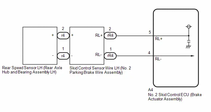 for AWD
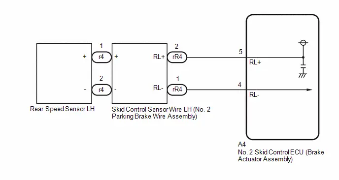
PROCEDURE
| 1. | CHECK Toyota Prius Vehicle |
| Result | Proceed to |
|---|---|
| for 2WD | A |
| for AWD | B |
| B |

| GO TO STEP 6 |
|

| 2. | CHECK HARNESS AND CONNECTOR (SENSOR GROUND CIRCUIT) |
Procedure1
(a) Make sure that there is no looseness at the locking part and the connecting part of the connectors.
OK:
The connector is securely connected.
Pre-procedure1
(b) Disconnect the r4 rear speed sensor LH (rear axle hub and bearing assembly LH) connector.
Procedure2
(c) Check both the connector case and the terminals for deformation and corrosion.
OK:
No deformation or corrosion.
Pre-procedure2
(d) Turn the ignition switch to ON.
Procedure3
(e) Measure the voltage according to the value(s) in the table below.
Standard Voltage:
 Click Location & Routing(r4) Click Connector(r4)
 | Tester Connection | Condition | Specified Condition | Result |
|---|---|---|---|
| r4-2 ( ) - r4-1 (-) | Ignition switch ON | 11 to 14 V | V |
HINT:
The rear speed sensor LH and rear speed sensor rotor LH are incorporated into the rear axle hub and bearing assembly LH.
If the rear speed sensor LH and rear speed sensor rotor LH need to be replaced, replace the rear axle hub and bearing assembly LH.
Post-procedure1
(f) None
| OK |

| REPLACE REAR AXLE HUB AND BEARING ASSEMBLY LH
|


|

| 3. | CHECK HARNESS AND CONNECTOR (SENSOR GROUND CIRCUIT) |
Pre-procedure1
(a) Turn the ignition switch off.
Procedure1
(b) Make sure that there is no looseness at the locking part and the connecting part of the connectors.
OK:
The connector is securely connected.
Pre-procedure2
(c) Disconnect the rR4 skid control sensor wire LH (No. 2 parking brake wire assembly) connector.
Procedure2
(d) Check both the connector case and the terminals for deformation and corrosion.
OK:
No deformation or corrosion.
Pre-procedure3
(e) Turn the ignition switch to ON.
Procedure3
| (f) Measure the voltage according to the value(s) in the table below. Standard Voltage:  Click Location & Routing(rR4) Click Connector(rR4) Click Location & Routing(rR4) Click Connector(rR4)
Result:
|
|

Post-procedure1
(g) None
| OK |

| REPLACE NO. 2 PARKING BRAKE WIRE ASSEMBLY |
|

| 4. | CHECK HARNESS AND CONNECTOR (SENSOR GROUND CIRCUIT) |
Pre-procedure1
(a) Turn the ignition switch off.
Procedure1
(b) Make sure that there is no looseness at the locking part and the connecting part of the connectors.
OK:
The connector is securely connected.
Pre-procedure2
(c) Disconnect the A4 No. 2 skid control ECU (brake actuator assembly) connector.
Procedure2
(d) Check both the connector case and the terminals for deformation and corrosion.
OK:
No deformation or corrosion.
Procedure3
| (e) Measure the voltage according to the value(s) in the table below. Standard Voltage:  Click Location & Routing(rR4) Click Connector(rR4) Click Location & Routing(rR4) Click Connector(rR4)
Result:
|
|

Post-procedure1
(f) None
| NG |

| REPAIR OR REPLACE HARNESS OR CONNECTOR |
|

| 5. | CHECK HARNESS AND CONNECTOR (NO. 2 PARKING BRAKE WIRE ASSEMBLY - BRAKE ACTUATOR ASSEMBLY) |
(a) Measure the resistance according to the value(s) in the table below.
Standard Resistance:
 Click Location & Routing(rR4,A4) Click Connector(rR4) Click Connector(A4)
 | Tester Connection | Condition | Specified Condition | Result |
|---|---|---|---|
| rR4-2 (RL ) or A4-5 (RL ) - rR4-1 (RL-) or A4-4 (RL-) | Always | 10 kΩ or higher | kΩ |
| OK |

| REPLACE BRAKE ACTUATOR ASSEMBLY
|


| NG |

| REPAIR OR REPLACE HARNESS OR CONNECTOR |
| 6. | CHECK HARNESS AND CONNECTOR (SENSOR GROUND CIRCUIT) |
Procedure1
(a) Make sure that there is no looseness at the locking part and the connecting part of the connectors.
OK:
The connector is securely connected.
Pre-procedure1
(b) Disconnect the r4 rear speed sensor LH connector.
Procedure2
(c) Check both the connector case and the terminals for deformation and corrosion.
OK:
No deformation or corrosion.
Pre-procedure2
(d) Turn the ignition switch to ON.
Procedure3
(e) Measure the voltage according to the value(s) in the table below.
Standard Voltage:
 Click Location & Routing(r4) Click Connector(r4)
 | Tester Connection | Condition | Specified Condition | Result |
|---|---|---|---|
| r4-1 ( ) - r4-2 (-) | Ignition switch ON | 11 to 14 V | V |
Post-procedure1
(f) None
| OK |

| REPLACE REAR SPEED SENSOR LH |
|

| 7. | CHECK HARNESS AND CONNECTOR (SENSOR GROUND CIRCUIT) |
Pre-procedure1
(a) Turn the ignition switch off.
Procedure1
(b) Make sure that there is no looseness at the locking part and the connecting part of the connectors.
OK:
The connector is securely connected.
Pre-procedure2
(c) Disconnect the rR4 skid control sensor wire LH (No. 2 parking brake wire assembly) connector.
Procedure2
(d) Check both the connector case and the terminals for deformation and corrosion.
OK:
No deformation or corrosion.
Pre-procedure3
(e) Turn the ignition switch to ON.
Procedure3
| (f) Measure the voltage according to the value(s) in the table below. Standard Voltage:  Click Location & Routing(rR4) Click Connector(rR4) Click Location & Routing(rR4) Click Connector(rR4)
Result:
|
|
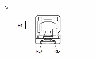
Post-procedure1
(g) None
| OK |

| REPLACE NO. 2 PARKING BRAKE WIRE ASSEMBLY |
|

| 8. | CHECK HARNESS AND CONNECTOR (SENSOR GROUND CIRCUIT) |
Pre-procedure1
(a) Turn the ignition switch off.
Procedure1
(b) Make sure that there is no looseness at the locking part and the connecting part of the connectors.
OK:
The connector is securely connected.
Pre-procedure2
(c) Disconnect the A4 No. 2 skid control ECU (brake actuator assembly) connector.
Procedure2
(d) Check both the connector case and the terminals for deformation and corrosion.
OK:
No deformation or corrosion.
Procedure3
| (e) Measure the voltage according to the value(s) in the table below. Standard Voltage:  Click Location & Routing(rR4) Click Connector(rR4) Click Location & Routing(rR4) Click Connector(rR4)
Result:
|
|

Post-procedure1
(f) None
| NG |

| REPAIR OR REPLACE HARNESS OR CONNECTOR |
|

| 9. | CHECK HARNESS AND CONNECTOR (NO. 2 PARKING BRAKE WIRE ASSEMBLY - BRAKE ACTUATOR ASSEMBLY) |
(a) Measure the resistance according to the value(s) in the table below.
Standard Resistance:
 Click Location & Routing(rR4,A4) Click Connector(rR4) Click Connector(A4)
 | Tester Connection | Condition | Specified Condition | Result |
|---|---|---|---|
| rR4-2 (RL ) or A4-5 (RL ) - rR4-1 (RL-) or A4-4 (RL-) | Always | 10 kΩ or higher | kΩ |
| OK |

| REPLACE BRAKE ACTUATOR ASSEMBLY
|


| NG |

| REPAIR OR REPLACE HARNESS OR CONNECTOR |
Left Rear Wheel Speed Sensor Circuit Short to Ground or Open (C050C14)
DESCRIPTION
Refer to DTC C050C12.
Click here

| DTC No. | Detection Item | DTC Detection Condition | Trouble Area | MIL | DTC Output from | Priority | Note |
|---|---|---|---|---|---|---|---|
| C050C14 | Left Rear Wheel Speed Sensor Circuit Short to Ground or Open | An open in the speed sensor signal circuit continues for 0.5 seconds or more. |
| Comes on | Brake/EPB | A |
|
- *1: for AWD
- *2: for 2WD
MONITOR DESCRIPTION
The No. 2 skid control ECU (brake actuator assembly) monitors the output of the speed sensors. When the output current of the speed sensor is excessively low, the MIL is illuminated and a DTC is stored.
MONITOR STRATEGY
| Related DTCs | C050E: Wheel speed sensor (RL) voltage circuit open |
| Required Sensors/Components(Main) | Speed sensor |
| Required Sensors/Components(Related) | No. 2 skid control ECU (brake actuator assembly) |
| Frequency of Operation | Continuous |
| Duration | 0.528 seconds |
| MIL Operation | Immediately |
| Sequence of Operation | None |
TYPICAL ENABLING CONDITIONS
| Monitor runs whenever the following DTCs are not stored | C0501 (Case 1): Wheel speed sensor (FL) range/performance (correlation A) C0501 (Case 2): Wheel speed sensor (FL) range/performance (2 wheels) C0501 (Case 3): Wheel speed sensor (FL) range/performance (correlation B) C0501 (Case 4): Wheel speed sensor (FL) range/performance (pulse output high) C0503: Wheel speed sensor (FL) voltage circuit high C0507 (Case 1): Wheel speed sensor (FR) range/performance (correlation A) C0507 (Case 2): Wheel speed sensor (FR) range/performance (2 wheels) C0507 (Case 3): Wheel speed sensor (FR) range/performance (correlation B) C0507 (Case 4): Wheel speed sensor (FR) range/performance (pulse output high) C0509: Wheel speed sensor (FR) voltage circuit high C050D (Case 1): Wheel speed sensor (RL) range/performance (correlation A) C050D (Case 2): Wheel speed sensor (RL) range/performance (2 wheels) C050D (Case 3): Wheel speed sensor (RL) range/performance (correlation B) C050D (Case 4): Wheel speed sensor (RL) range/performance (pulse output high) C050F: Wheel speed sensor (RL) voltage circuit high C0513 (Case 1): Wheel speed sensor (RR) range/performance (correlation A) C0513 (Case 2): Wheel speed sensor (RR) range/performance (2 wheels) C0513 (Case 3): Wheel speed sensor (RR) range/performance (correlation B) C0513 (Case 4): Wheel speed sensor (RR) range/performance (pulse output high) C0515: Wheel speed sensor (RR) voltage circuit high C137D: Brake system voltage circuit high C14E1 (Case 1): Wheel speed sensor (FL) voltage circuit low C14E1 (Case 2): Wheel speed sensor (FL) voltage circuit low (continuation) C14E4 (Case 1): Wheel speed sensor (FR) voltage circuit low C14E4 (Case 2): Wheel speed sensor (FR) voltage circuit low (continuation) C14E7 (Case 1): Wheel speed sensor (RL) voltage circuit low C14E7 (Case 2): Wheel speed sensor (RL) voltage circuit low (continuation) C14EA (Case 1): Wheel speed sensor (RR) voltage circuit low C14EA (Case 2): Wheel speed sensor (RR) voltage circuit low (continuation) |
| All of the following conditions are met | A, B, C, D, E, F, G and H |
| A. Following condition is met | More than 0.22 seconds |
| BS voltage | 17.4 V or less |
| B. Following condition is met | More than 0.22 seconds |
| BS voltage | 8.5 V or higher |
| C. Command to wheel speed sensor power supply | On |
| D. Following condition is met | More than 0.204 seconds |
| Wheel speed sensor power supply voltage low signal (IC Data) | Off |
| E. Wheel speed sensor overcurrent signal (IC Data) | Off |
| F. BS voltage | 9.5 V or higher |
| G. IGR voltage | Higher than 10 V |
| H. IGP voltage | Higher than 10 V |
TYPICAL MALFUNCTION THRESHOLDS
| Wheel speed sensor open circuit signal (IC Data) | On |
COMPONENT OPERATING RANGE
| Wheel speed sensor open circuit signal (IC Data) | Off |
CONFIRMATION DRIVING PATTERN
NOTICE:
When performing the normal judgment procedure, make sure that the driver door is closed and is not opened at any time during the procedure.
HINT:
- After repair has been completed, clear the DTC and then check that the Toyota Prius vehicle has returned to normal by performing the following All Readiness check procedure.
- When clearing the permanent DTCs, refer to the "CLEAR PERMANENT DTC" procedure.
- Connect the GTS to the DLC3.
- Turn the ignition switch to ON and turn the GTS on.
- Clear the DTCs (even if no DTCs are stored, perform the clear DTC procedure).
- Turn the ignition switch off.
- Turn the ignition switch to ON (READY) and turn the GTS on.
-
Wait for 2 seconds or more. [*]
HINT:
[*]: Normal judgment procedure.
The normal judgment procedure is used to complete DTC judgment and also used when clearing permanent DTCs.
-
Enter the following menus: Chassis / Brake/EPB* / Utility / All Readiness.
*: Electric Parking Brake System
-
Check the DTC judgment result.
HINT:
- If the judgment result shows NORMAL, the system is normal.
- If the judgment result shows ABNORMAL, the system has a malfunction.
- If the judgment result shows INCOMPLETE, perform driving pattern again.
WIRING DIAGRAM
Refer to DTC C050C12.
Click here

PROCEDURE
| 1. | READ VALUE USING GTS (MOMENTARY INTERRUPTION) |
Pre-procedure1
(a) Select the line graph display on the GTS.
Procedure1
(b) Check for any momentary interruption in the wire harness and connector.
Chassis > Brake/EPB > Data List| Tester Display | Measurement Item | Range | Normal Condition | Diagnostic Note |
|---|---|---|---|---|
| RL Speed Open | Rear speed sensor LH open detection | Normal / Under intermittent | Normal: Normal Under intermittent: Momentary interruption | - |
| RL Speed Sensor Voltage Open | Rear speed sensor LH voltage open detection | Normal / Under intermittent | Normal: Normal Under intermittent: Momentary interruption | - |
| Tester Display |
|---|
| RL Speed Open |
| RL Speed Sensor Voltage Open |
OK:
Normal (There are no momentary interruptions.)
NOTICE:
Perform the above inspection before removing the sensor and connector.
Post-procedure1
(c) None
| OK |

| USE SIMULATION METHOD TO CHECK |
|

| 2. | CHECK Toyota Prius Vehicle |
| Result | Proceed to |
|---|---|
| for 2WD | A |
| for AWD | B |
| B |

| GO TO STEP 6 |
|

| 3. | INSPECT NO. 2 PARKING BRAKE WIRE ASSEMBLY |
Pre-procedure1
(a) Turn the ignition switch off.
Procedure1
(b) Make sure that there is no looseness at the locking part and the connecting part of the connectors.
OK:
The connector is securely connected.
Pre-procedure2
(c) Disconnect the r4 and rR4 skid control sensor wire LH (No. 2 parking brake wire assembly) connector.
Procedure2
(d) Check both the connector case and the terminals for deformation and corrosion.
OK:
No deformation or corrosion.
Procedure3
| (e) Measure the resistance according to the value(s) in the table below. Standard Resistance:  Click Location & Routing(r4,rR4) Click Connector(r4) Click Connector(rR4) Click Location & Routing(r4,rR4) Click Connector(r4) Click Connector(rR4)
Result:
|
|
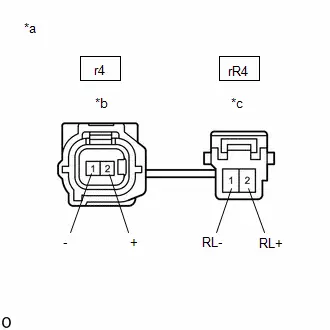
Post-procedure1
(f) None
| NG |

| REPLACE NO. 2 PARKING BRAKE WIRE ASSEMBLY |
|

| 4. | CHECK HARNESS AND CONNECTOR (NO. 2 PARKING BRAKE WIRE ASSEMBLY - BRAKE ACTUATOR ASSEMBLY) |
Procedure1
(a) Make sure that there is no looseness at the locking part and the connecting part of the connectors.
OK:
The connector is securely connected.
Pre-procedure1
(b) Disconnect the A4 No. 2 skid control ECU (brake actuator assembly) connector.
Procedure2
(c) Check both the connector case and the terminals for deformation and corrosion.
OK:
No deformation or corrosion.
Procedure3
(d) Measure the resistance according to the value(s) in the table below.
Standard Resistance:
 Click Location & Routing(rR4,A4) Click Connector(rR4) Click Connector(A4)
 | Tester Connection | Condition | Specified Condition | Result |
|---|---|---|---|
| rR4-2 (RL ) - A4-5 (RL ) | Always | Below 1 Ω | Ω |
| rR4-2 (RL ) or A4-5 (RL ) - Body ground | Always | 10 kΩ or higher | kΩ |
| rR4-1 (RL-) - A4-4 (RL-) | Always | Below 1 Ω | Ω |
| rR4-1 (RL-) or A4-4 (RL-) - Body ground | Always | 10 kΩ or higher | kΩ |
Post-procedure1
(e) None
| NG |

| REPAIR OR REPLACE HARNESS OR CONNECTOR |
|

| 5. | INSPECT BRAKE ACTUATOR ASSEMBLY (SENSOR POWER SOURCE CIRCUIT) |
Pre-procedure1
(a) Reconnect the A4 No. 2 skid control ECU (brake actuator assembly) connector.
(b) Reconnect the rR4 skid control sensor wire LH (No. 2 parking brake wire assembly) connector.
(c) Turn the ignition switch to ON.
Procedure1
(d) Measure the voltage according to the value(s) in the table below.
Standard Voltage:
 Click Location & Routing(r4) Click Connector(r4)
 | Tester Connection | Condition | Specified Condition | Result |
|---|---|---|---|
| r4-2 ( ) - Body ground | Ignition switch ON | 11 to 14 V | V |
HINT:
The rear speed sensor LH and rear speed sensor rotor LH are incorporated into the rear axle hub and bearing assembly LH.
If the rear speed sensor LH and rear speed sensor rotor LH need to be replaced, replace the rear axle hub and bearing assembly LH.
Post-procedure1
(e) None
| OK |

| REPLACE REAR AXLE HUB AND BEARING ASSEMBLY LH
|


| NG |

| REPLACE BRAKE ACTUATOR ASSEMBLY
|


| 6. | INSPECT NO. 2 PARKING BRAKE WIRE ASSEMBLY |
Pre-procedure1
(a) Turn the ignition switch off.
Procedure1
(b) Make sure that there is no looseness at the locking part and the connecting part of the connectors.
OK:
The connector is securely connected.
Pre-procedure2
(c) Disconnect the r4 and rR4 skid control sensor wire LH (No. 2 parking brake wire assembly) connector.
Procedure2
(d) Check both the connector case and the terminals for deformation and corrosion.
OK:
No deformation or corrosion.
Procedure3
| (e) Measure the resistance according to the value(s) in the table below. Standard Resistance:  Click Location & Routing(r4,rR4) Click Connector(r4) Click Connector(rR4) Click Location & Routing(r4,rR4) Click Connector(r4) Click Connector(rR4)
Result:
|
|
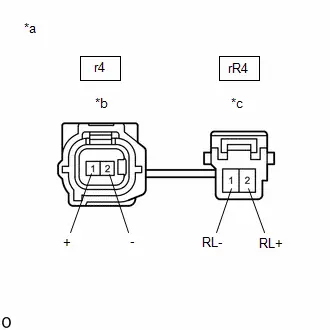
Post-procedure1
(f) None
| NG |

| REPLACE NO. 2 PARKING BRAKE WIRE ASSEMBLY |
|

| 7. | CHECK HARNESS AND CONNECTOR (NO. 2 PARKING BRAKE WIRE ASSEMBLY - BRAKE ACTUATOR ASSEMBLY) |
Procedure1
(a) Make sure that there is no looseness at the locking part and the connecting part of the connectors.
OK:
The connector is securely connected.
Pre-procedure1
(b) Disconnect the A4 No. 2 skid control ECU (brake actuator assembly) connector.
Procedure2
(c) Check both the connector case and the terminals for deformation and corrosion.
OK:
No deformation or corrosion.
Procedure3
(d) Measure the resistance according to the value(s) in the table below.
Standard Resistance:
 Click Location & Routing(rR4,A4) Click Connector(rR4) Click Connector(A4)
 | Tester Connection | Condition | Specified Condition | Result |
|---|---|---|---|
| rR4-2 (RL ) - A4-5 (RL ) | Always | Below 1 Ω | Ω |
| rR4-2 (RL ) or A4-5 (RL ) - Body ground | Always | 10 kΩ or higher | kΩ |
| rR4-1 (RL-) - A4-4 (RL-) | Always | Below 1 Ω | Ω |
| rR4-1 (RL-) or A4-4 (RL-) - Body ground | Always | 10 kΩ or higher | kΩ |
Post-procedure1
(e) None
| NG |

| REPAIR OR REPLACE HARNESS OR CONNECTOR |
|

| 8. | INSPECT BRAKE ACTUATOR ASSEMBLY (SENSOR POWER SOURCE CIRCUIT) |
Pre-procedure1
(a) Reconnect the A4 No. 2 skid control ECU (brake actuator assembly) connector.
(b) Reconnect the rR4 skid control sensor wire LH (No. 2 parking brake wire assembly) connector.
(c) Turn the ignition switch to ON.
Procedure1
(d) Measure the voltage according to the value(s) in the table below.
Standard Voltage:
 Click Location & Routing(r4) Click Connector(r4)
 | Tester Connection | Condition | Specified Condition | Result |
|---|---|---|---|
| r4-1 ( ) - Body ground | Ignition switch ON | 11 to 14 V | V |
Post-procedure1
(e) None
| OK |

| REPLACE REAR SPEED SENSOR LH |
| NG |

| REPLACE BRAKE ACTUATOR ASSEMBLY
|


Left Rear Wheel Speed Sensor Signal Stuck Low (C050C23)
DESCRIPTION
Refer to DTC C050C12.
Click here

| DTC No. | Detection Item | DTC Detection Condition | Trouble Area | MIL | DTC Output from | Priority | Note |
|---|---|---|---|---|---|---|---|
| C050C23 | Left Rear Wheel Speed Sensor Signal Stuck Low | Any of the following is detected:
|
| Comes on | Brake/EPB | A |
|
- *1: for AWD
- *2: for 2WD
MONITOR DESCRIPTION
-
When the Toyota Prius vehicle is being driven, if the value of the speed sensor which is outputting the lowest vehicle speed is significantly lower than the values of the other speed sensors, or the value of the speed sensor which is outputting the lowest vehicle speed is 0 km/h (0 mph), the No. 2 skid control ECU (brake actuator assembly) judges that the speed sensor is malfunctioning and illuminates the MIL and stores this DTC.
Also, when a wheel speed is being output (the wheel is not locked), if the output values of the speed sensors for 2 wheels are stuck at 0 km/h (0 mph), the No. 2 skid control ECU (brake actuator assembly) judges that a speed sensor is malfunctioning and illuminates the MIL and stores this DTC.
- When the Toyota Prius vehicle is being driven at a certain speed or more, the rotational direction of 3 wheels is determined, and the rotational direction of 1 wheel is not determined for a certain amount of time, the No. 2 skid control ECU (brake actuator assembly) judges that the speed sensor is malfunctioning and illuminates the MIL and stores this DTC.
MONITOR STRATEGY
| Related DTCs | C050D (Case 1): Wheel speed sensor (RL) range/performance (correlation A) C050D (Case 2): Wheel speed sensor (RL) range/performance (2 wheels) C050D (Case 3): Wheel speed sensor (RL) range/performance (correlation B) C050D (Case 5): Wheel speed sensor (RL) range/performance (rotatory direction) |
| Required Sensors/Components(Main) | Speed sensor Speed sensor rotor |
| Required Sensors/Components(Related) | No. 2 skid control ECU (brake actuator assembly) Stop light switch assembly Speed sensor |
| Frequency of Operation | Continuous |
| Duration | 1 second: C050D (Case 3) 3 seconds: C050D (Case 5) 30 seconds: C050D (Case 1 and 2) |
| MIL Operation | Immediately |
| Sequence of Operation | None |
TYPICAL ENABLING CONDITIONS
Case 1| Monitor runs whenever the following DTCs are not stored | C0501 (Case 2): Wheel speed sensor (FL) range/performance (2 wheels) C0501 (Case 4): Wheel speed sensor (FL) range/performance (pulse output high) C0502: Wheel speed sensor (FL) voltage circuit open C0503: Wheel speed sensor (FL) voltage circuit high C0504 (Case 1): Wheel speed sensor (FL) intermittent/erratic (moment open) C0504 (Case 2): Wheel speed sensor (FL) intermittent/erratic (a piece of metal noise) C0504 (Case 3): Wheel speed sensor (FL) intermittent/erratic (a piece of metal rotor noise) C0507 (Case 2): Wheel speed sensor (FR) range/performance (2 wheels) C0507 (Case 4): Wheel speed sensor (FR) range/performance (pulse output high) C0508: Wheel speed sensor (FR) voltage circuit open C0509: Wheel speed sensor (FR) voltage circuit high C050A (Case 1): Wheel speed sensor (FR) intermittent/erratic (moment open) C050A (Case 2): Wheel speed sensor (FR) intermittent/erratic (a piece of metal noise) C050A (Case 3): Wheel speed sensor (FR) intermittent/erratic (a piece of metal rotor noise) C050D (Case 2): Wheel speed sensor (RL) range/performance (2 wheels) C050D (Case 4): Wheel speed sensor (RL) range/performance (pulse output high) C050E: Wheel speed sensor (RL) voltage circuit open C050F: Wheel speed sensor (RL) voltage circuit high C0510 (Case 1): Wheel speed sensor (RL) intermittent/erratic (moment open) C0510 (Case 2): Wheel speed sensor (RL) intermittent/erratic (a piece of metal noise) C0510 (Case 3): Wheel speed sensor (RL) intermittent/erratic (a piece of metal rotor noise) C0513 (Case 2): Wheel speed sensor (RR) range/performance (2 wheels) C0513 (Case 4): Wheel speed sensor (RR) range/performance (pulse output high) C0514: Wheel speed sensor (RR) voltage circuit open C0515: Wheel speed sensor (RR) voltage circuit high C0516 (Case 1): Wheel speed sensor (RR) intermittent/erratic (moment open) C0516 (Case 2): Wheel speed sensor (RR) intermittent/erratic (a piece of metal noise) C0516 (Case 3): Wheel speed sensor (RR) intermittent/erratic (a piece of metal rotor noise) C137D: Brake system voltage circuit high C14E1 (Case 1): Wheel speed sensor (FL) voltage circuit low C14E1 (Case 2): Wheel speed sensor (FL) voltage circuit low (continuation) C14E4 (Case 1): Wheel speed sensor (FR) voltage circuit low C14E4 (Case 2): Wheel speed sensor (FR) voltage circuit low (continuation) C14E7 (Case 1): Wheel speed sensor (RL) voltage circuit low C14E7 (Case 2): Wheel speed sensor (RL) voltage circuit low (continuation) C14EA (Case 1): Wheel speed sensor (RR) voltage circuit low C14EA (Case 2): Wheel speed sensor (RR) voltage circuit low (continuation) |
| All of the following conditions are met | A, B, C, D, E, F, G and H |
| A. Chassis dynamometer mode | Off |
| B. Following condition is met | More than 0.012 seconds |
| IGR voltage | 3.5 V or higher |
| C. Command to all ABS hold solenoids | Off |
| D. Command to all ABS release solenoids | Off |
| E. Following condition is met | More than 0.22 seconds |
| BS voltage | 17.4 V or less |
| F. Difference between the highest speed sensor output value and the second lowest speed sensor output value | Less than 20% of the highest speed sensor output value |
| G. The second lowest speed sensor output value | 60 Hz 2 km/h (1.24 mph) or more |
| H. IGP voltage | Higher than 10 V |
| Monitor runs whenever the following DTCs are not stored | C0501 (Case 4): Wheel speed sensor (FL) range/performance (pulse output high) C0502: Wheel speed sensor (FL) voltage circuit open C0503: Wheel speed sensor (FL) voltage circuit high C0504 (Case 1): Wheel speed sensor (FL) intermittent/erratic (moment open) C0504 (Case 2): Wheel speed sensor (FL) intermittent/erratic (a piece of metal noise) C0504 (Case 3): Wheel speed sensor (FL) intermittent/erratic (a piece of metal rotor noise) C0507 (Case 4): Wheel speed sensor (FR) range/performance (pulse output high) C0508: Wheel speed sensor (FR) voltage circuit open C0509: Wheel speed sensor (FR) voltage circuit high C050A (Case 1): Wheel speed sensor (FR) intermittent/erratic (moment open) C050A (Case 2): Wheel speed sensor (FR) intermittent/erratic (a piece of metal noise) C050A (Case 3): Wheel speed sensor (FR) intermittent/erratic (a piece of metal rotor noise) C050D (Case 4): Wheel speed sensor (RL) range/performance (pulse output high) C050E: Wheel speed sensor (RL) voltage circuit open C050F: Wheel speed sensor (RL) voltage circuit high C0510 (Case 1): Wheel speed sensor (RL) intermittent/erratic (moment open) C0510 (Case 2): Wheel speed sensor (RL) intermittent/erratic (a piece of metal noise) C0510 (Case 3): Wheel speed sensor (RL) intermittent/erratic (a piece of metal rotor noise) C0513 (Case 4): Wheel speed sensor (RR) range/performance (pulse output high) C0514: Wheel speed sensor (RR) voltage circuit open C0515: Wheel speed sensor (RR) voltage circuit high C0516 (Case 1): Wheel speed sensor (RR) intermittent/erratic (moment open) C0516 (Case 2): Wheel speed sensor (RR) intermittent/erratic (a piece of metal noise) C0516 (Case 3): Wheel speed sensor (RR) intermittent/erratic (a piece of metal rotor noise) C137D: Brake system voltage circuit high C14E1 (Case 1): Wheel speed sensor (FL) voltage circuit low C14E1 (Case 2): Wheel speed sensor (FL) voltage circuit low (continuation) C14E4 (Case 1): Wheel speed sensor (FR) voltage circuit low C14E4 (Case 2): Wheel speed sensor (FR) voltage circuit low (continuation) C14E7 (Case 1): Wheel speed sensor (RL) voltage circuit low C14E7 (Case 2): Wheel speed sensor (RL) voltage circuit low (continuation) C14EA (Case 1): Wheel speed sensor (RR) voltage circuit low C14EA (Case 2): Wheel speed sensor (RR) voltage circuit low (continuation) |
| All of the following conditions are met | A, B, C, D, E, F, G, H and I |
| A. Chassis dynamometer mode | Off |
| B. Following condition is met | More than 0.012 seconds |
| IGR voltage | 3.5 V or higher |
| C. Command to all ABS hold solenoids | Off |
| D. Command to all ABS release solenoids | Off |
| E. Following condition is met | More than 0.22 seconds |
| BS voltage | 17.4 V or less |
| F. Brake pedal operation | Off |
| G. Parking brake | Off |
| H. Difference between the highest speed sensor output value and the second highest speed sensor output value | Less than 20% of the highest speed sensor output value |
| I. The second highest speed sensor output value | 60 Hz 2 km/h (1.24 mph) or more |
| Monitor runs whenever the following DTCs are not stored | C0501 (Case 1): Wheel speed sensor (FL) range/performance (correlation A) C0501 (Case 2): Wheel speed sensor (FL) range/performance (2 wheels) C0501 (Case 3): Wheel speed sensor (FL) range/performance (correlation B) C0501 (Case 4): Wheel speed sensor (FL) range/performance (pulse output high) C0502: Wheel speed sensor (FL) voltage circuit open C0503: Wheel speed sensor (FL) voltage circuit high C0504 (Case 1): Wheel speed sensor (FL) intermittent/erratic (moment open) C0504 (Case 2): Wheel speed sensor (FL) intermittent/erratic (a piece of metal noise) C0504 (Case 3): Wheel speed sensor (FL) intermittent/erratic (a piece of metal rotor noise) C0507 (Case 1): Wheel speed sensor (FR) range/performance (correlation A) C0507 (Case 2): Wheel speed sensor (FR) range/performance (2 wheels) C0507 (Case 3): Wheel speed sensor (FR) range/performance (correlation B) C0507 (Case 4): Wheel speed sensor (FR) range/performance (pulse output high) C0508: Wheel speed sensor (FR) voltage circuit open C0509: Wheel speed sensor (FR) voltage circuit high C0510 (Case 1): Wheel speed sensor (RL) intermittent/erratic (moment open) C0510 (Case 2): Wheel speed sensor (RL) intermittent/erratic (a piece of metal noise) C0510 (Case 3): Wheel speed sensor (RL) intermittent/erratic (a piece of metal rotor noise) C0513 (Case 1): Wheel speed sensor (RR) range/performance (correlation A) C0513 (Case 2): Wheel speed sensor (RR) range/performance (2 wheels) C0513 (Case 3): Wheel speed sensor (RR) range/performance (correlation B) C0513 (Case 4): Wheel speed sensor (RR) range/performance (pulse output high) C0514: Wheel speed sensor (RR) voltage circuit open C0515: Wheel speed sensor (RR) voltage circuit high C0516 (Case 1): Wheel speed sensor (RR) intermittent/erratic (moment open) C0516 (Case 2): Wheel speed sensor (RR) intermittent/erratic (a piece of metal noise) C0516 (Case 3): Wheel speed sensor (RR) intermittent/erratic (a piece of metal rotor noise) C050A (Case 1): Wheel speed sensor (FR) intermittent/erratic (moment open) C050A (Case 2): Wheel speed sensor (FR) intermittent/erratic (a piece of metal noise) C050A (Case 3): Wheel speed sensor (FR) intermittent/erratic (a piece of metal rotor noise) C050D (Case 1): Wheel speed sensor (RL) range/performance (correlation A) C050D (Case 2): Wheel speed sensor (RL) range/performance (2 wheels) C050D (Case 4): Wheel speed sensor (RL) range/performance (pulse output high) C050E: Wheel speed sensor (RL) voltage circuit open C050F: Wheel speed sensor (RL) voltage circuit high C051C (Case 1): Acceleration sensor range/Performance (acceleration sensor lock) C051C (Case 2): Acceleration sensor range/Performance (GL1, GL2 lock) C051C (Case 3): Acceleration sensor range/Performance (acceleration sensor output) C051D: Acceleration sensor missing calibration C051E: Acceleration sensor intermittent/erratic C0520 (Case 1): Acceleration sensor (GL1, GL2) out of range C0520 (Case 2): Acceleration sensor GL2 out of range C0520 (Case 3): Acceleration sensor internal check C052B (Case 1 to 7): ABS pump motor performance (gate voltage) C052B (Case 8): ABS pump motor performance (motor relay current) C052B (Case 9): ABS pump motor performance (freewheeling MOS current) C052D: ABS pump motor circuit high C052E (Case 1 to 4): ABS pump motor circuit open (motor circuit) C052E (Case 5 and 6): ABS pump motor circuit open (motor relay) C053D: Master cylinder pressure sensor exceeded learning limit C0540 (Case 1): Pressure sensor lost communication C0540 (Case 2): Pressure sensor internal check C0540 (Case 3): Pressure sensor invalid data C0555: Wheel speed sensor (FL) range/performance C0556: Wheel speed sensor (FR) range/performance C0557: Wheel speed sensor (RL) range/performance C0558: Wheel speed sensor (RR) range/performance C056B: Pressure sensor intermittent/erratic C0597: ABS hold solenoid performance C05C1: Brake pedal position sensor learning not complete C1103 (Case 1): Brake pedal position sensor voltage circuit open C122E: Pressure sensor voltage circuit low C122F: Pressure sensor voltage circuit high C1240: Yaw rate and acceleration sensor incorrect C124A: Identification signal C12A7 (Case 1 and 2): ABS hold solenoid (FL) circuit open C12A7 (Case 3): ABS hold solenoid (FL) circuit low C12A8 (Case 1): ABS hold solenoid (FL) circuit high (solenoid Off current) C12A8 (Case 2 and 3): ABS hold solenoid (FL) circuit high (IC data) C12A8 (Case 4): ABS hold solenoid (FL) circuit high (solenoid On current) C12B2: ABS release solenoid (FL) circuit low C12B3: ABS release solenoid (FL) circuit high C12BD (Case 1 and 2): ABS hold solenoid (FR) circuit open C12BD (Case 3): ABS hold solenoid (FR) circuit low C12BE (Case 1): ABS hold solenoid (FR) circuit high (solenoid Off current) C12BE (Case 2 and 3): ABS hold solenoid (FR) circuit high (IC data) C12BE (Case 4): ABS hold solenoid (FR) circuit high (solenoid On current) C12C8: ABS release solenoid (FR) circuit low C12C9: ABS release solenoid (FR) circuit high C12D3 (Case 1 and 2): ABS hold solenoid (RL) circuit open C12D3 (Case 3): ABS hold solenoid (RL) circuit low C12D4 (Case 1): ABS hold solenoid (RL) circuit high (solenoid Off current) C12D4 (Case 2 and 3): ABS hold solenoid (RL) circuit high (IC data) C12D4 (Case 4): ABS hold solenoid (RL) circuit high (solenoid On current) C12DE: ABS release solenoid (RL) circuit low C12DF: ABS release solenoid (RL) circuit high C12E9 (Case 1 and 2): ABS hold solenoid (RR) circuit open C12E9 (Case 3): ABS hold solenoid (RR) circuit low C12EA (Case 1): ABS hold solenoid (RR) circuit high (solenoid Off current) C12EA (Case 2 and 3): ABS hold solenoid (RR) circuit high (IC data) C12EA (Case 4): ABS hold solenoid (RR) circuit high (solenoid On current) C12F4: ABS release solenoid (RR) circuit low C12F5: ABS release solenoid (RR) circuit high C12F6: ABS hold solenoid other functional C12F7: ABS hold solenoid other functional C13BF: SM solenoid other functional C13C2 (Case 1 and 2): SM1 solenoid circuit open C13C2 (Case 3): SM1 solenoid circuit low C13C3 (Case 1): SM1 solenoid circuit high (solenoid Off current) C13C3 (Case 2 and 3): SM1 solenoid circuit high (IC data) C13C3 (Case 4): SM1 solenoid circuit high (solenoid On current) C13CB (Case 1 and 2): SM2 solenoid circuit open C13CB (Case 3): SM2 solenoid circuit low C13CC (Case 1): SM2 solenoid circuit high (solenoid Off current) C13CC (Case 2 and 3): SM2 solenoid circuit high (IC data) C13CC (Case 4): SM2 solenoid circuit high (solenoid On current) C137D: Brake system voltage circuit high C1427: ABS pump motor stuck C143B: Brake system voltage power supply relay circuit high C143C: Brake system voltage power supply relay circuit open C14E1 (Case 1): Wheel speed sensor (FL) voltage circuit low C14E1 (Case 2): Wheel speed sensor (FL) voltage circuit low (continuation) C14E4 (Case 1): Wheel speed sensor (FR) voltage circuit low C14E4 (Case 2): Wheel speed sensor (FR) voltage circuit low (continuation) C14E7 (Case 1): Wheel speed sensor (RL) voltage circuit low C14E7 (Case 2): Wheel speed sensor (RL) voltage circuit low (continuation) C14EA (Case 1): Wheel speed sensor (RR) voltage circuit low C14EA (Case 2): Wheel speed sensor (RR) voltage circuit low (continuation) P05DB: Brake pedal position sensor invalid data P05DD: Brake pedal position sensor circuit open P05DE: Brake pedal position sensor circuit high P05DF: Brake pedal position sensor intermittent/erratic P05E0: Brake pedal position sensor "A"/"B" correlation U0125: Lost communication with multi-axis acceleration sensor module |
| All of the following conditions are met | A, B, C, D, E, F, G, H and I |
| A. Chassis dynamometer mode | Off |
| B. Following condition is met | More than 0.012 seconds |
| IGR voltage | 3.5 V or higher |
| C. Command to all ABS hold solenoids | Off |
| D. Command to all ABS release solenoids | Off |
| E. Following condition is met | More than 0.22 seconds |
| BS voltage | 17.4 V or less |
| F. Brake pedal operation | Off |
| G. Parking brake | Off |
| H. Difference between the highest speed sensor output value and the second lowest speed sensor output value | Less than 2 km/h (1.24 mph) |
| I. BM voltage | 6 V or higher |
| Monitor runs whenever the following DTCs are not stored | C0501 (Case 4): Wheel speed sensor (FL) range/performance (pulse output high) C0502: Wheel speed sensor (FL) voltage circuit open C0503: Wheel speed sensor (FL) voltage circuit high C0504 (Case 1): Wheel speed sensor (FL) intermittent/erratic (moment open) C0504 (Case 2): Wheel speed sensor (FL) intermittent/erratic (a piece of metal noise) C0504 (Case 3): Wheel speed sensor (FL) intermittent/erratic (a piece of metal rotor noise) C0507 (Case 4): Wheel speed sensor (FR) range/performance (pulse output high) C0508: Wheel speed sensor (FR) voltage circuit open C0509: Wheel speed sensor (FR) voltage circuit high C050A (Case 1): Wheel speed sensor (FR) intermittent/erratic (moment open) C050A (Case 2): Wheel speed sensor (FR) intermittent/erratic (a piece of metal noise) C050A (Case 3): Wheel speed sensor (FR) intermittent/erratic (a piece of metal rotor noise) C050D (Case 4): Wheel speed sensor (RL) range/performance (pulse output high) C050E: Wheel speed sensor (RL) voltage circuit open C050F: Wheel speed sensor (RL) voltage circuit high C0510 (Case 1): Wheel speed sensor (RL) intermittent/erratic (moment open) C0510 (Case 2): Wheel speed sensor (RL) intermittent/erratic (a piece of metal noise) C0510 (Case 3): Wheel speed sensor (RL) intermittent/erratic (a piece of metal rotor noise) C0513 (Case 4): Wheel speed sensor (RR) range/performance (pulse output high) C0514: Wheel speed sensor (RR) voltage circuit open C0515: Wheel speed sensor (RR) voltage circuit high C0516 (Case 1): Wheel speed sensor (RR) intermittent/erratic (moment open) C0516 (Case 2): Wheel speed sensor (RR) intermittent/erratic (a piece of metal noise) C0516 (Case 3): Wheel speed sensor (RR) intermittent/erratic (a piece of metal rotor noise) C137D: Brake system voltage circuit high C14E1 (Case 1): Wheel speed sensor (FL) voltage circuit low C14E1 (Case 2): Wheel speed sensor (FL) voltage circuit low (continuation) C14E4 (Case 1): Wheel speed sensor (FR) voltage circuit low C14E4 (Case 2): Wheel speed sensor (FR) voltage circuit low (continuation) C14E7 (Case 1): Wheel speed sensor (RL) voltage circuit low C14E7 (Case 2): Wheel speed sensor (RL) voltage circuit low (continuation) C14EA (Case 1): Wheel speed sensor (RR) voltage circuit low C14EA (Case 2): Wheel speed sensor (RR) voltage circuit low (continuation) |
| All of the following conditions are met | - |
| Chassis dynamometer mode | Off |
| Command to all ABS hold solenoids | Off |
| Command to all ABS release solenoids | Off |
| Difference between the highest speed sensor output value and the lowest speed sensor output value | Less than 10% of the highest speed sensor output value |
| Lowest speed sensor output value | Higher than 30 km/h (18.64 mph) |
TYPICAL MALFUNCTION THRESHOLDS
Case 1| One-seventh of the second lowest speed sensor output value | Higher than the lowest speed sensor output value |
| Second lowest speed sensor output value | 0 km/h (0 mph) |
| Both of the following conditions are met | - |
| Lowest speed sensor output value | 0 km/h (0 mph) |
| The lowest speed sensor value changes from less than 60 Hz 2 km/h (1.24 mph) to 60 Hz 2 km/h (1.24 mph) or more | - |
| Both of the following conditions are met | - |
| Direction of 3 wheels | Determined |
| Direction of 1 wheel | Undetermined |
COMPONENT OPERATING RANGE
Case 1 to 3| All of the following conditions are met | - |
| Chassis dynamometer mode | Off |
| Wheel speed sensor fail (C0502, C0503, C0508, C0509, C050E, C050F, C0514, C0515) | Not detected |
| Wheel speed sensor voltage circuit low fail (C14E1, C14E4, C14E7, C14EA) | Not detected |
| Noise recovery experience | On |
| A piece of metal rotor noise recovery experience | On |
| Low speed recovery experience | On |
| All of the following conditions are met | - |
| Chassis dynamometer mode | Off |
| Command to all ABS hold solenoids | Off |
| Command to all ABS release solenoids | Off |
| Difference between the highest speed sensor output value and the lowest speed sensor output value | Less than 10% of the highest speed sensor output value |
| Lowest speed sensor output value | Higher than 30 km/h (18.64 mph) |
| Direction of 4 wheels | Determined |
CONFIRMATION DRIVING PATTERN
NOTICE:
When performing the normal judgment procedure, make sure that the driver door is closed and is not opened at any time during the procedure.
HINT:
- After repair has been completed, clear the DTC and then check that the Toyota Prius vehicle has returned to normal by performing the following All Readiness check procedure.
- When clearing the permanent DTCs, refer to the "CLEAR PERMANENT DTC" procedure.
- Connect the GTS to the DLC3.
- Turn the ignition switch to ON and turn the GTS on.
- Clear the DTCs (even if no DTCs are stored, perform the clear DTC procedure).
- Turn the ignition switch off.
- Turn the ignition switch to ON (READY) and turn the GTS on.
-
Drive the Toyota Prius vehicle straight at a speed of 20 km/h (12 mph) or more for 30 seconds or more. [*]
HINT:
[*]: Normal judgment procedure.
The normal judgment procedure is used to complete DTC judgment and also used when clearing permanent DTCs.
-
Enter the following menus: Chassis / Brake/EPB* / Utility / All Readiness.
*: Electric Parking Brake System
-
Check the DTC judgment result.
HINT:
- If the judgment result shows NORMAL, the system is normal.
- If the judgment result shows ABNORMAL, the system has a malfunction.
- If the judgment result shows INCOMPLETE, perform driving pattern again.
WIRING DIAGRAM
Refer to DTC C050C12.
Click here

PROCEDURE
| 1. | CHECK Toyota Prius Vehicle |
| Result | Proceed to |
|---|---|
| for 2WD | A |
| for AWD | B |
| B |

| GO TO STEP 6 |
|

| 2. | CHECK REAR SPEED SENSOR LH INSTALLATION |
| (a) Check the rear speed sensor LH installation. OK: There is no clearance between the rear speed sensor LH and the rear axle hub and bearing assembly LH. HINT: The rear speed sensor rotor LH and rear speed sensor LH are incorporated into the rear axle hub and bearing assembly LH. If the rear speed sensor rotor LH needs to be replaced, replace the rear axle hub and bearing assembly LH with rear speed sensor LH. |
|
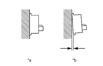
| NG |

| REPLACE REAR AXLE HUB AND BEARING ASSEMBLY LH
|


|

| 3. | READ VALUE USING GTS (RL WHEEL SPEED) |
Pre-procedure1
(a) Perform a road test.
Procedure1
(b) Check the rear speed sensor LH (rear axle hub and bearing assembly LH) output value.
Chassis > Brake/EPB > Data List| Tester Display | Measurement Item | Range | Normal Condition | Diagnostic Note |
|---|---|---|---|---|
| RL Wheel Speed | Rear wheel speed sensor LH reading | Min.: 0.0 km/h (0 mph) Max.: 6553.5 km/h (4072 mph) | Toyota Prius Vehicle stopped: 0.0 km/h (0 mph) | When driving at constant speed: No large fluctuations |
| Tester Display |
|---|
| RL Wheel Speed |
OK:
The output value changes in accordance with the Toyota Prius vehicle speed.
Post-procedure1
(c) None
| OK |

| USE SIMULATION METHOD TO CHECK |
|

| 4. | INSPECT NO. 2 PARKING BRAKE WIRE ASSEMBLY |
Pre-procedure1
(a) Turn the ignition switch off.
Procedure1
(b) Make sure that there is no looseness at the locking part and the connecting part of the connectors.
OK:
The connector is securely connected.
Pre-procedure2
(c) Disconnect the r4 and rR4 skid control sensor wire LH (No. 2 parking brake wire assembly) connector.
Procedure2
(d) Check both the connector case and the terminals for deformation and corrosion.
OK:
No deformation or corrosion.
Procedure3
| (e) Measure the resistance according to the value(s) in the table below. Standard Resistance:  Click Location & Routing(r4,rR4) Click Connector(r4) Click Connector(rR4) Click Location & Routing(r4,rR4) Click Connector(r4) Click Connector(rR4)
Result:
|
|

Post-procedure1
(f) None
| NG |

| REPLACE NO. 2 PARKING BRAKE WIRE ASSEMBLY |
|

| 5. | CHECK HARNESS AND CONNECTOR (NO. 2 PARKING BRAKE WIRE ASSEMBLY - BRAKE ACTUATOR ASSEMBLY) |
Procedure1
(a) Make sure that there is no looseness at the locking part and the connecting part of the connectors.
OK:
The connector is securely connected.
Pre-procedure1
(b) Disconnect the A4 No. 2 skid control ECU (brake actuator assembly) connector.
Procedure2
(c) Check both the connector case and the terminals for deformation and corrosion.
OK:
No deformation or corrosion.
Procedure3
(d) Measure the resistance according to the value(s) in the table below.
Standard Resistance:
 Click Location & Routing(rR4,A4) Click Connector(rR4) Click Connector(A4)
 | Tester Connection | Condition | Specified Condition | Result |
|---|---|---|---|
| rR4-2 (RL ) - A4-5 (RL ) | Always | Below 1 Ω | Ω |
| rR4-2 (RL ) or A4-5 (RL ) - Body ground | Always | 10 kΩ or higher | kΩ |
| rR4-1 (RL-) - A4-4 (RL-) | Always | Below 1 Ω | Ω |
| rR4-1 (RL-) or A4-4 (RL-) - Body ground | Always | 10 kΩ or higher | kΩ |
HINT:
The rear speed sensor LH and rear speed sensor rotor LH are incorporated into the rear axle hub and bearing assembly LH.
If the rear speed sensor LH and rear speed sensor rotor LH need to be replaced, replace the rear axle hub and bearing assembly LH.
Post-procedure1
(e) None
| OK |

| REPLACE REAR AXLE HUB AND BEARING ASSEMBLY LH
|


| NG |

| REPAIR OR REPLACE HARNESS OR CONNECTOR |
| 6. | CHECK REAR SPEED SENSOR LH INSTALLATION |
| (a) Check the rear speed sensor LH installation. OK: There is no clearance between the rear speed sensor LH and the rear axle carrier LH. The installation bolt is tightened properly. |
|

| NG |

| REINSTALL OR REPLACE REAR SPEED SENSOR LH |
|

| 7. | CHECK REAR SPEED SENSOR LH (CHECK FOR FOREIGN MATTER) |
Pre-procedure1
(a) Remove the rear speed sensor LH.
HINT:
Click here

Procedure1
(b) Check the rear speed sensor tip LH.
OK:
The rear speed sensor tip LH is free of scratches, oil, and foreign matter.
NOTICE:
- If there is oil or foreign matter on the rear speed sensor LH, clean the rear speed sensor LH.
- If the rear speed sensor LH is damaged, replace the rear speed sensor LH with a new one.
Post-procedure1
(c) None
| NG |

| CLEAN OR REPLACE REAR SPEED SENSOR LH |
|

| 8. | READ VALUE USING GTS (RL WHEEL SPEED) |
Pre-procedure1
(a) Perform a road test.
Procedure1
(b) Check the rear speed sensor LH output value.
Chassis > Brake/EPB > Data List| Tester Display | Measurement Item | Range | Normal Condition | Diagnostic Note |
|---|---|---|---|---|
| RL Wheel Speed | Rear wheel speed sensor LH reading | Min.: 0.0 km/h (0 mph) Max.: 6553.5 km/h (4072 mph) | Toyota Prius Vehicle stopped: 0.0 km/h (0 mph) | When driving at constant speed: No large fluctuations |
| Tester Display |
|---|
| RL Wheel Speed |
OK:
The output value changes in accordance with the Toyota Prius vehicle speed.
Post-procedure1
(c) None
| OK |

| USE SIMULATION METHOD TO CHECK |
|

| 9. | INSPECT NO. 2 PARKING BRAKE WIRE ASSEMBLY |
Pre-procedure1
(a) Turn the ignition switch off.
Procedure1
(b) Make sure that there is no looseness at the locking part and the connecting part of the connectors.
OK:
The connector is securely connected.
Pre-procedure2
(c) Disconnect the r4 and rR4 skid control sensor wire LH (No. 2 parking brake wire assembly) connector.
Procedure2
(d) Check both the connector case and the terminals for deformation and corrosion.
OK:
No deformation or corrosion.
Procedure3
| (e) Measure the resistance according to the value(s) in the table below. Standard Resistance:  Click Location & Routing(r4,rR4) Click Connector(r4) Click Connector(rR4) Click Location & Routing(r4,rR4) Click Connector(r4) Click Connector(rR4)
Result:
|
|

Post-procedure1
(f) None
| NG |

| REPLACE NO. 2 PARKING BRAKE WIRE ASSEMBLY |
|

| 10. | CHECK HARNESS AND CONNECTOR (NO. 2 PARKING BRAKE WIRE ASSEMBLY - BRAKE ACTUATOR ASSEMBLY) |
Procedure1
(a) Make sure that there is no looseness at the locking part and the connecting part of the connectors.
OK:
The connector is securely connected.
Pre-procedure1
(b) Disconnect the A4 No. 2 skid control ECU (brake actuator assembly) connector.
Procedure2
(c) Check both the connector case and the terminals for deformation and corrosion.
OK:
No deformation or corrosion.
Procedure3
(d) Measure the resistance according to the value(s) in the table below.
Standard Resistance:
 Click Location & Routing(rR4,A4) Click Connector(rR4) Click Connector(A4)
 | Tester Connection | Condition | Specified Condition | Result |
|---|---|---|---|
| rR4-2 (RL ) - A4-5 (RL ) | Always | Below 1 Ω | Ω |
| rR4-2 (RL ) or A4-5 (RL ) - Body ground | Always | 10 kΩ or higher | kΩ |
| rR4-1 (RL-) - A4-4 (RL-) | Always | Below 1 Ω | Ω |
| rR4-1 (RL-) or A4-4 (RL-) - Body ground | Always | 10 kΩ or higher | kΩ |
Post-procedure1
(e) None
| NG |

| REPAIR OR REPLACE HARNESS OR CONNECTOR |
|

| 11. | CHECK REAR SPEED SENSOR ROTOR LH (CHECK FOR FOREIGN MATTER) |
Pre-procedure1
(a) Remove the component with the rear speed sensor rotor LH.
HINT:
Click here


Procedure1
(b) Check the rear speed sensor rotor LH.
OK:
The rear speed sensor rotor LH is free of scratches, oil, and foreign matter.
NOTICE:
- If there is oil or foreign matter on the rear speed sensor rotor LH, clean the rear speed sensor rotor LH.
- Do not use parts cleaner when cleaning the rear speed sensor rotor LH.
- If the rear speed sensor rotor LH is damaged, replace the rear speed sensor rotor LH with a new one.
HINT:
The rear speed sensor rotor LH is incorporated into the rear axle hub and bearing assembly LH.
If the rear speed sensor rotor LH needs to be replaced, replace it together with the rear axle hub and bearing assembly LH.
| Result | Proceed to |
|---|---|
| OK | A |
| NG (The rear speed sensor rotor LH is damaged.) | B |
| NG (There is foreign matter on the rear speed sensor rotor LH.) | C |
Post-procedure1
(c) None
| A |

| REPLACE REAR SPEED SENSOR LH |
| B |

| REPLACE REAR AXLE HUB AND BEARING ASSEMBLY LH
|


| C |

| CLEAN REAR SPEED SENSOR ROTOR LH |
Left Rear Wheel Speed Sensor Signal Has Too Many Pulses (C050C3A,C05123A)
DESCRIPTION
Refer to DTC C050C12.
Click here

| DTC No. | Detection Item | DTC Detection Condition | Trouble Area | MIL | DTC Output from | Priority | Note |
|---|---|---|---|---|---|---|---|
| C050C3A | Left Rear Wheel Speed Sensor Signal Has Too Many Pulses | When not in Dealer Mode (Signal Check) or Inspection Mode, the output of the speed sensor detected by the No. 2 skid control ECU (brake actuator assembly) is too high for 5 seconds or more. | No. 2 skid control ECU (brake actuator assembly) | Comes on | Brake/EPB | A |
|
| C05123A | Right Rear Wheel Speed Sensor Signal Has Too Many Pulses | When not in Dealer Mode (Signal Check) or Inspection Mode, the output of the speed sensor detected by the No. 2 skid control ECU (brake actuator assembly) is too high for 5 seconds or more. | No. 2 skid control ECU (brake actuator assembly) | Comes on | Brake/EPB | A |
|
MONITOR DESCRIPTION
- The No. 2 skid control ECU (brake actuator assembly) monitors the output of the speed sensor. When the output value of the speed sensor is excessively high, the MIL is illuminated and a DTC is stored.
MONITOR STRATEGY
| Related DTCs | C050D (Case 4): Wheel speed sensor (RL) range/performance (pulse output high) C0513 (Case 4): Wheel speed sensor (RR) range/performance (pulse output high) |
| Required Sensors/Components(Main) | Speed sensor Speed sensor rotor |
| Required Sensors/Components(Related) | No. 2 skid control ECU (brake actuator assembly) |
| Frequency of Operation | Continuous |
| Duration | 5 seconds |
| MIL Operation | Immediately |
| Sequence of Operation | None |
TYPICAL ENABLING CONDITIONS
C050D (Case 4)| Monitor runs whenever the following DTCs are not stored | C0501 (Case 1): Wheel speed sensor (FL) range/performance (correlation A) C0501 (Case 2): Wheel speed sensor (FL) range/performance (2 wheels) C0501 (Case 3): Wheel speed sensor (FL) range/performance (correlation B) C0501 (Case 4): Wheel speed sensor (FL) range/performance (pulse output high) C0502: Wheel speed sensor (FL) voltage circuit open C0503: Wheel speed sensor (FL) voltage circuit high C0504 (Case 1): Wheel speed sensor (FL) intermittent/erratic (moment open) C0504 (Case 2): Wheel speed sensor (FL) intermittent/erratic (a piece of metal noise) C0504 (Case 3): Wheel speed sensor (FL) intermittent/erratic (a piece of metal rotor noise) C0507 (Case 1): Wheel speed sensor (FR) range/performance (correlation A) C0507 (Case 2): Wheel speed sensor (FR) range/performance (2 wheels) C0507 (Case 3): Wheel speed sensor (FR) range/performance (correlation B) C0507 (Case 4): Wheel speed sensor (FR) range/performance (pulse output high) C0508: Wheel speed sensor (FR) voltage circuit open C0509: Wheel speed sensor (FR) voltage circuit high C050A (Case 1): Wheel speed sensor (FR) intermittent/erratic (moment open) C050A (Case 2): Wheel speed sensor (FR) intermittent/erratic (a piece of metal noise) C050A (Case 3): Wheel speed sensor (FR) intermittent/erratic (a piece of metal rotor noise) C050D (Case 1): Wheel speed sensor (RL) range/performance (correlation A) C050D (Case 2): Wheel speed sensor (RL) range/performance (2 wheels) C050D (Case 3): Wheel speed sensor (RL) range/performance (correlation B) C050E: Wheel speed sensor (RL) voltage circuit open C050F: Wheel speed sensor (RL) voltage circuit high C0510 (Case 1): Wheel speed sensor (RL) intermittent/erratic (moment open) C0510 (Case 2): Wheel speed sensor (RL) intermittent/erratic (a piece of metal noise) C0510 (Case 3): Wheel speed sensor (RL) intermittent/erratic (a piece of metal rotor noise) C0513 (Case 1): Wheel speed sensor (RR) range/performance (correlation A) C0513 (Case 2): Wheel speed sensor (RR) range/performance (2 wheels) C0513 (Case 3): Wheel speed sensor (RR) range/performance (correlation B) C0513 (Case 4): Wheel speed sensor (RR) range/performance (pulse output high) C0514: Wheel speed sensor (RR) voltage circuit open C0515: Wheel speed sensor (RR) voltage circuit high C0516 (Case 1): Wheel speed sensor (RR) intermittent/erratic (moment open) C0516 (Case 2): Wheel speed sensor (RR) intermittent/erratic (a piece of metal noise) C0516 (Case 3): Wheel speed sensor (RR) intermittent/erratic (a piece of metal rotor noise) C137D: Brake system voltage circuit high C14E1 (Case 1): Wheel speed sensor (FL) voltage circuit low C14E1 (Case 2): Wheel speed sensor (FL) voltage circuit low (continuation) C14E4 (Case 1): Wheel speed sensor (FR) voltage circuit low C14E4 (Case 2): Wheel speed sensor (FR) voltage circuit low (continuation) C14E7 (Case 1): Wheel speed sensor (RL) voltage circuit low C14E7 (Case 2): Wheel speed sensor (RL) voltage circuit low (continuation) C14EA (Case 1): Wheel speed sensor (RR) voltage circuit low C14EA (Case 2): Wheel speed sensor (RR) voltage circuit low (continuation) |
| All of the following conditions are met | A, B and C |
| A. Chassis dynamometer mode | Off |
| B. Following condition is met | More than 0.012 seconds |
| IGR voltage | 3.5 V or higher |
| C. Following condition is met | More than 0.22 seconds |
| BS voltage | 17.4 V or less |
| Monitor runs whenever the following DTCs are not stored | C0501 (Case 1): Wheel speed sensor (FL) range/performance (correlation A) C0501 (Case 2): Wheel speed sensor (FL) range/performance (2 wheels) C0501 (Case 3): Wheel speed sensor (FL) range/performance (correlation B) C0501 (Case 4): Wheel speed sensor (FL) range/performance (pulse output high) C0502: Wheel speed sensor (FL) voltage circuit open C0503: Wheel speed sensor (FL) voltage circuit high C0504 (Case 1): Wheel speed sensor (FL) intermittent/erratic (moment open) C0504 (Case 2): Wheel speed sensor (FL) intermittent/erratic (a piece of metal noise) C0504 (Case 3): Wheel speed sensor (FL) intermittent/erratic (a piece of metal rotor noise) C0507 (Case 1): Wheel speed sensor (FR) range/performance (correlation A) C0507 (Case 2): Wheel speed sensor (FR) range/performance (2 wheels) C0507 (Case 3): Wheel speed sensor (FR) range/performance (correlation B) C0507 (Case 4): Wheel speed sensor (FR) range/performance (pulse output high) C0508: Wheel speed sensor (FR) voltage circuit open C0509: Wheel speed sensor (FR) voltage circuit high C050A (Case 1): Wheel speed sensor (FR) intermittent/erratic (moment open) C050A (Case 2): Wheel speed sensor (FR) intermittent/erratic (a piece of metal noise) C050A (Case 3): Wheel speed sensor (FR) intermittent/erratic (a piece of metal rotor noise) C050D (Case 1): Wheel speed sensor (RL) range/performance (correlation A) C050D (Case 2): Wheel speed sensor (RL) range/performance (2 wheels) C050D (Case 3): Wheel speed sensor (RL) range/performance (correlation B) C050D (Case 4): Wheel speed sensor (RL) range/performance (pulse output high) C050E: Wheel speed sensor (RL) voltage circuit open C050F: Wheel speed sensor (RL) voltage circuit high C0510 (Case 1): Wheel speed sensor (RL) intermittent/erratic (moment open) C0510 (Case 2): Wheel speed sensor (RL) intermittent/erratic (a piece of metal noise) C0510 (Case 3): Wheel speed sensor (RL) intermittent/erratic (a piece of metal rotor noise) C0513 (Case 1): Wheel speed sensor (RR) range/performance (correlation A) C0513 (Case 2): Wheel speed sensor (RR) range/performance (2 wheels) C0513 (Case 3): Wheel speed sensor (RR) range/performance (correlation B) C0514: Wheel speed sensor (RR) voltage circuit open C0515: Wheel speed sensor (RR) voltage circuit high C0516 (Case 1): Wheel speed sensor (RR) intermittent/erratic (moment open) C0516 (Case 2): Wheel speed sensor (RR) intermittent/erratic (a piece of metal noise) C0516 (Case 3): Wheel speed sensor (RR) intermittent/erratic (a piece of metal rotor noise) C137D: Brake system voltage circuit high C14E1 (Case 1): Wheel speed sensor (FL) voltage circuit low C14E1 (Case 2): Wheel speed sensor (FL) voltage circuit low (continuation) C14E4 (Case 1): Wheel speed sensor (FR) voltage circuit low C14E4 (Case 2): Wheel speed sensor (FR) voltage circuit low (continuation) C14E7 (Case 1): Wheel speed sensor (RL) voltage circuit low C14E7 (Case 2): Wheel speed sensor (RL) voltage circuit low (continuation) C14EA (Case 1): Wheel speed sensor (RR) voltage circuit low C14EA (Case 2): Wheel speed sensor (RR) voltage circuit low (continuation) |
| All of the following conditions are met | A, B and C |
| A. Chassis dynamometer mode | Off |
| B. Following condition is met | More than 0.012 seconds |
| IGR voltage | 3.5 V or higher |
| C. Following condition is met | More than 0.22 seconds |
| BS voltage | 17.4 V or less |
TYPICAL MALFUNCTION THRESHOLDS
All| Highest speed sensor output value | 300 km/h (186.41 mph) or more |
COMPONENT OPERATING RANGE
All| All of the following conditions are met | - |
| Chassis dynamometer mode | Off |
| Lowest speed sensor output value | Higher than 30 km/h (18.64 mph) |
| Difference highest speed sensor value and lowest speed sensor value | Less than 2 km/h (1.24 mph) |
CONFIRMATION DRIVING PATTERN
NOTICE:
When performing the normal judgment procedure, make sure that the driver door is closed and is not opened at any time during the procedure.
HINT:
- After repair has been completed, clear the DTC and then check that the Toyota Prius vehicle has returned to normal by performing the following All Readiness check procedure.
- When clearing the permanent DTCs, refer to the "CLEAR PERMANENT DTC" procedure.
- Connect the GTS to the DLC3.
- Turn the ignition switch to ON and turn the GTS on.
- Clear the DTCs (even if no DTCs are stored, perform the clear DTC procedure).
- Turn the ignition switch off.
- Turn the ignition switch to ON (READY) and turn the GTS on.
-
Drive the Toyota Prius vehicle straight at a speed of 20 km/h (12 mph) or more for 10 seconds or more. [*]
HINT:
[*]: Normal judgment procedure.
The normal judgment procedure is used to complete DTC judgment and also used when clearing permanent DTCs.
-
Enter the following menus: Chassis / Brake/EPB* / Utility / All Readiness.
*: Electric Parking Brake System
-
Check the DTC judgment result.
HINT:
- If the judgment result shows NORMAL, the system is normal.
- If the judgment result shows ABNORMAL, the system has a malfunction.
- If the judgment result shows INCOMPLETE, perform driving pattern again.
PROCEDURE
| 1. | REPLACE BRAKE ACTUATOR ASSEMBLY |
HINT:
Click here


| NEXT |

| END |
Left Rear Wheel Speed Sensor Signal Compare Failure (C050C62)
DESCRIPTION
Refer to DTC C050C12.
Click here

| DTC No. | Detection Item | DTC Detection Condition | Trouble Area | MIL | DTC Output from | Priority | Note |
|---|---|---|---|---|---|---|---|
| C050C62 | Left Rear Wheel Speed Sensor Signal Compare Failure | Any of the following is detected:
|
| Does not come on | Brake/EPB | B | Output ECU: No. 2 skid control ECU (brake actuator assembly) |
- *1: for AWD
- *2: for 2WD
PROCEDURE
| 1. | CHECK DTC |
(a) Check the DTCs that are output.
Chassis > Brake/EPB > Trouble Codes| Result | Proceed to |
|---|---|
| Only C050C62 is output | A |
| None of the above conditions are met | B |
| B |

| REPAIR CIRCUITS INDICATED BY OUTPUT DTCS |
|

| 2. | CHECK Toyota Prius Vehicle |
| Result | Proceed to |
|---|---|
| for 2WD | A |
| for AWD | B |
| B |

| GO TO STEP 4 |
|

| 3. | REPLACE REAR AXLE HUB AND BEARING ASSEMBLY LH |
HINT:
The rear speed sensor LH and rear speed sensor rotor LH are incorporated into the rear axle hub and bearing assembly LH.
If the rear speed sensor LH and rear speed sensor rotor LH need to be replaced, replace the rear axle hub and bearing assembly LH.
Click here


| NEXT |

| END |
| 4. | REPLACE REAR SPEED SENSOR LH |
HINT:
Click here

| NEXT |

| END |
Right Rear Wheel Speed Sensor Circuit Short to Battery (C051212)
DESCRIPTION
The speed sensor detects wheel speed and sends the appropriate signals to the No. 2 skid control ECU (brake actuator assembly). These signals are used for brake control.
Speed sensor rotors have rows of alternating N and S magnetic poles, and their magnetic fields change when the rotors turn.
Each speed sensor detects that magnetic change and sends a pulse signal to the No. 2 skid control ECU (brake actuator assembly).
| DTC No. | Detection Item | DTC Detection Condition | Trouble Area | MIL | DTC Output from | Priority | Note |
|---|---|---|---|---|---|---|---|
| C051212 | Right Rear Wheel Speed Sensor Circuit Short to Battery | The speed sensor short signal is ON continuously for 0.5 seconds or more. |
| Comes on | Brake/EPB | A |
|
- *1: for AWD
- *2: for 2WD
MONITOR DESCRIPTION
The No. 2 skid control ECU (brake actuator assembly) monitors the current or power supply voltage of the speed sensor. If the power supply voltage or output current is excessively high, the MIL is illuminated and a DTC is stored.
MONITOR STRATEGY
| Related DTCs | C0515: Wheel speed sensor (RR) voltage circuit high |
| Required Sensors/Components(Main) | Speed sensor No. 2 skid control ECU (brake actuator assembly) |
| Required Sensors/Components(Related) | No. 2 skid control ECU (brake actuator assembly) |
| Frequency of Operation | Continuous |
| Duration | 0.054 seconds: C0515 (Case 2) 0.528 seconds: C0515 (Case 1) |
| MIL Operation | Immediately |
| Sequence of Operation | None |
TYPICAL ENABLING CONDITIONS
Case 1| Monitor runs whenever the following DTCs are not stored | C0501 (Case 1): Wheel speed sensor (FL) range/performance (correlation A) C0501 (Case 2): Wheel speed sensor (FL) range/performance (2 wheels) C0501 (Case 3): Wheel speed sensor (FL) range/performance (correlation B) C0501 (Case 4): Wheel speed sensor (FL) range/performance (pulse output high) C0502: Wheel speed sensor (FL) voltage circuit open C0508: Wheel speed sensor (FR) voltage circuit open C0507 (Case 1): Wheel speed sensor (FR) range/performance (correlation A) C0507 (Case 2): Wheel speed sensor (FR) range/performance (2 wheels) C0507 (Case 3): Wheel speed sensor (FR) range/performance (correlation B) C0507 (Case 4): Wheel speed sensor (FR) range/performance (pulse output high) C050E: Wheel speed sensor (RL) voltage circuit open C050D (Case 1): Wheel speed sensor (RL) range/performance (correlation A) C050D (Case 2): Wheel speed sensor (RL) range/performance (2 wheels) C050D (Case 3): Wheel speed sensor (RL) range/performance (correlation B) C050D (Case 4): Wheel speed sensor (RL) range/performance (pulse output high) C0513 (Case 1): Wheel speed sensor (RR) range/performance (correlation A) C0513 (Case 2): Wheel speed sensor (RR) range/performance (2 wheels) C0513 (Case 3): Wheel speed sensor (RR) range/performance (correlation B) C0513 (Case 4): Wheel speed sensor (RR) range/performance (pulse output high) C0514: Wheel speed sensor (RR) voltage circuit open C137D: Brake system voltage circuit high C14E1 (Case 1): Wheel speed sensor (FL) voltage circuit low C14E1 (Case 2): Wheel speed sensor (FL) voltage circuit low (continuation) C14E4 (Case 1): Wheel speed sensor (FR) voltage circuit low C14E4 (Case 2): Wheel speed sensor (FR) voltage circuit low (continuation) C14E7 (Case 1): Wheel speed sensor (RL) voltage circuit low C14E7 (Case 2): Wheel speed sensor (RL) voltage circuit low (continuation) C14EA (Case 1): Wheel speed sensor (RR) voltage circuit low C14EA (Case 2): Wheel speed sensor (RR) voltage circuit low (continuation) |
| Both of the following conditions are met | A and B |
| A. Following condition is met | More than 0.22 seconds |
| BS voltage | 17.4 V or less |
| B. Command to wheel speed sensor power supply | On |
| Both of the following conditions are met | - |
| ECU status | Premain |
| Command to wheel speed sensor power supply | Off |
TYPICAL MALFUNCTION THRESHOLDS
Case 1| Wheel speed sensor overcurrent signal (IC Data) | On |
| Wheel speed sensor power supply voltage low signal (IC Data) | Off |
COMPONENT OPERATING RANGE
Case 1| Wheel speed sensor overcurrent signal (IC Data) | Off |
| All of the following conditions are met | - |
| ECU status | Premain |
| Command to wheel speed sensor power supply | Off |
| Premain | Finished |
| BM voltage | 6 V or higher |
| Brake system voltage fail (C143B, C143C) | Not detected |
| ABS pump motor fail (C052D, C052E) | Not detected |
| ABS pump motor performance (gate voltage) fail (C052B) | Not detected |
| BSCM fail (C0597) | Not detected |
| Wheel speed sensor power supply voltage low signal (IC Data) | On |
CONFIRMATION DRIVING PATTERN
NOTICE:
When performing the normal judgment procedure, make sure that the driver door is closed and is not opened at any time during the procedure.
HINT:
- After repair has been completed, clear the DTC and then check that the Toyota Prius vehicle has returned to normal by performing the following All Readiness check procedure.
- When clearing the permanent DTCs, refer to the "CLEAR PERMANENT DTC" procedure.
- Connect the GTS to the DLC3.
- Turn the ignition switch to ON and turn the GTS on.
- Clear the DTCs (even if no DTCs are stored, perform the clear DTC procedure).
- Turn the ignition switch off.
- Turn the ignition switch to ON (READY) and turn the GTS on.
-
Wait for 2 seconds or more. [*]
HINT:
[*]: Normal judgment procedure.
The normal judgment procedure is used to complete DTC judgment and also used when clearing permanent DTCs.
-
Enter the following menus: Chassis / Brake/EPB* / Utility / All Readiness.
*: Electric Parking Brake System
-
Check the DTC judgment result.
HINT:
- If the judgment result shows NORMAL, the system is normal.
- If the judgment result shows ABNORMAL, the system has a malfunction.
- If the judgment result shows INCOMPLETE, perform driving pattern again.
WIRING DIAGRAM
for 2WD for AWD
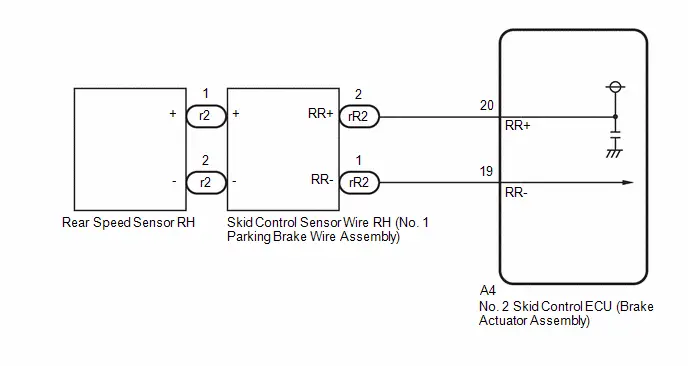
PROCEDURE
| 1. | CHECK Toyota Prius Vehicle |
| Result | Proceed to |
|---|---|
| for 2WD | A |
| for AWD | B |
| B |

| GO TO STEP 6 |
|

| 2. | CHECK HARNESS AND CONNECTOR (SENSOR GROUND CIRCUIT) |
Procedure1
(a) Make sure that there is no looseness at the locking part and the connecting part of the connectors.
OK:
The connector is securely connected.
Pre-procedure1
(b) Disconnect the r2 rear speed sensor RH (rear axle hub and bearing assembly RH) connector.
Procedure2
(c) Check both the connector case and the terminals for deformation and corrosion.
OK:
No deformation or corrosion.
Pre-procedure2
(d) Turn the ignition switch to ON.
Procedure3
(e) Measure the voltage according to the value(s) in the table below.
Standard Voltage:
 Click Location & Routing(r2) Click Connector(r2)
 | Tester Connection | Condition | Specified Condition | Result |
|---|---|---|---|
| r2-2 ( ) - r2-1 (-) | Ignition switch ON | 11 to 14 V | V |
HINT:
The rear speed sensor RH and rear speed sensor rotor RH are incorporated into the rear axle hub and bearing assembly RH.
If the rear speed sensor RH and rear speed sensor rotor RH need to be replaced, replace the rear axle hub and bearing assembly RH.
Post-procedure1
(f) None
| OK |

| REPLACE REAR AXLE HUB AND BEARING ASSEMBLY RH
|


|

| 3. | CHECK HARNESS AND CONNECTOR (SENSOR GROUND CIRCUIT) |
Pre-procedure1
(a) Turn the ignition switch off.
Procedure1
(b) Make sure that there is no looseness at the locking part and the connecting part of the connectors.
OK:
The connector is securely connected.
Pre-procedure2
(c) Disconnect the rR2 skid control sensor wire RH (No. 1 parking brake wire assembly) connector.
Procedure2
(d) Check both the connector case and the terminals for deformation and corrosion.
OK:
No deformation or corrosion.
Pre-procedure3
(e) Turn the ignition switch to ON.
Procedure3
| (f) Measure the voltage according to the value(s) in the table below. Standard Voltage:  Click Location & Routing(rR2) Click Connector(rR2) Click Location & Routing(rR2) Click Connector(rR2)
Result:
|
|
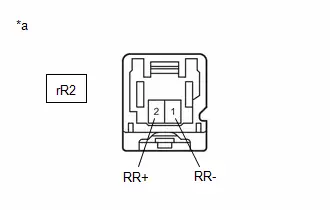
Post-procedure1
(g) None
| OK |

| REPLACE NO. 1 PARKING BRAKE WIRE ASSEMBLY |
|

| 4. | CHECK HARNESS AND CONNECTOR (SENSOR GROUND CIRCUIT) |
Pre-procedure1
(a) Turn the ignition switch off.
Procedure1
(b) Make sure that there is no looseness at the locking part and the connecting part of the connectors.
OK:
The connector is securely connected.
Pre-procedure2
(c) Disconnect the A4 No. 2 skid control ECU (brake actuator assembly) connector.
Procedure2
(d) Check both the connector case and the terminals for deformation and corrosion.
OK:
No deformation or corrosion.
Procedure3
| (e) Measure the voltage according to the value(s) in the table below. Standard Voltage:  Click Location & Routing(rR2) Click Connector(rR2) Click Location & Routing(rR2) Click Connector(rR2)
Result:
|
|
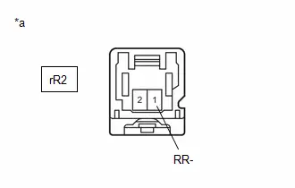
Post-procedure1
(f) None
| NG |

| REPAIR OR REPLACE HARNESS OR CONNECTOR |
|

| 5. | CHECK HARNESS AND CONNECTOR (NO. 1 PARKING BRAKE WIRE ASSEMBLY - BRAKE ACTUATOR ASSEMBLY) |
(a) Measure the resistance according to the value(s) in the table below.
Standard Resistance:
 Click Location & Routing(rR2,A4) Click Connector(rR2) Click Connector(A4)
 | Tester Connection | Condition | Specified Condition | Result |
|---|---|---|---|
| rR2-2 (RR ) or A4-20 (RR ) - rR2-1 (RR-) or A4-19 (RR-) | Always | 10 kΩ or higher | kΩ |
| OK |

| REPLACE BRAKE ACTUATOR ASSEMBLY
|


| NG |

| REPAIR OR REPLACE HARNESS OR CONNECTOR |
| 6. | CHECK HARNESS AND CONNECTOR (SENSOR GROUND CIRCUIT) |
Procedure1
(a) Make sure that there is no looseness at the locking part and the connecting part of the connectors.
OK:
The connector is securely connected.
Pre-procedure1
(b) Disconnect the r2 rear speed sensor RH connector.
Procedure2
(c) Check both the connector case and the terminals for deformation and corrosion.
OK:
No deformation or corrosion.
Pre-procedure2
(d) Turn the ignition switch to ON.
Procedure3
(e) Measure the voltage according to the value(s) in the table below.
Standard Voltage:
 Click Location & Routing(r2) Click Connector(r2)
 | Tester Connection | Condition | Specified Condition | Result |
|---|---|---|---|
| r2-1 ( ) - r2-2 (-) | Ignition switch ON | 11 to 14 V | V |
Post-procedure1
(f) None
| OK |

| REPLACE REAR SPEED SENSOR RH |
|

| 7. | CHECK HARNESS AND CONNECTOR (SENSOR GROUND CIRCUIT) |
Pre-procedure1
(a) Turn the ignition switch off.
Procedure1
(b) Make sure that there is no looseness at the locking part and the connecting part of the connectors.
OK:
The connector is securely connected.
Pre-procedure2
(c) Disconnect the rR2 skid control sensor wire RH (No. 1 parking brake wire assembly) connector.
Procedure2
(d) Check both the connector case and the terminals for deformation and corrosion.
OK:
No deformation or corrosion.
Pre-procedure3
(e) Turn the ignition switch to ON.
Procedure3
| (f) Measure the voltage according to the value(s) in the table below. Standard Voltage:  Click Location & Routing(rR2) Click Connector(rR2) Click Location & Routing(rR2) Click Connector(rR2)
Result:
|
|

Post-procedure1
(g) None
| OK |

| REPLACE NO. 1 PARKING BRAKE WIRE ASSEMBLY |
|

| 8. | CHECK HARNESS AND CONNECTOR (SENSOR GROUND CIRCUIT) |
Pre-procedure1
(a) Turn the ignition switch off.
Procedure1
(b) Make sure that there is no looseness at the locking part and the connecting part of the connectors.
OK:
The connector is securely connected.
Pre-procedure2
(c) Disconnect the A4 No. 2 skid control ECU (brake actuator assembly) connector.
Procedure2
(d) Check both the connector case and the terminals for deformation and corrosion.
OK:
No deformation or corrosion.
Procedure3
| (e) Measure the voltage according to the value(s) in the table below. Standard Voltage:  Click Location & Routing(rR2) Click Connector(rR2) Click Location & Routing(rR2) Click Connector(rR2)
Result:
|
|

Post-procedure1
(f) None
| NG |

| REPAIR OR REPLACE HARNESS OR CONNECTOR |
|

| 9. | CHECK HARNESS AND CONNECTOR (NO. 1 PARKING BRAKE WIRE ASSEMBLY - BRAKE ACTUATOR ASSEMBLY) |
(a) Measure the resistance according to the value(s) in the table below.
Standard Resistance:
 Click Location & Routing(rR2,A4) Click Connector(rR2) Click Connector(A4)
 | Tester Connection | Condition | Specified Condition | Result |
|---|---|---|---|
| rR2-2 (RR ) or A4-20 (RR ) - rR2-1 (RR-) or A4-19 (RR-) | Always | 10 kΩ or higher | kΩ |
| OK |

| REPLACE BRAKE ACTUATOR ASSEMBLY
|


| NG |

| REPAIR OR REPLACE HARNESS OR CONNECTOR |
Right Rear Wheel Speed Sensor Circuit Short to Ground or Open (C051214)
DESCRIPTION
Refer to DTC C051212.
Click here

| DTC No. | Detection Item | DTC Detection Condition | Trouble Area | MIL | DTC Output from | Priority | Note |
|---|---|---|---|---|---|---|---|
| C051214 | Right Rear Wheel Speed Sensor Circuit Short to Ground or Open | An open in the speed sensor signal circuit continues for 0.5 seconds or more. |
| Comes on | Brake/EPB | A |
|
- *1: for AWD
- *2: for 2WD
MONITOR DESCRIPTION
The No. 2 skid control ECU (brake actuator assembly) monitors the output of the speed sensor. When the output current of the speed sensor is excessively low, the MIL is illuminated and a DTC is stored.
MONITOR STRATEGY
| Related DTCs | C0514: Wheel speed sensor (RR) voltage circuit open |
| Required Sensors/Components(Main) | Speed sensor |
| Required Sensors/Components(Related) | No. 2 skid control ECU (brake actuator assembly) |
| Frequency of Operation | Continuous |
| Duration | 0.528 seconds |
| MIL Operation | Immediately |
| Sequence of Operation | None |
TYPICAL ENABLING CONDITIONS
| Monitor runs whenever the following DTCs are not stored | C0501 (Case 1): Wheel speed sensor (FL) range/performance (correlation A) C0501 (Case 2): Wheel speed sensor (FL) range/performance (2 wheels) C0501 (Case 3): Wheel speed sensor (FL) range/performance (correlation B) C0501 (Case 4): Wheel speed sensor (FL) range/performance (pulse output high) C0503: Wheel speed sensor (FL) voltage circuit high C0507 (Case 1): Wheel speed sensor (FR) range/performance (correlation A) C0507 (Case 2): Wheel speed sensor (FR) range/performance (2 wheels) C0507 (Case 3): Wheel speed sensor (FR) range/performance (correlation B) C0507 (Case 4): Wheel speed sensor (FR) range/performance (pulse output high) C0509: Wheel speed sensor (FR) voltage circuit high C050D (Case 1): Wheel speed sensor (RL) range/performance (correlation A) C050D (Case 2): Wheel speed sensor (RL) range/performance (2 wheels) C050D (Case 3): Wheel speed sensor (RL) range/performance (correlation B) C050D (Case 4): Wheel speed sensor (RL) range/performance (pulse output high) C050F: Wheel speed sensor (RL) voltage circuit high C0513 (Case 1): Wheel speed sensor (RR) range/performance (correlation A) C0513 (Case 2): Wheel speed sensor (RR) range/performance (2 wheels) C0513 (Case 3): Wheel speed sensor (RR) range/performance (correlation B) C0513 (Case 4): Wheel speed sensor (RR) range/performance (pulse output high) C0515: Wheel speed sensor (RR) voltage circuit high C137D: Brake system voltage circuit high C14E1 (Case 1): Wheel speed sensor (FL) voltage circuit low C14E1 (Case 2): Wheel speed sensor (FL) voltage circuit low (continuation) C14E4 (Case 1): Wheel speed sensor (FR) voltage circuit low C14E4 (Case 2): Wheel speed sensor (FR) voltage circuit low (continuation) C14E7 (Case 1): Wheel speed sensor (RL) voltage circuit low C14E7 (Case 2): Wheel speed sensor (RL) voltage circuit low (continuation) C14EA (Case 1): Wheel speed sensor (RR) voltage circuit low C14EA (Case 2): Wheel speed sensor (RR) voltage circuit low (continuation) |
| All of the following conditions are met | A, B, C, D, E, F, G and H |
| A. Following condition is met | More than 0.22 seconds |
| BS voltage | 17.4 V or less |
| B. Following condition is met | More than 0.22 seconds |
| BS voltage | 8.5 V or higher |
| C. Command to wheel speed sensor power supply | On |
| D. Following condition is met | More than 0.204 seconds |
| Wheel speed sensor power supply voltage low signal (IC Data) | Off |
| E. Wheel speed sensor overcurrent signal (IC Data) | Off |
| F. BS voltage | 9.5 V or higher |
| G. IGR voltage | Higher than 10 V |
| H. IGP voltage | Higher than 10 V |
TYPICAL MALFUNCTION THRESHOLDS
| Wheel speed sensor open circuit signal (IC Data) | On |
COMPONENT OPERATING RANGE
| Wheel speed sensor open circuit signal (IC Data) | Off |
CONFIRMATION DRIVING PATTERN
NOTICE:
When performing the normal judgment procedure, make sure that the driver door is closed and is not opened at any time during the procedure.
HINT:
- After repair has been completed, clear the DTC and then check that the Toyota Prius vehicle has returned to normal by performing the following All Readiness check procedure.
- When clearing the permanent DTCs, refer to the "CLEAR PERMANENT DTC" procedure.
- Connect the GTS to the DLC3.
- Turn the ignition switch to ON and turn the GTS on.
- Clear the DTCs (even if no DTCs are stored, perform the clear DTC procedure).
- Turn the ignition switch off.
- Turn the ignition switch to ON (READY) and turn the GTS on.
-
Wait for 2 seconds or more. [*]
HINT:
[*]: Normal judgment procedure.
The normal judgment procedure is used to complete DTC judgment and also used when clearing permanent DTCs.
-
Enter the following menus: Chassis / Brake/EPB* / Utility / All Readiness.
*: Electric Parking Brake System
-
Check the DTC judgment result.
HINT:
- If the judgment result shows NORMAL, the system is normal.
- If the judgment result shows ABNORMAL, the system has a malfunction.
- If the judgment result shows INCOMPLETE, perform driving pattern again.
WIRING DIAGRAM
Refer to DTC C051212.
Click here

PROCEDURE
| 1. | READ VALUE USING GTS (MOMENTARY INTERRUPTION) |
Pre-procedure1
(a) Select the line graph display on the GTS.
Procedure1
(b) Check for any momentary interruption in the wire harness and connector.
Chassis > Brake/EPB > Data List| Tester Display | Measurement Item | Range | Normal Condition | Diagnostic Note |
|---|---|---|---|---|
| RR Speed Open | Rear speed sensor RH open detection | Normal / Under intermittent | Normal: Normal Under intermittent: Momentary interruption | - |
| RR Speed Sensor Voltage Open | Rear speed sensor RH voltage open detection | Normal / Under intermittent | Normal: Normal Under intermittent: Momentary interruption | - |
| Tester Display |
|---|
| RR Speed Open |
| RR Speed Sensor Voltage Open |
OK:
Normal (There are no momentary interruptions.)
NOTICE:
Perform the above inspection before removing the sensor and connector.
Post-procedure1
(c) None
| OK |

| USE SIMULATION METHOD TO CHECK |
|

| 2. | CHECK Toyota Prius Vehicle |
| Result | Proceed to |
|---|---|
| for 2WD | A |
| for AWD | B |
| B |

| GO TO STEP 6 |
|

| 3. | INSPECT NO. 1 PARKING BRAKE WIRE ASSEMBLY |
Pre-procedure1
(a) Turn the ignition switch off.
Procedure1
(b) Make sure that there is no looseness at the locking part and the connecting part of the connectors.
OK:
The connector is securely connected.
Pre-procedure2
(c) Disconnect the r2 and rR2 skid control sensor wire RH (No. 1 parking brake wire assembly) connector.
Procedure2
(d) Check both the connector case and the terminals for deformation and corrosion.
OK:
No deformation or corrosion.
Procedure3
| (e) Measure the resistance according to the value(s) in the table below. Standard Resistance:  Click Location & Routing(r2,rR2) Click Connector(r2) Click Connector(rR2) Click Location & Routing(r2,rR2) Click Connector(r2) Click Connector(rR2)
Result:
|
|
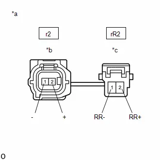
Post-procedure1
(f) None
| NG |

| REPLACE NO. 1 PARKING BRAKE WIRE ASSEMBLY |
|

| 4. | CHECK HARNESS AND CONNECTOR (NO. 1 PARKING BRAKE WIRE ASSEMBLY - BRAKE ACTUATOR ASSEMBLY) |
Procedure1
(a) Make sure that there is no looseness at the locking part and the connecting part of the connectors.
OK:
The connector is securely connected.
Pre-procedure1
(b) Disconnect the A4 No. 2 skid control ECU (brake actuator assembly) connector.
Procedure2
(c) Check both the connector case and the terminals for deformation and corrosion.
OK:
No deformation or corrosion.
Procedure3
(d) Measure the resistance according to the value(s) in the table below.
Standard Resistance:
 Click Location & Routing(rR2,A4) Click Connector(rR2) Click Connector(A4)
 | Tester Connection | Condition | Specified Condition | Result |
|---|---|---|---|
| rR2-2 (RR ) - A4-20 (RR ) | Always | Below 1 Ω | Ω |
| rR2-2 (RR ) or A4-20 (RR ) - Body ground | Always | 10 kΩ or higher | kΩ |
| rR2-1 (RR-) - A4-19 (RR-) | Always | Below 1 Ω | Ω |
| rR2-1 (RR-) or A4-19 (RR-) - Body ground | Always | 10 kΩ or higher | kΩ |
Post-procedure1
(e) None
| NG |

| REPAIR OR REPLACE HARNESS OR CONNECTOR |
|

| 5. | INSPECT BRAKE ACTUATOR ASSEMBLY (SENSOR POWER SOURCE CIRCUIT) |
Pre-procedure1
(a) Reconnect the A4 No. 2 skid control ECU (brake actuator assembly) connector.
(b) Reconnect the rR2 skid control sensor wire RH (No. 1 parking brake wire assembly) connector.
(c) Turn the ignition switch to ON.
Procedure1
(d) Measure the voltage according to the value(s) in the table below.
Standard Voltage:
 Click Location & Routing(r2) Click Connector(r2)
 | Tester Connection | Condition | Specified Condition | Result |
|---|---|---|---|
| r2-2 ( ) - Body ground | Ignition switch ON | 11 to 14 V | V |
HINT:
The rear speed sensor RH and rear speed sensor rotor RH are incorporated into the rear axle hub and bearing assembly RH.
If the rear speed sensor RH and rear speed sensor rotor RH need to be replaced, replace the rear axle hub and bearing assembly RH.
Post-procedure1
(e) None
| OK |

| REPLACE REAR AXLE HUB AND BEARING ASSEMBLY RH
|


| NG |

| REPLACE BRAKE ACTUATOR ASSEMBLY
|


| 6. | INSPECT NO. 1 PARKING BRAKE WIRE ASSEMBLY |
Pre-procedure1
(a) Turn the ignition switch off.
Procedure1
(b) Make sure that there is no looseness at the locking part and the connecting part of the connectors.
OK:
The connector is securely connected.
Pre-procedure2
(c) Disconnect the r2 and rR2 skid control sensor wire RH (No. 1 parking brake wire assembly) connector.
Procedure2
(d) Check both the connector case and the terminals for deformation and corrosion.
OK:
No deformation or corrosion.
Procedure3
| (e) Measure the resistance according to the value(s) in the table below. Standard Resistance:  Click Location & Routing(r2,rR2) Click Connector(r2) Click Connector(rR2) Click Location & Routing(r2,rR2) Click Connector(r2) Click Connector(rR2)
Result:
|
|

Post-procedure1
(f) None
| NG |

| REPLACE NO. 1 PARKING BRAKE WIRE ASSEMBLY |
|

| 7. | CHECK HARNESS AND CONNECTOR (NO. 1 PARKING BRAKE WIRE ASSEMBLY - BRAKE ACTUATOR ASSEMBLY) |
Procedure1
(a) Make sure that there is no looseness at the locking part and the connecting part of the connectors.
OK:
The connector is securely connected.
Pre-procedure1
(b) Disconnect the A4 No. 2 skid control ECU (brake actuator assembly) connector.
Procedure2
(c) Check both the connector case and the terminals for deformation and corrosion.
OK:
No deformation or corrosion.
Procedure3
(d) Measure the resistance according to the value(s) in the table below.
Standard Resistance:
 Click Location & Routing(rR2,A4) Click Connector(rR2) Click Connector(A4)
 | Tester Connection | Condition | Specified Condition | Result |
|---|---|---|---|
| rR2-2 (RR ) - A4-20 (RR ) | Always | Below 1 Ω | Ω |
| rR2-2 (RR ) or A4-20 (RR ) - Body ground | Always | 10 kΩ or higher | kΩ |
| rR2-1 (RR-) - A4-19 (RR-) | Always | Below 1 Ω | Ω |
| rR2-1 (RR-) or A4-19 (RR-) - Body ground | Always | 10 kΩ or higher | kΩ |
Post-procedure1
(e) None
| NG |

| REPAIR OR REPLACE HARNESS OR CONNECTOR |
|

| 8. | INSPECT BRAKE ACTUATOR ASSEMBLY (SENSOR POWER SOURCE CIRCUIT) |
Pre-procedure1
(a) Reconnect the A4 No. 2 skid control ECU (brake actuator assembly) connector.
(b) Reconnect the rR2 skid control sensor wire RH (No. 1 parking brake wire assembly) connector.
(c) Turn the ignition switch to ON.
Procedure1
(d) Measure the voltage according to the value(s) in the table below.
Standard Voltage:
 Click Location & Routing(r2) Click Connector(r2)
 | Tester Connection | Condition | Specified Condition | Result |
|---|---|---|---|
| r2-1 ( ) - Body ground | Ignition switch ON | 11 to 14 V | V |
Post-procedure1
(e) None
| OK |

| REPLACE REAR SPEED SENSOR RH |
| NG |

| REPLACE BRAKE ACTUATOR ASSEMBLY
|


Right Rear Wheel Speed Sensor Circuit Intermittent (C05121F)
DESCRIPTION
Refer to DTC C051212.
Click here

| DTC No. | Detection Item | DTC Detection Condition | Trouble Area | MIL | DTC Output from | Priority | Note |
|---|---|---|---|---|---|---|---|
| C05121F | Right Rear Wheel Speed Sensor Circuit Intermittent | Any of the following is detected:
|
| Comes on | Brake/EPB | A |
|
- *1: for AWD
- *2: for 2WD
MONITOR DESCRIPTION
The No. 2 skid control ECU (brake actuator assembly) monitors the output value of the speed sensors. When the Toyota Prius vehicle is being driven and a sudden irregular change in acceleration due to iron particles being attached to the speed sensor is detected repeatedly, or periodic sudden changes in acceleration due to iron particles being attached to the speed sensor rotor is detected, the No. 2 skid control ECU (brake actuator assembly) judges that speed sensor noise is occurring and illuminates the MIL and stores this DTC.
Also, when the Toyota Prius vehicle is being driven and the output value of the speed sensor is momentarily interrupted repeatedly, the No. 2 skid control ECU (brake actuator assembly) judges that there is a momentary interruption in the speed sensor circuit and illuminates the MIL and stores this DTC.
MONITOR STRATEGY
| Related DTCs | C0516 (Case 1): Wheel speed sensor (RR) intermittent/erratic (moment open) C0516 (Case 2): Wheel speed sensor (RR) intermittent/erratic (a piece of metal noise) C0516 (Case 3): Wheel speed sensor (RR) intermittent/erratic (a piece of metal rotor noise) |
| Required Sensors/Components(Main) | Speed sensor Speed sensor rotor |
| Required Sensors/Components(Related) | - |
| Frequency of Operation | Continuous |
| Duration | 15 seconds: C0516 (Case 3) 0.255 seconds: C0516 (Case 1) 0.075 seconds: C0516 (Case 2) |
| MIL Operation | Immediately |
| Sequence of Operation | None |
TYPICAL ENABLING CONDITIONS
Case 1| Monitor runs whenever the following DTCs are not stored | C0501 (Case 1): Wheel speed sensor (FL) range/performance (correlation A) C0501 (Case 2): Wheel speed sensor (FL) range/performance (2 wheels) C0501 (Case 3): Wheel speed sensor (FL) range/performance (correlation B) C0501 (Case 4): Wheel speed sensor (FL) range/performance (pulse output high) C0502: Wheel speed sensor (FL) voltage circuit open C0503: Wheel speed sensor (FL) voltage circuit high C0507 (Case 1): Wheel speed sensor (FR) range/performance (correlation A) C0507 (Case 2): Wheel speed sensor (FR) range/performance (2 wheels) C0507 (Case 3): Wheel speed sensor (FR) range/performance (correlation B) C0507 (Case 4): Wheel speed sensor (FR) range/performance (pulse output high) C0508: Wheel speed sensor (FR) voltage circuit open C0509: Wheel speed sensor (FR) voltage circuit high C050D (Case 1): Wheel speed sensor (RL) range/performance (correlation A) C050D (Case 2): Wheel speed sensor (RL) range/performance (2 wheels) C050D (Case 3): Wheel speed sensor (RL) range/performance (correlation B) C050D (Case 4): Wheel speed sensor (RL) range/performance (pulse output high) C050E: Wheel speed sensor (RL) voltage circuit open C050F: Wheel speed sensor (RL) voltage circuit high C0513 (Case 1): Wheel speed sensor (RR) range/performance (correlation A) C0513 (Case 2): Wheel speed sensor (RR) range/performance (2 wheels) C0513 (Case 3): Wheel speed sensor (RR) range/performance (correlation B) C0513 (Case 4): Wheel speed sensor (RR) range/performance (pulse output high) C0514: Wheel speed sensor (RR) voltage circuit open C0515: Wheel speed sensor (RR) voltage circuit high C0555: Wheel speed sensor (FL) range/performance C0556: Wheel speed sensor (FR) range/performance C0557: Wheel speed sensor (RL) range/performance C0558: Wheel speed sensor (RR) range/performance C137D: Brake system voltage circuit high C14E1 (Case 1): Wheel speed sensor (FL) voltage circuit low C14E1 (Case 2): Wheel speed sensor (FL) voltage circuit low (continuation) C14E4 (Case 1): Wheel speed sensor (FR) voltage circuit low C14E4 (Case 2): Wheel speed sensor (FR) voltage circuit low (continuation) C14E7 (Case 1): Wheel speed sensor (RL) voltage circuit low C14E7 (Case 2): Wheel speed sensor (RL) voltage circuit low (continuation) C14EA (Case 1): Wheel speed sensor (RR) voltage circuit low C14EA (Case 2): Wheel speed sensor (RR) voltage circuit low (continuation) |
| All of the following conditions are met | A, B and C |
| A. Chassis dynamometer mode | Off |
| B. Following condition is met | More than 0.012 seconds |
| IGR voltage | 3.5 V or higher |
| C. Following condition is met | More than 0.22 seconds |
| BS voltage | 17.4 V or less |
| Monitor runs whenever the following DTCs are not stored | C0501 (Case 1): Wheel speed sensor (FL) range/performance (correlation A) C0501 (Case 2): Wheel speed sensor (FL) range/performance (2 wheels) C0501 (Case 3): Wheel speed sensor (FL) range/performance (correlation B) C0501 (Case 4): Wheel speed sensor (FL) range/performance (pulse output high) C0502: Wheel speed sensor (FL) voltage circuit open C0503: Wheel speed sensor (FL) voltage circuit high C0507 (Case 1): Wheel speed sensor (FR) range/performance (correlation A) C0507 (Case 2): Wheel speed sensor (FR) range/performance (2 wheels) C0507 (Case 3): Wheel speed sensor (FR) range/performance (correlation B) C0507 (Case 4): Wheel speed sensor (FR) range/performance (pulse output high) C0508: Wheel speed sensor (FR) voltage circuit open C0509: Wheel speed sensor (FR) voltage circuit high C050D (Case 1): Wheel speed sensor (RL) range/performance (correlation A) C050D (Case 2): Wheel speed sensor (RL) range/performance (2 wheels) C050D (Case 3): Wheel speed sensor (RL) range/performance (correlation B) C050D (Case 4): Wheel speed sensor (RL) range/performance (pulse output high) C050E: Wheel speed sensor (RL) voltage circuit open C050F: Wheel speed sensor (RL) voltage circuit high C0513 (Case 1): Wheel speed sensor (RR) range/performance (correlation A) C0513 (Case 2): Wheel speed sensor (RR) range/performance (2 wheels) C0513 (Case 3): Wheel speed sensor (RR) range/performance (correlation B) C0513 (Case 4): Wheel speed sensor (RR) range/performance (pulse output high) C0514: Wheel speed sensor (RR) voltage circuit open C0515: Wheel speed sensor (RR) voltage circuit high C0555: Wheel speed sensor (FL) range/performance C0556: Wheel speed sensor (FR) range/performance C0557: Wheel speed sensor (RL) range/performance C0558: Wheel speed sensor (RR) range/performance C137D: Brake system voltage circuit high C14E1 (Case 1): Wheel speed sensor (FL) voltage circuit low C14E1 (Case 2): Wheel speed sensor (FL) voltage circuit low (continuation) C14E4 (Case 1): Wheel speed sensor (FR) voltage circuit low C14E4 (Case 2): Wheel speed sensor (FR) voltage circuit low (continuation) C14E7 (Case 1): Wheel speed sensor (RL) voltage circuit low C14E7 (Case 2): Wheel speed sensor (RL) voltage circuit low (continuation) C14EA (Case 1): Wheel speed sensor (RR) voltage circuit low C14EA (Case 2): Wheel speed sensor (RR) voltage circuit low (continuation) |
| All of the following conditions are met | A, B, C and D |
| A. Chassis dynamometer mode | Off |
| B. Command to all ABS hold solenoids | Off |
| C. Command to all ABS release solenoids | Off |
| D. Following condition is met | More than 0.22 seconds |
| BS voltage | 17.4 V or less |
| Monitor runs whenever the following DTCs are not stored | C0501 (Case 1): Wheel speed sensor (FL) range/performance (correlation A) C0501 (Case 2): Wheel speed sensor (FL) range/performance (2 wheels) C0501 (Case 3): Wheel speed sensor (FL) range/performance (correlation B) C0501 (Case 4): Wheel speed sensor (FL) range/performance (pulse output high) C0502: Wheel speed sensor (FL) voltage circuit open C0503: Wheel speed sensor (FL) voltage circuit high C0507 (Case 1): Wheel speed sensor (FR) range/performance (correlation A) C0507 (Case 2): Wheel speed sensor (FR) range/performance (2 wheels) C0507 (Case 3): Wheel speed sensor (FR) range/performance (correlation B) C0507 (Case 4): Wheel speed sensor (FR) range/performance (pulse output high) C0508: Wheel speed sensor (FR) voltage circuit open C0509: Wheel speed sensor (FR) voltage circuit high C050D (Case 1): Wheel speed sensor (RL) range/performance (correlation A) C050D (Case 2): Wheel speed sensor (RL) range/performance (2 wheels) C050D (Case 3): Wheel speed sensor (RL) range/performance (correlation B) C050D (Case 4): Wheel speed sensor (RL) range/performance (pulse output high) C050E: Wheel speed sensor (RL) voltage circuit open C050F: Wheel speed sensor (RL) voltage circuit high C0513 (Case 1): Wheel speed sensor (RR) range/performance (correlation A) C0513 (Case 2): Wheel speed sensor (RR) range/performance (2 wheels) C0513 (Case 3): Wheel speed sensor (RR) range/performance (correlation B) C0513 (Case 4): Wheel speed sensor (RR) range/performance (pulse output high) C0514: Wheel speed sensor (RR) voltage circuit open C0515: Wheel speed sensor (RR) voltage circuit high C0555: Wheel speed sensor (FL) range/performance C0556: Wheel speed sensor (FR) range/performance C0557: Wheel speed sensor (RL) range/performance C0558: Wheel speed sensor (RR) range/performance C137D: Brake system voltage circuit high C14E1 (Case 1): Wheel speed sensor (FL) voltage circuit low C14E1 (Case 2): Wheel speed sensor (FL) voltage circuit low (continuation) C14E4 (Case 1): Wheel speed sensor (FR) voltage circuit low C14E4 (Case 2): Wheel speed sensor (FR) voltage circuit low (continuation) C14E7 (Case 1): Wheel speed sensor (RL) voltage circuit low C14E7 (Case 2): Wheel speed sensor (RL) voltage circuit low (continuation) C14EA (Case 1): Wheel speed sensor (RR) voltage circuit low C14EA (Case 2): Wheel speed sensor (RR) voltage circuit low (continuation) |
| All of the following conditions are met | A, B, C and D |
| A. Chassis dynamometer mode | Off |
| B. ABS control | Not operating |
| C. Following condition is met | More than 0.012 seconds |
| IGR voltage | 3.5 V or higher |
| C. Following condition is met | More than 0.22 seconds |
| BS voltage | 17.4 V or less |
| D. Toyota Prius Vehicle speed | 10 km/h (6.21 mph) or more |
TYPICAL MALFUNCTION THRESHOLDS
Case 1| Wheel speed sensor status changes from not moment open status to moment open status | Moment open status |
| Wheel speed fluctuation | 502.10048 m/s2 or more |
| Toyota Prius Vehicle speed | 15 km/h (9.32 mph) or more |
| Both of the following conditions A and B are met | 5 seconds or more |
| A. Toyota Prius Vehicle speed | 20 km/h (12.43 mph) or more |
| B. Normal piece of metal noise status | - |
| Wheel speed fluctuation | 502.10048 m/s2 or more experience |
| Adhesion of a piece of metal rotor (noise input at a rotor rotation) | 1 time |
| Noise | 98.0665 m/s2 or more |
COMPONENT OPERATING RANGE
All| All of the following conditions are met | - |
| Chassis dynamometer mode | Off |
| Noise recovery experience | On |
| A piece of metal rotor noise recovery experience | On |
| Low speed recovery experience | On |
CONFIRMATION DRIVING PATTERN
NOTICE:
When performing the normal judgment procedure, make sure that the driver door is closed and is not opened at any time during the procedure.
HINT:
- After repair has been completed, clear the DTC and then check that the Toyota Prius vehicle has returned to normal by performing the following All Readiness check procedure.
- When clearing the permanent DTCs, refer to the "CLEAR PERMANENT DTC" procedure.
- Connect the GTS to the DLC3.
- Turn the ignition switch to ON and turn the GTS on.
- Clear the DTCs (even if no DTCs are stored, perform the clear DTC procedure).
- Turn the ignition switch off.
- Turn the ignition switch to ON (READY) and turn the GTS on.
-
Drive the Toyota Prius vehicle straight at a speed of 20 km/h (12 mph) or more for 15 seconds or more. [*]
HINT:
[*]: Normal judgment procedure.
The normal judgment procedure is used to complete DTC judgment and also used when clearing permanent DTCs.
-
Enter the following menus: Chassis / Brake/EPB* / Utility / All Readiness.
*: Electric Parking Brake System
-
Check the DTC judgment result.
HINT:
- If the judgment result shows NORMAL, the system is normal.
- If the judgment result shows ABNORMAL, the system has a malfunction.
- If the judgment result shows INCOMPLETE, perform driving pattern again.
PROCEDURE
| 1. | CHECK Toyota Prius Vehicle |
| Result | Proceed to |
|---|---|
| for 2WD | A |
| for AWD | B |
| B |

| GO TO STEP 3 |
|

| 2. | READ VALUE USING GTS (RR WHEEL SPEED AND MOMENTARY INTERRUPTION) |
(a) While monitoring the values of the Data List, perform a road test and attempt to reproduce the problem symptoms based on the interview with the customer and the Toyota Prius vehicle conditions stored as Freeze Frame Data when the DTC was stored.
Chassis > Brake/EPB > Data List| Tester Display | Measurement Item | Range | Normal Condition | Diagnostic Note |
|---|---|---|---|---|
| RR Wheel Speed | Rear wheel speed sensor RH reading | Min.: 0.0 km/h (0 mph) Max.: 6553.5 km/h (4072 mph) | Toyota Prius Vehicle stopped: 0.0 km/h (0 mph) | When driving at constant speed: No large fluctuations |
| RR Speed Open | Rear speed sensor RH open detection | Normal / Under intermittent | Normal: Normal Under intermittent: Momentary interruption | - |
| Tester Display |
|---|
| RR Wheel Speed |
| RR Speed Open |
OK:
The values change in accordance with the operation of the Toyota Prius vehicle and there is no intermittent operation.
NOTICE:
Perform the above inspection before removing the sensor and connector.
HINT:
The rear speed sensor RH and rear speed sensor rotor RH are incorporated into the rear axle hub and bearing assembly RH.
If the rear speed sensor RH and rear speed sensor rotor RH need to be replaced, replace the rear axle hub and bearing assembly RH.
| OK |

| USE SIMULATION METHOD TO CHECK |
| NG |

| REPLACE REAR AXLE HUB AND BEARING ASSEMBLY RH
|


| 3. | READ VALUE USING GTS (RR WHEEL SPEED AND MOMENTARY INTERRUPTION) |
(a) While monitoring the values of the Data List, perform a road test and attempt to reproduce the problem symptoms based on the interview with the customer and the Toyota Prius vehicle conditions stored as Freeze Frame Data when the DTC was stored.
Chassis > Brake/EPB > Data List| Tester Display | Measurement Item | Range | Normal Condition | Diagnostic Note |
|---|---|---|---|---|
| RR Wheel Speed | Rear wheel speed sensor RH reading | Min.: 0.0 km/h (0 mph) Max.: 6553.5 km/h (4072 mph) | Toyota Prius Vehicle stopped: 0.0 km/h (0 mph) | When driving at constant speed: No large fluctuations |
| RR Speed Open | Rear speed sensor RH open detection | Normal / Under intermittent | Normal: Normal Under intermittent: Momentary interruption | - |
| Tester Display |
|---|
| RR Wheel Speed |
| RR Speed Open |
OK:
The values change in accordance with the operation of the Toyota Prius vehicle and there is no intermittent operation.
NOTICE:
Perform the above inspection before removing the sensor and connector.
| OK |

| USE SIMULATION METHOD TO CHECK |
|

| 4. | CHECK REAR SPEED SENSOR RH INSTALLATION |
Pre-procedure1
(a) Turn the ignition switch off.
Procedure1
| (b) Check the rear speed sensor RH installation. OK: There is no clearance between the rear speed sensor RH and the rear axle hub and bearing assembly RH. The installation bolt is tightened properly. Result:
|
|

Post-procedure1
(c) None
| NG |

| REINSTALL OR REPLACE REAR SPEED SENSOR RH |
|

| 5. | CHECK REAR SPEED SENSOR RH (CHECK FOR FOREIGN MATTER) |
(a) Remove the rear speed sensor RH, and confirm that there is no foreign matter, oil or grease on the rear speed sensor tip RH.
OK:
The rear speed sensor tip RH is free of oil and foreign matter.
HINT:
If foreign matter of 1 mm (0.03937 in.) x 1 mm (0.03937 in.) or more is adhered to the rear speed sensor RH, this DTC may be stored.
| NG |

| GO TO STEP 9 |
|

| 6. | CHECK REAR SPEED SENSOR ROTOR RH (CHECK FOR FOREIGN MATTER) |
(a) Confirm that there is no foreign matter, oil or grease on the rear speed sensor rotor RH.
OK:
The rear speed sensor rotor RH is free of oil and foreign matter.
HINT:
- If foreign matter of 1 mm (0.03937 in.) x 1 mm (0.03937 in.) or more is adhered to the rear speed sensor rotor RH, this DTC may be stored.
-
The rear speed sensor rotor RH is incorporated into the rear axle hub and bearing assembly RH.
If the rear speed sensor rotor RH needs to be replaced, replace it together with the rear axle hub and bearing assembly RH.
| OK |

| REPLACE REAR SPEED SENSOR RH AND REAR SPEED SENSOR ROTOR RH for Rear Speed Sensor RH: Click here
for Rear Speed Sensor Rotor RH: Click here
|


|

| 7. | CLEAN REAR SPEED SENSOR ROTOR RH |
(a) Clean the rear speed sensor rotor RH.
NOTICE:
Do not use parts cleaner when cleaning the rear speed sensor rotor RH.
|

| 8. | READ VALUE USING GTS (RR WHEEL SPEED AND MOMENTARY INTERRUPTION) |
(a) While monitoring the values of the Data List, perform a road test and attempt to reproduce the problem symptoms based on the interview with the customer and the Toyota Prius vehicle conditions stored as Freeze Frame Data when the DTC was stored.
Chassis > Brake/EPB > Data List| Tester Display | Measurement Item | Range | Normal Condition | Diagnostic Note |
|---|---|---|---|---|
| RR Wheel Speed | Rear wheel speed sensor RH reading | Min.: 0.0 km/h (0 mph) Max.: 6553.5 km/h (4072 mph) | Toyota Prius Vehicle stopped: 0.0 km/h (0 mph) | When driving at constant speed: No large fluctuations |
| RR Speed Open | Rear speed sensor RH open detection | Normal / Under intermittent | Normal: Normal Under intermittent: Momentary interruption | - |
| Tester Display |
|---|
| RR Wheel Speed |
| RR Speed Open |
OK:
The values change in accordance with the operation of the Toyota Prius vehicle and there is no intermittent operation.
NOTICE:
Perform the above inspection before removing the sensor and connector.
HINT:
The rear speed sensor rotor RH is incorporated into the rear axle hub and bearing assembly RH.
If the rear speed sensor rotor RH needs to be replaced, replace it together with the rear axle hub and bearing assembly RH.
| OK |

| END |
| NG |

| REPLACE REAR SPEED SENSOR RH AND REAR SPEED SENSOR ROTOR RH for Rear Speed Sensor RH: Click here
for Rear Speed Sensor Rotor RH: Click here
|


| 9. | CLEAN REAR SPEED SENSOR RH |
(a) Clean the rear speed sensor RH.
NOTICE:
When cleaning the rear speed sensor RH, make sure to clean the installation hole before installation.
|

| 10. | READ VALUE USING GTS (RR WHEEL SPEED AND MOMENTARY INTERRUPTION) |
(a) While monitoring the values of the Data List, perform a road test and attempt to reproduce the problem symptoms based on the interview with the customer and the Toyota Prius vehicle conditions stored as Freeze Frame Data when the DTC was stored.
Chassis > Brake/EPB > Data List| Tester Display | Measurement Item | Range | Normal Condition | Diagnostic Note |
|---|---|---|---|---|
| RR Wheel Speed | Rear wheel speed sensor RH reading | Min.: 0.0 km/h (0 mph) Max.: 6553.5 km/h (4072 mph) | Toyota Prius Vehicle stopped: 0.0 km/h (0 mph) | When driving at constant speed: No large fluctuations |
| RR Speed Open | Rear speed sensor RH open detection | Normal / Under intermittent | Normal: Normal Under intermittent: Momentary interruption | - |
| Tester Display |
|---|
| RR Wheel Speed |
| RR Speed Open |
OK:
The values change in accordance with the operation of the Toyota Prius vehicle and there is no intermittent operation.
NOTICE:
Perform the above inspection before removing the sensor and connector.
| OK |

| END |
| NG |

| GO TO STEP 6 |
Right Rear Wheel Speed Sensor Signal Stuck Low (C051223)
DESCRIPTION
Refer to DTC C051212.
Click here

| DTC No. | Detection Item | DTC Detection Condition | Trouble Area | MIL | DTC Output from | Priority | Note |
|---|---|---|---|---|---|---|---|
| C051223 | Right Rear Wheel Speed Sensor Signal Stuck Low | Any of the following is detected:
|
| Comes on | Brake/EPB | A |
|
- *1: for AWD
- *2: for 2WD
MONITOR DESCRIPTION
-
When the Toyota Prius vehicle is being driven, if the value of the speed sensor which is outputting the lowest vehicle speed is significantly lower than the values of the other speed sensors, or the value of the speed sensor which is outputting the lowest vehicle speed is 0 km/h (0 mph), the No. 2 skid control ECU (brake actuator assembly) judges that the speed sensor is malfunctioning and illuminates the MIL and stores this DTC.
Also, when a wheel speed is being output (the wheel is not locked), if the output values of the speed sensors for 2 wheels are stuck at 0 km/h (0 mph), the No. 2 skid control ECU (brake actuator assembly) judges that a speed sensor is malfunctioning and illuminates the MIL and stores this DTC.
- When the Toyota Prius vehicle is being driven at a certain speed or more, the rotational direction of 3 wheels is determined, and the rotational direction of 1 wheel is not determined for a certain amount of time, the No. 2 skid control ECU (brake actuator assembly) judges that the speed sensor is malfunctioning and illuminates the MIL and stores this DTC.
MONITOR STRATEGY
| Related DTCs | C0513 (Case 1): Wheel speed sensor (RR) range/performance (correlation A) C0513 (Case 2): Wheel speed sensor (RR) range/performance (2 wheels) C0513 (Case 3): Wheel speed sensor (RR) range/performance (correlation B) C0513 (Case 5): Wheel speed sensor (RR) range/performance (rotatory direction) |
| Required Sensors/Components(Main) | Speed sensor Speed sensor rotor |
| Required Sensors/Components(Related) | No. 2 skid control ECU (brake actuator assembly) Stop light switch assembly Speed sensor |
| Frequency of Operation | Continuous |
| Duration | 1 second: C0513 (Case 3) 3 seconds: C0513 (Case 5) 30 seconds: C0513 (Case 1 and 2) |
| MIL Operation | Immediately |
| Sequence of Operation | None |
TYPICAL ENABLING CONDITIONS
Case 1| Monitor runs whenever the following DTCs are not stored | C0501 (Case 2): Wheel speed sensor (FL) range/performance (2 wheels) C0501 (Case 4): Wheel speed sensor (FL) range/performance (pulse output high) C0502: Wheel speed sensor (FL) voltage circuit open C0503: Wheel speed sensor (FL) voltage circuit high C0504 (Case 1): Wheel speed sensor (FL) intermittent/erratic (moment open) C0504 (Case 2): Wheel speed sensor (FL) intermittent/erratic (a piece of metal noise) C0504 (Case 3): Wheel speed sensor (FL) intermittent/erratic (a piece of metal rotor noise) C0507 (Case 2): Wheel speed sensor (FR) range/performance (2 wheels) C0507 (Case 4): Wheel speed sensor (FR) range/performance (pulse output high) C0508: Wheel speed sensor (FR) voltage circuit open C0509: Wheel speed sensor (FR) voltage circuit high C050A (Case 1): Wheel speed sensor (FR) intermittent/erratic (moment open) C050A (Case 2): Wheel speed sensor (FR) intermittent/erratic (a piece of metal noise) C050A (Case 3): Wheel speed sensor (FR) intermittent/erratic (a piece of metal rotor noise) C050D (Case 2): Wheel speed sensor (RL) range/performance (2 wheels) C050D (Case 4): Wheel speed sensor (RL) range/performance (pulse output high) C050E: Wheel speed sensor (RL) voltage circuit open C050F: Wheel speed sensor (RL) voltage circuit high C0510 (Case 1): Wheel speed sensor (RL) intermittent/erratic (moment open) C0510 (Case 2): Wheel speed sensor (RL) intermittent/erratic (a piece of metal noise) C0510 (Case 3): Wheel speed sensor (RL) intermittent/erratic (a piece of metal rotor noise) C0513 (Case 2): Wheel speed sensor (RR) range/performance (2 wheels) C0513 (Case 4): Wheel speed sensor (RR) range/performance (pulse output high) C0514: Wheel speed sensor (RR) voltage circuit open C0515: Wheel speed sensor (RR) voltage circuit high C0516 (Case 1): Wheel speed sensor (RR) intermittent/erratic (moment open) C0516 (Case 2): Wheel speed sensor (RR) intermittent/erratic (a piece of metal noise) C0516 (Case 3): Wheel speed sensor (RR) intermittent/erratic (a piece of metal rotor noise) C137D: Brake system voltage circuit high C14E1 (Case 1): Wheel speed sensor (FL) voltage circuit low C14E1 (Case 2): Wheel speed sensor (FL) voltage circuit low (continuation) C14E4 (Case 1): Wheel speed sensor (FR) voltage circuit low C14E4 (Case 2): Wheel speed sensor (FR) voltage circuit low (continuation) C14E7 (Case 1): Wheel speed sensor (RL) voltage circuit low C14E7 (Case 2): Wheel speed sensor (RL) voltage circuit low (continuation) C14EA (Case 1): Wheel speed sensor (RR) voltage circuit low C14EA (Case 2): Wheel speed sensor (RR) voltage circuit low (continuation) |
| All of the following conditions are met | A, B, C, D, E, F, G and H |
| A. Chassis dynamometer mode | Off |
| B. Following condition is met | More than 0.012 seconds |
| IGR voltage | 3.5 V or higher |
| C. Command to all ABS hold solenoids | Off |
| D. Command to all ABS release solenoids | Off |
| E. Following condition is met | More than 0.22 seconds |
| BS voltage | 17.4 V or less |
| F. Difference between the highest speed sensor output value and the second lowest speed sensor output value | Less than 20% of the highest speed sensor output value |
| G. The second lowest speed sensor output value | 60 Hz 2 km/h (1.24 mph) or more |
| H. IGP voltage | Higher than 10 V |
| Monitor runs whenever the following DTCs are not stored | C0501 (Case 4): Wheel speed sensor (FL) range/performance (pulse output high) C0502: Wheel speed sensor (FL) voltage circuit open C0503: Wheel speed sensor (FL) voltage circuit high C0504 (Case 1): Wheel speed sensor (FL) intermittent/erratic (moment open) C0504 (Case 2): Wheel speed sensor (FL) intermittent/erratic (a piece of metal noise) C0504 (Case 3): Wheel speed sensor (FL) intermittent/erratic (a piece of metal rotor noise) C0507 (Case 4): Wheel speed sensor (FR) range/performance (pulse output high) C0508: Wheel speed sensor (FR) voltage circuit open C0509: Wheel speed sensor (FR) voltage circuit high C050A (Case 1): Wheel speed sensor (FR) intermittent/erratic (moment open) C050A (Case 2): Wheel speed sensor (FR) intermittent/erratic (a piece of metal noise) C050A (Case 3): Wheel speed sensor (FR) intermittent/erratic (a piece of metal rotor noise) C050D (Case 4): Wheel speed sensor (RL) range/performance (pulse output high) C050E: Wheel speed sensor (RL) voltage circuit open C050F: Wheel speed sensor (RL) voltage circuit high C0510 (Case 1): Wheel speed sensor (RL) intermittent/erratic (moment open) C0510 (Case 2): Wheel speed sensor (RL) intermittent/erratic (a piece of metal noise) C0510 (Case 3): Wheel speed sensor (RL) intermittent/erratic (a piece of metal rotor noise) C0513 (Case 4): Wheel speed sensor (RR) range/performance (pulse output high) C0514: Wheel speed sensor (RR) voltage circuit open C0515: Wheel speed sensor (RR) voltage circuit high C0516 (Case 1): Wheel speed sensor (RR) intermittent/erratic (moment open) C0516 (Case 2): Wheel speed sensor (RR) intermittent/erratic (a piece of metal noise) C0516 (Case 3): Wheel speed sensor (RR) intermittent/erratic (a piece of metal rotor noise) C137D: Brake system voltage circuit high C14E1 (Case 1): Wheel speed sensor (FL) voltage circuit low C14E1 (Case 2): Wheel speed sensor (FL) voltage circuit low (continuation) C14E4 (Case 1): Wheel speed sensor (FR) voltage circuit low C14E4 (Case 2): Wheel speed sensor (FR) voltage circuit low (continuation) C14E7 (Case 1): Wheel speed sensor (RL) voltage circuit low C14E7 (Case 2): Wheel speed sensor (RL) voltage circuit low (continuation) C14EA (Case 1): Wheel speed sensor (RR) voltage circuit low C14EA (Case 2): Wheel speed sensor (RR) voltage circuit low (continuation) |
| All of the following conditions are met | A, B, C, D, E, F, G, H and I |
| A. Chassis dynamometer mode | Off |
| B. Following condition is met | More than 0.012 seconds |
| IGR voltage | 3.5 V or higher |
| C. Command to all ABS hold solenoids | Off |
| D. Command to all ABS release solenoids | Off |
| E. Following condition is met | More than 0.22 seconds |
| BS voltage | 17.4 V or less |
| F. Brake pedal operation | Off |
| G. Parking brake | Off |
| H. Difference between the highest speed sensor output value and the second highest speed sensor output value | Less than 20% of the highest speed sensor output value |
| I. The second highest speed sensor output value | 60 Hz 2 km/h (1.24 mph) or more |
| Monitor runs whenever the following DTCs are not stored | C0501 (Case 1): Wheel speed sensor (FL) range/performance (correlation A) C0501 (Case 2): Wheel speed sensor (FL) range/performance (2 wheels) C0501 (Case 3): Wheel speed sensor (FL) range/performance (correlation B) C0501 (Case 4): Wheel speed sensor (FL) range/performance (pulse output high) C0502: Wheel speed sensor (FL) voltage circuit open C0503: Wheel speed sensor (FL) voltage circuit high C0504 (Case 1): Wheel speed sensor (FL) intermittent/erratic (moment open) C0504 (Case 2): Wheel speed sensor (FL) intermittent/erratic (a piece of metal noise) C0504 (Case 3): Wheel speed sensor (FL) intermittent/erratic (a piece of metal rotor noise) C0507 (Case 1): Wheel speed sensor (FR) range/performance (correlation A) C0507 (Case 2): Wheel speed sensor (FR) range/performance (2 wheels) C0507 (Case 3): Wheel speed sensor (FR) range/performance (correlation B) C0507 (Case 4): Wheel speed sensor (FR) range/performance (pulse output high) C0508: Wheel speed sensor (FR) voltage circuit open C0509: Wheel speed sensor (FR) voltage circuit high C0510 (Case 1): Wheel speed sensor (RL) intermittent/erratic (moment open) C0510 (Case 2): Wheel speed sensor (RL) intermittent/erratic (a piece of metal noise) C0510 (Case 3): Wheel speed sensor (RL) intermittent/erratic (a piece of metal rotor noise) C0513 (Case 1): Wheel speed sensor (RR) range/performance (correlation A) C0513 (Case 2): Wheel speed sensor (RR) range/performance (2 wheels) C0513 (Case 4): Wheel speed sensor (RR) range/performance (pulse output high) C0514: Wheel speed sensor (RR) voltage circuit open C0515: Wheel speed sensor (RR) voltage circuit high C0516 (Case 1): Wheel speed sensor (RR) intermittent/erratic (moment open) C0516 (Case 2): Wheel speed sensor (RR) intermittent/erratic (a piece of metal noise) C0516 (Case 3): Wheel speed sensor (RR) intermittent/erratic (a piece of metal rotor noise) C050A (Case 1): Wheel speed sensor (FR) intermittent/erratic (moment open) C050A (Case 2): Wheel speed sensor (FR) intermittent/erratic (a piece of metal noise) C050A (Case 3): Wheel speed sensor (FR) intermittent/erratic (a piece of metal rotor noise) C050D (Case 1): Wheel speed sensor (RL) range/performance (correlation A) C050D (Case 2): Wheel speed sensor (RL) range/performance (2 wheels) C050D (Case 3): Wheel speed sensor (RL) range/performance (correlation B) C050D (Case 4): Wheel speed sensor (RL) range/performance (pulse output high) C050E: Wheel speed sensor (RL) voltage circuit open C050F: Wheel speed sensor (RL) voltage circuit high C051C (Case 1): Acceleration sensor range/Performance (acceleration sensor lock) C051C (Case 2): Acceleration sensor range/Performance (GL1, GL2 lock) C051C (Case 3): Acceleration sensor range/Performance (acceleration sensor output) C051D: Acceleration sensor missing calibration C051E: Acceleration sensor intermittent/erratic C0520 (Case 1): Acceleration sensor (GL1, GL2) out of range C0520 (Case 2): Acceleration sensor GL2 out of range C0520 (Case 3): Acceleration sensor internal check C052B (Case 1 to 7): ABS pump motor performance (gate voltage) C052B (Case 8): ABS pump motor performance (motor relay current) C052B (Case 9): ABS pump motor performance (freewheeling MOS current) C052D: ABS pump motor circuit high C052E (Case 1 to 4): ABS pump motor circuit open (motor circuit) C052E (Case 5 and 6): ABS pump motor circuit open (motor relay) C053D: Master cylinder pressure sensor exceeded learning limit C0540 (Case 1): Pressure sensor lost communication C0540 (Case 2): Pressure sensor internal check C0540 (Case 3): Pressure sensor invalid data C0555: Wheel speed sensor (FL) range/performance C0556: Wheel speed sensor (FR) range/performance C0557: Wheel speed sensor (RL) range/performance C0558: Wheel speed sensor (RR) range/performance C056B: Pressure sensor intermittent/erratic C0597: ABS hold solenoid performance C05C1: Brake pedal position sensor learning not complete C1103 (Case 1): Brake pedal position sensor voltage circuit open C122E: Pressure sensor voltage circuit low C122F: Pressure sensor voltage circuit high C1240: Yaw rate and acceleration sensor incorrect C124A: Identification signal C12A7 (Case 1 and 2): ABS hold solenoid (FL) circuit open C12A7 (Case 3): ABS hold solenoid (FL) circuit low C12A8 (Case 1): ABS hold solenoid (FL) circuit high (solenoid Off current) C12A8 (Case 2 and 3): ABS hold solenoid (FL) circuit high (IC data) C12A8 (Case 4): ABS hold solenoid (FL) circuit high (solenoid On current) C12B2: ABS release solenoid (FL) circuit low C12B3: ABS release solenoid (FL) circuit high C12BD (Case 1 and 2): ABS hold solenoid (FR) circuit open C12BD (Case 3): ABS hold solenoid (FR) circuit low C12BE (Case 1): ABS hold solenoid (FR) circuit high (solenoid Off current) C12BE (Case 2 and 3): ABS hold solenoid (FR) circuit high (IC data) C12BE (Case 4): ABS hold solenoid (FR) circuit high (solenoid On current) C12C8: ABS release solenoid (FR) circuit low C12C9: ABS release solenoid (FR) circuit high C12D3 (Case 1 and 2): ABS hold solenoid (RL) circuit open C12D3 (Case 3): ABS hold solenoid (RL) circuit low C12D4 (Case 1): ABS hold solenoid (RL) circuit high (solenoid Off current) C12D4 (Case 2 and 3): ABS hold solenoid (RL) circuit high (IC data) C12D4 (Case 4): ABS hold solenoid (RL) circuit high (solenoid On current) C12DE: ABS release solenoid (RL) circuit low C12DF: ABS release solenoid (RL) circuit high C12E9 (Case 1 and 2): ABS hold solenoid (RR) circuit open C12E9 (Case 3): ABS hold solenoid (RR) circuit low C12EA (Case 1): ABS hold solenoid (RR) circuit high (solenoid Off current) C12EA (Case 2 and 3): ABS hold solenoid (RR) circuit high (IC data) C12EA (Case 4): ABS hold solenoid (RR) circuit high (solenoid On current) C12F4: ABS release solenoid (RR) circuit low C12F5: ABS release solenoid (RR) circuit high C12F6: ABS hold solenoid other functional C12F7: ABS hold solenoid other functional C13BF: SM solenoid other functional C13C2 (Case 1 and 2): SM1 solenoid circuit open C13C2 (Case 3): SM1 solenoid circuit low C13C3 (Case 1): SM1 solenoid circuit high (solenoid Off current) C13C3 (Case 2 and 3): SM1 solenoid circuit high (IC data) C13C3 (Case 4): SM1 solenoid circuit high (solenoid On current) C13CB (Case 1 and 2): SM2 solenoid circuit open C13CB (Case 3): SM2 solenoid circuit low C13CC (Case 1): SM2 solenoid circuit high (solenoid Off current) C13CC (Case 2 and 3): SM2 solenoid circuit high (IC data) C13CC (Case 4): SM2 solenoid circuit high (solenoid On current) C137D: Brake system voltage circuit high C1427: ABS pump motor stuck C143B: Brake system voltage power supply relay circuit high C143C: Brake system voltage power supply relay circuit open C14E1 (Case 1): Wheel speed sensor (FL) voltage circuit low C14E1 (Case 2): Wheel speed sensor (FL) voltage circuit low (continuation) C14E4 (Case 1): Wheel speed sensor (FR) voltage circuit low C14E4 (Case 2): Wheel speed sensor (FR) voltage circuit low (continuation) C14E7 (Case 1): Wheel speed sensor (RL) voltage circuit low C14E7 (Case 2): Wheel speed sensor (RL) voltage circuit low (continuation) C14EA (Case 1): Wheel speed sensor (RR) voltage circuit low C14EA (Case 2): Wheel speed sensor (RR) voltage circuit low (continuation) P05DB: Brake pedal position sensor invalid data P05DD: Brake pedal position sensor circuit open P05DE: Brake pedal position sensor circuit high P05DF: Brake pedal position sensor intermittent/erratic P05E0: Brake pedal position sensor "A"/"B" correlation U0125: Lost communication with multi-axis acceleration sensor module |
| All of the following conditions are met | A, B, C, D, E, F, G, H and I |
| A. Chassis dynamometer mode | Off |
| B. Following condition is met | More than 0.012 seconds |
| IGR voltage | 3.5 V or higher |
| C. Command to all ABS hold solenoids | Off |
| D. Command to all ABS release solenoids | Off |
| E. Following condition is met | More than 0.22 seconds |
| BS voltage | 17.4 V or less |
| F. Brake pedal operation | Off |
| G. Parking brake | Off |
| H. Difference between the highest speed sensor output value and the second lowest speed sensor output value | Less than 2 km/h (1.24 mph) |
| I. BM voltage | 6 V or higher |
| Monitor runs whenever the following DTCs are not stored | C0501 (Case 4): Wheel speed sensor (FL) range/performance (pulse output high) C0502: Wheel speed sensor (FL) voltage circuit open C0503: Wheel speed sensor (FL) voltage circuit high C0504 (Case 1): Wheel speed sensor (FL) intermittent/erratic (moment open) C0504 (Case 2): Wheel speed sensor (FL) intermittent/erratic (a piece of metal noise) C0504 (Case 3): Wheel speed sensor (FL) intermittent/erratic (a piece of metal rotor noise) C0507 (Case 4): Wheel speed sensor (FR) range/performance (pulse output high) C0508: Wheel speed sensor (FR) voltage circuit open C0509: Wheel speed sensor (FR) voltage circuit high C050A (Case 1): Wheel speed sensor (FR) intermittent/erratic (moment open) C050A (Case 2): Wheel speed sensor (FR) intermittent/erratic (a piece of metal noise) C050A (Case 3): Wheel speed sensor (FR) intermittent/erratic (a piece of metal rotor noise) C050D (Case 4): Wheel speed sensor (RL) range/performance (pulse output high) C050E: Wheel speed sensor (RL) voltage circuit open C050F: Wheel speed sensor (RL) voltage circuit high C0510 (Case 1): Wheel speed sensor (RL) intermittent/erratic (moment open) C0510 (Case 2): Wheel speed sensor (RL) intermittent/erratic (a piece of metal noise) C0510 (Case 3): Wheel speed sensor (RL) intermittent/erratic (a piece of metal rotor noise) C0513 (Case 4): Wheel speed sensor (RR) range/performance (pulse output high) C0514: Wheel speed sensor (RR) voltage circuit open C0515: Wheel speed sensor (RR) voltage circuit high C0516 (Case 1): Wheel speed sensor (RR) intermittent/erratic (moment open) C0516 (Case 2): Wheel speed sensor (RR) intermittent/erratic (a piece of metal noise) C0516 (Case 3): Wheel speed sensor (RR) intermittent/erratic (a piece of metal rotor noise) C137D: Brake system voltage circuit high C14E1 (Case 1): Wheel speed sensor (FL) voltage circuit low C14E1 (Case 2): Wheel speed sensor (FL) voltage circuit low (continuation) C14E4 (Case 1): Wheel speed sensor (FR) voltage circuit low C14E4 (Case 2): Wheel speed sensor (FR) voltage circuit low (continuation) C14E7 (Case 1): Wheel speed sensor (RL) voltage circuit low C14E7 (Case 2): Wheel speed sensor (RL) voltage circuit low (continuation) C14EA (Case 1): Wheel speed sensor (RR) voltage circuit low C14EA (Case 2): Wheel speed sensor (RR) voltage circuit low (continuation) |
| All of the following conditions are met | - |
| Chassis dynamometer mode | Off |
| Command to all ABS hold solenoids | Off |
| Command to all ABS release solenoids | Off |
| Difference between the highest speed sensor output value and the lowest speed sensor output value | Less than 10% of the highest speed sensor output value |
| Lowest speed sensor output value | Higher than 30 km/h (18.64 mph) |
TYPICAL MALFUNCTION THRESHOLDS
Case 1| One-seventh of the second lowest speed sensor output value | Higher than the lowest speed sensor output value |
| Second lowest speed sensor output value | 0 km/h (0 mph) |
| Both of the following conditions are met | - |
| Lowest speed sensor output value | 0 km/h (0 mph) |
| The lowest speed sensor value changes from less than 60 Hz 2 km/h (1.24 mph) to 60 Hz 2 km/h (1.24 mph) or more | - |
| Both of the following conditions are met | - |
| Direction of 3 wheels | Determined |
| Direction of 1 wheel | Undetermined |
COMPONENT OPERATING RANGE
Case 1 to 3| All of the following conditions are met | - |
| Chassis dynamometer mode | Off |
| Wheel speed sensor fail (C0502, C0503, C0508, C0509, C050E, C050F, C0514, C0515) | Not detected |
| Wheel speed sensor voltage circuit low fail (C14E1, C14E4, C14E7, C14EA) | Not detected |
| Noise recovery experience | On |
| A piece of metal rotor noise recovery experience | On |
| Low speed recovery experience | On |
| All of the following conditions are met | - |
| Chassis dynamometer mode | Off |
| Command to all ABS hold solenoids | Off |
| Command to all ABS release solenoids | Off |
| Difference between the highest speed sensor output value and the lowest speed sensor output value | Less than 10% of the highest speed sensor output value |
| Lowest speed sensor output value | Higher than 30 km/h (18.64 mph) |
| Direction of 4 wheels | Determined |
CONFIRMATION DRIVING PATTERN
NOTICE:
When performing the normal judgment procedure, make sure that the driver door is closed and is not opened at any time during the procedure.
HINT:
- After repair has been completed, clear the DTC and then check that the Toyota Prius vehicle has returned to normal by performing the following All Readiness check procedure.
- When clearing the permanent DTCs, refer to the "CLEAR PERMANENT DTC" procedure.
- Connect the GTS to the DLC3.
- Turn the ignition switch to ON and turn the GTS on.
- Clear the DTCs (even if no DTCs are stored, perform the clear DTC procedure).
- Turn the ignition switch off.
- Turn the ignition switch to ON (READY) and turn the GTS on.
-
Drive the Toyota Prius vehicle straight at a speed of 20 km/h (12 mph) or more for 30 seconds or more. [*]
HINT:
[*]: Normal judgment procedure.
The normal judgment procedure is used to complete DTC judgment and also used when clearing permanent DTCs.
-
Enter the following menus: Chassis / Brake/EPB* / Utility / All Readiness.
*: Electric Parking Brake System
-
Check the DTC judgment result.
HINT:
- If the judgment result shows NORMAL, the system is normal.
- If the judgment result shows ABNORMAL, the system has a malfunction.
- If the judgment result shows INCOMPLETE, perform driving pattern again.
WIRING DIAGRAM
Refer to DTC C051212.
Click here

PROCEDURE
| 1. | CHECK Toyota Prius Vehicle |
| Result | Proceed to |
|---|---|
| for 2WD | A |
| for AWD | B |
| B |

| GO TO STEP 6 |
|

| 2. | CHECK REAR SPEED SENSOR RH INSTALLATION |
| (a) Check the rear speed sensor RH installation. OK: There is no clearance between the rear speed sensor RH and the rear axle hub and bearing assembly RH. HINT: The rear speed sensor rotor RH and rear speed sensor RH are incorporated into the rear axle hub and bearing assembly RH. If the rear speed sensor rotor RH needs to be replaced, replace the rear axle hub and bearing assembly RH with rear speed sensor RH. |
|

| NG |

| REPLACE REAR AXLE HUB AND BEARING ASSEMBLY RH
|


|

| 3. | READ VALUE USING GTS (RR WHEEL SPEED) |
Pre-procedure1
(a) Perform a road test.
Procedure1
(b) Check the rear speed sensor RH (rear axle hub and bearing assembly RH) output value.
Chassis > Brake/EPB > Data List| Tester Display | Measurement Item | Range | Normal Condition | Diagnostic Note |
|---|---|---|---|---|
| RR Wheel Speed | Rear wheel speed sensor RH reading | Min.: 0.0 km/h (0 mph) Max.: 6553.5 km/h (4072 mph) | Toyota Prius Vehicle stopped: 0.0 km/h (0 mph) | When driving at constant speed: No large fluctuations |
| Tester Display |
|---|
| RR Wheel Speed |
OK:
The output value changes in accordance with the Toyota Prius vehicle speed.
Post-procedure1
(c) None
| OK |

| USE SIMULATION METHOD TO CHECK |
|

| 4. | INSPECT NO. 1 PARKING BRAKE WIRE ASSEMBLY |
Pre-procedure1
(a) Turn the ignition switch off.
Procedure1
(b) Make sure that there is no looseness at the locking part and the connecting part of the connectors.
OK:
The connector is securely connected.
Pre-procedure2
(c) Disconnect the r2 and rR2 skid control sensor wire RH (No. 1 parking brake wire assembly) connector.
Procedure2
(d) Check both the connector case and the terminals for deformation and corrosion.
OK:
No deformation or corrosion.
Procedure3
| (e) Measure the resistance according to the value(s) in the table below. Standard Resistance:  Click Location & Routing(r2,rR2) Click Connector(r2) Click Connector(rR2) Click Location & Routing(r2,rR2) Click Connector(r2) Click Connector(rR2)
Result:
|
|

Post-procedure1
(f) None
| NG |

| REPLACE NO. 1 PARKING BRAKE WIRE ASSEMBLY |
|

| 5. | CHECK HARNESS AND CONNECTOR (NO. 1 PARKING BRAKE WIRE ASSEMBLY - BRAKE ACTUATOR ASSEMBLY) |
Procedure1
(a) Make sure that there is no looseness at the locking part and the connecting part of the connectors.
OK:
The connector is securely connected.
Pre-procedure1
(b) Disconnect the A4 No. 2 skid control ECU (brake actuator assembly) connector.
Procedure2
(c) Check both the connector case and the terminals for deformation and corrosion.
OK:
No deformation or corrosion.
Procedure3
(d) Measure the resistance according to the value(s) in the table below.
Standard Resistance:
 Click Location & Routing(rR2,A4) Click Connector(rR2) Click Connector(A4)
 | Tester Connection | Condition | Specified Condition | Result |
|---|---|---|---|
| rR2-2 (RR ) - A4-20 (RR ) | Always | Below 1 Ω | Ω |
| rR2-2 (RR ) or A4-20 (RR ) - Body ground | Always | 10 kΩ or higher | kΩ |
| rR2-1 (RR-) - A4-19 (RR-) | Always | Below 1 Ω | Ω |
| rR2-1 (RR-) or A4-19 (RR-) - Body ground | Always | 10 kΩ or higher | kΩ |
HINT:
The rear speed sensor RH and rear speed sensor rotor RH are incorporated into the rear axle hub and bearing assembly RH.
If the rear speed sensor RH and rear speed sensor rotor RH need to be replaced, replace the rear axle hub and bearing assembly RH.
Post-procedure1
(e) None
| OK |

| REPLACE REAR AXLE HUB AND BEARING ASSEMBLY RH
|


| NG |

| REPAIR OR REPLACE HARNESS OR CONNECTOR |
| 6. | CHECK REAR SPEED SENSOR RH INSTALLATION |
| (a) Check the rear speed sensor RH installation. OK: There is no clearance between the rear speed sensor RH and the rear axle carrier RH. The installation bolt is tightened properly. |
|

| NG |

| REINSTALL OR REPLACE REAR SPEED SENSOR RH |
|

| 7. | CHECK REAR SPEED SENSOR RH (CHECK FOR FOREIGN MATTER) |
Pre-procedure1
(a) Remove the rear speed sensor RH.
HINT:
Click here

Procedure1
(b) Check the rear speed sensor tip RH.
OK:
The rear speed sensor tip RH is free of scratches, oil, and foreign matter.
NOTICE:
- If there is oil or foreign matter on the rear speed sensor RH, clean the rear speed sensor RH.
- If the rear speed sensor RH is damaged, replace the rear speed sensor RH with a new one.
Post-procedure1
(c) None
| NG |

| CLEAN OR REPLACE REAR SPEED SENSOR RH |
|

| 8. | READ VALUE USING GTS (RR WHEEL SPEED) |
Pre-procedure1
(a) Perform a road test.
Procedure1
(b) Check the rear speed sensor RH output value.
Chassis > Brake/EPB > Data List| Tester Display | Measurement Item | Range | Normal Condition | Diagnostic Note |
|---|---|---|---|---|
| RR Wheel Speed | Rear wheel speed sensor RH reading | Min.: 0.0 km/h (0 mph) Max.: 6553.5 km/h (4072 mph) | Toyota Prius Vehicle stopped: 0.0 km/h (0 mph) | When driving at constant speed: No large fluctuations |
| Tester Display |
|---|
| RR Wheel Speed |
OK:
The output value changes in accordance with the Toyota Prius vehicle speed.
Post-procedure1
(c) None
| OK |

| USE SIMULATION METHOD TO CHECK |
|

| 9. | INSPECT NO. 1 PARKING BRAKE WIRE ASSEMBLY |
Pre-procedure1
(a) Turn the ignition switch off.
Procedure1
(b) Make sure that there is no looseness at the locking part and the connecting part of the connectors.
OK:
The connector is securely connected.
Pre-procedure2
(c) Disconnect the r2 and rR2 skid control sensor wire RH (No. 1 parking brake wire assembly) connector.
Procedure2
(d) Check both the connector case and the terminals for deformation and corrosion.
OK:
No deformation or corrosion.
Procedure3
| (e) Measure the resistance according to the value(s) in the table below. Standard Resistance:  Click Location & Routing(r2,rR2) Click Connector(r2) Click Connector(rR2) Click Location & Routing(r2,rR2) Click Connector(r2) Click Connector(rR2)
Result:
|
|

Post-procedure1
(f) None
| NG |

| REPLACE NO. 1 PARKING BRAKE WIRE ASSEMBLY |
|

| 10. | CHECK HARNESS AND CONNECTOR (NO. 1 PARKING BRAKE WIRE ASSEMBLY - BRAKE ACTUATOR ASSEMBLY) |
Procedure1
(a) Make sure that there is no looseness at the locking part and the connecting part of the connectors.
OK:
The connector is securely connected.
Pre-procedure1
(b) Disconnect the A4 No. 2 skid control ECU (brake actuator assembly) connector.
Procedure2
(c) Check both the connector case and the terminals for deformation and corrosion.
OK:
No deformation or corrosion.
Procedure3
(d) Measure the resistance according to the value(s) in the table below.
Standard Resistance:
 Click Location & Routing(rR2,A4) Click Connector(rR2) Click Connector(A4)
 | Tester Connection | Condition | Specified Condition | Result |
|---|---|---|---|
| rR2-2 (RR ) - A4-20 (RR ) | Always | Below 1 Ω | Ω |
| rR2-2(RR ) or A4-20 (RR ) - Body ground | Always | 10 kΩ or higher | kΩ |
| rR2-1 (RR-) - A4-19 (RR-) | Always | Below 1 Ω | Ω |
| rR2-1 (RR-) or A4-19 (RR-) - Body ground | Always | 10 kΩ or higher | kΩ |
Post-procedure1
(e) None
| NG |

| REPAIR OR REPLACE HARNESS OR CONNECTOR |
|

| 11. | CHECK REAR SPEED SENSOR ROTOR RH (CHECK FOR FOREIGN MATTER) |
Pre-procedure1
(a) Remove the component with the rear speed sensor rotor RH.
HINT:
Click here


Procedure1
(b) Check the rear speed sensor rotor RH.
OK:
The rear speed sensor rotor RH is free of scratches, oil, and foreign matter.
NOTICE:
- If there is oil or foreign matter on the rear speed sensor rotor RH, clean the rear speed sensor rotor RH.
- Do not use parts cleaner when cleaning the rear speed sensor rotor RH.
- If the rear speed sensor rotor RH is damaged, replace the rear speed sensor rotor RH with a new one.
HINT:
The rear speed sensor rotor RH is incorporated into the rear axle hub and bearing assembly RH.
If the rear speed sensor rotor RH needs to be replaced, replace it together with the rear axle hub and bearing assembly RH.
| Result | Proceed to |
|---|---|
| OK | A |
| NG (The rear speed sensor rotor RH is damaged.) | B |
| NG (There is foreign matter on the rear speed sensor rotor RH.) | C |
Post-procedure1
(c) None
| A |

| REPLACE REAR SPEED SENSOR RH |
| B |

| REPLACE REAR AXLE HUB AND BEARING ASSEMBLY RH
|


| C |

| CLEAN REAR SPEED SENSOR ROTOR RH |
Right Rear Wheel Speed Sensor Signal Compare Failure (C051262)
DESCRIPTION
Refer to DTC C051212.
Click here

| DTC No. | Detection Item | DTC Detection Condition | Trouble Area | MIL | DTC Output from | Priority | Note |
|---|---|---|---|---|---|---|---|
| C051262 | Right Rear Wheel Speed Sensor Signal Compare Failure | Any of the following is detected:
|
| Does not come on | Brake/EPB | B | Output ECU: No. 2 skid control ECU (brake actuator assembly) |
- *1: for AWD
- *2: for 2WD
PROCEDURE
| 1. | CHECK DTC |
(a) Check the DTCs that are output.
Chassis > Brake/EPB > Trouble Codes| Result | Proceed to |
|---|---|
| Only C051262 is output | A |
| None of the above conditions are met | B |
| B |

| REPAIR CIRCUITS INDICATED BY OUTPUT DTCS |
|

| 2. | CHECK Toyota Prius Vehicle |
| Result | Proceed to |
|---|---|
| for 2WD | A |
| for AWD | B |
| B |

| GO TO STEP 4 |
|

| 3. | REPLACE REAR AXLE HUB AND BEARING ASSEMBLY RH |
HINT:
The rear speed sensor RH and rear speed sensor rotor RH are incorporated into the rear axle hub and bearing assembly RH.
If the rear speed sensor RH and rear speed sensor rotor RH need to be replaced, replace the rear axle hub and bearing assembly RH.
Click here


| NEXT |

| END |
| 4. | REPLACE REAR SPEED SENSOR RH |
HINT:
Click here

| NEXT |

| END |
Multi-axis Acceleration Sensor Module "A" (C051D00)
DESCRIPTION
The airbag ECU assembly has a built-in yaw rate and acceleration sensor.
The No. 2 skid control ECU (brake actuator assembly) receives signals from the yaw rate and acceleration sensor (airbag ECU assembly) via CAN communication.
HINT:
If there is a malfunction in the bus lines between the yaw rate and acceleration sensor (airbag ECU assembly) and the CAN communication system, DTC U012587 is output. When DTC U012587 is output together with C051D00, inspect and repair the trouble areas indicated by U012587 first.
This DTC is also output when the calibration has not been completed.
| DTC No. | Detection Item | DTC Detection Condition | Trouble Area | MIL | DTC Output from | Priority | Note |
|---|---|---|---|---|---|---|---|
| C051D00 | Multi-axis Acceleration Sensor Module "A" | When the Toyota Prius vehicle speed is 40 km/h (25 mph) or more, the acceleration sensor zero point is not calibrated. |
| Comes on | Brake/EPB | A |
|
MONITOR DESCRIPTION
The No. 2 skid control ECU (brake actuator assembly) monitors the acceleration sensor zero point calibration for successful completion. When the Toyota Prius vehicle is being driven, if the acceleration sensor 1 or acceleration sensor 2 zero point range is outside the normal range, the No. 2 skid control ECU (brake actuator assembly) judges that the acceleration sensor zero point calibration is abnormal and illuminates the MIL and stores this DTC.
MONITOR STRATEGY
| Related DTCs | C051D: Acceleration sensor missing calibration |
| Required Sensors/Components(Main) | No. 2 skid control ECU (brake actuator assembly) |
| Required Sensors/Components(Related) | Speed sensor No. 2 skid control ECU (brake actuator assembly) |
| Frequency of Operation | Continuous |
| Duration | - |
| MIL Operation | Immediately |
| Sequence of Operation | None |
TYPICAL ENABLING CONDITIONS
C051D (Case 1)| Monitor runs whenever the following DTCs are not stored | U0125: Lost communication with multi-axis acceleration sensor module |
| All of the following conditions are met | A, B, C and D |
| A. Dealer mode | Off |
| B. Command to acceleration sensor zero position learning | Off |
| C. Toyota Prius Vehicle speed | 40 km/h (24.85 mph) or more |
| D. Following condition is met | More than 0.012 seconds |
| IGR voltage | 3.5 V or higher |
| Monitor runs whenever the following DTCs are not stored | U0125: Lost communication with multi-axis acceleration sensor module |
| All of the following conditions are met | A, B, C and D |
| A. Zero position learning | Completed |
| B. Following condition is met | More than 0.012 seconds |
| IGR voltage | 3.5 V or higher |
| Monitor runs whenever the following DTCs are not stored | U0125: Lost communication with multi-axis acceleration sensor module |
| All of the following conditions are met | A, B and C |
| A. Zero position learning | Completed |
| B. Last zero position learning | Not completed |
| C. Following condition is met | More than 0.012 seconds |
| IGR voltage | 3.5 V or higher |
TYPICAL MALFUNCTION THRESHOLDS
C051D (Case 1)| Zero position learning | Not complete |
| Either of the following conditions is met | - |
| Absolute value of GL1 sensor memorized zero position | 0.9022118 m/s2 or higher |
| Absolute value of GL2 sensor memorized zero position | 0.9022118 m/s2 or higher |
COMPONENT OPERATING RANGE
All| All of the following conditions are met | - |
| Absolute value of GL1 sensor zero position | Less than 0.9022118 m/s2 |
| Absolute value of GL2 sensor zero position | Less than 0.9022118 m/s2 |
| Absolute value of GL1 sensor memorized zero position | Less than 0.9022118 m/s2 |
| Absolute value of GL2 sensor memorized zero position | Less than 0.9022118 m/s2 |
| Zero position learning | Completed |
CONFIRMATION DRIVING PATTERN
NOTICE:
When performing the normal judgment procedure, make sure that the driver door is closed and is not opened at any time during the procedure.
HINT:
- After repair has been completed, clear the DTC and then check that the Toyota Prius vehicle has returned to normal by performing the following All Readiness check procedure.
- When clearing the permanent DTCs, refer to the "CLEAR PERMANENT DTC" procedure.
- Connect the GTS to the DLC3.
- Turn the ignition switch to ON and turn the GTS on.
- Clear the DTCs (even if no DTCs are stored, perform the clear DTC procedure).
- Turn the ignition switch off.
- Turn the ignition switch to ON (READY) and turn the GTS on.
-
Drive the Toyota Prius vehicle at a speed of 40 km/h (24.85 mph) or more for 5 seconds or more. [*]
HINT:
[*]: Normal judgment procedure.
The normal judgment procedure is used to complete DTC judgment and also used when clearing permanent DTCs.
-
Enter the following menus: Chassis / Brake/EPB* / Utility / All Readiness.
*: Electric Parking Brake System
-
Check the DTC judgment result.
HINT:
- If the judgment result shows NORMAL, the system is normal.
- If the judgment result shows ABNORMAL, the system has a malfunction.
- If the judgment result shows INCOMPLETE, perform driving pattern again.
PROCEDURE
| 1. | CLEAR ZERO POINT VALUE FOR YAW RATE AND ACCELERATION SENSOR |
(a) Clear the zero point value for the yaw rate and acceleration sensor.
HINT:
Click here

| Tester Display |
|---|
| Reset Memory |
|

| 2. | PERFORM ZERO POINT CALIBRATION OF YAW RATE AND ACCELERATION SENSOR |
(a) Perform zero point calibration of the yaw rate and acceleration sensor.
HINT:
Click here

| Tester Display |
|---|
| Calibration |
|

| 3. | CLEAR DTC |
Pre-procedure1
(a) None
Procedure1
(b) Clear the DTCs.
Chassis > Brake/EPB > Clear DTCsPost-procedure1
(c) Turn the ignition switch off.
|

| 4. | RECONFIRM DTC |
Pre-procedure1
(a) Based on the Freeze Frame Data and interview with the customer, attempt to reproduce the conditions when the malfunction occurred.
Procedure1
(b) Check if the same DTC is output.
Chassis > Brake/EPB > Trouble Codes| Result | Proceed to |
|---|---|
| C051D00 is not output | A |
| C051D00 is output | B |
Post-procedure1
(c) None
| A |

| USE SIMULATION METHOD TO CHECK |
|

| 5. | CHECK AIRBAG ECU ASSEMBLY INSTALLATION |
Pre-procedure1
(a) Turn the ignition switch off.
Procedure1
(b) Check that the yaw rate and acceleration sensor (airbag ECU assembly) has been installed properly.
HINT:
Click here

OK:
The yaw rate and acceleration sensor (airbag ECU assembly) is tightened to the specified torque.
The yaw rate and acceleration sensor (airbag ECU assembly) is not installed in a tilted position.
Post-procedure1
(c) None
| NG |

| INSTALL AIRBAG ECU ASSEMBLY |
|

| 6. | READ VALUE USING GTS (ACCELERATION SENSOR) |
(a) Check the acceleration sensor output value displayed on the GTS.
Chassis > Brake/EPB > Data List| Tester Display | Measurement Item | Range | Normal Condition | Diagnostic Note |
|---|---|---|---|---|
| Lateral G | Lateral G | Min.: -25.105 m/s2 Max.: 24.908 m/s2 | Turning right: -25.105 to 0.000 m/s2 Turning left: 0.000 to 24.908 m/s2 | During turning: Changes in proportion with lateral acceleration |
| Forward and Rearward G | Forward and rearward G | Min.: -25.105 m/s2 Max.: 24.908 m/s2 | During deceleration: -25.105 to 0.000 m/s2 During acceleration: 0.000 to 24.908 m/s2 | During acceleration/deceleration: Changes in proportion with acceleration |
| Tester Display |
|---|
| Lateral G |
| Forward and Rearward G |
OK:
The acceleration sensor output value is normal.
| OK |

| REPLACE BRAKE ACTUATOR ASSEMBLY
|


| NG |

| REPLACE AIRBAG ECU ASSEMBLY
|


Steering Angle Sensor Module Signal Stuck In Range (C05262A)
DESCRIPTION
The No. 2 skid control ECU (brake actuator assembly) receives signals from the steering angle sensor via CAN communication.
HINT:
When a malfunction occurs in the communication line to the steering angle sensor, U012687 is output.
If a DTC related to the CAN communication line is output, first troubleshoot the CAN communication line.
| DTC No. | Detection Item | DTC Detection Condition | Trouble Area | MIL | DTC Output from | Priority | Note |
|---|---|---|---|---|---|---|---|
| C05262A | Steering Angle Sensor Module Signal Stuck In Range | Normal communication between the No. 2 skid control ECU (brake actuator assembly) and the steering angle sensor and abnormal steering angle sensor zero point. |
| Does not come on | Brake/EPB | B | Output ECU: No. 2 skid control ECU (brake actuator assembly) |
WIRING DIAGRAM
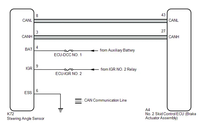
CAUTION / NOTICE / HINT
NOTICE:
Inspect the fuses for circuits related to this system before performing the following procedure.
PROCEDURE
| 1. | CHECK CAN COMMUNICATION SYSTEM |
(a) Check if CAN communication system DTCs are output.
HINT:
Click here

| Result | Proceed to |
|---|---|
| DTCs are not output. | A |
| DTCs are output. | B |
| B |

| INSPECT CAN COMMUNICATION SYSTEM |
|

| 2. | CLEAR DTC |
Pre-procedure1
(a) None
Procedure1
(b) Clear the DTCs.
Chassis > Brake Booster > Clear DTCs Chassis > Brake/EPB > Clear DTCsPost-procedure1
(c) Turn the ignition switch off.
|

| 3. | RECONFIRM DTC |
Pre-procedure1
(a) Turn the ignition switch to ON (READY).
(b) Drive the Toyota Prius vehicle at a speed of 35 km/h (22 mph) and turn the steering wheel to the right and left.
Procedure1
(c) Check that no speed sensor and/or yaw rate sensor DTCs are output.
Chassis > Brake Booster > Trouble Codes Chassis > Brake/EPB > Trouble CodesHINT:
- If a speed sensor, or the yaw rate sensor is malfunctioning, DTCs for the steering angle sensor may be stored even though the steering angle sensor is normal.
- If speed sensor and yaw rate sensor DTCs are output simultaneously, repair these malfunctions and then inspect the steering angle sensor.
| Result | Proceed to |
|---|---|
| DTC C05262A is output. | A |
| Speed sensor and/or yaw rate sensor DTCs are output. | B |
Post-procedure1
(d) None
| B |

| REPAIR CIRCUITS INDICATED BY OUTPUT DTCS |
|

| 4. | CHECK HARNESS AND CONNECTOR (IGR TERMINAL) |
Pre-procedure1
(a) Turn the ignition switch off.
Procedure1
(b) Make sure that there is no looseness at the locking part and the connecting part of the connectors.
OK:
The connector is securely connected.
Pre-procedure2
(c) Disconnect the K72 steering angle sensor connector.
Procedure2
(d) Check both the connector case and the terminals for deformation and corrosion.
OK:
No deformation or corrosion.
Pre-procedure3
(e) Turn the ignition switch to ON.
Procedure3
(f) Measure the voltage according to the value(s) in the table below.
Standard Voltage:
 Click Location & Routing(K72) Click Connector(K72)
 | Tester Connection | Switch Condition | Specified Condition | Result |
|---|---|---|---|
| K72-9 (IGR) - Body ground | Ignition switch ON | 11 to 14 V | V |
Post-procedure1
(g) None
| NG |

| REPAIR OR REPLACE HARNESS OR CONNECTOR |
|

| 5. | CHECK HARNESS AND CONNECTOR (BAT TERMINAL) |
Pre-procedure1
(a) Turn the ignition switch off.
Procedure1
(b) Measure the voltage according to the value(s) in the table below.
Standard Voltage:
 Click Location & Routing(K72) Click Connector(K72)
 | Tester Connection | Condition | Specified Condition | Result |
|---|---|---|---|
| K72-4 (BAT) - Body ground | Always | 11 to 14 V | V |
Post-procedure1
(c) None
| NG |

| REPAIR OR REPLACE HARNESS OR CONNECTOR |
|

| 6. | CHECK HARNESS AND CONNECTOR (ESS TERMINAL) |
(a) Measure the resistance according to the value(s) in the table below.
Standard Resistance:
 Click Location & Routing(K72) Click Connector(K72)
 | Tester Connection | Condition | Specified Condition | Result |
|---|---|---|---|
| K72-6 (ESS) - Body ground | 1 minute or more after disconnecting the cable from the negative (-) auxiliary battery terminal | Below 1 Ω | Ω |
| OK |

| REPLACE STEERING ANGLE SENSOR |
| NG |

| REPAIR OR REPLACE HARNESS OR CONNECTOR |
Steering Angle Sensor Module Component Internal Failure (C052696)
DESCRIPTION
The No. 2 skid control ECU (brake actuator assembly) outputs this DTC when it receives an internal malfunction signal from the steering angle sensor.
| DTC No. | Detection Item | DTC Detection Condition | Trouble Area | MIL | DTC Output from | Priority | Note |
|---|---|---|---|---|---|---|---|
| C052696 | Steering Angle Sensor Module Component Internal Failure | With the BS terminal voltage 9.5 to 17.4 V, the No. 2 skid control ECU (brake actuator assembly) receives an error signal from the steering angle sensor. | Steering angle sensor | Does not come on | Brake/EPB | A | Output ECU: No. 2 skid control ECU (brake actuator assembly) |
PROCEDURE
| 1. | REPLACE STEERING ANGLE SENSOR |
HINT:
Click here


| NEXT |

| END |
ABS Pump Motor Control Circuit Short to Ground or Open (C052C14,C052C16,C052C17,C052C49,C052F14)
DESCRIPTION
The motor relay and motor fail-safe relay are built into the brake actuator assembly.
When the No. 2 skid control ECU (brake actuator assembly) operates ABS, TRAC, VSC, or brake assist, etc., the motor relay turns ON and drives the pump motor built into the brake actuator assembly.
If any DTCs related to motor supply power are stored, fail-safe is performed and supply of power to the motor relay is cut by the motor fail-safe relay.
If the voltage supplied to the motor relay (BM terminal) is below the DTC detection threshold due to low voltage from the auxiliary battery or DC/DC converter circuit, these DTCs may be stored.
| DTC No. | Detection Item | DTC Detection Condition | Trouble Area | MIL | DTC Output from | Priority | Note |
|---|---|---|---|---|---|---|---|
| C052C14 | ABS Pump Motor Control Circuit Short to Ground or Open | When the voltage at terminal BS is between 9.5 and 17.4 V and the motor is being driven at full power, an abnormal voltage is detected for 0.12 seconds or more. |
| Comes on | Brake/EPB | A |
|
| C052C16 | ABS Pump Motor Control Circuit Voltage Below Threshold | When the voltage at terminal BS is between 9.5 and 17.4 V and the motor is stopped, the detected motor voltage is excessively low for 2 seconds or more. | No. 2 skid control ECU (brake actuator assembly) | Comes on | Brake/EPB | A |
|
| C052C17 | ABS Pump Motor Control Circuit Voltage Above Threshold | When the voltage at terminal BS is between 9.5 and 17.4 V and the motor is stopped, the detected motor voltage is excessively high for 2 seconds or more. | No. 2 skid control ECU (brake actuator assembly) | Comes on | Brake/EPB | A |
|
| C052C49 | ABS Pump Motor Control Internal Electronic Failure | Either of the following is detected:
|
| Comes on | Brake/EPB | A |
|
| C052F14 | ABS Pump Motor Supply Voltage Circuit Short to Ground or Open | When voltage at BS terminal is 9.5 V or more, open in BM terminal continues for 1 second or more. |
| Does not come on | Brake/EPB | A | Output ECU: No. 2 skid control ECU (brake actuator assembly) |
MONITOR DESCRIPTION
-
If any of the following conditions are met for a certain amount of time, the No. 2 skid control ECU (brake actuator assembly) judges that the gate voltage is abnormal, the MIL is illuminated and a DTC is stored.
- The command to reverse battery protection MOS monitor is on and the reverse battery protection MOS gate voltage malfunction (IC Data) monitor is on.
- The motor relay overcurrent signal monitor is off, freewheeling MOS overcurrent signal monitor is off and the motor relay gate voltage malfunction monitor is on.
-
When there is a command to turn off the motor relay, motor fail-safe relay, reverse battery protection MOS and freewheeling MOS, and any of the following conditions are met, the No. 2 skid control ECU (brake actuator assembly) judges that the gate voltage is abnormal, the MIL is illuminated and a DTC is stored.
- The motor relay gate voltage malfunction monitor is on.
- The reverse battery protection MOS gate voltage malfunction monitor is on.
- The freewheeling MOS gate voltage malfunction monitor is on.
- When there is a command to turn off the motor relay, motor fail-safe relay and reverse battery protection MOS, command to turn on the freewheeling MOS, and the freewheeling MOS gate voltage malfunction monitor is ON, the No. 2 skid control ECU (brake actuator assembly) judges that the gate voltage is abnormal, the MIL is illuminated and a DTC is stored.
- When there is a command to turn off the freewheeling MOS, motor fail-safe relay and reverse battery protection MOS, command to turn on the motor relay, and the motor relay gate voltage malfunction monitor is ON, the No. 2 skid control ECU (brake actuator assembly) judges that the gate voltage is abnormal, the MIL is illuminated and a DTC is stored.
- When there is a command to turn off the motor relay, motor fail-safe relay and freewheeling MOS, command to turn on the reverse battery protection MOS, and the reverse battery protection MOS gate voltage malfunction monitor is ON, the No. 2 skid control ECU (brake actuator assembly) judges that the gate voltage is abnormal, the MIL is illuminated and a DTC is stored.
- When the voltage upstream or downstream of the motor is outside of the specified range, the No. 2 skid control ECU (brake actuator assembly) judges that the gate voltage is abnormal or the motor circuit is malfunctioning, the MIL is illuminated and a DTC is stored.
- When this is no history of motor power supply voltage drop, there is a command to turn on the MROC, MRSUV, and overcurrent is detected in the motor circuit, the No. 2 skid control ECU (brake actuator assembly) judges that there is overcurrent, the MIL is illuminated and a DTC is stored.
- When the freewheeling MOS overcurrent signal is ON, the No. 2 skid control ECU (brake actuator assembly) judges that there is a malfunction, the MIL is illuminated and a DTC is stored.
MONITOR STRATEGY
| Related DTCs | C052B (Case 1 to 7): ABS pump motor performance (gate voltage) C052B (Case 8): ABS pump motor performance (motor relay current) C052B (Case 9): ABS pump motor performance (freewheeling MOS current) C052D: ABS pump motor circuit high C052E (Case 1 to 4): ABS pump motor circuit open (motor circuit) C052E (Case 5 and 6): ABS pump motor circuit open (motor relay) |
| Required Sensors/Components(Main) | No. 2 skid control ECU (brake actuator assembly) |
| Required Sensors/Components(Related) | - |
| Frequency of Operation | Continuous |
| Duration | 0.12 seconds: C052B (Case 3 to 5), C052D (Case 5) and C052E (Case 3 to 6) 0.054 seconds: C052B (Case 8 and 9) 2 seconds: C052D (Case 2) 2.004 seconds: C052E (Case 2) 4 seconds: C052E (Case 1) 4.002 seconds: C052B (Case 6 and 7) and C052D (Case 3 to 4) -: C052B (Case 1 and 2) and C052D (Case 1) |
| MIL Operation | Immediately |
| Sequence of Operation | None |
TYPICAL ENABLING CONDITIONS
C052B (Case 1)| Monitor runs whenever the following DTCs are not stored | C052B (Case 1 to 7): ABS pump motor performance (gate voltage) C052B (Case 8): ABS pump motor performance (motor relay current) C052B (Case 9): ABS pump motor performance (freewheeling MOS current) C052D: ABS pump motor circuit high C052E (Case 1 to 4): ABS pump motor circuit open (motor circuit) C052E (Case 5 and 6): ABS pump motor circuit open (motor relay) C0597: ABS hold solenoid performance C12A7 (Case 1 and 2): ABS hold solenoid (FL) circuit open C12A7 (Case 3): ABS hold solenoid (FL) circuit low C12A8 (Case 1): ABS hold solenoid (FL) circuit high (solenoid Off current) C12A8 (Case 2 and 3): ABS hold solenoid (FL) circuit high (IC data) C12A8 (Case 4): ABS hold solenoid (FL) circuit high (solenoid On current) C12B2: ABS release solenoid (FL) circuit low C12B3: ABS release solenoid (FL) circuit high C12BD (Case 1 and 2): ABS hold solenoid (FR) circuit open C12BD (Case 3): ABS hold solenoid (FR) circuit low C12BE (Case 1): ABS hold solenoid (FR) circuit high (solenoid Off current) C12BE (Case 2 and 3): ABS hold solenoid (FR) circuit high (IC data) C12BE (Case 4): ABS hold solenoid (FR) circuit high (solenoid On current) C12C8: ABS release solenoid (FR) circuit low C12C9: ABS release solenoid (FR) circuit high C12D3 (Case 1 and 2): ABS hold solenoid (RL) circuit open C12D3 (Case 3): ABS hold solenoid (RL) circuit low C12D4 (Case 1): ABS hold solenoid (RL) circuit high (solenoid Off current) C12D4 (Case 2 and 3): ABS hold solenoid (RL) circuit high (IC data) C12D4 (Case 4): ABS hold solenoid (RL) circuit high (solenoid On current) C12DE: ABS release solenoid (RL) circuit low C12DF: ABS release solenoid (RL) circuit high C12E9 (Case 1 and 2): ABS hold solenoid (RR) circuit open C12E9 (Case 3): ABS hold solenoid (RR) circuit low C12EA (Case 1): ABS hold solenoid (RR) circuit high (solenoid Off current) C12EA (Case 2 and 3): ABS hold solenoid (RR) circuit high (IC data) C12EA (Case 4): ABS hold solenoid (RR) circuit high (solenoid On current) C12F4: ABS release solenoid (RR) circuit low C12F5: ABS release solenoid (RR) circuit high C12F6: ABS hold solenoid other functional C12F7: ABS hold solenoid other functional C13BF: SM solenoid other functional C13C2 (Case 1 and 2): SM1 solenoid circuit open C13C2 (Case 3): SM1 solenoid circuit low C13C3 (Case 1): SM1 solenoid circuit high (solenoid Off current) C13C3 (Case 2 and 3): SM1 solenoid circuit high (IC data) C13C3 (Case 4): SM1 solenoid circuit high (solenoid On current) C13CB (Case 1 and 2): SM2 solenoid circuit open C13CB (Case 3): SM2 solenoid circuit low C13CC (Case 1): SM2 solenoid circuit high (solenoid Off current) C13CC (Case 2 and 3): SM2 solenoid circuit high (IC data) C13CC (Case 4): SM2 solenoid circuit high (solenoid On current) C137D: Brake system voltage circuit high C1427: ABS pump motor stuck C143B: Brake system voltage power supply relay circuit high C143C: Brake system voltage power supply relay circuit open |
| All of the following conditions are met | A, B, C, D and E |
| A. BM voltage | 6 V or higher |
| B. Following condition is met | More than 0.22 seconds |
| BS voltage | 9.5 V or higher |
| C. Following condition is met | More than 0.22 seconds |
| BS voltage | 17.4 V or less |
| D. IGR voltage | Higher than 10 V |
| E. IGP voltage | Higher than 10 V |
| Monitor runs whenever the following DTCs are not stored | C052B (Case 1 to 7): ABS pump motor performance (gate voltage) C052B (Case 8): ABS pump motor performance (motor relay current) C052B (Case 9): ABS pump motor performance (freewheeling MOS current) C052D: ABS pump motor circuit high C052E (Case 1 to 4): ABS pump motor circuit open (motor circuit) C052E (Case 5 and 6): ABS pump motor circuit open (motor relay) C137D: Brake system voltage circuit high |
| All of the following conditions are met | A, B, C, D, E, F, G, H, I, J, K and L |
| A. ECU status | Premain |
| B. Following condition is met | More than 0.22 seconds |
| BS voltage | 9.5 V or higher |
| C. Following condition is met | More than 0.22 seconds |
| BS voltage | 17.4 V or less |
| D. BM voltage | 6 V or higher |
| E. Motor relay input signal permission | Off |
| F. Command to motor relay | Off |
| G. Motor duty output order value | 0% |
| H. Command to reverse battery protection MOS | Off |
| I. Command to freewheeling MOS | Off |
| J. Command to motor failsafe relay | Off |
| K. IGR voltage | Higher than 10 V |
| L. IGP voltage | Higher than 10 V |
| Monitor runs whenever the following DTCs are not stored | C052B (Case 1 to 7): ABS pump motor performance (gate voltage) C052B (Case 8): ABS pump motor performance (motor relay current) C052B (Case 9): ABS pump motor performance (freewheeling MOS current) C052D: ABS pump motor circuit high C052E (Case 1 to 4): ABS pump motor circuit open (motor circuit) C052E (Case 5 and 6): ABS pump motor circuit open (motor relay) C137D: Brake system voltage circuit high |
| All of the following conditions are met | A, B, C, D, E, F, G, H, I, J, K and L |
| A. ECU status | Premain |
| B. Following condition is met | More than 0.22 seconds |
| BS voltage | 9.5 V or higher |
| C. Following condition is met | More than 0.22 seconds |
| BS voltage | 17.4 V or less |
| D. BM voltage | 6 V or higher |
| E. Motor relay input signal permission | On |
| F. Command to motor relay | Off |
| G. Motor duty output order value | 0% |
| H. Command to reverse battery protection MOS | Off |
| I. Command to freewheeling MOS | On |
| J. Command to motor failsafe relay | Off |
| K. IGR voltage | Higher than 10 V |
| L. IGP voltage | Higher than 10 V |
| Monitor runs whenever the following DTCs are not stored | C052B (Case 1 to 7): ABS pump motor performance (gate voltage) C052B (Case 8): ABS pump motor performance (motor relay current) C052B (Case 9): ABS pump motor performance (freewheeling MOS current) C052D: ABS pump motor circuit high C052E (Case 1 to 4): ABS pump motor circuit open (motor circuit) C052E (Case 5 and 6): ABS pump motor circuit open (motor relay) C137D: Brake system voltage circuit high |
| All of the following conditions are met | A, B, C, D, E, F, G, H, I, J, K and L |
| A. ECU status | Premain |
| B. Following condition is met | More than 0.22 seconds |
| BS voltage | 9.5 V or higher |
| C. Following condition is met | More than 0.22 seconds |
| BS voltage | 17.4 V or less |
| D. BM voltage | 6 V or higher |
| E. Motor relay input signal permission | On |
| F. Command to motor relay | On |
| G. Motor duty output order value | 100% |
| H. Command to reverse battery protection MOS | Off |
| I. Command to freewheeling MOS | Off |
| J. Command to motor failsafe relay | Off |
| K. IGR voltage | Higher than 10 V |
| L. IGP voltage | Higher than 10 V |
| Monitor runs whenever the following DTCs are not stored | C052B (Case 1 to 7): ABS pump motor performance (gate voltage) C052B (Case 8): ABS pump motor performance (motor relay current) C052B (Case 9): ABS pump motor performance (freewheeling MOS current) C052D: ABS pump motor circuit high C052E (Case 1 to 4): ABS pump motor circuit open (motor circuit) C052E (Case 5 and 6): ABS pump motor circuit open (motor relay) C137D: Brake system voltage circuit high |
| All of the following conditions are met | A, B, C, D, E, F, G, H, I, J, K and L |
| A. ECU status | Premain |
| B. Following condition is met | More than 0.22 seconds |
| BS voltage | 9.5 V or higher |
| C. Following condition is met | More than 0.22 seconds |
| BS voltage | 17.4 V or less |
| D. BM voltage | 6 V or higher |
| E. Motor relay input signal permission | Off |
| F. Command to motor relay | Off |
| G. Motor duty output order value | 0% |
| H. Command to reverse battery protection MOS | On |
| I. Command to freewheeling MOS | Off |
| J. Command to motor failsafe relay | Off |
| K. IGR voltage | Higher than 10 V |
| L. IGP voltage | Higher than 10 V |
| Monitor runs whenever the following DTCs are not stored | C052B (Case 1 to 7): ABS pump motor performance (gate voltage) C052B (Case 8): ABS pump motor performance (motor relay current) C052B (Case 9): ABS pump motor performance (freewheeling MOS current) C052D: ABS pump motor circuit high C052E (Case 1 to 4): ABS pump motor circuit open (motor circuit) C052E (Case 5 and 6): ABS pump motor circuit open (motor relay) C137D: Brake system voltage circuit high |
| All of the following conditions are met | A, B, C, D, E, F, G, H, I, J, K, L and M |
| A. ECU status | Premain |
| B. Following condition is met | More than 0.22 seconds |
| BS voltage | 17.4 V or less |
| C. BM voltage | 6 V or higher |
| D. Motor relay input signal permission | On |
| E. Command to motor relay | On |
| F. Motor duty output order value | 100% |
| G. Command to reverse battery protection MOS | Off |
| H. Command to freewheeling MOS | Off |
| I. Command to motor failsafe relay | Off |
| J. ASIC output permission | Off |
| K. BS voltage | 9.5 V or higher |
| L. IGR voltage | Higher than 10 V |
| M. IGP voltage | Higher than 10 V |
| Monitor runs whenever the following DTCs are not stored | C052B (Case 1 to 7): ABS pump motor performance (gate voltage) C052B (Case 8): ABS pump motor performance (motor relay current) C052B (Case 9): ABS pump motor performance (freewheeling MOS current) C052D: ABS pump motor circuit high C052E (Case 1 to 4): ABS pump motor circuit open (motor circuit) C052E (Case 5 and 6): ABS pump motor circuit open (motor relay) C137D: Brake system voltage circuit high |
| All of the following conditions are met | A, B, C, D, E, F, G, H, I, J, K and L |
| A. ECU status | Premain |
| B. Following condition is met | More than 0.22 seconds |
| BS voltage | 9.5 V or higher |
| C. Following condition is met | More than 0.22 seconds |
| BS voltage | 17.4 V or less |
| D. BM voltage | 6 V or higher |
| E Motor relay input signal permission | Off |
| F. Command to motor relay | On |
| G. Motor duty output order value | 100% |
| H. Command to reverse battery protection MOS | Off |
| I. Command to freewheeling MOS | Off |
| J. Command to motor failsafe relay | Off |
| K. IGR voltage | Higher than 10 V |
| L. IGP voltage | Higher than 10 V |
| Monitor runs whenever the following DTCs are not stored | C052B (Case 1 to 7): ABS pump motor performance (gate voltage) C052B (Case 8): ABS pump motor performance (motor relay current) C052B (Case 9): ABS pump motor performance (freewheeling MOS current) C052D: ABS pump motor circuit high C052E (Case 1 to 4): ABS pump motor circuit open (motor circuit) C052E (Case 5 and 6): ABS pump motor circuit open (motor relay) C0597: ABS hold solenoid performance C12A7 (Case 1 and 2): ABS hold solenoid (FL) circuit open C12A7 (Case 3): ABS hold solenoid (FL) circuit low C12A8 (Case 1): ABS hold solenoid (FL) circuit high (solenoid Off current) C12A8 (Case 2 and 3): ABS hold solenoid (FL) circuit high (IC data) C12A8 (Case 4): ABS hold solenoid (FL) circuit high (solenoid On current) C12B2: ABS release solenoid (FL) circuit low C12B3: ABS release solenoid (FL) circuit high C12BD (Case 1 and 2): ABS hold solenoid (FR) circuit open C12BD (Case 3): ABS hold solenoid (FR) circuit low C12BE (Case 1): ABS hold solenoid (FR) circuit high (solenoid Off current) C12BE (Case 2 and 3): ABS hold solenoid (FR) circuit high (IC data) C12BE (Case 4): ABS hold solenoid (FR) circuit high (solenoid On current) C12C8: ABS release solenoid (FR) circuit low C12C9: ABS release solenoid (FR) circuit high C12D3 (Case 1 and 2): ABS hold solenoid (RL) circuit open C12D3 (Case 3): ABS hold solenoid (RL) circuit low C12D4 (Case 1): ABS hold solenoid (RL) circuit high (solenoid Off current) C12D4 (Case 2 and 3): ABS hold solenoid (RL) circuit high (IC data) C12D4 (Case 4): ABS hold solenoid (RL) circuit high (solenoid On current) C12DE: ABS release solenoid (RL) circuit low C12DF: ABS release solenoid (RL) circuit high C12E9 (Case 1 and 2): ABS hold solenoid (RR) circuit open C12E9 (Case 3): ABS hold solenoid (RR) circuit low C12EA (Case 1): ABS hold solenoid (RR) circuit high (solenoid Off current) C12EA (Case 2 and 3): ABS hold solenoid (RR) circuit high (IC data) C12EA (Case 4): ABS hold solenoid (RR) circuit high (solenoid On current) C12F4: ABS release solenoid (RR) circuit low C12F5: ABS release solenoid (RR) circuit high C12F6: ABS hold solenoid other functional C12F7: ABS hold solenoid other functional C13BF: SM solenoid other functional C13C2 (Case 1 and 2): SM1 solenoid circuit open C13C2 (Case 3): SM1 solenoid circuit low C13C3 (Case 1): SM1 solenoid circuit high (solenoid Off current) C13C3 (Case 2 and 3): SM1 solenoid circuit high (IC data) C13C3 (Case 4): SM1 solenoid circuit high (solenoid On current) C13CB (Case 1 and 2): SM2 solenoid circuit open C13CB (Case 3): SM2 solenoid circuit low C13CC (Case 1): SM2 solenoid circuit high (solenoid Off current) C13CC (Case 2 and 3): SM2 solenoid circuit high (IC data) C13CC (Case 4): SM2 solenoid circuit high (solenoid On current) C137D: Brake system voltage circuit high C1427: ABS pump motor stuck C143B: Brake system voltage power supply relay circuit high C143C: Brake system voltage power supply relay circuit open |
| All of the following conditions are met | A, B, C, D, E, F and G |
| A. Following condition is met | More than 0.22 seconds |
| BS voltage | 9.5 V or higher |
| B. Following condition is met | More than 0.22 seconds |
| BS voltage | 17.4 V or less |
| C. Command to motor relay | On |
| D. History of motor power supply voltage drop | Off |
| E. IGR voltage | Higher than 10 V |
| F. IGP voltage | Higher than 10 V |
| G. BM voltage | 6 V or higher |
| Monitor runs whenever the following DTCs are not stored | C052B (Case 1 to 7): ABS pump motor performance (gate voltage) C052B (Case 8): ABS pump motor performance (motor relay current) C052B (Case 9): ABS pump motor performance (freewheeling MOS current) C052D: ABS pump motor circuit high C052E (Case 1 to 4): ABS pump motor circuit open (motor circuit) C052E (Case 5 and 6): ABS pump motor circuit open (motor relay) C12A7 (Case 1 and 2): ABS hold solenoid (FL) circuit open C12A7 (Case 3): ABS hold solenoid (FL) circuit low C12A8 (Case 1): ABS hold solenoid (FL) circuit high (solenoid Off current) C12A8 (Case 2 and 3): ABS hold solenoid (FL) circuit high (IC data) C12A8 (Case 4): ABS hold solenoid (FL) circuit high (solenoid On current) C12B2: ABS release solenoid (FL) circuit low C12B3: ABS release solenoid (FL) circuit high C12BD (Case 1 and 2): ABS hold solenoid (FR) circuit open C12BD (Case 3): ABS hold solenoid (FR) circuit low C12BE (Case 1): ABS hold solenoid (FR) circuit high (solenoid Off current) C12BE (Case 2 and 3): ABS hold solenoid (FR) circuit high (IC data) C12BE (Case 4): ABS hold solenoid (FR) circuit high (solenoid On current) C12C8: ABS release solenoid (FR) circuit low C12C9: ABS release solenoid (FR) circuit high C12D3 (Case 1 and 2): ABS hold solenoid (RL) circuit open C12D3 (Case 3): ABS hold solenoid (RL) circuit low C12D4 (Case 1): ABS hold solenoid (RL) circuit high (solenoid Off current) C12D4 (Case 2 and 3): ABS hold solenoid (RL) circuit high (IC data) C12D4 (Case 4): ABS hold solenoid (RL) circuit high (solenoid On current) C12E9 (Case 1 and 2): ABS hold solenoid (RR) circuit open C12E9 (Case 3): ABS hold solenoid (RR) circuit low C12EA (Case 1): ABS hold solenoid (RR) circuit high (solenoid Off current) C12EA (Case 2 and 3): ABS hold solenoid (RR) circuit high (IC data) C12EA (Case 4): ABS hold solenoid (RR) circuit high (solenoid On current) C12F6: ABS hold solenoid other functional C12F7: ABS hold solenoid other functional C13BF: SM solenoid other functional C13C2 (Case 1 and 2): SM1 solenoid circuit open C13C2 (Case 3): SM1 solenoid circuit low C13C3 (Case 1): SM1 solenoid circuit high (solenoid Off current) C13C3 (Case 2 and 3): SM1 solenoid circuit high (IC data) C13C3 (Case 4): SM1 solenoid circuit high (solenoid On current) C13CB (Case 1 and 2): SM2 solenoid circuit open C13CB (Case 3): SM2 solenoid circuit low C13CC (Case 1): SM2 solenoid circuit high (solenoid Off current) C13CC (Case 2 and 3): SM2 solenoid circuit high (IC data) C13CC (Case 4): SM2 solenoid circuit high (solenoid On current) C137D: Brake system voltage circuit high C1427: ABS pump motor stuck C143B: Brake system voltage power supply relay circuit high C143C: Brake system voltage power supply relay circuit open |
| All of the following conditions are met | - |
| BM voltage | 6 V or higher |
| BS voltage | 9.5 V or higher |
| IGR voltage | Higher than 10 V |
| IGP voltage | Higher than 10 V |
| Monitor runs whenever the following DTCs are not stored | C052B (Case 1 to 7): ABS pump motor performance (gate voltage) C052B (Case 8): ABS pump motor performance (motor relay current) C052B (Case 9): ABS pump motor performance (freewheeling MOS current) C052E (Case 1 to 4): ABS pump motor circuit open (motor circuit) C052E (Case 5 and 6): ABS pump motor circuit open (motor relay) C0597: ABS hold solenoid performance C12A7 (Case 1 and 2): ABS hold solenoid (FL) circuit open C12A7 (Case 3): ABS hold solenoid (FL) circuit low C12A8 (Case 1): ABS hold solenoid (FL) circuit high (solenoid Off current) C12A8 (Case 2 and 3): ABS hold solenoid (FL) circuit high (IC data) C12A8 (Case 4): ABS hold solenoid (FL) circuit high (solenoid On current) C12B2: ABS release solenoid (FL) circuit low C12B3: ABS release solenoid (FL) circuit high C12BD (Case 1 and 2): ABS hold solenoid (FR) circuit open C12BD (Case 3): ABS hold solenoid (FR) circuit low C12BE (Case 1): ABS hold solenoid (FR) circuit high (solenoid Off current) C12BE (Case 2 and 3): ABS hold solenoid (FR) circuit high (IC data) C12BE (Case 4): ABS hold solenoid (FR) circuit high (solenoid On current) C12C8: ABS release solenoid (FR) circuit low C12C9: ABS release solenoid (FR) circuit high C12D3 (Case 1 and 2): ABS hold solenoid (RL) circuit open C12D3 (Case 3): ABS hold solenoid (RL) circuit low C12D4 (Case 1): ABS hold solenoid (RL) circuit high (solenoid Off current) C12D4 (Case 2 and 3): ABS hold solenoid (RL) circuit high (IC data) C12D4 (Case 4): ABS hold solenoid (RL) circuit high (solenoid On current) C12DE: ABS release solenoid (RL) circuit low C12DF: ABS release solenoid (RL) circuit high C12E9 (Case 1 and 2): ABS hold solenoid (RR) circuit open C12E9 (Case 3): ABS hold solenoid (RR) circuit low C12EA (Case 1): ABS hold solenoid (RR) circuit high (solenoid Off current) C12EA (Case 2 and 3): ABS hold solenoid (RR) circuit high (IC data) C12EA (Case 4): ABS hold solenoid (RR) circuit high (solenoid On current) C12F4: ABS release solenoid (RR) circuit low C12F5: ABS release solenoid (RR) circuit high C12F6: ABS hold solenoid other functional C12F7: ABS hold solenoid other functional C13BF: SM solenoid other functional C13C2 (Case 1 and 2): SM1 solenoid circuit open C13C2 (Case 3): SM1 solenoid circuit low C13C3 (Case 1): SM1 solenoid circuit high (solenoid Off current) C13C3 (Case 2 and 3): SM1 solenoid circuit high (IC data) C13C3 (Case 4): SM1 solenoid circuit high (solenoid On current) C13CB (Case 1 and 2): SM2 solenoid circuit open C13CB (Case 3): SM2 solenoid circuit low C13CC (Case 1): SM2 solenoid circuit high (solenoid Off current) C13CC (Case 2 and 3): SM2 solenoid circuit high (IC data) C13CC (Case 4): SM2 solenoid circuit high (solenoid On current) C137D: Brake system voltage circuit high C1427: ABS pump motor stuck C143B: Brake system voltage power supply relay circuit high C143C: Brake system voltage power supply relay circuit open |
| All of the following conditions are met | A, B, C, D, E, F and G |
| A. Following condition is met | More than 0.22 seconds |
| BS voltage | 9.5 V or higher |
| B. Following condition is met | More than 0.22 seconds |
| BS voltage | 17.4 V or less |
| C. Command to motor relay | On |
| D. Motor stop status | On |
| E. IGR voltage | Higher than 10 V |
| F. IGP voltage | Higher than 10 V |
| G. BM voltage | 6 V or higher |
| Monitor runs whenever the following DTCs are not stored | C052B (Case 1 to 7): ABS pump motor performance (gate voltage) C052B (Case 8): ABS pump motor performance (motor relay current) C052B (Case 9): ABS pump motor performance (freewheeling MOS current) C052E (Case 1 to 4): ABS pump motor circuit open (motor circuit) C052E (Case 5 and 6): ABS pump motor circuit open (motor relay) C0597: ABS hold solenoid performance C12A7 (Case 1 and 2): ABS hold solenoid (FL) circuit open C12A7 (Case 3): ABS hold solenoid (FL) circuit low C12A8 (Case 1): ABS hold solenoid (FL) circuit high (solenoid Off current) C12A8 (Case 2 and 3): ABS hold solenoid (FL) circuit high (IC data) C12A8 (Case 4): ABS hold solenoid (FL) circuit high (solenoid On current) C12B2: ABS release solenoid (FL) circuit low C12B3: ABS release solenoid (FL) circuit high C12BD (Case 1 and 2): ABS hold solenoid (FR) circuit open C12BD (Case 3): ABS hold solenoid (FR) circuit low C12BE (Case 1): ABS hold solenoid (FR) circuit high (solenoid Off current) C12BE (Case 2 and 3): ABS hold solenoid (FR) circuit high (IC data) C12BE (Case 4): ABS hold solenoid (FR) circuit high (solenoid On current) C12C8: ABS release solenoid (FR) circuit low C12C9: ABS release solenoid (FR) circuit high C12D3 (Case 1 and 2): ABS hold solenoid (RL) circuit open C12D3 (Case 3): ABS hold solenoid (RL) circuit low C12D4 (Case 1): ABS hold solenoid (RL) circuit high (solenoid Off current) C12D4 (Case 2 and 3): ABS hold solenoid (RL) circuit high (IC data) C12D4 (Case 4): ABS hold solenoid (RL) circuit high (solenoid On current) C12DE: ABS release solenoid (RL) circuit low C12DF: ABS release solenoid (RL) circuit high C12E9 (Case 1 and 2): ABS hold solenoid (RR) circuit open C12E9 (Case 3): ABS hold solenoid (RR) circuit low C12EA (Case 1): ABS hold solenoid (RR) circuit high (solenoid Off current) C12EA (Case 2 and 3): ABS hold solenoid (RR) circuit high (IC data) C12EA (Case 4): ABS hold solenoid (RR) circuit high (solenoid On current) C12F4: ABS release solenoid (RR) circuit low C12F5: ABS release solenoid (RR) circuit high C12F6: ABS hold solenoid other functional C12F7: ABS hold solenoid other functional C13BF: SM solenoid other functional C13C2 (Case 1 and 2): SM1 solenoid circuit open C13C2 (Case 3): SM1 solenoid circuit low C13C3 (Case 1): SM1 solenoid circuit high (solenoid Off current) C13C3 (Case 2 and 3): SM1 solenoid circuit high (IC data) C13C3 (Case 4): SM1 solenoid circuit high (solenoid On current) C13CB (Case 1 and 2): SM2 solenoid circuit open C13CB (Case 3): SM2 solenoid circuit low C13CC (Case 1): SM2 solenoid circuit high (solenoid Off current) C13CC (Case 2 and 3): SM2 solenoid circuit high (IC data) C13CC (Case 4): SM2 solenoid circuit high (solenoid On current) C137D: Brake system voltage circuit high C1427: ABS pump motor stuck C143B: Brake system voltage power supply relay circuit high C143C: Brake system voltage power supply relay circuit open |
| All of the following conditions are met | A, B, C, D, E and F |
| A. Following condition is met | More than 0.22 seconds |
| BS voltage | 9.5 V or higher |
| B. Following condition is met | More than 0.22 seconds |
| BS voltage | 17.4 V or less |
| C. Command to motor relay | Off |
| D. IGR voltage | Higher than 10 V |
| E. IGP voltage | Higher than 10 V |
| F. BM voltage | 6 V or higher |
| Monitor runs whenever the following DTCs are not stored | C052B (Case 1 to 7): ABS pump motor performance (gate voltage) C052B (Case 8): ABS pump motor performance (motor relay current) C052B (Case 9): ABS pump motor performance (freewheeling MOS current) C052E (Case 1 to 4): ABS pump motor circuit open (motor circuit) C052E (Case 5 and 6): ABS pump motor circuit open (motor relay) C137D: Brake system voltage circuit high |
| All of the following conditions are met | A, B, C, D, E, F, G, H, I, J, K and L |
| A. ECU status | Premain |
| B. Following condition is met | More than 0.22 seconds |
| BS voltage | 9.5 V or higher |
| C. Following condition is met | More than 0.22 seconds |
| BS voltage | 17.4 V or less |
| D. BM voltage | 6 V or higher |
| E. Motor relay input signal permission | Off |
| F. Command to motor relay | Off |
| G. Motor duty output order value | 0% |
| H. Command to reverse battery protection MOS | Off |
| I. Command to freewheeling MOS | Off |
| J. Command to motor failsafe relay | Off |
| K. IGR voltage | Higher than 10 V |
| L. IGP voltage | Higher than 10 V |
| Monitor runs whenever the following DTCs are not stored | C052B (Case 1 to 7): ABS pump motor performance (gate voltage) C052B (Case 8): ABS pump motor performance (motor relay current) C052B (Case 9): ABS pump motor performance (freewheeling MOS current) C052D: ABS pump motor circuit high C052E (Case 1 to 4): ABS pump motor circuit open (motor circuit) C052E (Case 5 and 6): ABS pump motor circuit open (motor relay) C0597: ABS hold solenoid performance C12A7 (Case 1 and 2): ABS hold solenoid (FL) circuit open C12A7 (Case 3): ABS hold solenoid (FL) circuit low C12A8 (Case 1): ABS hold solenoid (FL) circuit high (solenoid Off current) C12A8 (Case 2 and 3): ABS hold solenoid (FL) circuit high (IC data) C12A8 (Case 4): ABS hold solenoid (FL) circuit high (solenoid On current) C12B2: ABS release solenoid (FL) circuit low C12B3: ABS release solenoid (FL) circuit high C12BD (Case 1 and 2): ABS hold solenoid (FR) circuit open C12BD (Case 3): ABS hold solenoid (FR) circuit low C12BE (Case 1): ABS hold solenoid (FR) circuit high (solenoid Off current) C12BE (Case 2 and 3): ABS hold solenoid (FR) circuit high (IC data) C12BE (Case 4): ABS hold solenoid (FR) circuit high (solenoid On current) C12C8: ABS release solenoid (FR) circuit low C12C9: ABS release solenoid (FR) circuit high C12D3 (Case 1 and 2): ABS hold solenoid (RL) circuit open C12D3 (Case 3): ABS hold solenoid (RL) circuit low C12D4 (Case 1): ABS hold solenoid (RL) circuit high (solenoid Off current) C12D4 (Case 2 and 3): ABS hold solenoid (RL) circuit high (IC data) C12D4 (Case 4): ABS hold solenoid (RL) circuit high (solenoid On current) C12DE: ABS release solenoid (RL) circuit low C12DF: ABS release solenoid (RL) circuit high C12E9 (Case 1 and 2): ABS hold solenoid (RR) circuit open C12E9 (Case 3): ABS hold solenoid (RR) circuit low C12EA (Case 1): ABS hold solenoid (RR) circuit high (solenoid Off current) C12EA (Case 2 and 3): ABS hold solenoid (RR) circuit high (IC data) C12EA (Case 4): ABS hold solenoid (RR) circuit high (solenoid On current) C12F4: ABS release solenoid (RR) circuit low C12F5: ABS release solenoid (RR) circuit high C12F6: ABS hold solenoid other functional C12F7: ABS hold solenoid other functional C13BF: SM solenoid other functional C13C2 (Case 1 and 2): SM1 solenoid circuit open C13C2 (Case 3): SM1 solenoid circuit low C13C3 (Case 1): SM1 solenoid circuit high (solenoid Off current) C13C3 (Case 2 and 3): SM1 solenoid circuit high (IC data) C13C3 (Case 4): SM1 solenoid circuit high (solenoid On current) C13CB (Case 1 and 2): SM2 solenoid circuit open C13CB (Case 3): SM2 solenoid circuit low C13CC (Case 1): SM2 solenoid circuit high (solenoid Off current) C13CC (Case 2 and 3): SM2 solenoid circuit high (IC data). C13CC (Case 4): SM2 solenoid circuit high (solenoid On current) C137D: Brake system voltage circuit high C1427: ABS pump motor stuck C143B: Brake system voltage power supply relay circuit high C143C: Brake system voltage power supply relay circuit open |
| All of the following conditions are met | A, B, C, D, E and F |
| A. Following condition is met | More than 0.22 seconds |
| BS voltage | 9.5 V or higher |
| B. Following condition is met | More than 0.22 seconds |
| BS voltage | 17.4 V or less |
| C. Motor stop status | On |
| D. IGR voltage | Higher than 10 V |
| E. IGP voltage | Higher than 10 V |
| F. BM voltage | 6 V or higher |
| Monitor runs whenever the following DTCs are not stored | C052B (Case 1 to 7): ABS pump motor performance (gate voltage) C052B (Case 8): ABS pump motor performance (motor relay current) C052B (Case 9): ABS pump motor performance (freewheeling MOS current) C052D: ABS pump motor circuit high C052E (Case 1 to 4): ABS pump motor circuit open (motor circuit) C052E (Case 5 and 6): ABS pump motor circuit open (motor relay) C137D: Brake system voltage circuit high |
| All of the following conditions are met | A, B, C, D, E, F, G, H, I, J, K and L |
| A. ECU status | Premain |
| B. Following condition is met | More than 0.22 seconds |
| BS voltage | 9.5 V or higher |
| C. Following condition is met | More than 0.22 seconds |
| BS voltage | 17.4 V or less |
| D. BM voltage | 6 V or higher |
| E. Motor relay input signal permission | Off |
| F. Command to motor relay | Off |
| G. Motor duty output order value | 0% |
| H. Command to reverse battery protection MOS | Off |
| I. Command to freewheeling MOS | Off |
| J. Command to motor failsafe relay | On |
| K. IGR voltage | Higher than 10 V |
| L. IGP voltage | Higher than 10 V |
| Monitor runs whenever the following DTCs are not stored | C052B (Case 1 to 7): ABS pump motor performance (gate voltage) C052B (Case 8): ABS pump motor performance (motor relay current) C052B (Case 9): ABS pump motor performance (freewheeling MOS current) C052D: ABS pump motor circuit high C052E (Case 1 to 4): ABS pump motor circuit open (motor circuit) C052E (Case 5 and 6): ABS pump motor circuit open (motor relay) C0597: ABS hold solenoid performance C12A7 (Case 1 and 2): ABS hold solenoid (FL) circuit open C12A7 (Case 3): ABS hold solenoid (FL) circuit low C12A8 (Case 1): ABS hold solenoid (FL) circuit high (solenoid Off current) C12A8 (Case 2 and 3): ABS hold solenoid (FL) circuit high (IC data) C12A8 (Case 4): ABS hold solenoid (FL) circuit high (solenoid On current) C12B2: ABS release solenoid (FL) circuit low C12B3: ABS release solenoid (FL) circuit high C12BD (Case 1 and 2): ABS hold solenoid (FR) circuit open C12BD (Case 3): ABS hold solenoid (FR) circuit low C12BE (Case 1): ABS hold solenoid (FR) circuit high (solenoid Off current) C12BE (Case 2 and 3): ABS hold solenoid (FR) circuit high (IC data) C12BE (Case 4): ABS hold solenoid (FR) circuit high (solenoid On current) C12C8: ABS release solenoid (FR) circuit low C12C9: ABS release solenoid (FR) circuit high C12D3 (Case 1 and 2): ABS hold solenoid (RL) circuit open C12D3 (Case 3): ABS hold solenoid (RL) circuit low C12D4 (Case 1): ABS hold solenoid (RL) circuit high (solenoid Off current) C12D4 (Case 2 and 3): ABS hold solenoid (RL) circuit high (IC data) C12D4 (Case 4): ABS hold solenoid (RL) circuit high (solenoid On current) C12DE: ABS release solenoid (RL) circuit low C12DF: ABS release solenoid (RL) circuit high C12E9 (Case 1 and 2): ABS hold solenoid (RR) circuit open C12E9 (Case 3): ABS hold solenoid (RR) circuit low C12EA (Case 1): ABS hold solenoid (RR) circuit high (solenoid Off current) C12EA (Case 2 and 3): ABS hold solenoid (RR) circuit high (IC data) C12EA (Case 4): ABS hold solenoid (RR) circuit high (solenoid On current) C12F4: ABS release solenoid (RR) circuit low C12F5: ABS release solenoid (RR) circuit high C12F6: ABS hold solenoid other functional C12F7: ABS hold solenoid other functional C13BF: SM solenoid other functional C13C2 (Case 1 and 2): SM1 solenoid circuit open C13C2 (Case 3): SM1 solenoid circuit low C13C3 (Case 1): SM1 solenoid circuit high (solenoid Off current) C13C3 (Case 2 and 3): SM1 solenoid circuit high (IC data) C13C3 (Case 4): SM1 solenoid circuit high (solenoid On current) C13CB (Case 1 and 2): SM2 solenoid circuit open C13CB (Case 3): SM2 solenoid circuit low C13CC (Case 1): SM2 solenoid circuit high (solenoid Off current) C13CC (Case 2 and 3): SM2 solenoid circuit high (IC data) C13CC (Case 4): SM2 solenoid circuit high (solenoid On current) C137D: Brake system voltage circuit high C1427: ABS pump motor stuck C143B: Brake system voltage power supply relay circuit high C143C: Brake system voltage power supply relay circuit open |
| All of the following conditions are met | A, B, C, D, E, F and G |
| A. Following condition is met | More than 0.22 seconds |
| BS voltage | 9.5 V or higher |
| B. Following condition is met | More than 0.22 seconds |
| BS voltage | 17.4 V or less |
| C. Command to motor relay | On |
| D. Motor duty output order value | 100% |
| E. IGR voltage | Higher than 10 V |
| F. IGP voltage | Higher than 10 V |
| G. BM voltage | 6 V or higher |
TYPICAL MALFUNCTION THRESHOLDS
C052B (Case 1)| Either of the following conditions is met | A or B |
| A. Both of the following conditions are met | More than 0.12 seconds |
| Command to reverse battery protection MOS | On |
| Reverse battery protection MOS gate voltage malfunction (IC Data) | On |
| B. All of the following conditions are met | More than 0.12 seconds |
| Motor relay overcurrent signal (IC Data) | Off |
| Freewheeling MOS overcurrent signal (IC Data) | Off |
| Motor duty output order value | 100% |
| Motor relay gate voltage malfunction (IC Data) | On |
| Either of the following conditions is met | A or B |
| A. Following condition is met | More than 0.12 seconds |
| Either of the following conditions is met | After On/Off checking of motor relay, freewheeling MOS, reverse battery protection MOS and motor failsafe relay |
| Motor relay gate voltage malfunction (IC Data) | On |
| Freewheeling MOS gate voltage malfunction (IC Data) | On |
| Reverse battery protection MOS gate voltage malfunction (IC Data) | On |
| B. Following condition is met | More than 4.002 seconds |
| Either of the following conditions is met | Before On/Off checking of motor relay, freewheeling MOS, reverse battery protection MOS and motor failsafe relay |
| Motor relay gate voltage malfunction (IC Data) | On |
| Freewheeling MOS gate voltage malfunction (IC Data) | On |
| Reverse battery protection MOS gate voltage malfunction (IC Data) | On |
| Freewheeling MOS gate voltage malfunction (IC Data) | On |
| Motor relay gate voltage malfunction (IC Data) | On |
| Reverse battery protection MOS gate voltage malfunction (IC Data) | On |
| Either of the following conditions is met | - |
| MT voltage | 3 V or less, or 6.5 V or higher |
| MTDIF voltage | -1 V or less, or 6.5 V or higher |
| MT voltage | 3 V or less, or 6.5 V or higher |
| Either of the following conditions is met | - |
| MROC (IC Data) | On |
| MRSUV (IC Data) | On |
| Freewheeling MOS overcurrent signal (IC Data) | On |
| Either of the following conditions is met | A or B |
| A. Following condition is met | More than 4 seconds |
| MT voltage | 6.5 V or higher |
| B. Following condition is met | More than 4 seconds |
| MTDIF voltage | 6.5 V or higher |
| MT voltage | 3 V or higher |
| MT voltage | 3 V or higher, and 6.5 V or less |
| Either of the following conditions is met | - |
| MT voltage | Higher than 3 V |
| MTDIF voltage | -1 V or less, or 6.5 V or higher |
| Either of the following conditions is met | - |
| BM voltage - MT voltage | Higher than 1.5 V |
| MTDIF voltage | Below 3 V |
| Either of the following conditions is met | - |
| MT voltage | Below BM voltage - 1.5 V |
| MTDIF voltage | -1 V or less, or 6.5 V or higher |
COMPONENT OPERATING RANGE
C052B (Case 1)| All of the following conditions are met | A, B, C, D and E |
| A. BM voltage | 6 V or higher |
| B. Premain | Finished |
| C. ABS pump motor fail (C052D, C052E) | Not detected |
| D. Both of the following conditions are met | - |
| Command to reverse battery protection MOS | On |
| Reverse battery protection MOS gate voltage malfunction (IC Data) | Off |
| E. All of the following conditions are met | - |
| Motor relay overcurrent signal (IC Data) | Off |
| Freewheeling MOS overcurrent signal (IC Data) | Off |
| Motor duty output order value | 100% |
| Motor relay gate voltage malfunction (IC Data) | On |
| All of the following conditions are met | A, B, C, D, E, F, G, H, I, J, K, L, M, N, O and Q |
| A. ECU status | Premain |
| B. Following condition is met | More than 0.22 seconds |
| BS voltage | 9.5 V or higher |
| C. Following condition is met | More than 0.22 seconds |
| BS voltage | 17.4 V or less |
| D. BM voltage | 6 V or higher |
| E. Motor relay input signal permission | Off |
| F. Command to motor relay | Off |
| G. Motor duty output order value | 0% |
| H. Command to reverse battery protection MOS | Off |
| I. Command to freewheeling MOS | Off |
| J. Command to motor failsafe relay | Off |
| K. Premain | Finished |
| L. Wheel speed sensor fail (C0503, C0509, C050F, C0515) | Not detected |
| M. Brake system voltage fail (C143B, C143C) | Not detected |
| N. ABS pump motor fail (C052D, C052E) | Not detected |
| O. SCM fail (C0597) | Not detected |
| P. Following condition is met | More than 0.12 seconds |
| All of the following conditions are met | After On/Off checking of motor relay, freewheeling MOS, reverse battery protection MOS and motor failsafe relay |
| Motor relay gate voltage malfunction (IC Data) | Off |
| Freewheeling MOS gate voltage malfunction (IC Data) | Off |
| Reverse battery protection MOS gate voltage malfunction (IC Data) | Off |
| Q. Following condition is met | More than 0.12 seconds |
| All of the following conditions are met | Before On/Off checking of motor relay, freewheeling MOS, reverse battery protection MOS and motor failsafe relay |
| Motor relay gate voltage malfunction (IC Data) | Off |
| Freewheeling MOS gate voltage malfunction (IC Data) | Off |
| Reverse battery protection MOS gate voltage malfunction (IC Data) | Off |
| All of the following conditions are met | A, B, C, D, E, F, G, H, I, J, K, L, M, N, O and P |
| A. ECU status | Premain |
| B. Following condition is met | More than 0.22 seconds |
| BS voltage | 9.5 V or higher |
| C. Following condition is met | More than 0.22 seconds |
| BS voltage | 17.4 V or less |
| D. BM voltage | 6 V or higher |
| E. Motor relay input signal permission | On |
| F. Command to motor relay | Off |
| G. Motor duty output order value | 0% |
| H. Command to reverse battery protection MOS | Off |
| I. Command to freewheeling MOS | On |
| J. Command to motor failsafe relay | Off |
| K. Premain | Finished |
| L. Wheel speed sensor fail (C0503, C0509, C050F, C0515) | Not detected |
| M. Brake system voltage fail (C143B, C143C) | Not detected |
| N. ABS pump motor fail (C052D, C052E) | Not detected |
| O. BSCM fail (C0597) | Not detected |
| P. Freewheeling MOS gate voltage malfunction (IC Data) | Off |
| All of the following conditions are met | A, B, C, D, E, F, G, H, I, J, K, L, M, N, O and P |
| A. ECU status | Premain |
| B. Following condition is met | More than 0.22 seconds |
| BS voltage | 9.5 V or higher |
| C. Following condition is met | More than 0.22 seconds |
| BS voltage | 17.4 V or less |
| D. BM voltage | 6 V or higher |
| E. Motor relay input signal permission | On |
| F. Command to motor relay | On |
| G. Motor duty output order value | 100% |
| H. Command to reverse battery protection MOS | Off |
| I. Command to freewheeling MOS | Off |
| J. Command to motor failsafe relay | Off |
| K. Premain | Finished |
| L. Wheel speed sensor fail (C0503, C0509, C050F, C0515) | Not detected |
| M. Brake system voltage fail (C143B, C143C) | Not detected |
| N. ABS pump motor fail (C052D, C052E) | Not detected |
| O. BSCM fail (C0597) | Not detected |
| P. Motor relay gate voltage malfunction (IC Data) | Off |
| All of the following conditions are met | A, B, C, D, E, F, G, H, I, J, K, L, M, N, O and P |
| A. ECU status | Premain |
| B. Following condition is met | More than 0.22 seconds |
| BS voltage | 9.5 V or higher |
| C. Following condition is met | More than 0.22 seconds |
| BS voltage | 17.4 V or less |
| D. BM voltage | 6 V or higher |
| E. Motor relay input signal permission | Off |
| F. Command to motor relay | Off |
| G. Motor duty output order value | 0% |
| H. Command to reverse battery protection MOS | On |
| I. Command to freewheeling MOS | Off |
| J. Command to motor failsafe relay | Off |
| K. Premain | Finished |
| L. Wheel speed sensor fail (C0503, C0509, C050F, C0515) | Not detected |
| M. Brake system voltage fail (C143B, C143C) | Not detected |
| N. ABS pump motor fail (C052D, C052E) | Not detected |
| O. BSCM fail (C0597) | Not detected |
| P. Reverse battery protection MOS gate voltage malfunction (IC Data) | Off |
| All of the following conditions are met | A, B, C, D, E, F, G, H, I, J, K, L and M |
| A. ECU status | Premain |
| B. Following condition is met | More than 0.22 seconds |
| BS voltage | 17.4 V or less |
| C. BM voltage | 6 V or higher |
| D. Motor relay input signal permission | On |
| E. Command to motor relay | On |
| F. Motor duty output order value | 100% |
| G. Command to reverse battery protection MOS | Off |
| H. Command to freewheeling MOS | Off |
| I. Command to motor failsafe relay | Off |
| J. ASIC output permission | Off |
| K. Premain | Finished |
| L. Wheel speed sensor fail (C0503, C0509, C050F, C0515) | Not detected |
| M. Brake system voltage fail (C143B, C143C) | Not detected |
| N. ABS pump motor fail (C052D, C052E) | Not detected |
| O. BSCM fail (C0597) | Not detected |
| P. MT voltage | Higher than 3 V, and below 6.5 V |
| Q. MTDIF voltage | Higher than -1 V, and below 6.5 V |
| All of the following conditions are met | A, B, C, D, E, F, G, H, I, J, K, L, M, N, O and P |
| A. ECU status | Premain |
| B. Following condition is met | More than 0.22 seconds |
| BS voltage | 9.5 V or higher |
| C. Following condition is met | More than 0.22 seconds |
| BS voltage | 17.4 V or less |
| D. BM voltage | 6 V or higher |
| E Motor relay input signal permission | Off |
| F. Command to motor relay | On |
| G. Motor duty output order value | 100% |
| H. Command to reverse battery protection MOS | Off |
| I. Command to freewheeling MOS | Off |
| J. Command to motor failsafe relay | Off |
| K. Premain | Finished |
| L. Wheel speed sensor fail (C0503, C0509, C050F, C0515) | Not detected |
| M. Brake system voltage fail (C143B, C143C) | Not detected |
| N. ABS pump motor fail (C052D, C052E) | Not detected |
| O. BSCM fail (C0597) | Not detected |
| P. MT voltage | Higher than 3 V, and below 6.5 V |
| All of the following conditions are met | A, B, C, D and E |
| A. Following condition is met | More than 0.22 seconds |
| BS voltage | 9.5 V or higher |
| B. Following condition is met | More than 0.22 seconds |
| BS voltage | 17.4 V or higher |
| C. Command to motor relay | On |
| D. MROC (IC Data) | Off |
| E. MRSUV (IC Data) | Off |
| All of the following conditions are met | - |
| BM voltage | 6 V or higher |
| Premain | Finished |
| ABS pump motor fail (C052D, C052E) | Not detected |
| ABS pump motor performance (gate voltage) fail (C052B) | Not detected |
| Freewheeling MOS overcurrent signal (IC Data) | Off |
| All of the following conditions are met | A, B, C, D, E and F |
| A. Following condition is met | More than 0.22 seconds |
| BS voltage | 9.5 V or higher |
| B. Following condition is met | More than 0.22 seconds |
| BS voltage | 17.4 V or higher |
| C. Command to motor relay | On |
| D. Motor stop status | On |
| E. Following condition is met | More than 4 seconds |
| MT voltage | Below 3 V |
| F. Following condition is met | More than 4 seconds |
| MTDIF voltage | Below 3 V |
| All of the following conditions are met | A, B, C and D |
| A. Following condition is met | More than 0.22 seconds |
| BS voltage | 9.5 V or higher |
| B. Following condition is met | More than 0.22 seconds |
| BS voltage | 17.4 V or higher |
| C. Command to motor relay | Off |
| D. MT voltage | Higher than 3 V |
| All of the following conditions are met | A, B, C, D, E, F, G, H, I, J, K, L, M, N, O, P, Q and R |
| A. ECU status | Premain |
| B. Following condition is met | More than 0.22 seconds |
| BS voltage | 9.5 V or higher |
| C. Following condition is met | More than 0.22 seconds |
| BS voltage | 17.4 V or less |
| D. BM voltage | 6 V or higher |
| E. Motor relay input signal permission | Off |
| F. Command to motor relay | Off |
| G. Motor duty output order value | 0% |
| H. Command to reverse battery protection MOS | Off |
| I. Command to freewheeling MOS | Off |
| J. Command to motor failsafe relay | Off |
| K. Premain | Finished |
| L. Wheel speed sensor fail (C0503, C0509, C050F, C0515) | Not detected |
| M. Brake system voltage fail (C143B, C143C) | Not detected |
| N. ABS pump motor fail (C052E) | Not detected |
| O. ABS pump motor performance fail (gate voltage) (C052B) | Not detected |
| P. BSCM fail (C0597) | Not detected |
| Q. MT voltage | Higher than 3 V, and below 6.5 V |
| R. MTDIF voltage | Higher than -1 V, and below 6.5 V |
| All of the following conditions are met | A, B, C, D, E, F, G, H, I, J, K, L, M, N, O, P and Q |
| A. ECU status | Premain |
| B. Following condition is met | More than 0.22 seconds |
| BS voltage | 9.5 V or higher |
| C. Following condition is met | More than 0.22 seconds |
| BS voltage | 17.4 V or less |
| D. BM voltage | 6 V or higher |
| E. Motor relay input signal permission | Off |
| F. Command to motor relay | Off |
| G. Motor duty output order value | 0% |
| H. Command to reverse battery protection MOS | Off |
| I. Command to freewheeling MOS | Off |
| J. Command to motor failsafe relay | Off |
| K. Premain | Finished |
| L. Wheel speed sensor fail (C0503, C0509, C050F, C0515) | Not detected |
| M. Brake system voltage fail (C143B, C143C) | Not detected |
| N. ABS pump motor fail (C052E) | Not detected |
| O. ABS pump motor performance fail (gate voltage) (C052B) | Not detected |
| P. BSCM fail (C0597) | Not detected |
| Q. MT voltage | Higher than 3 V, and below 6.5 V |
| All of the following conditions are met | A, B, C, D and D |
| A. Following condition is met | More than 0.22 seconds |
| BS voltage | 9.5 V or higher |
| B. Following condition is met | More than 0.22 seconds |
| BS voltage | 17.4 V or less |
| C. Motor stop status | On |
| D. MT voltage | Below 3 V |
| All of the following conditions are met | A, B, C, D, E, F, G, H, I, J, K, L, M, N, O, P, Q and R |
| A. ECU status | Premain |
| B. Following condition is met | More than 0.22 seconds |
| BS voltage | 9.5 V or higher |
| C. Following condition is met | More than 0.22 seconds |
| BS voltage | 17.4 V or less |
| D. BM voltage | 6 V or higher |
| E. Motor relay input signal permission | Off |
| F. Command to motor relay | Off |
| G. Motor duty output order value | 0% |
| H. Command to reverse battery protection MOS | Off |
| I. Command to freewheeling MOS | Off |
| J. Command to motor failsafe relay | On |
| K. Premain | Finished |
| L. Wheel speed sensor fail (C0503, C0509, C050F, C0515) | Not detected |
| M. Brake system voltage fail (C143B, C143C) | Not detected |
| N. ABS pump motor fail (C052D, C052E) | Not detected |
| O. ABS pump motor performance fail (gate voltage) (C052B) | Not detected |
| P. BSCM fail (C0597) | Not detected |
| Q. MT voltage | 3 V or higher |
| R. MTDIF voltage | Higher than -1 V, and below 6.5 V |
| All of the following conditions are met | A, B, C, D, E, F, G, H, I, J, K, L, M, N, O, P, Q and R |
| A. ECU status | Premain |
| B. Following condition is met | More than 0.22 seconds |
| BS voltage | 9.5 V or higher |
| C. Following condition is met | More than 0.22 seconds |
| BS voltage | 17.4 V or less |
| D. BM voltage | 6 V or higher |
| E. Motor relay input signal permission | On |
| F. Command to motor relay | Off |
| G. Motor duty output order value | 0% |
| H. Command to reverse battery protection MOS | Off |
| I. Command to freewheeling MOS | On |
| J. Command to motor failsafe relay | Off |
| K. Premain | Finished |
| L. Wheel speed sensor fail (C0503, C0509, C050F, C0515) | Not detected |
| M. Brake system voltage fail (C143B, C143C) | Not detected |
| N. ABS pump motor fail (C052D, C052E) | Not detected |
| O. ABS pump motor performance (gate voltage) fail (C052B) | Not detected |
| P. BSCM fail (C0597) | Not detected |
| Q. MT voltage | 3 V or higher |
| R. MTDIF voltage | Higher than -1 V, and below 6.5 V |
| All of the following conditions are met | A, B, C, D, E, F, G, H, I, J, K, L, M, N, O, P, Q and R |
| A. ECU status | Premain |
| B. Following condition is met | More than 0.22 seconds |
| BS voltage | 9.5 V or higher |
| C. Following condition is met | More than 0.22 seconds |
| BS voltage | 17.4 V or less |
| D. BM voltage | 6 V or higher |
| E. Motor relay input signal permission | On |
| F. Command to motor relay | Off |
| G. Motor duty output order value | 0% |
| H. Command to reverse battery protection MOS | On |
| I. Command to freewheeling MOS | Off |
| J. Command to motor failsafe relay | Off |
| K. Premain | Finished |
| L. Wheel speed sensor fail (C0503, C0509, C050F, C0515) | Not detected |
| M. Brake system voltage fail (C143B, C143C) | Not detected |
| N. ABS pump motor fail (C052D, C052E) | Not detected |
| O ABS pump motor performance fail (gate voltage) (C052B) | Not detected |
| P. BSCM fail (C0597) | Not detected |
| Q. MT voltage | 3 V or higher |
| R. MTDIF voltage | Higher than -1 V, and below 6.5 V |
| All of the following conditions are met | A, B, C, D, E, F and G |
| A. Following condition is met | More than 0.22 seconds |
| BS voltage | 9.5 V or higher |
| B. Following condition is met | More than 0.22 seconds |
| BS voltage | 17.4 V or less |
| C. Command to motor relay | On |
| D. Motor duty output order value | 100% |
| E. BM voltage - MT voltage | 1.5 V or less |
| F. MTDIF voltage | 3 V or higher |
| All of the following conditions are met | A, B, C, D, E, F, G, H, I, J, K, L, M, N, O, P, Q and R |
| A. ECU status | Premain |
| B. Following condition is met | More than 0.22 seconds |
| BS voltage | 9.5 V or higher |
| C. Following condition is met | More than 0.22 seconds |
| BS voltage | 17.4 V or less |
| D. BM voltage | 6 V or higher |
| E. Motor relay input signal permission | On |
| F. Command to motor relay | On |
| G. Motor duty output order value | 100% |
| H. Command to reverse battery protection MOS | Off |
| I. Command to freewheeling MOS | Off |
| J. Command to motor failsafe relay | Off |
| K. Premain | Finished |
| L. Wheel speed sensor fail (C0503, C0509, C050F, C0515) | Not detected |
| M. Brake system voltage fail (C143B, C143C) | Not detected |
| N. ABS pump motor fail (C052D, C052E) | Not detected |
| O ABS pump motor performance fail (gate voltage) (C052B) | Not detected |
| P. BSCM fail (C0597) | Not detected |
| Q. MT voltage | BM - 1.5 V or higher |
| R. MTDIF voltage | Higher than -1 V, and below 6.5 V |
CONFIRMATION DRIVING PATTERN
NOTICE:
When performing the normal judgment procedure, make sure that the driver door is closed and is not opened at any time during the procedure.
HINT:
- After repair has been completed, clear the DTC and then check that the Toyota Prius vehicle has returned to normal by performing the following All Readiness check procedure.
- When clearing the permanent DTCs, refer to the "CLEAR PERMANENT DTC" procedure.
- Connect the GTS to the DLC3.
- Turn the ignition switch to ON and turn the GTS on.
- Clear the DTCs (even if no DTCs are stored, perform the clear DTC procedure).
- Turn the ignition switch off.
- Turn the ignition switch to ON (READY) and turn the GTS on.
-
Wait for 5 seconds or more. [*]
HINT:
[*]: Normal judgment procedure.
The normal judgment procedure is used to complete DTC judgment and also used when clearing permanent DTCs.
-
Enter the following menus: Chassis / Brake/EPB* / Utility / All Readiness.
*: Electric Parking Brake System
-
Check the DTC judgment result.
HINT:
- If the judgment result shows NORMAL, the system is normal.
- If the judgment result shows ABNORMAL, the system has a malfunction.
- If the judgment result shows INCOMPLETE, perform driving pattern again.
WIRING DIAGRAM
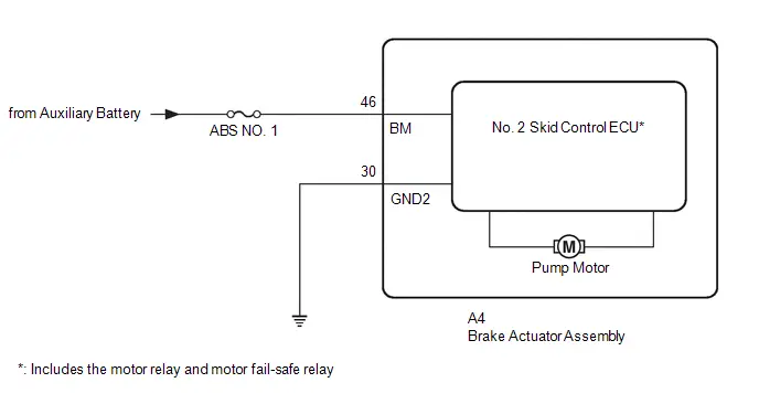
CAUTION / NOTICE / HINT
NOTICE:
Inspect the fuses for circuits related to this system before performing the following procedure.
PROCEDURE
| 1. | CHECK HARNESS AND CONNECTOR (BM TERMINAL) |
Procedure1
(a) Make sure that there is no looseness at the locking part and the connecting part of the connectors.
OK:
The connector is securely connected.
Pre-procedure1
(b) Disconnect the A4 No. 2 skid control ECU (brake actuator assembly) connector.
Procedure2
(c) Check both the connector case and the terminals for deformation and corrosion.
OK:
No deformation or corrosion.
Procedure3
(d) Measure the voltage according to the value(s) in the table below.
Standard Voltage:
 Click Location & Routing(A4) Click Connector(A4)
 | Tester Connection | Condition | Specified Condition | Result |
|---|---|---|---|
| A4-46 (BM) - Body ground | Always | 11 to 14 V | V |
Post-procedure1
(e) None
| NG |

| REPAIR OR REPLACE HARNESS OR CONNECTOR |
|

| 2. | CHECK HARNESS AND CONNECTOR (GND2 TERMINAL) |
(a) Measure the resistance according to the value(s) in the table below.
Standard Resistance:
 Click Location & Routing(A4) Click Connector(A4)
 | Tester Connection | Condition | Specified Condition | Result |
|---|---|---|---|
| A4-30 (GND2) - Body ground | 1 minute or more after disconnecting the cable from the negative (-) auxiliary battery terminal | Below 1 Ω | Ω |
| NG |

| REPAIR OR REPLACE HARNESS OR CONNECTOR |
|

| 3. | CLEAR DTC |
Pre-procedure1
(a) Reconnect the A4 No. 2 skid control ECU (brake actuator assembly) connector.
Procedure1
(b) Clear the DTCs.
Chassis > Brake/EPB > Clear DTCsPost-procedure1
(c) Turn the ignition switch off.
|

| 4. | RECONFIRM DTC |
Pre-procedure1
(a) Based on the Freeze Frame Data and interview with the customer, attempt to reproduce the conditions when the malfunction occurred.
Procedure1
(b) Check if the same DTC is output.
Chassis > Brake/EPB > Trouble CodesHINT:
- If a speed signal of 20 km/h (12 mph) or more is sent to the No. 2 skid control ECU (brake actuator assembly) with the ignition switch turned to ON and the stop light switch assembly off, the ECU performs self-diagnosis of the motor circuit.
- If the normal system code is output (no DTCs are output), slightly jiggle the connectors, wire harness, and fuses of the No. 2 skid control ECU (brake actuator assembly).
- If any DTCs are output while jiggling a connector or wire harness of the No. 2 skid control ECU (brake actuator assembly), inspect and repair the connector or wire harness.
- If no DTCs were output when reconfirming DTCs, checking for intermittent problems is necessary because it is suspected that the original DTCs were stored due to the poor connection of a connector terminal.
| Result | Proceed to |
|---|---|
| C052C14, C052C16, C052C17, C052C49 and C052F14 are not output | A |
| C052C14, C052C16, C052C17, C052C49 or C052F14 is output | B |
Post-procedure1
(c) None
| A |

| USE SIMULATION METHOD TO CHECK |
| B |

| REPLACE BRAKE ACTUATOR ASSEMBLY
|


Brake Pressure Sensor "A" Circuit Voltage Below Threshold (C054016,...,C122D17)
DESCRIPTION
HINT:
Brake pressure sensor "A": Master cylinder pressure sensor
| DTC No. | Detection Item | DTC Detection Condition | Trouble Area | MIL | DTC Output from | Priority | Note |
|---|---|---|---|---|---|---|---|
| C054016 | Brake Pressure Sensor "A" Circuit Voltage Below Threshold | Master cylinder pressure value is below -0.744 MPa (-7.6 kgf/cm2, -107 psi) for 5 seconds or more. | No. 2 skid control ECU (brake actuator assembly) | Comes on | Brake/EPB | A |
|
| C05401F | Brake Pressure Sensor "A" Circuit Intermittent | Fluctuation of the sensor signal exceeds the threshold (15 MPa (153.0 kgf/cm2, 2175 psi) or more from the previous value) for 0.1 seconds or more. | No. 2 skid control ECU (brake actuator assembly) | Comes on | Brake/EPB | A |
|
| C054029 | Brake Pressure Sensor "A" Signal Invalid | Data from the sensor is invalid for 0.2 seconds or more. | No. 2 skid control ECU (brake actuator assembly) | Comes on | Brake/EPB | A |
|
| C054031 | Brake Pressure Sensor "A" No Signal | Communication with the sensor is invalid for 0.1 seconds or more. | No. 2 skid control ECU (brake actuator assembly) | Comes on | Brake/EPB | A |
|
| C054096 | Brake Pressure Sensor "A" Component Internal Failure | A malfunction is detected by self-diagnosis function of the sensor. | No. 2 skid control ECU (brake actuator assembly) | Comes on | Brake/EPB | A |
|
| C122D16 | Brake Pressure Sensor "A" Supply Voltage Circuit Voltage Below Threshold | The supplied voltage to the sensor is less than a certain value for 1 second or more. | No. 2 skid control ECU (brake actuator assembly) | Comes on | Brake/EPB | A |
|
| C122D17 | Brake Pressure Sensor "A" Supply Voltage Circuit Voltage Above Threshold | The supplied voltage to the sensor is a certain value or more for 1 second or more. | No. 2 skid control ECU (brake actuator assembly) | Comes on | Brake/EPB | A |
|
MONITOR DESCRIPTION
- When no abnormal pressure value is output and the master cylinder pressure sensor output is less than a certain value, the No. 2 skid control ECU (brake actuator assembly) judges that the master cylinder pressure sensor zero point is abnormal, the MIL is illuminated and a DTC is stored.
- When an invalid serial communication signal is detected, the No. 2 skid control ECU (brake actuator assembly) judges that communication is abnormal and illuminates the MIL and stores this DTC.
- When the pressure or temperature of a master cylinder pressure sensor exceeds a certain value, the No. 2 skid control ECU (brake actuator assembly) judges that the internal data is abnormal and illuminates the MIL and stores this DTC.
- When the master cylinder pressure sensor data is invalid, the No. 2 skid control ECU (brake actuator assembly) judges that the sensor is invalid, the MIL is illuminated and a DTC is stored.
- When the master cylinder pressure sensor is normal, the difference between the previous value and current value exceeds a certain value, the No. 2 skid control ECU (brake actuator assembly) judges that there is sensor noise, the MIL is illuminated and a DTC is stored.
- When the supply voltage of the master cylinder pressure sensor is a certain value or less, the No. 2 skid control ECU (brake actuator assembly) judges that the power supply voltage of sensor is excessively low, the MIL is illuminated and a DTC is stored.
-
If any of the following conditions are met for a certain amount of time, the No. 2 skid control ECU (brake actuator assembly) judges that the power supply voltage of sensor is excessively high, and illuminates the MIL and stores this DTC.
- The power supply voltage of the master cylinder pressure sensor is more than a certain value.
- The temperature of the master cylinder pressure sensor is more than a certain value.
- The supply current of the master cylinder pressure sensor is more than a certain value.
MONITOR STRATEGY
| Related DTCs | C053D (Case 2): Master cylinder pressure sensor exceeded learning limit C0540 (Case 1): Pressure sensor lost communication C0540 (Case 2): Pressure sensor internal check C0540 (Case 3): Pressure sensor invalid data C056B: Pressure sensor intermittent/erratic C122E: Pressure sensor voltage circuit low C122F: Pressure sensor voltage circuit high |
| Required Sensors/Components(Main) | No. 2 skid control ECU (brake actuator assembly) |
| Required Sensors/Components(Related) | No. 2 skid control ECU (brake actuator assembly) |
| Frequency of Operation | Continuous |
| Duration | 0.084 seconds: C0540 (Case 1) 0.096 seconds: C0540 (Case 2) and C056B 0.198 seconds: C0540 (Case 3) 1 second: C122E and C122F 5 seconds: C053D (Case 2) |
| MIL Operation | Immediately |
| Sequence of Operation | None |
TYPICAL ENABLING CONDITIONS
C053D (Case 2)| Monitor runs whenever the following DTCs are not stored | C0540 (Case 1): Pressure sensor lost communication C0540 (Case 2): Pressure sensor internal check C0540 (Case 3): Pressure sensor invalid data C056B: Pressure sensor intermittent/erratic C122E: Pressure sensor voltage circuit low C122F: Pressure sensor voltage circuit high |
| Monitor runs whenever the following DTCs are not stored | C122E: Pressure sensor voltage circuit low C122F: Pressure sensor voltage circuit high |
| Both of the following conditions are met | - |
| Master cylinder pressure sensor power supply | Valid |
| Master cylinder pressure sensor power supply voltage low signal (IC Data) | Off |
| Monitor runs whenever the following DTCs are not stored | C0540 (Case 1): Pressure sensor lost communication C122E: Pressure sensor voltage circuit low C122F: Pressure sensor voltage circuit high |
| All of the following conditions are met | - |
| Communication with master cylinder pressure sensor | Valid |
| Master cylinder pressure sensor power supply | Valid |
| Master cylinder pressure sensor power supply voltage low signal (IC Data) | Off |
| Monitor runs whenever the following DTCs are not stored | C0540 (Case 1): Pressure sensor lost communication C0540 (Case 2): Pressure sensor internal check C0540 (Case 3): Pressure sensor invalid data C056B: Pressure sensor intermittent/erratic C122E: Pressure sensor voltage circuit low C122F: Pressure sensor voltage circuit high |
| All of the following conditions are met | A, B, C, D, E, F, G and H |
| A. Following condition is met | More than 0.22 seconds |
| BS voltage | 8.5 V or higher |
| B. Master cylinder pressure sensor power supply voltage low signal (IC Data) | Off |
| C. Master cylinder pressure sensor power supply voltage high signal (IC Data) | Off |
| D. Master cylinder pressure sensor overtemperature signal (IC Data) | Off |
| E. Master cylinder pressure sensor overcurrent signal (IC Data) | Off |
| F. BS voltage | 9.5 V or higher |
| G. IGR voltage | Higher than 10 V |
| H. IGP voltage | Higher than 10 V |
| Monitor runs whenever the following DTCs are not stored | C0540 (Case 1): Pressure sensor lost communication C122E: Pressure sensor voltage circuit low C122F: Pressure sensor voltage circuit high |
| All of the following conditions are met | - |
| Communication with master cylinder pressure sensor | Valid |
| Master cylinder pressure sensor power supply | Valid |
| Master cylinder pressure sensor power supply voltage low signal (IC Data) | Off |
| Master cylinder pressure sensor power supply voltage high signal (IC Data) | Off |
| Monitor runs whenever the following DTCs are not stored | C122E: Pressure sensor voltage circuit low |
| All of the following conditions are met | A, B, C, D, E, F, G and H |
| A. Following condition is met | More than 0.22 seconds |
| BS voltage | 8.5 V or higher |
| B. Master cylinder pressure sensor overcurrent signal (IC Data) | Off |
| C. Master cylinder pressure sensor overtemperature signal (IC Data) | Off |
| D. BS voltage | 9.5 V or higher |
| E. IGR voltage | Higher than 10 V |
| F. IGP voltage | Higher than 10 V |
| Master cylinder pressure sensor power supply output | On |
TYPICAL MALFUNCTION THRESHOLDS
C053D (Case 2)| Master cylinder pressure sensor | Higher than 1.764 MPa (18.0 kgf/cm2, 256 psi) |
| Communication with master cylinder pressure sensor | Invalid |
| Either of the following conditions is met | - |
| Master cylinder pressure sensor value | Higher than 23.328 MPa (237.9 kgf/cm2, 3383 psi) |
| Master cylinder pressure sensor temp value | Higher than 150°C (302°F) |
| Either of the following conditions is met | - |
| Master cylinder pressure sensor power supply | Invalid |
| Communication with master cylinder pressure sensor | Invalid |
| Absolute value of the change in master cylinder pressure sensor value during 6millisec | Higher than 15 MPa (153.0 kgf/cm2, 2175 psi) |
| Master cylinder pressure sensor temp value | Higher than 150°C (302°F) |
| Master cylinder pressure sensor value | Higher than 23.328 MPa (237.9 kgf/cm2, 3383 psi) |
| Absolute value of the change in master cylinder pressure sensor value during 6millisec | Higher than 15 MPa (153.0 kgf/cm2, 2175 psi) |
| Master cylinder pressure sensor power supply voltage low signal (IC Data) | On |
| Either of the following conditions is met | - |
| Master cylinder pressure sensor power supply voltage high signal (IC Data) | On |
| Master cylinder pressure sensor overcurrent signal (IC Data) | On |
| Master cylinder pressure sensor overtemperature signal (IC Data) | On |
COMPONENT OPERATING RANGE
C053D (Case 2)| Both of the following conditions are met | - |
| Pressure sensor fail (C0540,C122E,C122F,C056B) | Not detected |
| Master cylinder pressure sensor | -0.744 MPa (-7.6 kgf/cm2, -107 psi) or higher |
| Communication with master cylinder pressure sensor | Valid |
| All of the following conditions are met | - |
| Communication with master cylinder pressure sensor | Valid |
| Master cylinder pressure sensor value | 23.328 MPa (237.9 kgf/cm2, 3383 psi) or less |
| Master cylinder pressure sensor temp value | 150°C (302°F) or less |
| All of the following conditions are met | A, B, C, D, E and F |
| A. Following condition is met | More than 0.22 seconds |
| BS voltage | 8.5 V or higher |
| B. Master cylinder pressure sensor power supply voltage low signal (IC Data) | Off |
| C. Master cylinder pressure sensor power supply voltage high signal (IC Data) | Off |
| D. Master cylinder pressure sensor overtemperature signal (IC Data) | Off |
| E. Master cylinder pressure sensor overcurrent signal (IC Data | Off |
| F. All of the following conditions are met | More than 0.024 seconds |
| Master cylinder pressure sensor power supply | Valid |
| Communication with master cylinder pressure sensor | Valid |
| Absolute value of the change in master cylinder pressure sensor value during 6millisec | 15 MPa (153.0 kgf/cm2, 2175 psi) or less |
| Master cylinder pressure sensor temp value | 150°C (302°F) or less |
| Master cylinder pressure sensor value | 23.328 MPa (237.9 kgf/cm2, 3383 psi) or less |
| All of the following conditions are met | - |
| Communication with master cylinder pressure sensor | Valid |
| Master cylinder pressure sensor power supply | Valid |
| Master cylinder pressure sensor power supply voltage low signal (IC Data) | Off |
| Master cylinder pressure sensor power supply voltage high signal (IC Data) | Off |
| Absolute value of the change in Master cylinder pressure sensor value during 6millisec | 15 MPa (153.0 kgf/cm2, 2175 psi) or less |
| All of the following conditions are met | - |
| Master cylinder pressure sensor power supply | Valid |
| Master cylinder pressure sensor power supply voltage high signal (IC Data) | Off |
| Master cylinder pressure sensor power supply voltage low signal (IC Data) | Off |
| Master cylinder pressure sensor overcurrent signal (IC Data) | Off |
| Master cylinder pressure sensor overtemperature signal (IC Data) | Off |
CONFIRMATION DRIVING PATTERN
NOTICE:
When performing the normal judgment procedure, make sure that the driver door is closed and is not opened at any time during the procedure.
HINT:
- After repair has been completed, clear the DTC and then check that the Toyota Prius vehicle has returned to normal by performing the following All Readiness check procedure.
- When clearing the permanent DTCs, refer to the "CLEAR PERMANENT DTC" procedure.
- Connect the GTS to the DLC3.
- Turn the ignition switch to ON and turn the GTS on.
- Clear the DTCs (even if no DTCs are stored, perform the clear DTC procedure).
- Turn the ignition switch off.
- Turn the ignition switch to ON (READY) and turn the GTS on.
- Drive the Toyota Prius vehicle at a speed of 20 km/h (12 mph) for 1 minute. [*1]
-
Operate the ABS using a drum tester or equivalent. [*2]
HINT:
[*1] to [*2]: Normal judgment procedure.
The normal judgment procedure is used to complete DTC judgment and also used when clearing permanent DTCs.
-
Enter the following menus: Chassis / Brake/EPB* / Utility / All Readiness.
*: Electric Parking Brake System
-
Check the DTC judgment result.
HINT:
- If the judgment result shows NORMAL, the system is normal.
- If the judgment result shows ABNORMAL, the system has a malfunction.
- If the judgment result shows INCOMPLETE, perform driving pattern again.
PROCEDURE
| 1. | REPLACE BRAKE ACTUATOR ASSEMBLY |
HINT:
Click here


| NEXT |

| END |
Brake Pressure Sensor "A" Circuit Voltage Above Threshold (C054017)
DESCRIPTION
HINT:
Brake pressure sensor "A": Master cylinder pressure sensor
| DTC No. | Detection Item | DTC Detection Condition | Trouble Area | MIL | DTC Output from | Priority | Note |
|---|---|---|---|---|---|---|---|
| C054017 | Brake Pressure Sensor "A" Circuit Voltage Above Threshold | When the brake pedal is not depressed, master cylinder pressure continuously exceeds 1.764 MPa (18.0 kgf/cm2, 256 psi) for 5 seconds or more. | No. 2 skid control ECU (brake actuator assembly) | Comes on | Brake/EPB | A |
|
MONITOR DESCRIPTION
When the value of the master cylinder pressure sensor is more than a certain value for a certain amount of time, the No. 2 skid control ECU (brake actuator assembly) judges that the master cylinder pressure sensor zero point is abnormal, and illuminates the MIL and stores this DTC.
MONITOR STRATEGY
| Related DTCs | C053D (Case 1): Master cylinder pressure sensor exceeded learning limit |
| Required Sensors/Components(Main) | No. 2 skid control ECU (brake actuator assembly) |
| Required Sensors/Components(Related) | No. 2 skid control ECU (brake actuator assembly) |
| Frequency of Operation | Continuous |
| Duration | 5 seconds |
| MIL Operation | Immediately |
| Sequence of Operation | None |
TYPICAL ENABLING CONDITIONS
| Monitor runs whenever the following DTCs are not stored | C0540 (Case 1): Pressure sensor lost communication C0540 (Case 2): Pressure sensor internal check C0540 (Case 3): Pressure sensor invalid data C056B: Pressure sensor intermittent/erratic C1103 (Case 1): Brake pedal position sensor voltage circuit open C1103 (Case 2): Brake pedal position sensor invalid data C122E: Pressure sensor voltage circuit low C122F: Pressure sensor voltage circuit high P057A: Brake pedal position sensor invalid data P05DB: Brake pedal position sensor invalid data P05DD: Brake pedal position sensor circuit open P05DE: Brake pedal position sensor circuit high P05DF: Brake pedal position sensor intermittent/erratic P05E0: Brake pedal position sensor "A"/"B" correlation |
| Either of the following conditions is met | A and B |
| A. Both of the following conditions are met | - |
| Up / downstream communication | Valid |
| Zero point error permission | On |
| B. All of the following conditions are met | - |
| Up / downstream communication | Invalid |
| Brake position sensor circuit effective invalidity | Valid |
| Brake actuator operation | Off |
TYPICAL MALFUNCTION THRESHOLDS
| Master cylinder pressure sensor | Higher than 1.764 MPa (18.0 kgf/cm2, 256 psi) |
COMPONENT OPERATING RANGE
| All of the following conditions are met | A, B, C and D |
| A. Pressure sensor fail (C0540, C122E, C122F, C056B) | Not detected |
| B. Brake pedal position sensor fail (C1103, P057A, P05DB, P05DD, P05DE, P05DF, P05E0) | Not detected |
| C. Either of the following conditions is met | a or b |
| a. Both of the following conditions are met | - |
| Up / downstream communication | Valid |
| Zero point error permission | On |
| b. All of the following conditions are met | - |
| Up / downstream communication | Invalid |
| Brake position sensor circuit effective invalidity | Valid |
| Brake actuator operation | Off |
| D. Master cylinder pressure sensor | 1.764 MPa (18.0 kgf/cm2, 256 psi) or less |
CONFIRMATION DRIVING PATTERN
NOTICE:
When performing the normal judgment procedure, make sure that the driver door is closed and is not opened at any time during the procedure.
HINT:
- After repair has been completed, clear the DTC and then check that the Toyota Prius vehicle has returned to normal by performing the following All Readiness check procedure.
- When clearing the permanent DTCs, refer to the "CLEAR PERMANENT DTC" procedure.
- Connect the GTS to the DLC3.
- Turn the ignition switch to ON and turn the GTS on.
- Clear the DTCs (even if no DTCs are stored, perform the clear DTC procedure).
- Turn the ignition switch off.
- Turn the ignition switch to ON (READY) and turn the GTS on.
- Drive the Toyota Prius vehicle at a speed of 20 km/h (12 mph) for 1 minute. [*1]
-
Operate the ABS using a drum tester or equivalent. [*2]
HINT:
[*1] to [*2]: Normal judgment procedure.
The normal judgment procedure is used to complete DTC judgment and also used when clearing permanent DTCs.
-
Enter the following menus: Chassis / Brake/EPB* / Utility / All Readiness.
*: Electric Parking Brake System
-
Check the DTC judgment result.
HINT:
- If the judgment result shows NORMAL, the system is normal.
- If the judgment result shows ABNORMAL, the system has a malfunction.
- If the judgment result shows INCOMPLETE, perform driving pattern again.
PROCEDURE
| 1. | CHECK BRAKE PEDAL |
(a) Check that the brake pedal and the brake pedal stroke sensor assembly are properly installed and that the pedal can be depressed normally.
(b) Check and adjust the brake pedal height.
HINT:
Click here

(c) Adjust the brake pedal stroke sensor assembly.
HINT:
Click here

|

| 2. | READ VALUE USING GTS (MASTER CYLINDER SENSOR 1) |
(a) Check that the master cylinder pressure sensor output value is within -1.00 to 0.00 MPa when the brake pedal is not depressed.
Chassis > Brake/EPB > Data List| Tester Display | Measurement Item | Range | Normal Condition | Diagnostic Note |
|---|---|---|---|---|
| Master Cylinder Sensor 1 | Master cylinder pressure sensor pressure (value detected by ECU) | Min.: -1.00 MPa Max.: 23.99 MPa | Brake pedal released: -1.00 to 0.00 MPa | Reading increases when brake pedal is depressed |
| Tester Display |
|---|
| Master Cylinder Sensor 1 |
| Result | Proceed to |
|---|---|
| The value of Master Cylinder Sensor 1 is between -1.00 and 0.00 MPa | A |
| None of the above conditions are met | B |
| B |

| REPLACE BRAKE ACTUATOR ASSEMBLY
|


|

| 3. | CLEAR DTC |
Pre-procedure1
(a) None
Procedure1
(b) Clear the DTCs.
Chassis > Brake/EPB > Clear DTCsPost-procedure1
(c) Turn the ignition switch off.
|

| 4. | RECONFIRM DTC |
Pre-procedure1
(a) Based on the Freeze Frame Data and interview with the customer, attempt to reproduce the conditions when the malfunction occurred.
Procedure1
(b) Check if the same DTC is output.
Chassis > Brake/EPB > Trouble Codes| Result | Proceed to |
|---|---|
| C054017 is not output | A |
| C054017 is output | B |
Post-procedure1
(c) None
| A |

| USE SIMULATION METHOD TO CHECK |
| B |

| REPLACE BRAKE ACTUATOR ASSEMBLY
|


Left Front Wheel Speed Sensor Incorrect Component Installed (C055595)
DESCRIPTION
| DTC No. | Detection Item | DTC Detection Condition | Trouble Area | MIL | DTC Output from | Priority | Note |
|---|---|---|---|---|---|---|---|
| C055595 | Left Front Wheel Speed Sensor Incorrect Component Installed | History of front speed sensor LH being installed incorrectly | Front speed sensor LH | Comes on | Brake/EPB | A |
|
MONITOR DESCRIPTION
The No. 2 skid control ECU (brake actuator assembly) monitors the output of the speed sensor. When the wrong installation of the speed sensor is detected, the MIL is illuminated and a DTC is stored.
MONITOR STRATEGY
| Related DTCs | C0555: Wheel speed sensor (FL) range/performance |
| Required Sensors/Components(Main) | Speed sensor Speed sensor rotor |
| Required Sensors/Components(Related) | No. 2 skid control ECU (brake actuator assembly) |
| Frequency of Operation | Continuous |
| Duration | 5 times |
| MIL Operation | Immediately |
| Sequence of Operation | None |
TYPICAL ENABLING CONDITIONS
| Monitor runs whenever the following DTCs are not stored | C0501 (Case 4): Wheel speed sensor (FL) range/performance (pulse output high) C0502: Wheel speed sensor (FL) voltage circuit open C0503: Wheel speed sensor (FL) voltage circuit high C0507 (Case 4): Wheel speed sensor (FR) range/performance (pulse output high) C0508: Wheel speed sensor (FR) voltage circuit open C0509: Wheel speed sensor (FR) voltage circuit high C050D (Case 4): Wheel speed sensor (RL) range/performance (pulse output high) C050E: Wheel speed sensor (RL) voltage circuit open C050F: Wheel speed sensor (RL) voltage circuit high C0513 (Case 4): Wheel speed sensor (RR) range/performance (pulse output high) C0514: Wheel speed sensor (RR) voltage circuit open C0515: Wheel speed sensor (RR) voltage circuit high C137D: Brake system voltage circuit high C14E1 (Case 1): Wheel speed sensor (FL) voltage circuit low C14E1 (Case 2): Wheel speed sensor (FL) voltage circuit low (continuation) C14E4 (Case 1): Wheel speed sensor (FR) voltage circuit low C14E4 (Case 2): Wheel speed sensor (FR) voltage circuit low (continuation) C14E7 (Case 1): Wheel speed sensor (RL) voltage circuit low C14E7 (Case 2): Wheel speed sensor (RL) voltage circuit low (continuation) C14EA (Case 1): Wheel speed sensor (RR) voltage circuit low C14EA (Case 2): Wheel speed sensor (RR) voltage circuit low (continuation) |
| All of the following conditions are met | A, B, C, D, E, F and G |
| A. Wheel speed sensor open circuit signal (IC Data) | Off |
| B. Wheel speed sensor power supply voltage low signal (IC Data) | Off |
| C. Following condition is met | More than 0.22 seconds |
| BS voltage | 9.5 V or higher |
| D. Following condition is met | More than 0.22 seconds |
| BS voltage | 17.4 V or less |
| E. Wheel speed sensor pulse | Exist |
| F. IGR voltage | Higher than 10 V |
| G. IGP voltage | Higher than 10 V |
TYPICAL MALFUNCTION THRESHOLDS
| Wheel speed sensor overcurrent state (IC Data) | On |
COMPONENT OPERATING RANGE
| All of the following conditions are met | A, B, C, D, E, F, G, H and I |
| A. Wheel speed sensor open circuit signal (IC Data) | Off |
| B. Wheel speed sensor power supply voltage low signal (IC Data) | Off |
| C. Following condition is met | More than 0.22 seconds |
| BS voltage | 9.5 V or higher |
| D. Following condition is met | More than 0.22 seconds |
| BS voltage | 17.4 V or less |
| E. Wheel speed sensor pulse | Exist |
| F. Wheel speed sensor fail (C0502, C0503, C0508, C0509, C050E, C050F, C0514, C0515, C14E1, C14E4, C14E7, C14EA) | Not detected |
| G. Wheel speed sensor range/performance (pulse output high) fail (C0501, C0507, C050D, C0513) | Not detected |
| H. Speed sensor output value | 10 km/h (6.21 mph) or more |
| I. Wheel speed sensor overcurrent state (IC Data) | Off |
CONFIRMATION DRIVING PATTERN
NOTICE:
When performing the normal judgment procedure, make sure that the driver door is closed and is not opened at any time during the procedure.
HINT:
- After repair has been completed, clear the DTC and then check that the Toyota Prius vehicle has returned to normal by performing the following All Readiness check procedure.
- When clearing the permanent DTCs, refer to the "CLEAR PERMANENT DTC" procedure.
- Connect the GTS to the DLC3.
- Turn the ignition switch to ON and turn the GTS on.
- Clear the DTCs (even if no DTCs are stored, perform the clear DTC procedure).
- Turn the ignition switch off.
- Turn the ignition switch to ON (READY) and turn the GTS on.
-
Drive the Toyota Prius vehicle straight at a speed of 20 km/h (12 mph) or more for 10 seconds or more. [*]
HINT:
[*]: Normal judgment procedure.
The normal judgment procedure is used to complete DTC judgment and also used when clearing permanent DTCs.
-
Enter the following menus: Chassis / Brake/EPB* / Utility / All Readiness.
*: Electric Parking Brake System
-
Check the DTC judgment result.
HINT:
- If the judgment result shows NORMAL, the system is normal.
- If the judgment result shows ABNORMAL, the system has a malfunction.
- If the judgment result shows INCOMPLETE, perform driving pattern again.
PROCEDURE
| 1. | CHECK PART NUMBER (FRONT SPEED SENSOR LH) |
(a) Check that the front speed sensor LH is installed.
OK:
Proper front speed sensor LH is installed.
NOTICE:
If it is necessary to remove components in order to check the front speed sensor LH, follow the relevant installation and removal procedures and precautions for those components.
| NG |

| REPLACE FRONT SPEED SENSOR LH |
|

| 2. | CLEAR DTC |
Pre-procedure1
(a) None
Procedure1
(b) Clear the DTCs.
Chassis > Brake/EPB > Clear DTCsPost-procedure1
(c) Turn the ignition switch off.
|

| 3. | RECONFIRM DTC |
Pre-procedure1
(a) Based on the Freeze Frame Data and interview with the customer, attempt to reproduce the conditions when the malfunction occurred.
Procedure1
(b) Check if the same DTC is output.
Chassis > Brake/EPB > Trouble Codes| Result | Proceed to |
|---|---|
| C055595 is not output | A |
| C055595 is output | B |
Post-procedure1
(c) None
| A |

| USE SIMULATION METHOD TO CHECK |
| B |

| REPLACE FRONT SPEED SENSOR LH |
Brake System Control Module "A" Internal Electronic Failure (C059749,C12F662,C12F762,C13BF62)
DESCRIPTION
The solenoid relay and solenoid valves are built into the brake actuator assembly.
The solenoid valves control the brake fluid pressure at each wheel cylinder.
When these DTCs are stored, the fail-safe function operates and the solenoid relay is turned off to prevent the solenoid valves from operating.
HINT:
- Brake pressure control solenoid "A": Solenoid SM1
- Brake pressure control solenoid "B": Solenoid SM2
| DTC No. | Detection Item | DTC Detection Condition | Trouble Area | MIL | DTC Output from | Priority | Note |
|---|---|---|---|---|---|---|---|
| C059749 | Brake System Control Module "A" Internal Electronic Failure | When the BS terminal voltage is from 9.5 to 17.4 V and the solenoid relay is ON, the relay contact is ON and the pump motor is in a low voltage state continuously for 0.1 seconds or more. | No. 2 skid control ECU (brake actuator assembly) | Comes on | Brake/EPB | A |
|
| C12F662 | Left Front Wheel ABS Hold Solenoid / Right Front Wheel ABS Hold Solenoid Signal Compare Failure | A difference in holding solenoid (SFLH) and holding solenoid (SFRH) output accuracy continues for 0.2 seconds or more. | No. 2 skid control ECU (brake actuator assembly) | Comes on | Brake/EPB | A |
|
| C12F762 | Left Rear Wheel ABS Hold Solenoid / Right Rear Wheel ABS Hold Solenoid Signal Compare Failure | A difference in holding solenoid (SRLH) and holding solenoid (SRRH) output accuracy continues for 0.2 seconds or more. | No. 2 skid control ECU (brake actuator assembly) | Comes on | Brake/EPB | A |
|
| C13BF62 | Brake Pressure Control Solenoid "A" / "B" Signal Compare Failure | A difference in master cylinder cut solenoid (SM1) and master cylinder cut solenoid (SM2) output accuracy continues for 0.2 seconds or more. | No. 2 skid control ECU (brake actuator assembly) | Comes on | Brake/EPB | A |
|
MONITOR DESCRIPTION
- The No. 2 skid control ECU (brake actuator assembly) monitors the solenoid circuit and when an abnormal monitor value is detected, the MIL is illuminated and a DTC is stored.
-
The No. 2 skid control ECU (brake actuator assembly) monitors the drive voltage and current of the ABS holding solenoid and master cylinder cut solenoid. Based on the monitored information, if any of the following abnormal conditions are detected, the MIL is illuminated and a DTC is stored.
- A difference in output accuracy of the ABS holding solenoid (SFLH) and ABS holding solenoid (SFRH) is detected.
- A difference in output accuracy of the ABS holding solenoid (SRLH) and ABS holding solenoid (SRRH) is detected.
- A difference in output accuracy of the Master cylinder cut solenoid (SM1) and master cylinder cut solenoid (SM2) is detected.
MONITOR STRATEGY
| Related DTCs | C0597 (Case 1): ABS hold solenoid circuit stuck C0597 (Case 2 to 5): ABS hold solenoid performance C12F6: ABS hold solenoid other functional C12F7: ABS hold solenoid other functional C13BF: SM solenoid other functional |
| Required Sensors/Components(Main) | No. 2 skid control ECU (brake actuator assembly) |
| Required Sensors/Components(Related) | No. 2 skid control ECU (brake actuator assembly) |
| Frequency of Operation | Continuous |
| Duration | 0.012 seconds: C0597 (Case 2 and 5) 0.054 seconds: C0597 (Case 3 and 4) 0.102 seconds: C0597 (Case 1) 0.198 seconds: C12F6, C12F7 and C13BF |
| MIL Operation | Immediately |
| Sequence of Operation | None |
TYPICAL ENABLING CONDITIONS
C0597 (Case 1)| Monitor runs whenever the following DTCs are not stored | C12A7 (Case 1 and 2): ABS hold solenoid (FL) circuit open C12A7 (Case 3): ABS hold solenoid (FL) circuit low C12A8 (Case 1): ABS hold solenoid (FL) circuit high (solenoid Off current) C12A8 (Case 2 and 3): ABS hold solenoid (FL) circuit high (IC data) C12A8 (Case 4): ABS hold solenoid (FL) circuit high (solenoid On current) C12B2: ABS release solenoid (FL) circuit low C12B3: ABS release solenoid (FL) circuit high C12BD (Case 1 and 2): ABS hold solenoid (FR) circuit open C12BD (Case 3): ABS hold solenoid (FR) circuit low C12BE (Case 1): ABS hold solenoid (FR) circuit high (solenoid Off current) C12BE (Case 2 and 3): ABS hold solenoid (FR) circuit high (IC data) C12BE (Case 4): ABS hold solenoid (FR) circuit high (solenoid On current) C12C8: ABS release solenoid (FR) circuit low C12C9: ABS release solenoid (FR) circuit high C12D3 (Case 1 and 2): ABS hold solenoid (RL) circuit open C12D3 (Case 3): ABS hold solenoid (RL) circuit low C12D4 (Case 1): ABS hold solenoid (RL) circuit high (solenoid Off current) C12D4 (Case 2 and 3): ABS hold solenoid (RL) circuit high (IC data) C12D4 (Case 4): ABS hold solenoid (RL) circuit high (solenoid On current) C12DE: ABS release solenoid (RL) circuit low C12DF: ABS release solenoid (RL) circuit high C12E9 (Case 1 and 2): ABS hold solenoid (RR) circuit open C12E9 (Case 3): ABS hold solenoid (RR) circuit low C12EA (Case 1): ABS hold solenoid (RR) circuit high (solenoid Off current) C12EA (Case 2 and 3): ABS hold solenoid (RR) circuit high (IC data) C12EA (Case 4): ABS hold solenoid (RR) circuit high (solenoid On current) C12F4: ABS release solenoid (RR) circuit low C12F5: ABS release solenoid (RR) circuit high C12F6: ABS hold solenoid other functional C12F7: ABS hold solenoid other functional C137D: Brake system voltage circuit high C13BF: SM solenoid other functional C13C2 (Case 1 and 2): SM1 solenoid circuit open C13C2 (Case 3): SM1 solenoid circuit low C13C3 (Case 1): SM1 solenoid circuit high (solenoid Off current) C13C3 (Case 2 and 3): SM1 solenoid circuit high (IC data) C13C3 (Case 4): SM1 solenoid circuit high (solenoid On current) C13CB (Case 1 and 2): SM2 solenoid circuit open C13CB (Case 3): SM2 solenoid circuit low C13CC (Case 1): SM2 solenoid circuit high (solenoid Off current) C13CC (Case 2 and 3): SM2 solenoid circuit high (IC data) C13CC (Case 4): SM2 solenoid circuit high (solenoid On current) C143B: Brake system voltage power supply relay circuit high C143C: Brake system voltage power supply relay circuit open |
| All of the following conditions are met | A, B, C, D, E and F |
| A. Command to solenoid relay | On |
| B. Following condition is met | More than 0.012 seconds |
| AST voltage | 6 V or higher |
| C. Following condition is met | More than 0.22 seconds |
| BS voltage | 9.5 V or higher |
| D. Following condition is met | More than 0.22 seconds |
| BS voltage | 17.4 V or less |
| E. IGR voltage | Higher than 10 V |
| F. IGP voltage | Higher than 10 V |
| Monitor runs whenever the following DTCs are not stored | C12A7 (Case 1 and 2): ABS hold solenoid (FL) circuit open C12A8 (Case 1): ABS hold solenoid (FL) circuit high (solenoid Off current) C12B2: ABS release solenoid (FL) circuit low C12B3: ABS release solenoid (FL) circuit high C12BD (Case 1 and 2): ABS hold solenoid (FR) circuit open C12BE (Case 1): ABS hold solenoid (FR) circuit high (solenoid Off current) C12C8: ABS release solenoid (FR) circuit low C12C9: ABS release solenoid (FR) circuit high C12D3 (Case 1 and 2): ABS hold solenoid (RL) circuit open C12D4 (Case 1): ABS hold solenoid (RL) circuit high (solenoid Off current) C12DE: ABS release solenoid (RL) circuit low C12DF: ABS release solenoid (RL) circuit high C12E9 (Case 1 and 2): ABS hold solenoid (RR) circuit open C12EA (Case 1): ABS hold solenoid (RR) circuit high (solenoid Off current) C12F4: ABS release solenoid (RR) circuit low C12F5: ABS release solenoid (RR) circuit high C12F6: ABS hold solenoid other functional C12F7: ABS hold solenoid other functional C137D: Brake system voltage circuit high C13BF: SM solenoid other functional C13C2 (Case 1 and 2): SM1 solenoid circuit open C13C2 (Case 3): SM1 solenoid circuit low C13C3 (Case 1): SM1 solenoid circuit high (solenoid Off current) C13CB (Case 1 and 2): SM2 solenoid circuit open C13CB (Case 3): SM2 solenoid circuit low C13CC (Case 1): SM2 solenoid circuit high (solenoid Off current) C143B: Brake system voltage power supply relay circuit high C143C: Brake system voltage power supply relay circuit open |
| All of the following conditions are met | A, B, C, D, E, F, G and H |
| A. ECU status | Premain |
| B. Following condition is met | More than 0.22 seconds |
| BS voltage | 9.5 V or higher |
| C. Command to solenoid relay | Off |
| D. ASIC output permission | Off |
| E. AST voltage | Higher than 1.3 V |
| F. BS voltage | 9.5 V or higher |
| G. IGR voltage | Higher than 10 V |
| H. IGP voltage | Higher than 10 V |
| Monitor runs whenever the following DTCs are not stored | C12A7 (Case 1 and 2): ABS hold solenoid (FL) circuit open C12A8 (Case 1): ABS hold solenoid (FL) circuit high (solenoid Off current) C12B2: ABS release solenoid (FL) circuit low C12B3: ABS release solenoid (FL) circuit high C12BD (Case 1 and 2): ABS hold solenoid (FR) circuit open C12BE (Case 1): ABS hold solenoid (FR) circuit high (solenoid Off current) C12C8: ABS release solenoid (FR) circuit low C12C9: ABS release solenoid (FR) circuit high C12D3 (Case 1 and 2): ABS hold solenoid (RL) circuit open C12D4 (Case 1): ABS hold solenoid (RL) circuit high (solenoid Off current) C12DE: ABS release solenoid (RL) circuit low C12DF: ABS release solenoid (RL) circuit high C12E9 (Case 1 and 2): ABS hold solenoid (RR) circuit open C12EA (Case 1): ABS hold solenoid (RR) circuit high (solenoid Off current) C12F4: ABS release solenoid (RR) circuit low C12F5: ABS release solenoid (RR) circuit high C12F6: ABS hold solenoid other functional C12F7: ABS hold solenoid other functional C137D: Brake system voltage circuit high C13BF: SM solenoid other functional C13C2 (Case 1 and 2): SM1 solenoid circuit open C13C3 (Case 1): SM1 solenoid circuit high (solenoid Off current) C13CB (Case 1 and 2): SM2 solenoid circuit open C13CC (Case 1): SM2 solenoid circuit high (solenoid Off current) C143B: Brake system voltage power supply relay circuit high C143C: Brake system voltage power supply relay circuit open |
| All of the following conditions are met | A, B, C, D, E, F, G and H |
| A. ECU status | Premain |
| B. Following condition is met | More than 0.22 seconds |
| BS voltage | 9.5 V or higher |
| C. Command to solenoid relay | On |
| D. ASIC output permission | Off |
| E. Solenoid current output order value | 0.16 A |
| F. AST voltage | 6 V or higher |
| G. IGR voltage | Higher than 10 V |
| H. IGP voltage | Higher than 10 V |
| Monitor runs whenever the following DTCs are not stored | C12A7 (Case 1 and 2): ABS hold solenoid (FL) circuit open C12A8 (Case 1): ABS hold solenoid (FL) circuit high (solenoid Off current) C12B2: ABS release solenoid (FL) circuit low C12B3: ABS release solenoid (FL) circuit high C12BD (Case 1 and 2): ABS hold solenoid (FR) circuit open C12BE (Case 1): ABS hold solenoid (FR) circuit high (solenoid Off current) C12C8: ABS release solenoid (FR) circuit low C12C9: ABS release solenoid (FR) circuit high C12D3 (Case 1 and 2): ABS hold solenoid (RL) circuit open C12D4 (Case 1): ABS hold solenoid (RL) circuit high (solenoid Off current) C12DE: ABS release solenoid (RL) circuit low C12DF: ABS release solenoid (RL) circuit high C12E9 (Case 1 and 2): ABS hold solenoid (RR) circuit open C12EA (Case 1): ABS hold solenoid (RR) circuit high (solenoid Off current) C12F4: ABS release solenoid (RR) circuit low C12F5: ABS release solenoid (RR) circuit high C12F6: ABS hold solenoid other functional C12F7: ABS hold solenoid other functional C137D: Brake system voltage circuit high C13BF: SM solenoid other functional C13C2 (Case 1 and 2): SM1 solenoid circuit open C13C3 (Case 1): SM1 solenoid circuit high (solenoid Off current) C13CB (Case 1 and 2): SM2 solenoid circuit open C13CC (Case 1): SM2 solenoid circuit high (solenoid Off current) C143B: Brake system voltage power supply relay circuit high C143C: Brake system voltage power supply relay circuit open |
| All of the following conditions are met | A, B, C, D, E, F, G and H |
| A. ECU status | Premain |
| B. Following condition is met | More than 0.22 seconds |
| BS voltage | 9.5 V or higher |
| C. Command to solenoid relay | On |
| D. ASIC output permission | Off |
| E. Solenoid current output order value | 0.16 A |
| F. Command to NC solenoid | On |
| G. AST voltage | 6 V or higher |
| H. IGR voltage | Higher than 10 V |
| I. IGP voltage | Higher than 10 V |
| Monitor runs whenever the following DTCs are not stored | C12A7 (Case 1 and 2): ABS hold solenoid (FL) circuit open C12A8 (Case 1): ABS hold solenoid (FL) circuit high (solenoid Off current) C12B2: ABS release solenoid (FL) circuit low C12B3: ABS release solenoid (FL) circuit high C12BD (Case 1 and 2): ABS hold solenoid (FR) circuit open C12BE (Case 1): ABS hold solenoid (FR) circuit high (solenoid Off current) C12C8: ABS release solenoid (FR) circuit low C12C9: ABS release solenoid (FR) circuit high C12D3 (Case 1 and 2): ABS hold solenoid (RL) circuit open C12D4 (Case 1): ABS hold solenoid (RL) circuit high (solenoid Off current) C12DE: ABS release solenoid (RL) circuit low C12DF: ABS release solenoid (RL) circuit high C12E9 (Case 1 and 2): ABS hold solenoid (RR) circuit open C12EA (Case 1): ABS hold solenoid (RR) circuit high (solenoid Off current) C12F4: ABS release solenoid (RR) circuit low C12F5: ABS release solenoid (RR) circuit high C12F6: ABS hold solenoid other functional C12F7: ABS hold solenoid other functional C137D: Brake system voltage circuit high C13BF: SM solenoid other functional C13C2 (Case 1 and 2): SM1 solenoid circuit open C13C3 (Case 1): SM1 solenoid circuit high (solenoid Off current) C13CB (Case 1 and 2): SM2 solenoid circuit open C13CC (Case 1): SM2 solenoid circuit high (solenoid Off current) C143B: Brake system voltage power supply relay circuit high C143C: Brake system voltage power supply relay circuit open |
| All of the following conditions are met | - |
| ECU status | Premain |
| Command to solenoid relay | Off |
| ASIC output permission | Off |
| ASIC QA answer | NG answer |
| BS voltage | 9.5 V or higher |
| IGR voltage | Higher than 10 V |
| IGP voltage | Higher than 10 V |
| Monitor runs whenever the following DTCs are not stored | C0597: ABS hold solenoid performance C12A7 (Case 1 and 2): ABS hold solenoid (FL) circuit open C12A7 (Case 3): ABS hold solenoid (FL) circuit low C12A8 (Case 1): ABS hold solenoid (FL) circuit high (solenoid Off current) C12A8 (Case 2 and 3): ABS hold solenoid (FL) circuit high (IC data) C12A8 (Case 4): ABS hold solenoid (FL) circuit high (solenoid On current) C12B2: ABS release solenoid (FL) circuit low C12B3: ABS release solenoid (FL) circuit high C12BD (Case 1 and 2): ABS hold solenoid (FR) circuit open C12BD (Case 3): ABS hold solenoid (FR) circuit low C12BE (Case 1): ABS hold solenoid (FR) circuit high (solenoid Off current) C12BE (Case 2 and 3): ABS hold solenoid (FR) circuit high (IC data) C12BE (Case 4): ABS hold solenoid (FR) circuit high (solenoid On current) C12C8: ABS release solenoid (FR) circuit low C12C9: ABS release solenoid (FR) circuit high C12D3 (Case 1 and 2): ABS hold solenoid (RL) circuit open C12D3 (Case 3): ABS hold solenoid (RL) circuit low C12D4 (Case 1): ABS hold solenoid (RL) circuit high (solenoid Off current) C12D4 (Case 2 and 3): ABS hold solenoid (RL) circuit high (IC data) C12D4 (Case 4): ABS hold solenoid (RL) circuit high (solenoid On current) C12DE: ABS release solenoid (RL) circuit low C12DF: ABS release solenoid (RL) circuit high C12E9 (Case 1 and 2): ABS hold solenoid (RR) circuit open C12E9 (Case 3): ABS hold solenoid (RR) circuit low C12EA (Case 1): ABS hold solenoid (RR) circuit high (solenoid Off current) C12EA (Case 2 and 3): ABS hold solenoid (RR) circuit high (IC data) C12EA (Case 4): ABS hold solenoid (RR) circuit high (solenoid On current) C12F4: ABS release solenoid (RR) circuit low C12F5: ABS release solenoid (RR) circuit high C137D: Brake system voltage circuit high C13BF: SM solenoid other functional C13C2 (Case 1 and 2): SM1 solenoid circuit open C13C2 (Case 3): SM1 solenoid circuit low C13C3 (Case 1): SM1 solenoid circuit high (solenoid Off current) C13C3 (Case 2 and 3): SM1 solenoid circuit high (IC data) C13C3 (Case 4): SM1 solenoid circuit high (solenoid On current) C13CB (Case 1 and 2): SM2 solenoid circuit open C13CB (Case 3): SM2 solenoid circuit low C13CC (Case 1): SM2 solenoid circuit high (solenoid Off current) C13CC (Case 2 and 3): SM2 solenoid circuit high (IC data) C13CC (Case 4): SM2 solenoid circuit high (solenoid On current) C143B: Brake system voltage power supply relay circuit high C143C: Brake system voltage power supply relay circuit open |
| All of the following conditions are met | A, B, C, D, E, F, G, H, I, J and K |
| A. Command to solenoid relay | On |
| B. Following condition is met | More than 0.012 seconds |
| AST voltage | 9.5 V or higher |
| C. Following condition is met | More than 0.22 seconds |
| BS voltage | 17.4 V or less |
| D. Following condition is met | More than 0.12 seconds |
| Absolute value of the change in solenoid target current value during 0.018 seconds | Below 0.022 A |
| E. Following condition is met | More than 0.12 seconds |
| Absolute value of the change in reference solenoid target current value during 0.018 seconds | Below 0.022 A |
| F. Solenoid target current value | Reference solenoid target current value |
| G. Solenoid target current value | 0.25 A or higher, and 1 A or less |
| H. Reference solenoid target current value | 0.25 A or higher, and 1 A or less |
| I. BS voltage | 9.5 V or higher |
| J. IGR voltage | Higher than 10 V |
| K. IGP voltage | Higher than 10 V |
| Monitor runs whenever the following DTCs are not stored | C0597: ABS hold solenoid performance C12A7 (Case 1 and 2): ABS hold solenoid (FL) circuit open C12A7 (Case 3): ABS hold solenoid (FL) circuit low C12A8 (Case 1): ABS hold solenoid (FL) circuit high (solenoid Off current) C12A8 (Case 2 and 3): ABS hold solenoid (FL) circuit high (IC data) C12A8 (Case 4): ABS hold solenoid (FL) circuit high (solenoid On current) C12B2: ABS release solenoid (FL) circuit low C12B3: ABS release solenoid (FL) circuit high C12BD (Case 1 and 2): ABS hold solenoid (FR) circuit open C12BD (Case 3): ABS hold solenoid (FR) circuit low C12BE (Case 1): ABS hold solenoid (FR) circuit high (solenoid Off current) C12BE (Case 2 and 3): ABS hold solenoid (FR) circuit high (IC data) C12BE (Case 4): ABS hold solenoid (FR) circuit high (solenoid On current) C12C8: ABS release solenoid (FR) circuit low C12C9: ABS release solenoid (FR) circuit high C12D3 (Case 1 and 2): ABS hold solenoid (RL) circuit open C12D3 (Case 3): ABS hold solenoid (RL) circuit low C12D4 (Case 1): ABS hold solenoid (RL) circuit high (solenoid Off current) C12D4 (Case 2 and 3): ABS hold solenoid (RL) circuit high (IC data) C12D4 (Case 4): ABS hold solenoid (RL) circuit high (solenoid On current) C12DE: ABS release solenoid (RL) circuit low C12DF: ABS release solenoid (RL) circuit high C12E9 (Case 1 and 2): ABS hold solenoid (RR) circuit open C12E9 (Case 3): ABS hold solenoid (RR) circuit low C12EA (Case 1): ABS hold solenoid (RR) circuit high (solenoid Off current) C12EA (Case 2 and 3): ABS hold solenoid (RR) circuit high (IC data) C12EA (Case 4): ABS hold solenoid (RR) circuit high (solenoid On current) C12F4: ABS release solenoid (RR) circuit low C12F5: ABS release solenoid (RR) circuit high C12F6: ABS hold solenoid other functional C12F7: ABS hold solenoid other functional C137D: Brake system voltage circuit high C13C2 (Case 1 and 2): SM1 solenoid circuit open C13C2 (Case 3): SM1 solenoid circuit low C13C3 (Case 1): SM1 solenoid circuit high (solenoid Off current) C13C3 (Case 2 and 3): SM1 solenoid circuit high (IC data) C13C3 (Case 4): SM1 solenoid circuit high (solenoid On current) C13CB (Case 1 and 2): SM2 solenoid circuit open C13CB (Case 3): SM2 solenoid circuit low C13CC (Case 1): SM2 solenoid circuit high (solenoid Off current) C13CC (Case 2 and 3): SM2 solenoid circuit high (IC data) C13CC (Case 4): SM2 solenoid circuit high (solenoid On current) C143B: Brake system voltage power supply relay circuit high C143C: Brake system voltage power supply relay circuit open |
| All of the following conditions are met | A, B, C, D, E, F, G, H, I, J and K |
| A. Command to solenoid relay | On |
| B. Following condition is met | More than 0.012 seconds |
| AST voltage | 9.5 V or higher |
| C. Following condition is met | More than 0.22 seconds |
| BS voltage | 17.4 V or less |
| D. Following condition is met | More than 0.24 seconds |
| Absolute value of the change in SM1 solenoid target current value during 0.018 seconds | Below 0.022 A |
| E. Following condition is met | More than 0.24 seconds |
| Absolute value of the change in SM2 solenoid target current value during 0.018 seconds | Below 0.022 A |
| F. SM1 solenoid target current value | SM2 solenoid target current value |
| G. SM1 solenoid target current value | 0.348 A or higher, and 0.568 A or less |
| H. SM2 solenoid target current value | 0.348 A or higher, and 0.568 A or less |
| I. BS voltage | 9.5 V or higher |
| J. IGR voltage | Higher than 10 V |
| K. IGP voltage | Higher than 10 V |
TYPICAL MALFUNCTION THRESHOLDS
C0597 (Case 1)| Charge pump low voltage detection signal (IC Data) | On |
| Either of the following conditions is met | - |
| ASIC ERRIN malfunction | Not detected |
| Solenoid GND terminal disconnection signal (IC Data) | Off |
| Solenoid driver overtemperature signal (IC Data) | Off |
| Solenoid freewheeling terminal disconnection signal (IC Data) | Off |
| Solenoid overcurrent signal (IC Data) | Off |
| Solenoid load leakage signal (IC Data) | Off |
| Solenoid load open/short to ground signal (IC Data) | Off |
| Either of the following conditions is met | - |
| Solenoid current | 0.1 A or more |
| Solenoid GND terminal disconnection signal (IC Data) | Off |
| Solenoid driver overtemperature signal (IC Data) | Off |
| Solenoid freewheeling terminal disconnection signal (IC Data) | Off |
| Solenoid overcurrent signal (IC Data) | Off |
| Solenoid load leakage signal (IC Data) | Off |
| Solenoid load open/short to ground signal (IC Data) | On |
| ASIC_Q&A malfunction (IC Data) | Not detected |
| Divide SFRH current monitor value by SFLH current monitor value | More than 2.08, or less than 0.48 |
| Divide SRRH current monitor value by SRLH current monitor value | More than 2.08, or less than 0.48 |
| Divide SM1 current monitor value by SM2 current monitor value | More than 2.08, or less than 0.48 |
COMPONENT OPERATING RANGE
C0597 (Case 1)| All of the following conditions are met | A, B, C and D |
| A. Command to solenoid relay | On |
| B. Following condition is met | More than 0.012 seconds |
| AST voltage | 6 V or higher |
| C. Following condition is met | More than 0.22 seconds |
| BS voltage | 9.5 V or higher |
| D. Charge pump low voltage detection signal (IC Data) | Off |
| All of the following conditions are met | A, B, C, D, E, F, G, H, I, J, K, L, M, N, O, P, Q and R |
| A. ECU status | Premain |
| B. Following condition is met | More than 0.22 seconds |
| BS voltage | 9.5 V or higher |
| C. Command to solenoid relay | Off |
| D. ASIC output permission | Off |
| E. AST voltage | Higher than 1.3 V |
| F. Premain | Finished |
| G. BM voltage | 6 V or higher |
| H. Wheel speed sensor fail (C0503, C0509, C050F, C0515) | Not detected |
| I. Brake system voltage fail (C143B, C143C) | Not detected |
| J. ABS pump motor fail (C052D, C052E) | Not detected |
| K. ABS pump motor performance (gate voltage) fail (C052B) | Not detected |
| L. ASIC ERRIN malfunction | Detected |
| M. Solenoid GND terminal disconnection signal (IC Data) | On |
| N. Solenoid driver overtemperature signal (IC Data) | On |
| O. Solenoid freewheeling terminal disconnection signal (IC Data) | On |
| P. Solenoid overcurrent signal (IC Data) | On |
| Q. Solenoid load leakage signal (IC Data) | On |
| R. Solenoid load open/short to ground signal (IC Data) | On |
| All of the following conditions are met | A, B, C, D, E, F, G, H, I, J, K, L, M, N, O, P, Q and R |
| A. ECU status | Premain |
| B. Following condition is met | More than 0.22 seconds |
| BS voltage | 9.5 V or higher |
| C. Command to solenoid relay | On |
| D. ASIC output permission | Off |
| E. Solenoid current output order value | 0.16 A |
| F. AST voltage | 6 V or higher |
| G. Premain | Finished |
| H. BM voltage | 6 V or higher |
| I. Wheel speed sensor fail (C0503, C0509, C050F, C0515) | Not detected |
| J. Brake system voltage fail (C143B, C143C) | Not detected |
| K. ABS pump motor fail (C052D, C052E) | Not detected |
| L. ABS pump motor performance (gate voltage) fail (C052B) | Not detected |
| M. Solenoid current | Below 0.1 A |
| N. Solenoid GND terminal disconnection signal (IC Data) | On |
| L. Solenoid driver overtemperature signal (IC Data) | On |
| O. Solenoid freewheeling terminal disconnection signal (IC Data) | On |
| P. Solenoid overcurrent signal (IC Data) | On |
| Q. Solenoid load leakage signal (IC Data) | On |
| R. Solenoid load open/short to ground signal (IC Data) | Off |
| All of the following conditions are met | A, B, C, D, E, F, G, H, I, J, K, L, M, N, O, P, Q, R and S |
| A. ECU status | Premain |
| B. Following condition is met | More than 0.22 seconds |
| BS voltage | 9.5 V or higher |
| C. Command to solenoid relay | On |
| D. ASIC output permission | Off |
| E. Solenoid current output order value | 0.16 A |
| F. Command to NC solenoid | On |
| G. AST voltage | 6 V or higher |
| H. Premain | Finished |
| I. BM voltage | 6 V or higher |
| J. Wheel speed sensor fail (C0503, C0509, C050F, C0515) | Not detected |
| K. Brake system voltage fail (C143B, C143C) | Not detected |
| L. ABS pump motor fail (C052D, C052E) | Not detected |
| M. ABS pump motor performance (gate voltage) fail (C052B) | Not detected |
| N. Solenoid current | Below 0.1 A |
| L. Solenoid GND terminal disconnection signal (IC Data) | On |
| O. Solenoid driver overtemperature signal (IC Data) | On |
| P. Solenoid freewheeling terminal disconnection signal (IC Data) | On |
| Q. Solenoid overcurrent signal (IC Data) | On |
| R. Solenoid load leakage signal (IC Data) | On |
| S. Solenoid load open/short to ground signal (IC Data) | Off |
| All of the following conditions are met | - |
| ECU status | Premain |
| Command to solenoid relay | Off |
| ASIC output permission | Off |
| ASIC QA answer | NG answer |
| Premain | Finished |
| BM voltage | 6 V or higher |
| Wheel speed sensor fail (C0503, C0509, C050F, C0515) | Not detected |
| Brake system voltage fail (C143B, C143C) | Not detected |
| ABS pump motor fail (C052D, C052E) | Not detected |
| ABS pump motor performance (gate voltage) fail (C052B) | Not detected |
| ASIC Q&A malfunction (IC Data) | Detected |
| All of the following conditions are met | - |
| ABS hold solenoid fail (C12A7, C12A8, C12BD, C12BE, C12D3, C12D4, C12E9, C12EA) | Not detected |
| ABS release solenoid fail (C12B2, C12B3, C12C8, C12C9, C12DE, C12DF, C12F4, C12F5) | Not detected |
| SM solenoid fail (C13BF, C13C2, C13C3, C13CB, C13CC) | Not detected |
| Brake system voltage fail (C143B, C143C) | Not detected |
| Initial check | Finished |
| Divide SFRH current monitor value by SFLH current monitor value | 2.08 or more, and 0.48 or less |
| All of the following conditions are met | - |
| ABS hold solenoid fail (C12A7, C12A8, C12BD, C12BE, C12D3, C12D4, C12E9, C12EA) | Not detected |
| ABS release solenoid fail (C12B2, C12B3, C12C8, C12C9, C12DE, C12DF, C12F4, C12F5) | Not detected |
| SM solenoid fail (C13BF, C13C2, C13C3, C13CB, C13CC) | Not detected |
| Brake system voltage fail (C143B, C143C) | Not detected |
| Initial check | Finished |
| Divide SRRH current monitor value by SRLH current monitor value | 2.08 or more, and 0.48 or less |
| All of the following conditions are met | A, B, C, D, E, F, G, H, I, J and K |
| ABS hold solenoid fail (C12A7, C12A8, C12BD, C12BE, C12D3, C12D4, C12E9, C12EA, C12F6, C12F7) | Not detected |
| ABS release solenoid fail (C12B2, C12B3, C12C8, C12C9, C12DE, C12DF, C12F4, C12F5) | Not detected |
| SM solenoid fail (C13C2, C13C3, C13CB, C13CC) | Not detected |
| Brake system voltage fail (C143B, C143C) | Not detected |
| Initial check | Finished |
| Divide SM1 current monitor value by SM2 current monitor value | 2.08 or more, and 0.48 or less |
CONFIRMATION DRIVING PATTERN
NOTICE:
When performing the normal judgment procedure, make sure that the driver door is closed and is not opened at any time during the procedure.
HINT:
- After repair has been completed, clear the DTC and then check that the Toyota Prius vehicle has returned to normal by performing the following All Readiness check procedure.
- When clearing the permanent DTCs, refer to the "CLEAR PERMANENT DTC" procedure.
- Connect the GTS to the DLC3.
- Turn the ignition switch to ON and turn the GTS on.
- Clear the DTCs (even if no DTCs are stored, perform the clear DTC procedure).
- Turn the ignition switch off.
- Turn the ignition switch to ON (READY) and turn the GTS on.
- Drive the Toyota Prius vehicle at a speed of 20 km/h (12 mph) for 1 minute. [*1]
-
Operate the ABS using a drum tester or equivalent. [*2]
HINT:
[*1] to [*2]: Normal judgment procedure.
The normal judgment procedure is used to complete DTC judgment and also used when clearing permanent DTCs.
-
Enter the following menus: Chassis / Brake/EPB* / Utility / All Readiness.
*: Electric Parking Brake System
-
Check the DTC judgment result.
HINT:
- If the judgment result shows NORMAL, the system is normal.
- If the judgment result shows ABNORMAL, the system has a malfunction.
- If the judgment result shows INCOMPLETE, perform driving pattern again.
PROCEDURE
| 1. | REPLACE BRAKE ACTUATOR ASSEMBLY |
HINT:
Click here


| NEXT |

| END |
Brake Pressure Sensor "E" Malfunction (C05A100,...,C14C017)
DESCRIPTION
If the No. 1 skid control ECU (brake booster with master cylinder assembly) detects an internal sensor (stroke simulator pressure sensor or servo pressure sensor) malfunction during self-diagnosis, DTCs are stored.
HINT:
- Brake pressure sensor "E": Servo pressure sensor
- Brake pressure sensor "H": Stroke simulator pressure sensor
| DTC No. | Detection Item | DTC Detection Condition | Trouble Area | MIL | DTC Output from | Priority | Note |
|---|---|---|---|---|---|---|---|
| C05A100 | Brake Pressure Sensor "E" Malfunction | Data from the sensor is invalid for 0.2 seconds or more. | No. 1 skid control ECU (brake booster with master cylinder assembly) | Comes on | Brake Booster | A |
|
| C05A11F | Brake Pressure Sensor "E" Circuit Intermittent | Fluctuation of the sensor signal exceeds the threshold (7.5 MPa (76.5 kgf/cm2, 1088 psi) or more from the previous value) for 0.1 seconds or more. | No. 1 skid control ECU (brake booster with master cylinder assembly) | Comes on | Brake Booster | A |
|
| C05A131 | Brake Pressure Sensor "E" No Signal | Communication with the sensor is invalid for 0.05 seconds or more. | No. 1 skid control ECU (brake booster with master cylinder assembly) | Comes on | Brake Booster | A |
|
| C05A196 | Brake Pressure Sensor "E" Component Internal Failure | Sensor self-diagnosis function reports an abnormal value for 0.05 seconds or more. | No. 1 skid control ECU (brake booster with master cylinder assembly) | Comes on | Brake Booster | A |
|
| C063900 | Brake Pressure Sensor "H" Malfunction | Data from the sensor is invalid for 0.2 seconds or more. | No. 1 skid control ECU (brake booster with master cylinder assembly) | Comes on | Brake Booster | A |
|
| C06391F | Brake Pressure Sensor "H" Circuit Intermittent | Fluctuation of the sensor signal exceeds the threshold (7.5 MPa (76.5 kgf/cm2, 1088 psi) or more from the previous value) for 0.1 seconds or more. | No. 1 skid control ECU (brake booster with master cylinder assembly) | Comes on | Brake Booster | A |
|
| C063931 | Brake Pressure Sensor "H" No Signal | Communication with the sensor is invalid for 0.05 seconds or more. | No. 1 skid control ECU (brake booster with master cylinder assembly) | Comes on | Brake Booster | A |
|
| C063996 | Brake Pressure Sensor "H" Component Internal Failure | Sensor self-diagnosis function reports an abnormal value for 0.05 seconds or more. | No. 1 skid control ECU (brake booster with master cylinder assembly) | Comes on | Brake Booster | A |
|
| C116916 | Brake Pressure Sensor "H" Supply Voltage Circuit Voltage Below Threshold | The supplied voltage to the sensor is less than a certain value for 0.05 seconds or more. | No. 1 skid control ECU (brake booster with master cylinder assembly) | Comes on | Brake Booster | A |
|
| C116917 | Brake Pressure Sensor "H" Supply Voltage Circuit Voltage Above Threshold | The supplied voltage to the sensor is a certain value or more for 0.05 seconds or more. | No. 1 skid control ECU (brake booster with master cylinder assembly) | Comes on | Brake Booster | A |
|
| C14C016 | Servo Pressure Sensor Power Supply Voltage Circuit Voltage Below Threshold | The supplied voltage to the sensor is less than a certain value for 0.05 seconds or more. | No. 1 skid control ECU (brake booster with master cylinder assembly) | Comes on | Brake Booster | A |
|
| C14C017 | Servo Pressure Sensor Power Supply Voltage Circuit Voltage Above Threshold | The supplied voltage to the sensor is a certain value or more for 0.05 seconds or more. | No. 1 skid control ECU (brake booster with master cylinder assembly) | Comes on | Brake Booster | A |
|
MONITOR DESCRIPTION
- When an invalid serial communication signal is detected, the No. 2 skid control ECU (brake actuator assembly) judges that communication is abnormal and illuminates the MIL and stores a DTC.
- When the pressure or temperature of a brake fluid pressure sensor exceeds a certain value, the No. 2 skid control ECU (brake actuator assembly) judges that the internal data is abnormal and illuminates the MIL and stores a DTC. When an invalid serial communication signal is detected, the No. 2 skid control ECU (brake actuator assembly) judges that communication is abnormal and illuminates the MIL and stores a DTC.
- When the master cylinder pressure sensor data is invalid, the No. 2 skid control ECU (brake actuator assembly) judges that there is a malfunction, the MIL is illuminated and a DTC is stored.
- When the difference between the previous value and current value of each brake fluid pressure sensor is excessively large, the No. 2 skid control ECU (brake actuator assembly) judges that the sensor output is invalid, the MIL is illuminated and a DTC is stored.
- When the master cylinder pressure sensor voltage is a certain value or less, the No. 2 skid control ECU (brake actuator assembly) judges that there is a malfunction, the MIL is illuminated and a DTC is stored.
- When the supply voltage of the master cylinder pressure sensor is a certain value or more, the No. 2 skid control ECU (brake actuator assembly) judges that there is a malfunction, the MIL is illuminated and a DTC is stored.
MONITOR STRATEGY
| Related DTCs | C05A1 (Case 1): Servo pressure sensor lost communication C05A1 (Case 2): Servo pressure sensor internal malfunction C05A1 (Case 3): Servo pressure sensor invalid data C0639 (Case 1): Stroke simulator pressure sensor lost communication C0639 (Case 2): Stroke simulator pressure sensor internal malfunction C0639 (Case 3): Stroke simulator pressure sensor invalid data C1168: Stroke simulator pressure sensor intermittent/erratic C116A: Stroke simulator pressure sensor voltage circuit low C116B: Stroke simulator pressure sensor voltage circuit high C1498: Servo pressure sensor voltage circuit low C1499: Servo pressure sensor voltage circuit high C14C4: Servo pressure sensor intermittent/erratic |
| Required Sensors/Components(Main) | No. 2 skid control ECU (brake actuator assembly) Brake actuator (brake booster with master cylinder assembly) Brake actuator assembly |
| Required Sensors/Components(Related) | No. 2 skid control ECU (brake actuator assembly) Brake actuator (brake booster with master cylinder assembly) Brake actuator assembly |
| Frequency of Operation | Continuous |
| Duration | 0.054 seconds: C05A1 (Case 1 and 2), C0639 (Case 1 and 2), C116A, C116B, C1498, and C1499 0.096 seconds: C1168 and C14C4 0.198 seconds: C05A1 (Case 3) and C0639 (Case 3) |
| MIL Operation | Immediately |
| Sequence of Operation | None |
TYPICAL ENABLING CONDITIONS
C05A1 (Case 1)| Monitor runs whenever the following DTCs are not stored | C1498: Servo pressure sensor voltage circuit low C1499: Servo pressure sensor voltage circuit high |
| All of the following conditions are met | A, B, C, D and E |
| A. Following condition is met | More than 0.024 seconds |
| Servo pressure sensor power supply | On |
| B. Servo pressure sensor power supply voltage high signal (IC Data) | Off |
| C. Servo pressure sensor overcurrent signal (IC Data) | Off |
| D. Servo pressure sensor overtemperature signal (IC Data) | Off |
| E. Servo pressure sensor power supply voltage low signal (IC Data) | Off |
| Monitor runs whenever the following DTCs are not stored | C05A1 (Case 1): Servo pressure sensor lost communication C1498: Servo pressure sensor voltage circuit low C1499: Servo pressure sensor voltage circuit high |
| All of the following conditions are met | A, B, C, D, E and F |
| A. Communication with servo pressure sensor | Valid |
| B. Following condition is met | More than 0.024 seconds |
| Servo pressure sensor power supply | On |
| C. Servo pressure sensor power supply voltage high signal (IC Data) | Off |
| D. Servo pressure sensor overcurrent signal (IC Data) | Off |
| E. Servo pressure sensor overtemperature signal (IC Data) | Off |
| F. Servo pressure sensor power supply voltage low signal (IC Data) | Off |
| Monitor runs whenever the following DTCs are not stored | C05A1 (Case 1): Servo pressure sensor lost communication C05A1 (Case 2): Servo pressure sensor internal malfunction C05A1 (Case 3): Servo pressure sensor invalid data C1498: Servo pressure sensor voltage circuit low C1499: Servo pressure sensor voltage circuit high C14C4: Servo pressure sensor intermittent/erratic |
| All of the following conditions are met | A, B and C |
| A. Both of the following conditions are met | More than 0.198 seconds |
| BS cut MOS | Valid |
| BS cut MOS voltage | Higher than 7.8 V |
| B. Following condition is met | More than 0.024 seconds |
| Servo pressure sensor power supply | On |
| C. Servo pressure sensor power supply voltage low signal (IC Data) | Off |
| Monitor runs whenever the following DTCs are not stored | C116A: Stroke simulator pressure sensor voltage circuit low C116B: Stroke simulator pressure sensor voltage circuit high |
| All of the following conditions are met | A, B, C, D and E |
| A. Following condition is met | More than 0.024 seconds |
| Stroke simulator pressure sensor power supply | On |
| B. Stroke simulator pressure sensor power supply voltage high signal (IC Data) | Off |
| C. Stroke simulator pressure sensor overtemperature signal (IC Data) | Off |
| D. Stroke simulator pressure sensor overcurrent signal (IC Data) | Off |
| E. Stroke simulator pressure sensor power supply voltage low signal (IC Data) | Off |
| Monitor runs whenever the following DTCs are not stored | C0639 (Case 1): Stroke simulator pressure sensor lost communication C116A: Stroke simulator pressure sensor voltage circuit low C116B: Stroke simulator pressure sensor voltage circuit high |
| All of the following conditions are met | A, B, C, D, E and F |
| A. Communication with pgap sensor | Valid |
| B. Following condition is met | More than 0.024 seconds |
| Stroke simulator pressure sensor power supply | On |
| C. Stroke simulator pressure sensor power supply voltage high signal (IC Data) | Off |
| D. Stroke simulator pressure sensor overtemperature signal (IC Data) | Off |
| E. Stroke simulator pressure sensor overcurrent signal (IC Data) | Off |
| F. Stroke simulator pressure sensor power supply voltage low signal (IC Data) | Off |
| Monitor runs whenever the following DTCs are not stored | C0639 (Case 1): Stroke simulator pressure sensor lost communication C1168: Stroke simulator pressure sensor intermittent/erratic C116A: Stroke simulator pressure sensor voltage circuit low C116B: Stroke simulator pressure sensor voltage circuit high |
| All of the following conditions are met | A, B and C |
| A. Both of the following conditions are met | More than 0.198 seconds |
| BS cut MOS | Valid |
| BS cut MOS voltage | Higher than 7.8 V |
| B. Following condition is met | More than 0.024 seconds |
| Stroke simulator pressure sensor power supply | On |
| C. Stroke simulator pressure sensor power supply voltage high signal (IC Data) | Off |
| Monitor runs whenever the following DTCs are not stored | C116B: Stroke simulator pressure sensor voltage circuit high |
| All of the following conditions are met | A and B |
| A. Following condition is met | More than 0.024 seconds |
| Stroke simulator pressure sensor power supply | On |
| B. Both of the following conditions are met | More than 0.198 seconds |
| BS cut MOS | Valid |
| BS cut MOS voltage | Higher than 7.8 V |
| Monitor runs whenever the following DTCs are not stored | - |
| Monitor runs whenever the following DTCs are not stored | C1499: Servo pressure sensor voltage circuit high |
| All of the following conditions are met | A and B |
| A. Following condition is met | More than 0.024 seconds |
| Stroke simulator pressure sensor power supply | On |
| B. Both of the following conditions are met | More than 0.198 seconds |
| BS cut MOS | Valid |
| BS cut MOS voltage | Higher than 7.8 V |
TYPICAL MALFUNCTION THRESHOLDS
C05A1 (Case 1)| Communication with psrv sensor | Invalid |
| Either of the following conditions is met | - |
| Servo pressure sensor value | Higher than 23.328 MPa (237.9 kgf/cm2, 3383 psi) |
| Servo pressure sensor temp value | Higher than 438°C (820°F) |
| Either of the following conditions is met | More than 0.009 seconds |
| Servo pressure sensor power supply voltage high signal (IC Data) | On |
| Servo pressure sensor overcurrent signal (IC Data) | On |
| Servo pressure sensor overtemperature signal (IC Data) | On |
| Communication with servo pressure sensor | Invalid |
| Absolute value of the change in servo pressure sensor value during 3millisec | Higher than 7.5 MPa (76.5 kgf/cm2, 1088 psi) |
| Servo pressure sensor temp value | Higher than 438°C (820°F) |
| Servo pressure sensor value | Higher than 23.328 MPa (237.9 kgf/cm2, 3383 psi) |
| Communication with stroke simulator pressure sensor | Invalid |
| Either of the following conditions is met | - |
| Stroke simulator pressure sensor value | Higher than 23.328 MPa (237.9 kgf/cm2, 3383 psi) |
| Stroke simulator pressure sensor temp value | Higher than 438°C (820°F) |
| Absolute value of the change in servo pressure sensor value during 3millisec | Higher than 7.5 MPa (76.5 kgf/cm2, 1088 psi) |
| Stroke simulator pressure sensor power supply voltage low signal (IC Data) | On |
| Either of the following conditions is met | More than 0.012 seconds |
| Servo pressure sensor power supply voltage high signal (IC Data) | On |
| Servo pressure sensor overtemperature signal (IC Data) | On |
| Servo pressure sensor overcurrent signal (IC Data) | On |
COMPONENT OPERATING RANGE
C05A1 (Case 1)| All of the following conditions are met | A, B, C, D, E and F |
| A. Following condition is met | More than 0.024 seconds |
| Servo pressure sensor power supply | On |
| B. Servo pressure sensor power supply voltage high signal (IC Data) | Off |
| C. Servo pressure sensor overcurrent signal (IC Data) | Off |
| D. Servo pressure sensor overtemperature signal (IC Data) | Off |
| E. Servo pressure sensor power supply voltage low signal (IC Data) | Off |
| F. Communication with servo pressure sensor | Valid |
| All of the following conditions are met | A, B, C, D, E, F, G and H |
| A. Communication with servo pressure sensor | Valid |
| B. Following condition is met | More than 0.024 seconds |
| Servo pressure sensor power supply | On |
| C. Servo pressure sensor power supply voltage high signal (IC Data) | Off |
| D. Servo pressure sensor overcurrent signal (IC Data) | Off |
| E. Servo pressure sensor overtemperature signal (IC Data) | Off |
| F. Servo pressure sensor power supply voltage low signal (IC Data) | Off |
| G. Servo pressure sensor value | 23.328 MPa (237.9 kgf/cm2, 3383 psi) or less |
| H. Servo pressure sensor temp value | 438°C (820°F) or less |
| All of the following conditions are met | A, B and C |
| A. Both of the following conditions are met | More than 0.198 seconds |
| BS cut MOS | Valid |
| BS cut MOS voltage | Higher than 7.8 V |
| B. Following condition is met | More than 0.024 seconds |
| Servo pressure sensor power supply | On |
| C. Servo pressure sensor power supply voltage low signal (IC Data) | Off |
| D. All of the following conditions are met | More than 0.012 seconds |
| Servo pressure sensor power supply voltage high signal (IC Data) | Off |
| Servo pressure sensor overcurrent signal (IC Data) | Off |
| Servo pressure sensor overtemperature signal (IC Data) | Off |
| Communication with servo pressure sensor | Valid |
| Absolute value of the change in servo pressure sensor value during 3millisec | 7.5 MPa (76.5 kgf/cm2, 1088 psi) or less |
| Servo pressure sensor temp value | 438°C (820°F) or less |
| Servo pressure sensor value | 23.328 MPa (237.9 kgf/cm2, 3383 psi) or less |
| All of the following conditions are met | A, B, C, D. E and F |
| A. Following condition is met | More than 0.024 seconds |
| Stroke simulator pressure sensor power supply | On |
| B. Stroke simulator pressure sensor power supply voltage high signal (IC Data) | Off |
| C. Stroke simulator pressure sensor overtemperature signal (IC Data) | Off |
| D. Stroke simulator pressure sensor overcurrent signal (IC Data) | Off |
| E. Stroke simulator pressure sensor power supply voltage low signal (IC Data) | Off |
| F. Communication with stroke simulator pressure sensor | Valid |
| All of the following conditions are met | A, B, C, D, E, F, G and H |
| A. Communication with pgap sensor | Valid |
| B. Following condition is met | More than 0.024 seconds |
| Stroke simulator pressure sensor power supply | On |
| C. Stroke simulator pressure sensor power supply voltage high signal (IC Data) | Off |
| D. Stroke simulator pressure sensor overtemperature signal (IC Data) | Off |
| E. Stroke simulator pressure sensor overcurrent signal (IC Data) | Off |
| F. Stroke simulator pressure sensor power supply voltage low signal (IC Data) | Off |
| G. Stroke simulator pressure sensor value | 23.328 MPa (237.9 kgf/cm2, 3383 psi) or less |
| H. Stroke simulator pressure sensor temp value | 438°C (820°F) or less |
| All of the following conditions are met | A, B, C, D, E, F and G |
| A. Communication with pgap sensor | Valid |
| B. Following condition is met | More than 0.024 seconds |
| Stroke simulator pressure sensor power supply | On |
| C. Stroke simulator pressure sensor power supply voltage high signal (IC Data) | Off |
| D. Stroke simulator pressure sensor overtemperature signal (IC Data) | Off |
| E. Stroke simulator pressure sensor overcurrent signal (IC Data) | Off |
| F. Stroke simulator pressure sensor power supply voltage low signal (IC Data) | Off |
| G. Absolute value of the change in servo pressure sensor value during 3millisec | 7.5 MPa (76.5 kgf/cm2, 1088 psi) or less |
| All of the following conditions are met | A, B, C, D and E |
| A. Following condition is met | More than 0.024 seconds |
| Stroke simulator pressure sensor power supply | On |
| B. Stroke simulator pressure sensor power supply voltage high signal (IC Data) | Off |
| C. Stroke simulator pressure sensor overtemperature signal (IC Data) | Off |
| D. Stroke simulator pressure sensor overcurrent signal (IC Data) | Off |
| E. Stroke simulator pressure sensor power supply voltage low signal (IC Data) | Off |
CONFIRMATION DRIVING PATTERN
NOTICE:
When performing the normal judgment procedure, make sure that the driver door is closed and is not opened at any time during the procedure.
HINT:
- After repair has been completed, clear the DTC and then check that the Toyota Prius vehicle has returned to normal by performing the following All Readiness check procedure.
- When clearing the permanent DTCs, refer to the "CLEAR PERMANENT DTC" procedure.
- Connect the GTS to the DLC3.
- Turn the ignition switch to ON and turn the GTS on.
- Clear the DTCs (even if no DTCs are stored, perform the clear DTC procedure).
- Turn the ignition switch off.
- Turn the ignition switch to ON (READY) and turn the GTS on.
-
Wait for 5 seconds or more. [*]
HINT:
[*]: Normal judgment procedure.
The normal judgment procedure is used to complete DTC judgment and also used when clearing permanent DTCs.
-
Enter the following menus: Chassis / Brake/EPB* / Utility / All Readiness.
*: Electric Parking Brake System
-
Check the DTC judgment result.
HINT:
- If the judgment result shows NORMAL, the system is normal.
- If the judgment result shows ABNORMAL, the system has a malfunction.
- If the judgment result shows INCOMPLETE, perform driving pattern again.
PROCEDURE
| 1. | REPLACE BRAKE BOOSTER WITH MASTER CYLINDER ASSEMBLY |
HINT:
Click here


| NEXT |

| END |
Brake Pressure Sensor "E" Signal Bias Level Out of Range / Zero Adjustment Failure (C05A128)
DESCRIPTION
The servo pressure sensor detects and transmits the servo pressure adjusted by the regulator to the No. 1 skid control ECU (brake booster with master cylinder assembly) in accordance with the vehicle condition.
HINT:
Brake pressure sensor "E": Servo pressure sensor
| DTC No. | Detection Item | DTC Detection Condition | Trouble Area | MIL | DTC Output from | Priority | Note |
|---|---|---|---|---|---|---|---|
| C05A128 | Brake Pressure Sensor "E" Signal Bias Level Out of Range / Zero Adjustment Failure | When the brake pedal is not depressed, the servo pressure sensor output value is -0.63 MPa (-6.4 kgf/cm2, -91.4 psi) or less or 1.53 MPa (15.6 kgf/cm2, 222 psi) or more for 3 seconds or more. | No. 1 skid control ECU (brake booster with master cylinder assembly) | Comes on | Brake Booster | A |
|
MONITOR DESCRIPTION
When the brake pedal is not operated and the servo pressure sensor output value exceeds a specific value, or the value is less than a specific value for a certain amount of time, the No. 2 skid control ECU (brake actuator assembly) judges that the zero point of the servo pressure sensor is abnormal and illuminates the MIL and stores this DTC.
MONITOR STRATEGY
| Related DTCs | C05A2: Servo pressure sensor exceeded learning limit |
| Required Sensors/Components(Main) | Brake actuator (brake booster with master cylinder assembly) |
| Required Sensors/Components(Related) | Brake pedal stroke sensor assembly Brake actuator (brake booster with master cylinder assembly) Stop light switch assembly |
| Frequency of Operation | Continuous |
| Duration | 3 seconds |
| MIL Operation | Immediately |
| Sequence of Operation | None |
TYPICAL ENABLING CONDITIONS
| Monitor runs whenever the following DTCs are not stored | C05A1 (Case 1): Servo pressure sensor lost communication C05A1 (Case 2): Servo pressure sensor internal malfunction C05A1 (Case 3): Servo pressure sensor invalid data C05C0: Brake pedal position sensor learning not complete C05C1: Brake pedal position sensor learning not complete C0639 (Case 1): Stroke simulator pressure sensor lost communication C0639 (Case 2): Stroke simulator pressure sensor internal check C0639 (Case 3): Stroke simulator pressure sensor invalid data C063C: Stroke simulator pressure sensor exceeded learning limit C1100 (Case 1): Brake pedal position sensor voltage circuit/open C1100 (Case 2): Brake pedal position sensor invalid data C1103 (Case 1): Brake pedal position sensor voltage circuit/open C1103 (Case 2): Brake pedal position sensor invalid data C1168: Stroke simulator pressure sensor intermittent/erratic C116A: Stroke simulator pressure sensor voltage circuit low C116B: Stroke simulator pressure sensor voltage circuit high C116C: Brake position / stroke simulator pressure correlation C116D: Brake pressure control solenoid (SLM1) stuck on C121F: Brake system voltage performance C129B: Rotation angle sensor range/performance C12B4 (Case 1): Brake booster motor not rotate C12B4 (Case 2): Brake booster motor performance (motor current) C12BF (Case 1 to 4): Brake booster motor performance (motor upper circuit) C12BF (Case 5 to 9): Brake booster motor performance (motor drive circuit) C12FA: Brake system voltage power supply relay open circuit C12FB: Brake system voltage power supply relay circuit high C1345: Brake pressure control solenoid open current learning not complete C13BB: Brake booster motor range/performance C1498: Servo pressure sensor voltage circuit low C1499: Servo pressure sensor voltage circuit high C14C4: Servo pressure sensor intermittent/erratic C14CE: Brake fluid air bleeding not complete C14F3 (Case 1 to 3) Brake pressure control solenoid (SLM1) circuit open C14F3 (Case 4 to 5) Brake pressure control solenoid (SLM1) circuit low C14F4 (Case 1) Brake pressure control solenoid (SLM2) circuit high (Solenoid OFF current) C14F4 (Case 2) Brake pressure control solenoid (SLM2) circuit high (Circuit high (Solenoid OFF current) C14F4 (Case 3 to 6) Brake pressure control solenoid (SLM2) circuit high (Circuit high (IC data) C14F4 (Case 7 to 8) Brake pressure control solenoid (SLM2) circuit high (Solenoid ON current) C14FC (Case 1 to 3) Brake pressure control solenoid (SLM2) circuit open C14FC (Case 4 to 5) Brake pressure control solenoid (SLM2) circuit low C14FD (Case 1) Brake pressure control solenoid (SLM1) circuit high (solenoid Off current) C14FD (Case 2) Brake pressure control solenoid (SLM1) circuit high (Circuit high (Solenoid OFF current) C14FD (Case 3 to 6) Brake pressure control solenoid (SLM1) circuit high (Circuit high (IC data) C14FD (Case 7 to 8) Brake pressure control solenoid (SLM1) circuit high (Solenoid ON current) C1509 (Case 1 to 3) Brake pressure control solenoid (SSA) circuit open C1509 (Case 4 to 5) Brake pressure control solenoid (SSA) circuit low C1510 (Case 1) Brake pressure control solenoid (SGH) circuit high (Solenoid OFF current) C1510 (Case 2) Brake pressure control solenoid (SGH) circuit high (Circuit high (Solenoid OFF current) C1510 (Case 3 to 6) Brake pressure control solenoid (SGH) circuit high (Circuit high (IC data) C1510 (Case 7 to 8) Brake pressure control solenoid (SGH) circuit high (Solenoid ON current) C150A (Case 1) Brake pressure control solenoid (SSA) circuit high (Solenoid OFF current) C150A (Case 2) Brake pressure control solenoid (SSA) circuit high (Circuit high (Solenoid OFF current) C150A (Case 3 to 6) Brake pressure control solenoid (SSA) circuit high (Circuit high (IC data) C150A (Case 7 to 8) Brake pressure control solenoid (SSA) circuit high (Solenoid ON current) C150F (Case 1 to 3) Brake pressure control solenoid (SGH) circuit open C150F (Case 4 to 5) Brake pressure control solenoid (SGH) circuit low P057A: Brake pedal position sensor invalid data P057C: Brake pedal position sensor open circuit P057D: Brake pedal position sensor circuit high P057E: Brake pedal position sensor intermittent/erratic P05DB: Brake pedal position sensor invalid data P05DD: Brake pedal position sensor circuit open P05DE: Brake pedal position sensor circuit high P05DF: Brake pedal position sensor intermittent/erratic P05E0: Brake pedal position sensor "A"/"B" correlation U0129: Lost communication with BSCM (CH1) U025E: Lost communication with BSCM2 (CH1) |
| All of the following conditions are met | - |
| Servo pressure sensor circuit fail | Not detected |
| Brake position sensor circuit fail | Not detected |
| Stroke simulator pressure sensor circuit fail | Not detected |
| Brake | Off |
TYPICAL MALFUNCTION THRESHOLDS
| Servo pressure sensor | Below -0.63 MPa (-6.4 kgf/cm2, -91.4 psi), or higher than 1.53 MPa (15.6 kgf/cm2, 222 psi) |
COMPONENT OPERATING RANGE
| All of the following conditions are met | - |
| Servo pressure sensor circuit fail | Not detected |
| Brake position sensor circuit fail | Not detected |
| Stroke simulator pressure sensor circuit fail | Not detected |
| Brake | Off |
| Brake pedal position sensor fail (C05C0, C05C1, C1100, C1103, P057A, P057C, P057D, P057E, P05DB, P05DD, P05DE, P05DF, P05E0) | Not detected |
| Pressure sensor fail (C05A1, C1498, C1499, C14C4, C116A, C116B, C0639, C063C, C1168) | Not detected |
| CAN communication fail (U0129, U025E) | Not detected |
| Servo pressure sensor | -0.63 MPa (-6.4 kgf/cm2, -91.4 psi) or higher, and 1.53 MPa (15.6 kgf/cm2, 222 psi) or less |
CONFIRMATION DRIVING PATTERN
NOTICE:
When performing the normal judgment procedure, make sure that the driver door is closed and is not opened at any time during the procedure.
HINT:
- After repair has been completed, clear the DTC and then check that the Toyota Prius vehicle has returned to normal by performing the following All Readiness check procedure.
- When clearing the permanent DTCs, refer to the "CLEAR PERMANENT DTC" procedure.
- Connect the GTS to the DLC3.
- Turn the ignition switch to ON and turn the GTS on.
- Clear the DTCs (even if no DTCs are stored, perform the clear DTC procedure).
- Turn the ignition switch off.
- Turn the ignition switch to ON (READY) and turn the GTS on.
-
Wait for 3 seconds or more. [*]
HINT:
[*]: Normal judgment procedure.
The normal judgment procedure is used to complete DTC judgment and also used when clearing permanent DTCs.
-
Enter the following menus: Chassis / Brake/EPB* / Utility / All Readiness.
*: Electric Parking Brake System
-
Check the DTC judgment result.
HINT:
- If the judgment result shows NORMAL, the system is normal.
- If the judgment result shows ABNORMAL, the system has a malfunction.
- If the judgment result shows INCOMPLETE, perform driving pattern again.
PROCEDURE
| 1. | CHECK BRAKE PEDAL |
(a) Check that the brake pedal and the brake pedal stroke sensor assembly are properly installed and that the pedal can be depressed normally.
(b) Check and adjust the brake pedal height.
HINT:
Click here

(c) Adjust the brake pedal stroke sensor assembly.
HINT:
Click here

|

| 2. | READ VALUE USING GTS (SERVO PRESSURE) |
(a) Check that the servo pressure sensor output value is within 0.00 to 1.53 MPa when the brake pedal not depressed.
Chassis > Brake Booster > Data List| Tester Display | Measurement Item | Range | Normal Condition | Diagnostic Note |
|---|---|---|---|---|
| Servo Pressure | Pressure value of servo | Min.: 0.00 MPa Max.: 24.48 MPa | Brake pedal released: 0.00 to 1.53 MPa | Brake pedal is being depressed: Changes in proportion to the depression force of the brake pedal |
| Tester Display |
|---|
| Servo Pressure |
HINT:
If the servo pressure sensor output value is within 0.00 to 1.53 MPa, the No. 1 skid control ECU (brake booster with master cylinder assembly) automatically performs zero point calibration every time the ignition switch is turned to ON.
Therefore, if the servo pressure sensor output value is not within 0.00 to 1.53 MPa, replace the No. 1 skid control ECU (brake booster with master cylinder assembly) with a new one.
| Result | Proceed to |
|---|---|
| The value of Servo Pressure is between 0.00 and 1.53 MPa | A |
| None of the above conditions are met | B |
| B |

| REPLACE BRAKE BOOSTER WITH MASTER CYLINDER ASSEMBLY
|


|

| 3. | CLEAR DTC |
Pre-procedure1
(a) None
Procedure1
(b) Clear the DTCs.
Chassis > Brake Booster > Clear DTCsPost-procedure1
(c) Turn the ignition switch off.
|

| 4. | RECONFIRM DTC |
Pre-procedure1
(a) Based on the Freeze Frame Data and interview with the customer, attempt to reproduce the conditions when the malfunction occurred.
Procedure1
(b) Check if the same DTC is output.
Chassis > Brake Booster > Trouble CodesHINT:
Even if the DTC is cleared, it will immediately be output again if the servo pressure sensor zero point malfunction remains.
| Result | Proceed to |
|---|---|
| C05A128 is not output | A |
| C05A128 is output | B |
Post-procedure1
(c) None
| A |

| USE SIMULATION METHOD TO CHECK |
| B |

| REPLACE BRAKE BOOSTER WITH MASTER CYLINDER ASSEMBLY
|


Brake Pedal Position Sensor "A" (C05C000)
DESCRIPTION
When the No. 1 skid control ECU (brake booster with master cylinder assembly) judges that the zero point calibration of the brake pedal stroke sensor assembly is incomplete, this DTC is stored.
| DTC No. | Detection Item | DTC Detection Condition | Trouble Area | MIL | DTC Output from | Priority | Note |
|---|---|---|---|---|---|---|---|
| C05C000 | Brake Pedal Position Sensor "A" | When the Toyota Prius vehicle speed is 40 km/h (25 mph) or more, a valid brake pedal stroke sensor zero point is not memorized. |
| Comes on | Brake Booster | A |
HINT: During Dealer Mode, related DTCs are cleared (except SAE code). |
MONITOR DESCRIPTION
If brake pedal stroke sensor assembly zero point calibration is not performed after any of the following procedures are performed and the Toyota Prius vehicle is driven at a certain speed or more, the No. 1 skid control ECU (brake booster with master cylinder assembly) judges that learning has not been completed, the MIL is illuminated and a DTC is stored.
- The No. 1 skid control ECU (brake booster with master cylinder assembly) has been replaced with a new one.
- After the brake pedal stroke sensor assembly, brake pedal, brake booster with master cylinder assembly, brake actuator assembly or yaw rate and acceleration sensor (airbag ECU assembly) has been removed and installed or replaced, the zero point is cleared.
MONITOR STRATEGY
| Related DTCs | C05C0: Brake pedal position sensor learning not complete |
| Required Sensors/Components(Main) | No. 1 skid control ECU (brake booster with master cylinder assembly) |
| Required Sensors/Components(Related) | Speed sensor |
| Frequency of Operation | Continuous |
| Duration | - |
| MIL Operation | Immediately |
| Sequence of Operation | None |
TYPICAL ENABLING CONDITIONS
| Monitor runs whenever the following DTCs are not stored | U0129: Lost communication with BSCM (CH1) |
| Toyota Prius Vehicle speed | 40 km/h (24.85 mph) or more |
TYPICAL MALFUNCTION THRESHOLDS
| Either of the following conditions is met | - |
| Brake pedal position sensor 1: Zero position learning value | Not stored |
| Brake pedal position sensor 2: Zero position learning value | Not stored |
COMPONENT OPERATING RANGE
| All of the following conditions are met | - |
| CAN communication fail (U0129, U025E) | Not detected |
| Brake pedal position sensor 1: Zero position learning value | Stored |
| Brake pedal position sensor 2: Zero position learning value | Stored |
CONFIRMATION DRIVING PATTERN
NOTICE:
When performing the normal judgment procedure, make sure that the driver door is closed and is not opened at any time during the procedure.
HINT:
- After repair has been completed, clear the DTC and then check that the Toyota Prius vehicle has returned to normal by performing the following All Readiness check procedure.
- When clearing the permanent DTCs, refer to the "CLEAR PERMANENT DTC" procedure.
- Connect the GTS to the DLC3.
- Turn the ignition switch to ON and turn the GTS on.
- Clear the DTCs (even if no DTCs are stored, perform the clear DTC procedure).
- Turn the ignition switch off.
- Turn the ignition switch to ON (READY) and turn the GTS on.
-
Drive the Toyota Prius vehicle at a speed of 40 km/h (25 mph) or more for 1 minute. [*]
HINT:
[*]: Normal judgment procedure.
The normal judgment procedure is used to complete DTC judgment and also used when clearing permanent DTCs.
-
Enter the following menus: Chassis / Brake/EPB* / Utility / All Readiness.
*: Electric Parking Brake System
-
Check the DTC judgment result.
HINT:
- If the judgment result shows NORMAL, the system is normal.
- If the judgment result shows ABNORMAL, the system has a malfunction.
- If the judgment result shows INCOMPLETE, perform driving pattern again.
WIRING DIAGRAM
Refer to DTC C110000.
Click here

PROCEDURE
| 1. | CHECK BRAKE PEDAL |
(a) Check that the brake pedal and the brake pedal stroke sensor assembly are properly installed and that the pedal can be depressed normally.
(b) Check and adjust the brake pedal height.
HINT:
Click here

(c) Adjust the brake pedal stroke sensor assembly.
HINT:
Click here

|

| 2. | CLEAR ZERO POINT VALUE FOR BRAKE PEDAL STROKE SENSOR ASSEMBLY |
(a) Clear the zero point value for the brake pedal stroke sensor assembly.
HINT:
Click here

| Tester Display |
|---|
| Reset Memory |
|

| 3. | PERFORM BRAKE PEDAL STROKE SENSOR ASSEMBLY ZERO POINT CALIBRATION |
(a) Perform brake pedal stroke sensor assembly zero point calibration.
HINT:
Click here

| Tester Display |
|---|
| Calibration |
|

| 4. | CLEAR DTC |
Pre-procedure1
(a) None
Procedure1
(b) Clear the DTCs.
Chassis > Brake Booster > Clear DTCs Chassis > Brake/EPB > Clear DTCsPost-procedure1
(c) Turn the ignition switch off.
|

| 5. | RECONFIRM DTC |
Pre-procedure1
(a) Based on the Freeze Frame Data and interview with the customer, attempt to reproduce the conditions when the malfunction occurred.
Procedure1
(b) Check if the same DTC is output.
Chassis > Brake Booster > Trouble Codes| Result | Proceed to |
|---|---|
| Only C05C000 is output | A |
| DTCs are not output | B |
| C05C000 and other DTCs are output | C |
Post-procedure1
(c) None
| B |

| END |
| C |

| REPAIR CIRCUITS INDICATED BY OUTPUT DTCS |
|

| 6. | RECONFIRM DTC |
(a) Check the DTCs that are output.
Chassis > Brake/EPB > Trouble Codes| Result | Proceed to |
|---|---|
| DTCs are not output | A |
| DTCs are output | B |
| B |

| REPAIR CIRCUITS INDICATED BY OUTPUT DTCS |
|

| 7. | INSPECT BRAKE BOOSTER WITH MASTER CYLINDER ASSEMBLY (SENSOR OUTPUT) |
Pre-procedure1
(a) Turn the ignition switch off.
Procedure1
(b) Make sure that there is no looseness at the locking part and the connecting part of the connectors.
OK:
The connector is securely connected.
Pre-procedure2
(c) Disconnect the A5 brake pedal stroke sensor assembly connector.
Procedure2
(d) Check both the connector case and the terminals for deformation and corrosion.
OK:
No deformation or corrosion.
Pre-procedure3
(e) Turn the ignition switch to ON.
Procedure3
(f) Measure the voltage according to the value(s) in the table below.
Standard Voltage:
 Click Location & Routing(A5) Click Connector(A5)
 | Tester Connection | Condition | Specified Condition | Result |
|---|---|---|---|
| A5-4 (VCSK) -A5-5 (SKG) | Ignition switch ON | 4.84 to 5.16 V | V |
Post-procedure1
(g) None
| OK |

| REPLACE BRAKE PEDAL STROKE SENSOR ASSEMBLY
|


| NG |

| REPAIR OR REPLACE HARNESS OR CONNECTOR |
Brake Pressure Sensor "H" Signal Bias Level Out of Range / Zero Adjustment Failure (C063928)
DESCRIPTION
The stroke simulator pressure sensor detects the oil pressure occurring in the stroke simulator in response to brake pedal operation, and inputs it to the No. 1 skid control ECU (brake booster with master cylinder assembly).
HINT:
Brake pressure sensor "H": Stroke simulator pressure sensor
| DTC No. | Detection Item | DTC Detection Condition | Trouble Area | MIL | DTC Output from | Priority | Note |
|---|---|---|---|---|---|---|---|
| C063928 | Brake Pressure Sensor "H" Signal Bias Level Out of Range / Zero Adjustment Failure | When not braking, the stroke simulator pressure sensor output value is less than -0.63 MPa (-6.4 kgf/cm2, -91.4 psi) or more than 1.53 MPa (15.6 kgf/cm2, 222 psi) for 3 seconds or more. | No. 1 skid control ECU (brake booster with master cylinder assembly) | Comes on | Brake Booster | A |
|
MONITOR DESCRIPTION
When the brake pedal is not operated and the value of the stroke simulator pressure sensor exceeds a specific value, or the value is less than a specific value for a certain amount of time, the No. 2 skid control ECU (brake actuator assembly) judges that the zero point of the stroke simulator pressure sensor is abnormal and illuminates the MIL and stores this DTC.
MONITOR STRATEGY
| Related DTCs | C063C: Stroke simulator pressure sensor exceeded learning limit |
| Required Sensors/Components(Main) | No. 2 skid control ECU (brake actuator assembly) Brake actuator (brake booster with master cylinder assembly) |
| Required Sensors/Components(Related) | Stop light switch assembly Brake pedal stroke sensor assembly Brake actuator (brake booster with master cylinder assembly) |
| Frequency of Operation | Continuous |
| Duration | 3 seconds |
| MIL Operation | Immediately |
| Sequence of Operation | None |
TYPICAL ENABLING CONDITIONS
| Monitor runs whenever the following DTCs are not stored | C05A1 (Case 1): Servo pressure sensor lost communication C05A1 (Case 2): Servo pressure sensor internal malfunction C05A1 (Case 3): Servo pressure sensor invalid data C05A2: Servo pressure sensor exceeded learning limit C05C0: Brake pedal position sensor learning not complete C05C1: Brake pedal position sensor learning not complete C0639 (Case 1): Stroke simulator pressure sensor Lost communication C0639 (Case 2): Stroke simulator pressure sensor internal check C0639 (Case 3): Stroke simulator pressure sensor invalid data C1100 (Case 1): Brake pedal position sensor voltage circuit/open C1100 (Case 2): Brake pedal position sensor invalid data C1103 (Case 1): Brake pedal position sensor voltage circuit/open C1103 (Case 2): Brake pedal position sensor invalid data C1168: Stroke simulator pressure sensor intermittent/erratic C116A: Stroke simulator pressure sensor voltage circuit low C116B: Stroke simulator pressure sensor voltage circuit high C116C: Brake position / stroke simulator pressure correlation C116D: Brake pressure control solenoid (SLM1) stuck on C121F: Brake system voltage performance C129B: Rotation angle sensor range/performance C12B4 (Case 1): Brake booster motor not rotate C12B4 (Case 2): Brake booster motor performance (motor current) C12BF (Case 1 to 4): Brake booster motor performance (motor upper circuit) C12BF (Case 5 to 9): Brake booster motor performance (motor drive circuit) C12FA: Brake system voltage power supply relay open circuit C12FB: Brake system voltage power supply relay circuit high C1345: Brake pressure control solenoid open current learning not complete C13BB: Brake booster motor range/performance C13D9: Brake pressure too low C1498: Servo pressure sensor voltage circuit low C1499: Servo pressure sensor voltage circuit high C14C4: Servo pressure sensor intermittent/erratic C14CE: High pressure hydraulic tube air bleeding not complete C14F3 (Case 1 to 3) Brake pressure control solenoid (SLM1) circuit open C14F3 (Case 4 to 5) Brake pressure control solenoid (SLM1) circuit low C14F4 (Case 1 to 2): Brake pressure control solenoid (SLM2) circuit high (solenoid OFF current) C14F4 (Case 3 to 6): Brake pressure control solenoid (SLM2) circuit high (IC data) C14F4 (Case 7 to 8): Brake pressure control solenoid (SLM2) circuit high (solenoid ON current) C14FC (Case 1 to 3) Brake pressure control solenoid (SLM2) circuit open C14FC (Case 4 to 5) Brake pressure control solenoid (SLM2) circuit low C14FD (Case 1 to 2): Brake pressure control solenoid (SLM1) circuit high (solenoid OFF current) C14FD (Case 3 to 6): Brake pressure control solenoid (SLM1) circuit high (IC data) C14FD (Case 7 to 8): Brake pressure control solenoid (SLM1) circuit high (solenoid ON current) C1509: Brake pressure control solenoid (SSA) circuit low C150A: Brake pressure control solenoid (SSA) circuit high C150F: Brake pressure control solenoid (SGH) circuit low C1510: Brake pressure control solenoid (SGH) circuit high P057A: Brake pedal position sensor invalid data P057C: Brake pedal position sensor open circuit P057D: Brake pedal position sensor circuit high P057E: Brake pedal position sensor intermittent/erratic P05DB: Brake pedal position sensor invalid data P05DD: Brake pedal position sensor open circuit P05DE: Brake pedal position sensor circuit high P05DF: Brake pedal position sensor intermittent/erratic P05E0: Brake pedal position sensor "A"/"B" correlation U0129: Lost communication with BSCM (CH1) U025E: Lost communication with BSCM2 (CH1) |
| All of the following conditions are met | - |
| Brake position sensor circuit fail | Not detected |
| Stroke simulator pressure sensor circuit fail | Not detected |
| Brake | Off |
TYPICAL MALFUNCTION THRESHOLDS
| Stroke simulator pressure sensor | Below -0.63 MPa (-6.4 kgf/cm2, -91.4 psi), or higher than 1.53 MPa (15.6 kgf/cm2, 222 psi) |
COMPONENT OPERATING RANGE
| All of the following conditions are met | - |
| Brake position sensor circuit fail | Not detected |
| Stroke simulator pressure sensor circuit fail | Not detected |
| Brake | Off |
| Brake pedal position sensor fail (C05C0, C05C1, C1100, C1103, P057A, P057C, P057D, P057E, P05DB, P05DD, P05DE, P05DF, P05E0) | Not detected |
| Brake system voltage fail (C12FA, C12FB) | Not detected |
| Pressure sensor fail sensor fail (C116A, C116B, C0639, C1168) | Not detected |
| CAN communication (U0129, U025E) | Not detected |
| Stroke simulator pressure sensor | 0.63 MPa (-6.4 kgf/cm2, -91.4 psi) or higher, and 1.53 MPa (15.6 kgf/cm2, 222 psi) or less |
CONFIRMATION DRIVING PATTERN
NOTICE:
When performing the normal judgment procedure, make sure that the driver door is closed and is not opened at any time during the procedure."
HINT:
- After repair has been completed, clear the DTC and then check that the Toyota Prius vehicle has returned to normal by performing the following All Readiness check procedure.
- When clearing the permanent DTCs, refer to the "CLEAR PERMANENT DTC" procedure.
- Connect the GTS to the DLC3.
- Turn the ignition switch to ON and turn the GTS on.
- Clear the DTCs (even if no DTCs are stored, perform the clear DTC procedure).
- Turn the ignition switch off.
- Turn the ignition switch to ON (READY) and turn the GTS on.
-
Wait for 3 seconds or more. [*]
HINT:
[*]: Normal judgment procedure.
The normal judgment procedure is used to complete DTC judgment and also used when clearing permanent DTCs.
-
Enter the following menus: Chassis / Brake/EPB* / Utility / All Readiness.
*: Electric Parking Brake System
-
Check the DTC judgment result.
HINT:
- If the judgment result shows NORMAL, the system is normal.
- If the judgment result shows ABNORMAL, the system has a malfunction.
- If the judgment result shows INCOMPLETE, perform driving pattern again.
PROCEDURE
| 1. | CHECK BRAKE PEDAL |
(a) Check that the brake pedal and the brake pedal stroke sensor assembly are properly installed and that the pedal can be depressed normally.
(b) Check and adjust the brake pedal height.
HINT:
Click here

(c) Adjust the brake pedal stroke sensor assembly.
HINT:
Click here

|

| 2. | READ VALUE USING GTS (GAP HOLD CHAMBER OIL PRESSURE) |
(a) Check that the gap hold chamber oil pressure output value is within 0.00 to 1.53 MPa when the brake pedal not depressed.
Chassis > Brake Booster > Data List| Tester Display | Measurement Item | Range | Normal Condition | Diagnostic Note |
|---|---|---|---|---|
| Gap Hold Chamber Oil Pressure | Pressure value of stroke simulator | Min.: 0.00 MPa Max.: 24.48 MPa | Brake pedal released: 0.00 to 1.53 MPa | Brake pedal is being depressed: Changes in proportion to the depression force of the brake pedal |
| Tester Display |
|---|
| Gap Hold Chamber Oil Pressure |
HINT:
If the gap hold chamber oil pressure output value is within 0.00 to 1.53 MPa, the No. 1 skid control ECU (brake booster with master cylinder assembly) automatically performs zero point calibration every time the ignition switch is turned to ON.
Therefore, if the gap hold chamber oil pressure output value is not within 0.00 to 1.53 MPa, replace the No. 1 skid control ECU (brake booster with master cylinder assembly) with a new one.
| Result | Proceed to |
|---|---|
| The value of Gap Hold Chamber Oil Pressure is between 0.00 and 1.53 MPa | A |
| None of the above conditions are met | B |
| B |

| REPLACE BRAKE BOOSTER WITH MASTER CYLINDER ASSEMBLY
|


|

| 3. | CLEAR DTC |
Pre-procedure1
(a) None
Procedure1
(b) Clear the DTCs.
Chassis > Brake Booster > Clear DTCsPost-procedure1
(c) Turn the ignition switch off.
|

| 4. | RECONFIRM DTC |
Pre-procedure1
(a) Based on the Freeze Frame Data and interview with the customer, attempt to reproduce the conditions when the malfunction occurred.
Procedure1
(b) Check if the same DTC is output.
Chassis > Brake Booster > Trouble Codes| Result | Proceed to |
|---|---|
| C063928 is not output | A |
| C063928 is output | B |
Post-procedure1
(c) None
| A |

| USE SIMULATION METHOD TO CHECK |
| B |

| REPLACE BRAKE BOOSTER WITH MASTER CYLINDER ASSEMBLY
|


Ignition Switch On/Start Position Malfunction (C102000)
DESCRIPTION
If a malfunction is detected in the power supply circuit, the No. 1 skid control ECU (brake booster with master cylinder assembly) power source voltage drops, or there is insufficient voltage to operate the main relay, the No. 1 skid control ECU (brake booster with master cylinder assembly) will store these DTCs.
If the auxiliary battery voltage is temporarily low, these DTCs may be stored.
| DTC No. | Detection Item | DTC Detection Condition | Trouble Area | MIL | DTC Output from | Priority | Note |
|---|---|---|---|---|---|---|---|
| C102000 | Ignition Switch On/Start Position Malfunction | When the IGP status signal received from the hybrid Toyota Prius vehicle control ECU is ON and power is not supplied to the IGR terminal (less than 2.8 V) for 4 seconds or more. |
| Does not come on | Brake Booster | A | Output ECU: No. 1 skid control ECU (brake booster with master cylinder assembly) |
WIRING DIAGRAM
Refer to DTC C117514.
Click here

CAUTION / NOTICE / HINT
NOTICE:
- Inspect the fuses for circuits related to this system before performing the following procedure.
-
Before performing troubleshooting, make sure to confirm that the auxiliary battery voltage is normal.
Click here

- Make sure to wait 5 minutes or more with the ignition switch turned off before removing the integration control supply or disconnecting any supply power circuit from the integration control supply, in order for the voltage to be discharged and self-diagnosis to run.
PROCEDURE
| 1. | CHECK HARNESS AND CONNECTOR (IGR TERMINAL) |
Procedure1
(a) Make sure that there is no looseness at the locking part and the connecting part of the connector.
OK:
The connector is securely connected.
Pre-procedure1
(b) Disconnect the A3 No. 1 skid control ECU (brake booster with master cylinder assembly) connector.
Procedure2
(c) Check both the connector case and the terminals for deformation and corrosion.
OK:
No deformation or corrosion.
Pre-procedure2
(d) Turn the ignition switch to ON.
Procedure3
(e) Measure the voltage according to the value(s) in the table below.
Standard Voltage:
 Click Location & Routing(A3) Click Connector(A3)
 | Tester Connection | Switch Condition | Specified Condition | Result |
|---|---|---|---|
| A3-30 (IGR) - Body ground | Ignition switch ON | 11 to 14 V | V |
Post-procedure1
(f) None
| OK |

| REPLACE BRAKE BOOSTER WITH MASTER CYLINDER ASSEMBLY
|


| NG |

| REPAIR OR REPLACE HARNESS OR CONNECTOR |
Brake Pedal Position Sensor "A" Supply Voltage Malfunction (C110000)
DESCRIPTION
The brake pedal stroke sensor assembly sends a signal about the pedal stroke to the skid control ECU.
| DTC No. | Detection Item | DTC Detection Condition | Trouble Area | MIL | DTC Output from | Priority | Note |
|---|---|---|---|---|---|---|---|
| C110000 | Brake Pedal Position Sensor "A" Supply Voltage Malfunction | When the voltage at terminal BI1 is 7.3 V or more, the value of brake pedal stroke sensor 1 is invalid for 0.2 seconds or more. |
| Comes on | Brake Booster | A |
|
MONITOR DESCRIPTION
When the No. 2 skid control ECU (brake actuator assembly) detects that the value of brake pedal stroke sensor 1 is invalid, the MIL is illuminated and a DTC is stored.
MONITOR STRATEGY
| Related DTCs | C1100 (Case 2): Brake pedal position sensor invalid data |
| Required Sensors/Components(Main) | Brake pedal stroke sensor assembly |
| Required Sensors/Components(Related) | No. 2 skid control ECU (brake actuator assembly) Brake pedal stroke sensor assembly |
| Frequency of Operation | Continuous |
| Duration | 0.198 seconds |
| MIL Operation | Immediately |
| Sequence of Operation | None |
TYPICAL ENABLING CONDITIONS
| Monitor runs whenever the following DTCs are not stored | C1100 (Case 1): Brake pedal position sensor voltage circuit/open P057A: Brake pedal position sensor invalid data P057C: Brake pedal position sensor open circuit P057D: Brake pedal position sensor circuit high P057E: Brake pedal position sensor intermittent/ erratic P05E0: Brake pedal position sensor "A"/"B" correlation |
| All of the following conditions are met | A and B |
| A. Both of the following conditions are met | More than 0.198 seconds |
| BS cut MOS | Valid |
| BS cut MOS voltage | Higher than 7.4 V |
| B. BS cut MOS voltage | Higher than 7.8 V |
TYPICAL MALFUNCTION THRESHOLDS
| Either of the following conditions a, b, c, d or e is met | More than 0.018 seconds |
| a, Brake pedal position sensor1 power supply | Below 4.8 V, or higher than 5.2 V |
| b. VCSK | Invalid |
| c. Following condition is met | More than 0.018 seconds |
| Brake pedal position sensor1 power supply voltage ratio (SKS1/VSK1) | Below 0.06 |
| d. Following condition is met | More than 0.018 seconds |
| Brake pedal position sensor1 power supply voltage ratio (SKS1/VSK1) | Higher than 0.94 |
| e. All of the following conditions are met | - |
| Absolute value of the change in (SKS1/VSK1) during 6millisec | More than 0.0848 |
| Brake pedal position sensor1 power supply | 4.8 V or higher, and 5.2 V or less |
| VCSK | Valid |
COMPONENT OPERATING RANGE
| Both of the following conditions are met | A and B |
| A. Both of the following conditions are met | - |
| Brake pedal position sensor1 power supply | 4.8 V or higher, and 5.2 V or less |
| VCSK | Valid |
| B. All of the following conditions a, b and c are met | Higher than 0.024 seconds |
| a. Following condition is met | Higher than 0.018 seconds |
| Brake pedal position sensor1 power supply voltage ratio (SKS1/VSK1) | 0.06 or higher |
| b. Following condition is met | Higher than 0.018 seconds |
| Brake pedal position sensor1 power supply voltage ratio (SKS1/VSK1) | 0.94 or higher |
| c. Absolute value of the change in (SKS1/VSK1) during 6millisec | 0.0848 or less |
CONFIRMATION DRIVING PATTERN
NOTICE:
When performing the normal judgment procedure, make sure that the driver door is closed and is not opened at any time during the procedure.
HINT:
- After repair has been completed, clear the DTC and then check that the Toyota Prius vehicle has returned to normal by performing the following All Readiness check procedure.
- When clearing the permanent DTCs, refer to the "CLEAR PERMANENT DTC" procedure.
- Connect the GTS to the DLC3.
- Turn the ignition switch to ON and turn the GTS on.
- Clear the DTCs (even if no DTCs are stored, perform the clear DTC procedure).
- Turn the ignition switch off.
- Turn the ignition switch to ON (READY) and turn the GTS on.
- Fully depress the brake pedal. [*1]
-
Wait for 1 second or more. [*2]
HINT:
[*1] to [*2]: Normal judgment procedure.
The normal judgment procedure is used to complete DTC judgment and also used when clearing permanent DTCs.
-
Enter the following menus: Chassis / Brake/EPB* / Utility / All Readiness.
*: Electric Parking Brake System
-
Check the DTC judgment result.
HINT:
- If the judgment result shows NORMAL, the system is normal.
- If the judgment result shows ABNORMAL, the system has a malfunction.
- If the judgment result shows INCOMPLETE, perform driving pattern again.
WIRING DIAGRAM
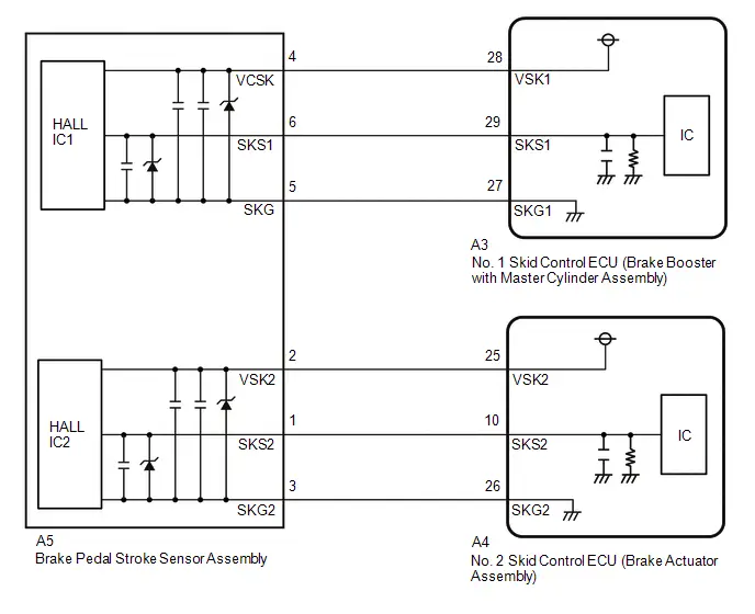
CAUTION / NOTICE / HINT
NOTICE:
Make sure to wait 5 minutes or more with the ignition switch turned off before removing the integration control supply or disconnecting any supply power circuit from the integration control supply, in order for the voltage to be discharged and self-diagnosis to run.
PROCEDURE
| 1. | CHECK HARNESS AND CONNECTOR (BRAKE BOOSTER WITH MASTER CYLINDER ASSEMBLY - BRAKE PEDAL STROKE SENSOR ASSEMBLY) |
Procedure1
(a) Make sure that there is no looseness at the locking part and the connecting part of the connectors.
OK:
The connector is securely connected.
Pre-procedure1
(b) Disconnect the A3 No. 1 skid control ECU (brake booster with master cylinder assembly) connector.
(c) Disconnect the A5 brake pedal stroke sensor assembly connector.
Procedure2
(d) Check both the connector case and the terminals for deformation and corrosion.
OK:
No deformation or corrosion.
Procedure3
(e) Measure the resistance according to the value(s) in the table below.
Standard Resistance:
 Click Location & Routing(A3,A5) Click Connector(A3) Click Connector(A5)
 | Tester Connection | Condition | Specified Condition | Result |
|---|---|---|---|
| A3-29 (SKS1) - A5-6 (SKS1) | Always | Below 1 Ω | Ω |
| A3-29 (SKS1) or A5-6 (SKS1) - Body ground | Always | 10 kΩ or higher | kΩ |
Post-procedure1
(f) None
| OK |

| REPLACE BRAKE PEDAL STROKE SENSOR ASSEMBLY
|


| NG |

| REPAIR OR REPLACE HARNESS OR CONNECTOR |
Brake Pedal Position Sensor "A" Supply Voltage Circuit Voltage Out of Range (C11001C)
DESCRIPTION
Refer to DTC C110000.
Click here

| DTC No. | Detection Item | DTC Detection Condition | Trouble Area | MIL | DTC Output from | Priority | Note |
|---|---|---|---|---|---|---|---|
| C11001C | Brake Pedal Position Sensor "A" Supply Voltage Circuit Voltage Out of Range | The sensor supply voltage (VCSK) is 4.7 V or less, or 5.3 V or more for 0.2 seconds or more. |
| Comes on | Brake Booster | A |
|
MONITOR DESCRIPTION
The No. 2 skid control ECU (brake actuator assembly) monitors the power supply voltage of the brake pedal stroke sensor assembly. When the brake pedal stroke sensor assembly power supply voltage is outside of the normal range, the No. 2 skid control ECU (brake actuator assembly) judges that the power supply is abnormal and illuminates the MIL and stores this DTC.
MONITOR STRATEGY
| Related DTCs | C1100 (Case 1): Brake pedal position sensor voltage circuit/open |
| Required Sensors/Components(Main) | No. 2 skid control ECU (brake actuator assembly) |
| Required Sensors/Components(Related) | No. 2 skid control ECU (brake actuator assembly) |
| Frequency of Operation | Continuous |
| Duration | 0.198 seconds |
| MIL Operation | Immediately |
| Sequence of Operation | None |
TYPICAL ENABLING CONDITIONS
| Monitor runs whenever the following DTCs are not stored | None |
| Both of the following conditions are met | A and B |
| A. Both of the following conditions are met | More than 0.198 seconds |
| BS cut MOS | Valid |
| BS cut MOS voltage | Higher than 7.4 V |
| B. VCSK | Valid |
| BS cut MOS voltage | Higher than 7.8 V |
TYPICAL MALFUNCTION THRESHOLDS
| Brake pedal position sensor power supply | Below 4.8 V, or higher than 5.2 V |
COMPONENT OPERATING RANGE
| Both of the following conditions are met | A and B |
| A. Both of the following conditions are met | More than 0.198 seconds |
| BS cut MOS | Valid |
| BS cut MOS voltage | Higher than 7.4 V |
| B. VCSK | Valid |
| Brake pedal position sensor1 power supply | 4.8 V or higher, and 5.2 V or less |
CONFIRMATION DRIVING PATTERN
NOTICE:
When performing the normal judgment procedure, make sure that the driver door is closed and is not opened at any time during the procedure.
HINT:
- After repair has been completed, clear the DTC and then check that the Toyota Prius vehicle has returned to normal by performing the following All Readiness check procedure.
- When clearing the permanent DTCs, refer to the "CLEAR PERMANENT DTC" procedure.
- Connect the GTS to the DLC3.
- Turn the ignition switch to ON and turn the GTS on.
- Clear the DTCs (even if no DTCs are stored, perform the clear DTC procedure).
- Turn the ignition switch off.
- Turn the ignition switch to ON (READY) and turn the GTS on.
-
Wait for 1 second or more. [*]
HINT:
[*]: Normal judgment procedure.
The normal judgment procedure is used to complete DTC judgment and also used when clearing permanent DTCs.
-
Enter the following menus: Chassis / Brake/EPB* / Utility / All Readiness.
*: Electric Parking Brake System
-
Check the DTC judgment result.
HINT:
- If the judgment result shows NORMAL, the system is normal.
- If the judgment result shows ABNORMAL, the system has a malfunction.
- If the judgment result shows INCOMPLETE, perform driving pattern again.
WIRING DIAGRAM
Refer to DTC C110000.
Click here

CAUTION / NOTICE / HINT
NOTICE:
Make sure to wait 5 minutes or more with the ignition switch turned off before removing the integration control supply or disconnecting any supply power circuit from the integration control supply, in order for the voltage to be discharged and self-diagnosis to run.
PROCEDURE
| 1. | CHECK BRAKE PEDAL |
(a) Check that the brake pedal and the brake pedal stroke sensor assembly are properly installed and that the pedal can be depressed normally.
(b) Check and adjust the brake pedal height.
HINT:
Click here

(c) Adjust the brake pedal stroke sensor assembly.
HINT:
Click here

|

| 2. | CHECK HARNESS AND CONNECTOR (BRAKE BOOSTER WITH MASTER CYLINDER ASSEMBLY - BRAKE PEDAL STROKE SENSOR ASSEMBLY) |
Pre-procedure1
(a) Turn the ignition switch off.
Procedure1
(b) Make sure that there is no looseness at the locking part and the connecting part of the connectors.
OK:
The connector is securely connected.
Pre-procedure2
(c) Disconnect the A3 No. 1 skid control ECU (brake booster with master cylinder assembly) connector.
(d) Disconnect the A5 brake pedal stroke sensor assembly connector.
Procedure2
(e) Check both the connector case and the terminals for deformation and corrosion.
OK:
No deformation or corrosion.
Procedure3
(f) Measure the resistance according to the value(s) in the table below.
Standard Resistance:
 Click Location & Routing(A3,A5) Click Connector(A3) Click Connector(A5)
 | Tester Connection | Condition | Specified Condition | Result |
|---|---|---|---|
| A3-27 (SKG1) - A5-5 (SKG) | Always | Below 1 Ω | Ω |
| A3-27 (SKG1) or A5-5 (SKG) - Body ground | Always | 10 kΩ or higher | kΩ |
| A3-28 (VSK1) - A5-4 (VCSK) | Always | Below 1 Ω | Ω |
| A3-28 (VSK1) or A5-4 (VCSK) - Body ground | Always | 10 kΩ or higher | kΩ |
Post-procedure1
(g) None
| NG |

| REPAIR OR REPLACE HARNESS OR CONNECTOR |
|

| 3. | INSPECT BRAKE BOOSTER WITH MASTER CYLINDER ASSEMBLY (SENSOR OUTPUT) |
Pre-procedure1
(a) Reconnect the A3 No. 1 skid control ECU (brake booster with master cylinder assembly) connector.
(b) Turn the ignition switch to ON.
Procedure1
(c) Measure the voltage according to the value(s) in the table below.
Standard Voltage:
 Click Location & Routing(A5) Click Connector(A5)
 | Tester Connection | Condition | Specified Condition | Result |
|---|---|---|---|
| A5-4 (VCSK) - A5-5 (SKG) | Ignition switch ON | 4.84 to 5.16 V | V |
Post-procedure1
(d) None
| OK |

| REPLACE BRAKE PEDAL STROKE SENSOR ASSEMBLY
|


| NG |

| REPLACE BRAKE BOOSTER WITH MASTER CYLINDER ASSEMBLY
|


Brake Pedal Position Sensor "B" Supply Voltage Circuit Voltage Out of Range (C11031C)
DESCRIPTION
Refer to DTC C110000.
Click here

| DTC No. | Detection Item | DTC Detection Condition | Trouble Area | MIL | DTC Output from | Priority | Note |
|---|---|---|---|---|---|---|---|
| C11031C | Brake Pedal Position Sensor "B" Supply Voltage Circuit Voltage Out of Range | The sensor supply voltage (VSK2) is 4.7 V or less, or 5.3 V or more for 0.2 seconds or more. |
| Comes on | Brake/EPB | A |
|
MONITOR DESCRIPTION
The No. 2 skid control ECU (brake actuator assembly) monitors the power supply voltage of the brake pedal stroke sensor assembly. When the brake pedal stroke sensor assembly power supply voltage is outside of the normal range, the No. 2 skid control ECU (brake actuator assembly) judges that the power supply is abnormal and illuminates the MIL and stores this DTC.
MONITOR STRATEGY
| Related DTCs | C1103 (Case 1): Brake pedal position sensor voltage circuit open |
| Required Sensors/Components(Main) | No. 2 skid control ECU (brake actuator assembly) |
| Required Sensors/Components(Related) | No. 2 skid control ECU (brake actuator assembly) |
| Frequency of Operation | Continuous |
| Duration | 0.198 seconds |
| MIL Operation | Immediately |
| Sequence of Operation | None |
TYPICAL ENABLING CONDITIONS
| Monitor runs whenever the following DTCs are not stored | None |
| All of the following conditions are met | A, B, C and D |
| A. Following condition is met | More than 0.22 seconds |
| BS voltage | 8.5 V or higher |
| B. BS voltage | 9.5 V or higher |
| C. IGR voltage | Higher than 10 V |
| D. IGP voltage | Higher than 10 V |
TYPICAL MALFUNCTION THRESHOLDS
| Brake pedal position sensor2 power supply | Below 4.8 V, or higher than 5.2 V |
COMPONENT OPERATING RANGE
| All of the following conditions are met | A and B |
| A. Following condition is met | More than 0.22 seconds |
| BS voltage | 8.5 V or higher |
| B. Brake pedal position sensor2 power supply | 4.8 V or higher, and 5.2 V or less |
CONFIRMATION DRIVING PATTERN
NOTICE:
When performing the normal judgment procedure, make sure that the driver door is closed and is not opened at any time during the procedure.
HINT:
- After repair has been completed, clear the DTC and then check that the Toyota Prius vehicle has returned to normal by performing the following All Readiness check procedure.
- When clearing the permanent DTCs, refer to the "CLEAR PERMANENT DTC" procedure.
- Connect the GTS to the DLC3.
- Turn the ignition switch to ON and turn the GTS on.
- Clear the DTCs (even if no DTCs are stored, perform the clear DTC procedure).
- Turn the ignition switch off.
- Turn the ignition switch to ON (READY) and turn the GTS on.
-
Wait for 1 second or more. [*]
HINT:
[*]: Normal judgment procedure.
The normal judgment procedure is used to complete DTC judgment and also used when clearing permanent DTCs.
-
Enter the following menus: Chassis / Brake/EPB* / Utility / All Readiness.
*: Electric Parking Brake System
-
Check the DTC judgment result.
HINT:
- If the judgment result shows NORMAL, the system is normal.
- If the judgment result shows ABNORMAL, the system has a malfunction.
- If the judgment result shows INCOMPLETE, perform driving pattern again.
WIRING DIAGRAM
Refer to DTC C110000.
Click here

PROCEDURE
| 1. | CHECK BRAKE PEDAL |
(a) Check that the brake pedal and the brake pedal stroke sensor assembly are properly installed and that the pedal can be depressed normally.
(b) Check and adjust the brake pedal height.
HINT:
Click here

(c) Adjust the brake pedal stroke sensor assembly.
HINT:
Click here

|

| 2. | CHECK HARNESS AND CONNECTOR (BRAKE ACTUATOR ASSEMBLY - BRAKE PEDAL STROKE SENSOR ASSEMBLY) |
Pre-procedure1
(a) Turn the ignition switch off.
Procedure1
(b) Make sure that there is no looseness at the locking part and the connecting part of the connectors.
OK:
The connector is securely connected.
Pre-procedure2
(c) Disconnect the A4 No. 2 skid control ECU (brake actuator assembly) connector.
(d) Disconnect the A5 brake pedal stroke sensor assembly connector.
Procedure2
(e) Check both the connector case and the terminals for deformation and corrosion.
OK:
No deformation or corrosion.
Procedure3
(f) Measure the resistance according to the value(s) in the table below.
Standard Resistance:
 Click Location & Routing(A4,A5) Click Connector(A4) Click Connector(A5)
 | Tester Connection | Condition | Specified Condition | Result |
|---|---|---|---|
| A4-26 (SKG2) - A5-3 (SKG2) | Always | Below 1 Ω | Ω |
| A4-26 (SKG2) or A5-3 (SKG2) - Body ground | Always | 10 kΩ or higher | kΩ |
| A4-25 (VSK2) - A5-2 (VSK2) | Always | Below 1 Ω | Ω |
| A4-25 (VSK2) or A5-2 (VSK2) - Body ground | Always | 10 kΩ or higher | kΩ |
Post-procedure1
(g) None
| NG |

| REPAIR OR REPLACE HARNESS OR CONNECTOR |
|

| 3. | INSPECT BRAKE ACTUATOR ASSEMBLY (SENSOR OUTPUT) |
Pre-procedure1
(a) Reconnect the A4 No. 2 skid control ECU (brake actuator assembly) connector.
(b) Turn the ignition switch to ON.
Procedure1
(c) Measure the voltage according to the value(s) in the table below.
Standard Voltage:
 Click Location & Routing(A5) Click Connector(A5)
 | Tester Connection | Condition | Specified Condition | Result |
|---|---|---|---|
| A5-2 (VSK2) - A5-3 (SKG2) | Ignition switch ON | 4.84 to 5.16 V | V |
Post-procedure1
(d) None
| OK |

| REPLACE BRAKE PEDAL STROKE SENSOR ASSEMBLY
|


| NG |

| REPLACE BRAKE ACTUATOR ASSEMBLY
|


Brake Pressure Sensor "H" / Brake Pedal Position Sensor Signal Compare Failure (C116C62)
DESCRIPTION
If the No. 1 skid control ECU (brake booster with master cylinder assembly) detects an inconsistency between the brake pedal stroke sensor assembly signal and stroke simulator pressure sensor signal, this DTC is stored.
HINT:
Brake pressure sensor "H": Stroke simulator pressure sensor
| DTC No. | Detection Item | DTC Detection Condition | Trouble Area | MIL | DTC Output from | Priority | Note |
|---|---|---|---|---|---|---|---|
| C116C62 | Brake Pressure Sensor "H" / Brake Pedal Position Sensor Signal Compare Failure | The difference between brake pedal stroke sensor assembly output value and stroke simulator pressure sensor output value is above the threshold for a certain period of time. |
| Comes on | Brake Booster | A |
|
MONITOR DESCRIPTION
The No. 2 skid control ECU (brake actuator assembly) monitors the ratio of output value of the brake pedal stroke sensor assembly and stroke simulator pressure sensor. When in linear mode (switching solenoid (SSA) on), the brake pedal is being operated and the ratio of the output value of the brake pedal stroke sensor assembly and stroke simulator pressure sensor is outside the normal range, the No. 2 skid control ECU (brake actuator assembly) judges that the ratio of the output value of the brake pedal stroke sensor assembly and stroke simulator pressure sensor is abnormal and illuminates the MIL and stores this DTC.
MONITOR STRATEGY
| Related DTCs | C116C: Brake position/ stroke simulator pressure correlation |
| Required Sensors/Components(Main) | Brake actuator (brake booster with master cylinder assembly) Brake pedal stroke sensor assembly |
| Required Sensors/Components(Related) | No. 2 skid control ECU (brake actuator assembly) Brake actuator (brake booster with master cylinder assembly) Brake pedal stroke sensor assembly Stop light switch assembly |
| Frequency of Operation | Continuous |
| Duration | 1.008 seconds |
| MIL Operation | Immediately |
| Sequence of Operation | None |
TYPICAL ENABLING CONDITIONS
| Monitor runs whenever the following DTCs are not stored | C05A1 (Case 1): Servo pressure sensor lost communication C05A1 (Case 2): Servo pressure sensor internal malfunction C05A1 (Case 3): Servo pressure sensor invalid data C05A2: Servo pressure sensor exceeded learning limit C05C0: Brake pedal position sensor learning not complete C05C1: Brake pedal position sensor learning not complete C0639 (Case 1): Stroke simulator pressure sensor Lost communication C0639 (Case 2): Stroke simulator pressure sensor internal check C0639 (Case 3): Stroke simulator pressure sensor invalid data C1100 (Case 1): Brake pedal position sensor voltage circuit/open C1100 (Case 2): Brake pedal position sensor invalid data C1103 (Case 1): Brake pedal position sensor voltage circuit/open C1103 (Case 2): Brake pedal position sensor invalid data C1168: Stroke simulator pressure sensor intermittent/erratic C116A: Stroke simulator pressure sensor voltage circuit low C116B: Stroke simulator pressure sensor voltage circuit high C116D: Brake pressure control solenoid (SLM1) stuck on C121F: Brake system voltage performance C129B: Rotation angle sensor range/performance C12B4 (Case 1): Brake booster motor not rotate C12B4 (Case 2): Brake booster motor performance (motor current) C12BF (Case 1 to 4): Brake booster motor performance (motor upper circuit) C12BF (Case 5 to 9): Brake booster motor performance (motor drive circuit) C12FA: Brake system voltage power supply relay open circuit C12FB: Brake system voltage power supply relay circuit high C1345: Brake pressure control solenoid open current learning not complete C13BB: Brake booster motor range/performance C13D9: Brake pressure too low C1498: Servo pressure sensor voltage circuit low C1499: Servo pressure sensor voltage circuit high C14C4: Servo pressure sensor intermittent/erratic C14CE: High pressure hydraulic tube air bleeding not complete C14F3 (Case 1 to 3) Brake pressure control solenoid (SLM1) circuit open C14F3 (Case 4 to 5) Brake pressure control solenoid (SLM1) circuit low C14F4 (Case 1 to 2): Brake pressure control solenoid (SLM2) circuit high (solenoid OFF current) C14F4 (Case 3 to 6): Brake pressure control solenoid (SLM2) circuit high (IC data) C14F4 (Case 7 to 8): Brake pressure control solenoid (SLM2) circuit high (solenoid ON current) C14FD (Case 1 to 2): Brake pressure control solenoid (SLM1) circuit high (solenoid OFF current) C14FD (Case 3 to 6): Brake pressure control solenoid (SLM1) circuit high (IC data) C14FD (Case 7 to 8): Brake pressure control solenoid (SLM1) circuit high (solenoid ON current) C1509: Brake pressure control solenoid (SSA) circuit low C150A: Brake pressure control solenoid (SSA) circuit high C150F: Brake pressure control solenoid (SGH) circuit low C1510: Brake pressure control solenoid (SGH) circuit high P057A: Brake pedal position sensor invalid data P057C: Brake pedal position sensor open circuit P057D: Brake pedal position sensor circuit high P057E: Brake pedal position sensor intermittent/erratic P05DB: Brake pedal position sensor invalid data P05DD: Brake pedal position sensor open circuit P05DE: Brake pedal position sensor circuit high P05DF: Brake pedal position sensor intermittent/erratic P05E0: Brake pedal position sensor "A"/"B" correlation U0129: Lost communication with BSCM (CH1) U025E: Lost communication with BSCM2 (CH1) |
| All of the following conditions are met | - |
| Brake pedal position sensor fail | Not detected |
| Stroke simulator pressure sensor fail | Not detected |
| Brake-by-wire controlled mode | On |
| Brake pedal operation | On |
| Last brake off duration time | 3 seconds or more |
| Maximum Psrv during braking | Below 0.1 MPa (1 kgf/cm2, 15 psi) |
TYPICAL MALFUNCTION THRESHOLDS
| Following condition is met | 3 times or more |
| Ratio of the output value of the brake pedal stroke sensor assembly and stroke simulator pressure sensor | Within the invalid area (a) or invalid area (b) of the following Map A or Map B |
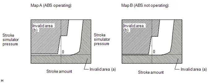
COMPONENT OPERATING RANGE
| All of the following conditions are met | - |
| Brake position sensor circuit fail | Not detected |
| Stroke simulator pressure sensor circuit fail | Not detected |
| Brake-by-wire controlled mode | On |
| Brake pedal operation | On |
| BSCM2 fail (C121F) | Not detected |
| Brake system voltage fail (C12FA, C12FB) | Not detected |
| Brake pedal position sensor fail (C05C0, C05C1, C1100, C1103, P057A, P057C, P057D, P057E, P05DB, P05DD, P05DE, P05DF, P05E0) | Not detected |
| Pressure sensor fail (C05A1, C05A2, C1498, C1499, C14C4, C116A, C116B, C0639, C063C, C1168) | Not detected |
| CAN communication fail (U0129, U025E) | Not detected |
| Brake pressure control solenoid fail (C1345, C14F4, C14FD, C150A, C1510, C14F3, C14FC, C1509, C150F, C116D, C13D9, C14CE) | Not detected |
| Brake booster motor fail (C12BF, C13BB, C12B4) | Not detected |
| Rotation angle sensor fail (C129B) | Not detected |
| Ratio of the output value of the brake pedal stroke sensor assembly and stroke simulator pressure sensor | Within the valid area of the Map C |
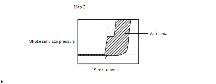
CONFIRMATION DRIVING PATTERN
NOTICE:
When performing the normal judgment procedure, make sure that the driver door is closed and is not opened at any time during the procedure.
HINT:
- After repair has been completed, clear the DTC and then check that the Toyota Prius vehicle has returned to normal by performing the following All Readiness check procedure.
- When clearing the permanent DTCs, refer to the "CLEAR PERMANENT DTC" procedure.
- Connect the GTS to the DLC3.
- Turn the ignition switch to ON and turn the GTS on.
- Clear the DTCs (even if no DTCs are stored, perform the clear DTC procedure).
- Turn the ignition switch off.
- Turn the ignition switch to ON (READY) and turn the GTS on.
-
Depress the brake pedal 3 or more times. [*]
HINT:
[*]: Normal judgment procedure.
The normal judgment procedure is used to complete DTC judgment and also used when clearing permanent DTCs.
-
Enter the following menus: Chassis / Brake/EPB* / Utility / All Readiness.
*: Electric Parking Brake System
-
Check the DTC judgment result.
HINT:
- If the judgment result shows NORMAL, the system is normal.
- If the judgment result shows ABNORMAL, the system has a malfunction.
- If the judgment result shows INCOMPLETE, perform driving pattern again.
CAUTION / NOTICE / HINT
NOTICE:
If the detection conditions for X2442 are met 3 times in a row in the same trip, DTC C116C62 is stored.
PROCEDURE
| 1. | CUSTOMER PROBLEM ANALYSIS (CHECK CONDITION WHEN MALFUNCTION OCCURRED) AND FREEZE FRAME DATA |
Pre-procedure1
(a) Interview the customer to check the Toyota Prius vehicle conditions when the brake system warning light (red indicator) and brake system warning light (yellow indicator) illuminated.
Procedure1
(b) Using the GTS, check for Freeze Frame Data that is recorded when a DTC is stored.
HINT:
Click here

HINT:
- Freeze Frame Data is only stored once when a DTC is stored.
- If other DTCs are output, repair any malfunctions related to those DTCs first, and then reproduce the conditions that caused DTC C116C62 to be stored based on the interview with the customer.
Post-procedure1
(c) None
|

| 2. | READ VALUE USING GTS (STROKE SENSOR) |
(a) With the brake pedal released, confirm the brake pedal stroke sensor assembly output voltage.
Chassis > Brake Booster > Data List| Tester Display | Measurement Item | Range | Normal Condition | Diagnostic Note |
|---|---|---|---|---|
| Stroke Sensor | Brake pedal stroke sensor 1 | Min.: 0.0 V Max.: 5.0 V | Brake pedal released: 0.6 to 1.4 V | Reading increases when brake pedal is depressed |
| Tester Display |
|---|
| Stroke Sensor |
| Result | Proceed to |
|---|---|
| The value of Stroke Sensor is between 0.6 and 1.4 V | A |
| None of the above conditions are met | B |
| B |

| INSPECT/ADJUST INSTALLATION CONDITION OF BRAKE PEDAL STROKE SENSOR ASSEMBLY |
|

| 3. | READ VALUE USING GTS (STROKE SENSOR) |
Pre-procedure1
(a) Turn the ignition switch off.
(b) Mount a pedal effort gauge.
(c) Turn the ignition switch to ON (READY) and depress the brake pedal once.
HINT:
Depress the brake pedal after turning the ignition switch to ON (READY) to set the Toyota Prius vehicle to linear mode (switching solenoid (SSA) on).
Procedure1
(d) Depress the brake pedal slowly and check the brake pedal stroke sensor assembly output voltages with respect to brake pedal depression force.
Chassis > Brake Booster > Data List| Tester Display | Measurement Item | Range | Normal Condition | Diagnostic Note |
|---|---|---|---|---|
| Stroke Sensor | Brake pedal stroke sensor 1 | Min.: 0.0 V Max.: 5.0 V | Brake pedal released: 0.6 to 1.4 V | Reading increases when brake pedal is depressed |
| Tester Display |
|---|
| Stroke Sensor |
HINT:
Perform this procedure in linear mode (switching solenoid (SSA) on).
Standard Voltage:
| Pedal Effort [N (kgf, lbf)] | Stroke Sensor [V] |
|---|---|
| 50 (5, 11.2) | 0.96 to 1.67 |
| 100 (10, 22.5) | 1.14 to 1.86 |
| 150 (15, 33.7) | 1.23 to 1.95 |
Post-procedure1
(e) None
| NG |

| REPLACE BRAKE PEDAL STROKE SENSOR ASSEMBLY
|


|

| 4. | READ VALUE USING GTS (GAP HOLD CHAMBER OIL PRESSURE) |
(a) Depress the brake pedal slowly and check the gap pressure sensor output values with respect to brake pedal depression force.
Chassis > Brake Booster > Data List| Tester Display | Measurement Item | Range | Normal Condition | Diagnostic Note |
|---|---|---|---|---|
| Gap Hold Chamber Oil Pressure | Pressure value of stroke simulator | Min.: 0.00 MPa Max.: 24.48 MPa | Brake pedal released: 0.00 to 1.53 MPa | Brake pedal is being depressed: Changes in proportion to the depression force of the brake pedal |
| Tester Display |
|---|
| Gap Hold Chamber Oil Pressure |
HINT:
Perform this procedure in linear mode (switching solenoid (SSA) on).
Standard Pressure:
| Pedal Effort [N (kgf, lbf)] | Gap Hold Chamber Oil Pressure [MPa] |
|---|---|
| 50 (5, 11.2) | 0.00 to 0.75 |
| 100 (10, 22.5) | 0.63 to 1.43 |
| 150 (15, 33.7) | 1.33 to 2.13 |
| 200 (20, 45.0) | 2.03 to 2.83 |
| NG |

| CHECK AND REPAIR BRAKE FLUID LEAKS |
|

| 5. | CLEAR DTC |
Pre-procedure1
(a) None
Procedure1
(b) Clear the DTCs.
Chassis > Brake Booster > Clear DTCsPost-procedure1
(c) Turn the ignition switch off.
|

| 6. | RECONFIRM DTC |
Pre-procedure1
(a) Based on the Freeze Frame Data and interview with the customer, attempt to reproduce the conditions when the malfunction occurred.
Procedure1
(b) Check if the same DTC is output.
Chassis > Brake Booster > Trouble Codes| Result | Proceed to |
|---|---|
| C116C62 is not output | A |
| C116C62 is output | B |
Post-procedure1
(c) None
| A |

| END |
| B |

| REPLACE BRAKE BOOSTER WITH MASTER CYLINDER ASSEMBLY
|


Brake Servo Pressure Sensor Pressure Increase Malfunction (C116D00)
DESCRIPTION
In order for the No. 1 skid control ECU (brake booster with master cylinder assembly) to control braking force in coordination with the regenerative braking by the hybrid control system, the operating fluid pressures of the master cylinder and each wheel cylinder are input via the servo pressure sensor.
DTCs may be stored if one of the following occurs:
- Brake fluid leaks.
- Foreign matter enters a solenoid valve.
- Line pressure drops during air bleeding.
- Brake pads are replaced.
- Rotors are replaced.
| DTC No. | Detection Item | DTC Detection Condition | Trouble Area | MIL | DTC Output from | Priority | Note |
|---|---|---|---|---|---|---|---|
| C116D00 | Brake Servo Pressure Sensor Pressure Increase Malfunction | The brake servo pressure decreases significantly (Poor boost malfunction) |
| Comes on | Brake Booster | A |
|
MONITOR DESCRIPTION
When the brake pedal is depressed, the No. 1 skid control ECU (brake booster with master cylinder assembly) monitors the servo pressure and increases the servo pressure by driving the linear solenoid (SLM1).When the brake pedal is depressed, if the actual servo pressure does not change even when the target servo pressure increases for a certain amount of time, the No. 2 skid control ECU (brake actuator assembly) judges that the linear solenoid (SLM1) is stuck closed (the pressure increase during initial braking is abnormal) and illuminates the MIL and stores this DTC.
MONITOR STRATEGY
| Related DTCs | C116D: Brake pressure control solenoid (SLM1) stuck on |
| Required Sensors/Components(Main) | No. 2 skid control ECU (brake actuator assembly) Brake actuator (brake booster with master cylinder assembly) |
| Required Sensors/Components(Related) | Stop light switch assembly No. 2 skid control ECU (brake actuator assembly) Brake actuator (brake booster with master cylinder assembly) |
| Frequency of Operation | Continuous |
| Duration | 0.072 seconds |
| MIL Operation | Immediately |
| Sequence of Operation | None |
TYPICAL ENABLING CONDITIONS
| Monitor runs whenever the following DTCs are not stored | C05A1 (Case 1): Servo pressure sensor lost communication C05A1 (Case 2): Servo pressure sensor internal malfunction C05A1 (Case 3): Servo pressure sensor invalid data C05A2: Servo pressure sensor exceeded learning limit C05C0: Brake pedal position sensor learning not complete C05C1: Brake pedal position sensor learning not complete C0639 (Case 1): Stroke simulator pressure sensor Lost communication C0639 (Case 2): Stroke simulator pressure sensor internal check C0639 (Case 3): Stroke simulator pressure sensor invalid data C063C: Stroke simulator pressure sensor exceeded learning limit C1100 (Case 1): Brake pedal position sensor voltage circuit/open C1100 (Case 2): Brake pedal position sensor invalid data C1103 (Case 1): Brake pedal position sensor voltage circuit/open C1103 (Case 2): Brake pedal position sensor invalid data C1168: Stroke simulator pressure sensor intermittent/erratic C116A: Stroke simulator pressure sensor voltage circuit low C116B: Stroke simulator pressure sensor voltage circuit high C116C: Brake position / stroke simulator pressure correlation C121F: Brake system voltage performance C129B: Rotation angle sensor range/performance C12B4 (Case 1): Brake booster motor not rotate C12B4 (Case 2): Brake booster motor performance (motor current) C12BF (Case 1 to 4): Brake booster motor performance (motor upper circuit) C12BF (Case 5 to 9): Brake booster motor performance (motor drive circuit) C12FA: Brake system voltage power supply relay open circuit C12FB: Brake system voltage power supply relay circuit high C1345: Brake pressure control solenoid open current learning not complete C13BB: Brake booster motor range/performance C13D9: Brake pressure too low C1498: Servo pressure sensor voltage circuit low C1499: Servo pressure sensor voltage circuit high C14C4: Servo pressure sensor intermittent/erratic C14CE: High pressure hydraulic tube air bleeding not complete C14F3 (Case 1 to 3) Brake pressure control solenoid (SLM1) circuit open C14F3 (Case 4 to 5) Brake pressure control solenoid (SLM1) circuit low C14F4 (Case 1 to 2): Brake pressure control solenoid (SLM2) circuit high (solenoid OFF current) C14F4 (Case 3 to 6): Brake pressure control solenoid (SLM2) circuit high (IC data) C14F4 (Case 7 to 8): Brake pressure control solenoid (SLM2) circuit high (solenoid ON current) C14FC (Case 1 to 3) Brake pressure control solenoid (SLM2) circuit open C14FC (Case 4 to 5) Brake pressure control solenoid (SLM2) circuit low C14FD (Case 1 to 2): Brake pressure control solenoid (SLM1) circuit high (solenoid OFF current) C14FD (Case 3 to 6): Brake pressure control solenoid (SLM1) circuit high (IC data) C14FD (Case 7 to 8): Brake pressure control solenoid (SLM1) circuit high (solenoid ON current) C1509: Brake pressure control solenoid (SSA) circuit low C150A: Brake pressure control solenoid (SSA) circuit high C150F: Brake pressure control solenoid (SGH) circuit low C1510: Brake pressure control solenoid (SGH) circuit high P057A: Brake pedal position sensor invalid data P057C: Brake pedal position sensor open circuit P057D: Brake pedal position sensor circuit high P057E: Brake pedal position sensor intermittent/erratic P05DB: Brake pedal position sensor invalid data P05DD: Brake pedal position sensor open circuit P05DE: Brake pedal position sensor circuit high P05DF: Brake pedal position sensor intermittent/erratic P05E0: Brake pedal position sensor "A"/"B" correlation U0129: Lost communication with BSCM (CH1) U025E: Lost communication with BSCM2 (CH1) |
| All of the following conditions are met | A, B, C and D |
| A. Servo pressure sensor fail | Not detected |
| B. Brake-by-wire controlled mode | On |
| C. Either of the following conditions is met | a or b |
| a. Target servo pressure | 0.5 MPa (5.1 kgf/cm2, 73 psi) or higher |
| ABS/TRAC/VSC operation | Off |
| b. Target servo pressure | 3.0 MPa (30.6 kgf/cm2, 435 psi) or higher |
| ABS/TRAC/VSC operation | On |
| D. Brake | On |
TYPICAL MALFUNCTION THRESHOLDS
| Servo pressure | 0.1 MPa (1 kgf/cm2, 15 psi) or less |
COMPONENT OPERATING RANGE
| All of the following conditions are met | - |
| Servo pressure sensor fail | Not detected |
| Brake-by-wire controlled mode | On |
| Brake | On |
| BSCM2 fail (C121F) | Not detected |
| Brake system voltage fail (C12FA, C12FB) | Not detected |
| Brake pedal position sensor fail (C05C0, C05C1, C1100, C1103, P057A, P057C, P057D, P057E, P05DB, P05DD, P05DE, P05DF, P05E0) | Not detected |
| Pressure sensor fail sensor fail (C05A1, C05A2, C1498, C1499, C14C4, C116A, C116B, C0639, C063C, C1168, C116C) | Not detected |
| CAN communication fail (U0129, U025E) | Not detected |
| Brake pressure control solenoid fail(C1345, C14F4, C14FD, C150A, C1510, C14F3, C14FC, C1509, C150F, C13D9, C14CE) | Not detected |
| Brake booster motor fail (C12BF, C13BB, C12B4) | Not detected |
| Rotation angle sensor fail (C129B) | Not detected |
| Servo pressure | Higher than 0.1 MPa (1 kgf/cm2, 15 psi) |
CONFIRMATION DRIVING PATTERN
NOTICE:
When performing the normal judgment procedure, make sure that the driver door is closed and is not opened at any time during the procedure.
HINT:
- After repair has been completed, clear the DTC and then check that the Toyota Prius vehicle has returned to normal by performing the following All Readiness check procedure.
- When clearing the permanent DTCs, refer to the "CLEAR PERMANENT DTC" procedure.
- Connect the GTS to the DLC3.
- Turn the ignition switch to ON and turn the GTS on.
- Clear the DTCs (even if no DTCs are stored, perform the clear DTC procedure).
- Drive the Toyota Prius vehicle at 3 km/h (2 mph) or more for 1 second.
- Turn the ignition switch off.
- Wait 4 minutes.
- Turn the ignition switch to ON (READY) and turn the GTS on.
-
Depress the brake pedal for 2 seconds, release it and wait 1 second. [*]
HINT:
[*]: Normal judgment procedure.
The normal judgment procedure is used to complete DTC judgment and also used when clearing permanent DTCs.
-
Enter the following menus: Chassis / Brake/EPB* / Utility / All Readiness.
*: Electric Parking Brake System
-
Check the DTC judgment result.
HINT:
- If the judgment result shows NORMAL, the system is normal.
- If the judgment result shows ABNORMAL, the system has a malfunction.
- If the judgment result shows INCOMPLETE, perform driving pattern again.
CAUTION / NOTICE / HINT
NOTICE:
Make sure to wait 5 minutes or more with the ignition switch turned off before removing the integration control supply or disconnecting any supply power circuit from the integration control supply, in order for the voltage to be discharged and self-diagnosis to run.
PROCEDURE
| 1. | CUSTOMER PROBLEM ANALYSIS (CHECK CONDITION WHEN MALFUNCTION OCCURRED) AND FREEZE FRAME DATA |
Pre-procedure1
(a) Interview the customer to check the Toyota Prius vehicle conditions when the brake system warning light (yellow indicator) illuminated.
Procedure1
(b) Using the GTS, check for Freeze Frame Data that is recorded when a DTC is stored.
HINT:
Click here

HINT:
Freeze Frame Data is only stored once when a DTC is stored.
Post-procedure1
(c) None
|

| 2. | CLEAR DTC |
Pre-procedure1
(a) None
Procedure1
(b) Clear the DTCs.
Chassis > Brake Booster > Clear DTCs Chassis > Brake/EPB > Clear DTCsPost-procedure1
(c) Turn the ignition switch off.
|

| 3. | CHECK DTC |
Pre-procedure1
(a) Based on the Freeze Frame Data and interview with the customer, attempt to reproduce the conditions when the malfunction occurred.
Procedure1
(b) Check if the same DTC is output.
Chassis > Brake Booster > Trouble Codes| Result | Proceed to |
|---|---|
| Only C116D00 is output | A |
| C116D00 and other DTCs are output | B |
Post-procedure1
(c) None
| B |

| REPAIR CIRCUITS INDICATED BY OUTPUT DTCS |
|

| 4. | CHECK DTC |
(a) Check the DTCs that are output.
Chassis > Brake/EPB > Trouble Codes| Result | Proceed to |
|---|---|
| DTCs are not output | A |
| DTCs are output | B |
| B |

| REPAIR CIRCUITS INDICATED BY OUTPUT DTCS |
|

| 5. | CHECK FOR FLUID LEAK |
(a) Based on the Freeze Frame Data or interview with the customer, inspect the following items for brake fluid leaks:
- The brake lines from the brake booster with master cylinder assembly to each wheel cylinder.
- The main body of the brake booster with master cylinder assembly and brake actuator assembly.
OK:
There are no fluid leaks.
| NG |

| REPAIR OR REPLACE APPLICABLE PART |
|

| 6. | CLEAR DTC |
Pre-procedure1
(a) None
Procedure1
(b) Clear the DTCs.
Chassis > Brake Booster > Clear DTCs Chassis > Brake/EPB > Clear DTCsPost-procedure1
(c) Turn the ignition switch off.
|

| 7. | PERFORM AIR BLEEDING |
(a) Perform the air bleeding procedure in Bleed Brake System.
HINT:
Click here

|

| 8. | CHECK BRAKE BOOSTER WITH MASTER CYLINDER ASSEMBLY (ACTUATOR SIDE) |
Pre-procedure1
(a) Turn the ignition switch off.
Procedure1
(b) Make sure that there is no looseness at the locking part and the connecting part of the connectors.
OK:
The connector is securely connected.
Pre-procedure2
(c) Disconnect the A3 No. 1 skid control ECU (brake booster with master cylinder assembly) connector.
Procedure2
(d) Check both the connector case and the terminals for deformation and corrosion.
OK:
No deformation or corrosion.
Post-procedure1
(e) None
| NG |

| REPLACE BRAKE BOOSTER WITH MASTER CYLINDER ASSEMBLY
|


|

| 9. | CHECK HARNESS AND CONNECTOR (Toyota Prius Vehicle SIDE) |
Pre-procedure1
(a) Reconnect the A3 No. 1 skid control ECU (brake booster with master cylinder assembly) connector.
Procedure1
(b) Measure the voltage and resistance on the wire harness side.
HINT:
Click here

OK:
Voltage and resistance readings are all normal.
Post-procedure1
(c) None
| NG |

| REPAIR OR REPLACE HARNESS OR CONNECTOR |
|

| 10. | CLEAR DTC |
Pre-procedure1
(a) None
Procedure1
(b) Clear the DTCs.
Chassis > Brake Booster > Clear DTCs Chassis > Brake/EPB > Clear DTCsPost-procedure1
(c) Turn the ignition switch off.
|

| 11. | RECONFIRM DTC |
Pre-procedure1
(a) Based on the Freeze Frame Data and interview with the customer, attempt to reproduce the conditions when the malfunction occurred.
Procedure1
(b) Check if the same DTC is output.
Chassis > Brake Booster > Trouble CodesHINT:
If the system returns to normal, it is suspected that a DTC was stored due to a poor connection of a terminal in a connector, air in the system, etc.
| Result | Proceed to |
|---|---|
| C116D00 is not output | A |
| C116D00 is output | B |
| Only C116D00 is output | C |
Post-procedure1
(c) None
| A |

| USE SIMULATION METHOD TO CHECK |
| B |

| REPLACE BRAKE BOOSTER WITH MASTER CYLINDER ASSEMBLY
|


|

| 12. | RECONFIRM DTC |
(a) Check the DTCs that are output.
Chassis > Brake/EPB > Trouble Codes| Result | Proceed to |
|---|---|
| C140A00 is output | A |
| DTCs are not output | B |
| A |

| REPLACE BRAKE BOOSTER WITH MASTER CYLINDER ASSEMBLY AND BRAKE ACTUATOR ASSEMBLY for Brake Booster with Master Cylinder Assembly: Click here
for Brake Actuator Assembly: Click here
|


| B |

| REPLACE BRAKE BOOSTER WITH MASTER CYLINDER ASSEMBLY
|


Electronic Brake Booster Motor Supply Voltage Circuit Short to Ground or Open (C117514)
DESCRIPTION
If a malfunction is detected in the power supply circuit, the No. 1 skid control ECU (brake booster with master cylinder assembly) power source voltage drops, the No. 1 skid control ECU (brake booster with master cylinder assembly) will store these DTCs.
If the auxiliary battery voltage is temporarily low, this DTC may be stored.
| DTC No. | Detection Item | DTC Detection Condition | Trouble Area | MIL | DTC Output from | Priority | Note |
|---|---|---|---|---|---|---|---|
| C117514 | Electronic Brake Booster Motor Supply Voltage Circuit Short to Ground or Open | The BM terminal voltage monitor value is open circuit condition for 1 second or more. |
| Does not come on | Brake Booster | A | Output ECU: No. 1 skid control ECU (brake booster with master cylinder assembly) |
WIRING DIAGRAM

CAUTION / NOTICE / HINT
NOTICE:
- Inspect the fuses for circuits related to this system before performing the following procedure.
-
Before performing troubleshooting, make sure to confirm that the auxiliary battery voltage is normal.
Click here

- Make sure to wait 5 minutes or more with the ignition switch turned off before removing the integration control supply or disconnecting any supply power circuit from the integration control supply, in order for the voltage to be discharged and self-diagnosis to run.
PROCEDURE
| 1. | CHECK DTC |
(a) Check the DTCs that are output.
Chassis > Brake Booster > Trouble Codes| Result | Proceed to |
|---|---|
| Only C117514 is output | A |
| C117514 and other DTCs are output | B |
| B |

| REPAIR CIRCUITS INDICATED BY OUTPUT DTCS |
|

| 2. | CHECK DTC |
(a) Check the DTCs that are output.
Chassis > Brake/EPB > Trouble Codes| Result | Proceed to |
|---|---|
| DTCs are not output | A |
| DTCs are output | B |
| B |

| REPAIR CIRCUITS INDICATED BY OUTPUT DTCS |
|

| 3. | CHECK HARNESS AND CONNECTOR (BM TERMINAL) |
Pre-procedure1
(a) Turn the ignition switch off.
Procedure1
(b) Make sure that there is no looseness at the locking part and the connecting part of the connector.
OK:
The connector is securely connected.
Pre-procedure2
(c) Disconnect the A3 No. 1 skid control ECU (brake booster with master cylinder assembly) connector.
Procedure2
(d) Check both the connector case and the terminals for deformation and corrosion.
OK:
No deformation or corrosion.
Procedure3
(e) Measure the voltage according to the value(s) in the table below.
Standard Voltage:
 Click Location & Routing(A3) Click Connector(A3)
 | Tester Connection | Condition | Specified Condition | Result |
|---|---|---|---|
| A3-1 (BM) - Body ground | Always | 11 to 14 V | V |
Post-procedure1
(f) None
| OK |

| REPLACE BRAKE BOOSTER WITH MASTER CYLINDER ASSEMBLY
|


| NG |

| REPAIR OR REPLACE HARNESS OR CONNECTOR |
Master Reservoir Level Malfunction (C120200)
DESCRIPTION
If the No. 1 skid control ECU (brake booster with master cylinder assembly) detects that the brake fluid level is low or there is an open in the brake fluid level warning switch signal circuit, DTC C120200 is stored.
| DTC No. | Detection Item | DTC Detection Condition | Trouble Area | MIL | DTC Output from | Priority | Note |
|---|---|---|---|---|---|---|---|
| C120200 | Master Reservoir Level Malfunction | Either of the following is detected:
|
| Comes on | Brake Booster | B |
HINT: DTC C120200 is cleared when the conditions return to normal. |
MONITOR DESCRIPTION
When the ignition switch is turned to ON and the fluid level warning switch is on for a certain amount of time, the No. 2 skid control ECU (brake actuator assembly) judges that the brake fluid level in the reservoir is low and illuminates the MIL and stores this DTC.
MONITOR STRATEGY
| Related DTCs | C1202: Reservoir level too low |
| Required Sensors/Components(Main) | Brake fluid level warning switch No. 2 skid control ECU (brake actuator assembly) |
| Required Sensors/Components(Related) | No. 2 skid control ECU (brake actuator assembly) |
| Frequency of Operation | Continuous |
| Duration | 20 seconds |
| MIL Operation | Immediately |
| Sequence of Operation | None |
TYPICAL ENABLING CONDITIONS
| Monitor runs whenever the following DTCs are not stored | C120F: Reservoir level switch open circuit U0129: Lost communication with BSCM (CH1) U025E: Lost communication with BSCM2 (CH1) |
| Both of the following conditions are met | - |
| Ignition switch | On |
TYPICAL MALFUNCTION THRESHOLDS
| Reservoir level switch state | On |
COMPONENT OPERATING RANGE
| All of the following conditions are met | - |
| Ignition switch | On |
| CAN communication fail (U0129, U025E) | Not detected |
| Reservoir level switch fail (C120F) | Not detected |
| Reservoir level switch state | Off |
CONFIRMATION DRIVING PATTERN
NOTICE:
When performing the normal judgment procedure, make sure that the driver door is closed and is not opened at any time during the procedure.
HINT:
- After repair has been completed, clear the DTC and then check that the Toyota Prius vehicle has returned to normal by performing the following All Readiness check procedure.
- When clearing the permanent DTCs, refer to the "CLEAR PERMANENT DTC" procedure.
- Connect the GTS to the DLC3.
- Turn the ignition switch to ON and turn the GTS on.
- Clear the DTCs (even if no DTCs are stored, perform the clear DTC procedure).
- Turn the ignition switch off.
- Turn the ignition switch to ON (READY) and turn the GTS on.
-
Wait 20 seconds. [*]
HINT:
[*]: Normal judgment procedure.
The normal judgment procedure is used to complete DTC judgment and also used when clearing permanent DTCs.
-
Enter the following menus: Chassis / Brake/EPB* / Utility / All Readiness.
*: Electric Parking Brake System
-
Check the DTC judgment result.
HINT:
- If the judgment result shows NORMAL, the system is normal.
- If the judgment result shows ABNORMAL, the system has a malfunction.
- If the judgment result shows INCOMPLETE, perform driving pattern again.
WIRING DIAGRAM
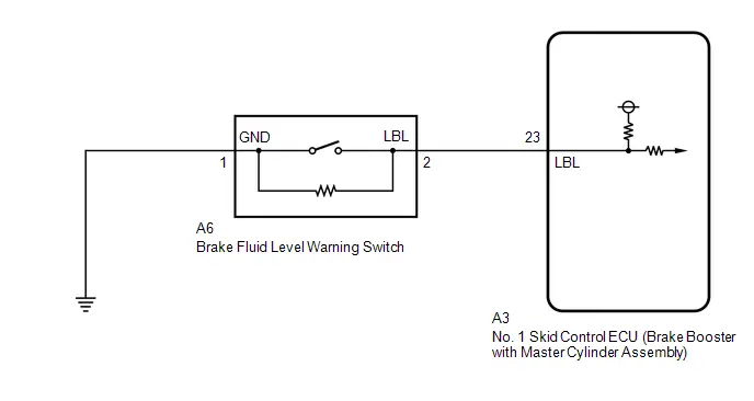
CAUTION / NOTICE / HINT
NOTICE:
Make sure to wait 5 minutes or more with the ignition switch turned off before removing the integration control supply or disconnecting any supply power circuit from the integration control supply, in order for the voltage to be discharged and self-diagnosis to run.
PROCEDURE
| 1. | CHECK DTC |
(a) Check the DTCs that are output.
Chassis > Brake Booster > Trouble Codes| Result | Proceed to |
|---|---|
| Only C120200 is output | A |
| C120200 and other DTCs are output | B |
| B |

| REPAIR CIRCUITS INDICATED BY OUTPUT DTCS |
|

| 2. | CHECK DTC |
(a) Check the DTCs that are output.
Chassis > Brake/EPB > Trouble Codes| Result | Proceed to |
|---|---|
| DTCs are not output | A |
| DTCs are output | B |
| B |

| REPAIR CIRCUITS INDICATED BY OUTPUT DTCS |
|

| 3. | CHECK BRAKE FLUID LEVEL |
(a) Check that the brake fluid level is sufficient.
HINT:
If the fluid level is low, check for fluid leaks, and repair as necessary.
(1) Check for brake fluid leaks (connection between the brake master cylinder reservoir assembly, brake booster with master cylinder assembly, brake actuator assembly and wheel cylinders).
HINT:
If no leaks exist, add and adjust fluid using the GTS.
Click here

(2) Check the thickness of the brake pad lining.
for Front Brake: Click here


for Rear Brake: Click here

HINT:
If the thickness is less than the standard, replace the brake pads with new ones.
| NG |

| CHECK AND REPAIR BRAKE FLUID LEAKS OR ADD FLUID |
|

| 4. | INSPECT BRAKE FLUID LEVEL WARNING SWITCH |
Pre-procedure1
(a) Turn the ignition switch off.
Procedure1
(b) Inspect the brake fluid level warning switch.
Click here

OK:
The brake fluid level warning switch is normal.
Post-procedure1
(c) None
| NG |

| REPLACE BRAKE BOOSTER WITH MASTER CYLINDER ASSEMBLY
|


|

| 5. | CHECK HARNESS AND CONNECTOR (BRAKE BOOSTER WITH MASTER CYLINDER ASSEMBLY - BRAKE FLUID LEVEL WARNING SWITCH) |
Pre-procedure1
(a) Turn the ignition switch off.
Procedure1
(b) Make sure that there is no looseness at the locking part and the connecting part of the connector.
OK:
The connector is securely connected.
Pre-procedure2
(c) Disconnect the A3 No. 1 skid control ECU (brake booster with master cylinder assembly) connector.
Procedure2
(d) Check both the connector case and the terminals for deformation and corrosion.
OK:
No deformation or corrosion.
Procedure3
(e) Measure the resistance according to the value(s) in the table below.
Standard Resistance:
 Click Location & Routing(A3,A6) Click Connector(A3) Click Connector(A6)
 | Tester Connection | Condition | Specified Condition | Result |
|---|---|---|---|
| A3-23 (LBL) - A6-2 (LBL) | Always | Below 1 Ω | Ω |
| A3-23 (LBL) or A6-2 (LBL)- Body ground | Always | 10 kΩ or higher | kΩ |
| A6-1 (GND) - Body ground | 1 minute or more after disconnecting the cable from the negative (-) auxiliary battery terminal | Below 1 Ω | Ω |
Post-procedure1
(f) None
| NG |

| REPAIR OR REPLACE HARNESS OR CONNECTOR |
|

| 6. | INSPECT BRAKE BOOSTER WITH MASTER CYLINDER ASSEMBLY (SWITCH INPUT) |
Pre-procedure1
(a) Reconnect the A3 No. 1 skid control ECU (brake booster with master cylinder assembly) connector.
(b) Turn the ignition switch to ON.
Procedure1
(c) Measure the voltage according to the value(s) in the table below.
Standard Voltage:
 Click Location & Routing(A6) Click Connector(A6)
 | Tester Connection | Condition | Specified Condition | Result |
|---|---|---|---|
| A6-2 (LBL) - Body ground | Ignition switch ON | 11 to 14 V | V |
Post-procedure1
(d) None
| NG |

| REPLACE BRAKE BOOSTER WITH MASTER CYLINDER ASSEMBLY
|


|

| 7. | CLEAR DTC |
Pre-procedure1
(a) Turn the ignition switch off.
(b) Reconnect the A6 brake fluid level warning switch connector.
Procedure1
(c) Clear the DTCs.
Chassis > Brake Booster > Clear DTCsPost-procedure1
(d) Turn the ignition switch off.
|

| 8. | RECONFIRM DTC |
Pre-procedure1
(a) Based on the Freeze Frame Data and interview with the customer, attempt to reproduce the conditions when the malfunction occurred.
Procedure1
(b) Check if the same DTC is output.
Chassis > Brake Booster > Trouble Codes| Result | Proceed to |
|---|---|
| C120200 is not output | A |
| C120200 is output | B |
Post-procedure1
(c) None
| A |

| USE SIMULATION METHOD TO CHECK |
| B |

| REPLACE BRAKE BOOSTER WITH MASTER CYLINDER ASSEMBLY
|


Yaw Rate Sensor / Multi-axis Acceleration Sensor Module "A" (C124000)
DESCRIPTION
The airbag ECU assembly has a built-in yaw rate and acceleration sensor.
If the identification ID of the yaw rate and acceleration sensor (airbag ECU assembly) is different to that stored in the No. 2 skid control ECU (brake actuator assembly), this DTC is stored.
| DTC No. | Detection Item | DTC Detection Condition | Trouble Area | MIL | DTC Output from | Priority | Note |
|---|---|---|---|---|---|---|---|
| C124000 | Yaw Rate Sensor / Multi-axis Acceleration Sensor Module "A" | The yaw rate and acceleration sensor (airbag ECU assembly) identification information stored in the No. 2 skid control ECU (brake actuator assembly) is not consistent with the yaw rate and acceleration sensor (airbag ECU assembly) identification information sent via CAN communication continuously for 1 second or more. |
| Comes on | Brake/EPB | A |
|
MONITOR DESCRIPTION
When the yaw rate and acceleration sensor (airbag ECU assembly) type identification information stored by the No. 2 skid control ECU (brake actuator assembly) does not match that sent via CAN communication for a certain amount of time, the No. 2 skid control ECU (brake actuator assembly) judges that the identification signal is abnormal, the MIL is illuminated and a DTC is stored.
MONITOR STRATEGY
| Related DTCs | C1240: Yaw rate and acceleration sensor incorrect |
| Required Sensors/Components(Main) | Yaw rate and acceleration sensor (airbag ECU assembly) No. 2 skid control ECU (brake actuator assembly) |
| Required Sensors/Components(Related) | No. 2 skid control ECU (brake actuator assembly) |
| Frequency of Operation | Continuous |
| Duration | 1 second |
| MIL Operation | Immediately |
| Sequence of Operation | None |
TYPICAL ENABLING CONDITIONS
| Monitor runs whenever the following DTCs are not stored | U0125: Lost communication with multi-axis acceleration sensor module |
| Both of the following conditions are met | A and B |
| A. Following condition is met | More than 0.012 seconds |
| IGR voltage | 3.5 V or higher |
| B. Communication status with yaw rate and acceleration sensor (airbag ECU assembly) | Valid |
TYPICAL MALFUNCTION THRESHOLDS
| YG_ID (CAN Data) | Not correct |
COMPONENT OPERATING RANGE
| All of the following conditions are met | A, B and C |
| A. Following condition is met | More than 0.012 seconds |
| IGR voltage | 3.5 V or higher |
| B. Communication status with yaw rate and acceleration sensor (airbag ECU assembly) | Valid |
| C. YG_ID (CAN Data) | Correct |
CONFIRMATION DRIVING PATTERN
NOTICE:
When performing the normal judgment procedure, make sure that the driver door is closed and is not opened at any time during the procedure.
HINT:
- After repair has been completed, clear the DTC and then check that the Toyota Prius vehicle has returned to normal by performing the following All Readiness check procedure.
- When clearing the permanent DTCs, refer to the "CLEAR PERMANENT DTC" procedure.
- Connect the GTS to the DLC3.
- Turn the ignition switch to ON and turn the GTS on.
- Clear the DTCs (even if no DTCs are stored, perform the clear DTC procedure).
- Turn the ignition switch off.
- Turn the ignition switch to ON (READY) and turn the GTS on.
-
Wait for 1 second or more. [*]
HINT:
[*]: Normal judgment procedure.
The normal judgment procedure is used to complete DTC judgment and also used when clearing permanent DTCs.
-
Enter the following menus: Chassis / Brake/EPB* / Utility / All Readiness.
*: Electric Parking Brake System
-
Check the DTC judgment result.
HINT:
- If the judgment result shows NORMAL, the system is normal.
- If the judgment result shows ABNORMAL, the system has a malfunction.
- If the judgment result shows INCOMPLETE, perform driving pattern again.
PROCEDURE
| 1. | CHECK PART NUMBER (AIRBAG ECU ASSEMBLY) |
(a) Check that the part number of the installed yaw rate and acceleration sensor (airbag ECU assembly) is correct.
OK:
Yaw rate and acceleration sensor (airbag ECU assembly) installed in the Toyota Prius vehicle has the correct part number.
| NG |

| REPLACE AIRBAG ECU ASSEMBLY
|


|

| 2. | CLEAR DTC |
Pre-procedure1
(a) None
Procedure1
(b) Clear the DTCs.
Chassis > Brake/EPB > Clear DTCsPost-procedure1
(c) Turn the ignition switch off.
|

| 3. | RECONFIRM DTC |
Pre-procedure1
(a) Based on the Freeze Frame Data and interview with the customer, attempt to reproduce the conditions when the malfunction occurred.
Procedure1
(b) Check if the same DTC is output.
Chassis > Brake/EPB > Trouble Codes| Result | Proceed to |
|---|---|
| C124000 is not output | A |
| C124000 is output | B |
Post-procedure1
(c) None
| A |

| USE SIMULATION METHOD TO CHECK |
| B |

| REPLACE BRAKE ACTUATOR ASSEMBLY
|


Braking System information System Programming Failure (C124A05)
DESCRIPTION
| DTC No. | Detection Item | DTC Detection Condition | Trouble Area | MIL | DTC Output from | Priority | Note |
|---|---|---|---|---|---|---|---|
| C124A05 | Braking System information System Programming Failure | When the Toyota Prius vehicle speed is 40 km/h (25 mph) or more, one of the following conditions is met:
|
| Comes on | Brake/EPB | A |
|
MONITOR DESCRIPTION
When one of the following conditions is met at a certain Toyota Prius vehicle speed or more, the No. 2 skid control ECU (brake actuator assembly) judges that there is a learning malfunction, the MIL is illuminated and a DTC is stored.
- The engine type, powertrain variation and destination information sent from the ECM do not match the information stored in the No. 2 skid control ECU (brake actuator assembly).
- No system information stored in the No. 2 skid control ECU (brake actuator assembly).
MONITOR STRATEGY
| Related DTCs | C124A: Identification signal |
| Required Sensors/Components(Main) | No. 2 skid control ECU (brake actuator assembly) ECM |
| Required Sensors/Components(Related) | Speed sensor No. 2 skid control ECU (brake actuator assembly) |
| Frequency of Operation | Continuous |
| Duration | - |
| MIL Operation | Immediately |
| Sequence of Operation | None |
TYPICAL ENABLING CONDITIONS
| Monitor runs whenever the following DTCs are not stored | None |
| Both of the following conditions are met | - |
| DFLASH reading | Complete |
| Toyota Prius Vehicle speed | 40 km/h (24.85 mph) or more |
TYPICAL MALFUNCTION THRESHOLDS
| Either of the following conditions is met | - |
| Grade info | Undetermined or different from a storage memory |
| Car spec info | Undetermined |
| Powertrain info | Undetermined or different from a storage memory |
COMPONENT OPERATING RANGE
| All of the following conditions are met | - |
| DFLASH reading | Complete |
| Grade info | Determined |
| Car spec info | Determined |
| Powertrain info | Determined |
CONFIRMATION DRIVING PATTERN
NOTICE:
When performing the normal judgment procedure, make sure that the driver door is closed and is not opened at any time during the procedure.
HINT:
- After repair has been completed, clear the DTC and then check that the Toyota Prius vehicle has returned to normal by performing the following All Readiness check procedure.
- When clearing the permanent DTCs, refer to the "CLEAR PERMANENT DTC" procedure.
- Connect the GTS to the DLC3.
- Turn the ignition switch to ON and turn the GTS on.
- Clear the DTCs (even if no DTCs are stored, perform the clear DTC procedure).
- Turn the ignition switch off.
- Turn the ignition switch to ON (READY) and turn the GTS on.
-
Drive the Toyota Prius vehicle at a speed of 40 km/h (25 mph) or more for 1 second or more. [*]
HINT:
[*]: Normal judgment procedure.
The normal judgment procedure is used to complete DTC judgment and also used when clearing permanent DTCs.
-
Enter the following menus: Chassis / Brake/EPB* / Utility / All Readiness.
*: Electric Parking Brake System
-
Check the DTC judgment result.
HINT:
- If the judgment result shows NORMAL, the system is normal.
- If the judgment result shows ABNORMAL, the system has a malfunction.
- If the judgment result shows INCOMPLETE, perform driving pattern again.
PROCEDURE
| 1. | CHECK PART NUMBER (HYBRID Toyota Prius Vehicle CONTROL ECU) |
(a) Check that the proper hybrid vehicle control ECU is installed.
OK:
Proper hybrid vehicle control ECU is installed.
| NG |

| REPLACE HYBRID Toyota Prius Vehicle CONTROL ECU
|


|

| 2. | CHECK PART NUMBER (BRAKE ACTUATOR ASSEMBLY) |
(a) Check that the proper brake actuator assembly is installed.
OK:
Proper brake actuator assembly is installed.
| NG |

| REPLACE BRAKE ACTUATOR ASSEMBLY
|


|

| 3. | CLEAR SYSTEM INFORMATION |
(a) Clear system information.
HINT:
Click here

| Tester Display |
|---|
| Reset Memory |
|

| 4. | SYSTEM INFORMATION MEMORIZATION |
(a) Perform system information memorization.
HINT:
Click here

| Tester Display |
|---|
| Calibration |
HINT:
After performing "Reset Memory" using the GTS to clear the memorized value of the No. 2 skid control ECU (brake actuator assembly), DTC C124A05 will be stored until system information memorization is performed.
|

| 5. | CLEAR DTC |
Pre-procedure1
(a) None
Procedure1
(b) Clear the DTCs.
Chassis > Brake/EPB > Clear DTCsPost-procedure1
(c) Turn the ignition switch off.
|

| 6. | RECONFIRM DTC |
Pre-procedure1
(a) Based on the Freeze Frame Data and interview with the customer, attempt to reproduce the conditions when the malfunction occurred.
Procedure1
(b) Check if the same DTC is output.
Chassis > Brake/EPB > Trouble Codes| Result | Proceed to |
|---|---|
| C124A05 is not output | A |
| C124A05 is output | B |
Post-procedure1
(c) None
| A |

| END |
| B |

| REPLACE BRAKE ACTUATOR ASSEMBLY
|


Electronic Brake Booster Control Module "A" Backup Power Supply Voltage Circuit Open (C125D13,C14C949,C14DD49)
DESCRIPTION
The integration control supply is used as an auxiliary power supply for brake control when the auxiliary battery voltage is low.
| DTC No. | Detection Item | DTC Detection Condition | Trouble Area | MIL | DTC Output from | Priority | Note |
|---|---|---|---|---|---|---|---|
| C125D13 | Electronic Brake Booster Control Module "A" Backup Power Supply Voltage Circuit Open | When the No. 1 skid control ECU (brake booster with master cylinder assembly) has been reset due to an open circuit in its integration control supply circuit. | No. 1 skid control ECU (brake booster with master cylinder assembly) | Does not come on | Brake Booster | B | Output ECU: No. 1 skid control ECU (brake booster with master cylinder assembly) |
| C14C949 | Electronic Brake Booster Control Module "A" Internal Electronic Failure | Short circuit malfunction in the BS shutoff circuit of the No. 1 skid control ECU (brake booster with master cylinder assembly). | No. 1 skid control ECU (brake booster with master cylinder assembly) | Does not come on | Brake Booster | B | Output ECU: No. 1 skid control ECU (brake booster with master cylinder assembly) |
| C14DD49 | Brake Pressure Control solenoid Supply Voltage Internal Electronic Failure | Short circuit condition of SR output voltage of integration control supply internal circuit. | No. 1 skid control ECU (brake booster with master cylinder assembly) | Does not come on | Brake Booster | B | Output ECU: No. 1 skid control ECU (brake booster with master cylinder assembly) |
PROCEDURE
| 1. | CHECK SUB BATTERY SYSTEM |
(a) Check if sub battery system DTCs are output.
Body Electrical > Sub Battery System > Trouble Codes| Result | Proceed to |
|---|---|
| DTCs are output | A |
| DTCs are not output | B |
| A |

| INSPECT SUB BATTERY SYSTEM
|


| B |

| REPLACE BRAKE BOOSTER WITH MASTER CYLINDER ASSEMBLY
|


Electronic Brake Booster Control Module "A" Backup Power Supply Voltage System Voltage Low (C125DA2,C125DA3)
DESCRIPTION
Refer to DTC C125D13.
Click here

| DTC No. | Detection Item | DTC Detection Condition | Trouble Area | MIL | DTC Output from | Priority | Note |
|---|---|---|---|---|---|---|---|
| C125DA2 | Electronic Brake Booster Control Module "A" Backup Power Supply Voltage System Voltage Low | No. 1 skid control ECU (brake booster with master cylinder assembly) CBKP stuck Low for 3 seconds or more. |
| Does not come on | Brake Booster | B | Output ECU: No. 1 skid control ECU (brake booster with master cylinder assembly) |
| C125DA3 | Electronic Brake Booster Control Module "A" Backup Power Supply Voltage System Voltage High | No. 1 skid control ECU (brake booster with master cylinder assembly) CBKP stuck Hi for 3 seconds or more. |
| Does not come on | Brake Booster | B | Output ECU: No. 1 skid control ECU (brake booster with master cylinder assembly) |
WIRING DIAGRAM
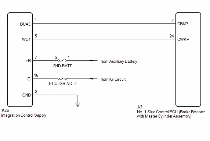
CAUTION / NOTICE / HINT
NOTICE:
- Make sure to wait 5 minutes or more with the ignition switch turned off before removing the integration control supply or disconnecting any supply power circuit from the integration control supply, in order for the voltage to be discharged and self-diagnosis to run.
- These DTCs can causes fuses to burn out, so check and replace fuses as necessary after completing inspection and repairs.
PROCEDURE
| 1. | CHECK SUB BATTERY SYSTEM |
(a) Check if sub battery system DTCs are output.
Body Electrical > Sub Battery System > Trouble Codes| Result | Proceed to |
|---|---|
| DTCs are output | A |
| DTCs are not output | B |
| A |

| INSPECT SUB BATTERY SYSTEM
|


|

| 2. | CLEAR DTC |
Pre-procedure1
(a) None
Procedure1
(b) Clear the DTCs.
Chassis > Brake Booster > Clear DTCsPost-procedure1
(c) Turn the ignition switch off.
|

| 3. | RECONFIRM DTC |
Pre-procedure1
(a) Based on the Freeze Frame Data and interview with the customer, attempt to reproduce the conditions when the malfunction occurred.
Procedure1
(b) Check if the same DTC is output.
Chassis > Brake Booster > Trouble Codes| Result | Proceed to |
|---|---|
| C125DA2 and C125DA3 are not output | A |
| C125DA2 is output | B |
| C125DA3 is output | C |
Post-procedure1
(c) None
| A |

| USE SIMULATION METHOD TO CHECK |
| C |

| GO TO STEP 6 |
|

| 4. | CHECK HARNESS, CONNECTOR AND BRAKE BOOSTER WITH MASTER CYLINDER ASSEMBLY |
Pre-procedure1
(a) Turn the ignition switch off.
Procedure1
(b) Make sure that there is no looseness at the locking part and the connecting part of the connectors.
OK:
The connector is securely connected.
Pre-procedure2
(c) Disconnect the K26 integration control supply connector.
Procedure2
(d) Check both the connector case and the terminals for deformation and corrosion.
OK:
No deformation or corrosion.
Procedure3
(e) Measure the resistance according to the value(s) in the table below.
Standard Resistance:
 Click Location & Routing(K26) Click Connector(K26)
 | Tester Connection | Condition | Specified Condition | Result |
|---|---|---|---|
| K26-1 (BUA3) - Body ground | Ignition switch OFF | 1 kΩ or higher | kΩ |
Post-procedure1
(f) None
| OK |

| REPLACE INTEGRATION CONTROL SUPPLY
|


|

| 5. | CHECK HARNESS AND CONNECTOR (BRAKE BOOSTER WITH MASTER CYLINDER ASSEMBLY - INTEGRATION CONTROL SUPPLY) |
Procedure1
(a) Make sure that there is no looseness at the locking part and the connecting part of the connectors.
OK:
The connector is securely connected.
Pre-procedure1
(b) Disconnect the A3 No. 1 skid control ECU (brake booster with master cylinder assembly) connector.
Procedure2
(c) Check both the connector case and the terminals for deformation and corrosion.
OK:
No deformation or corrosion.
Procedure3
(d) Measure the resistance according to the value(s) in the table below.
Standard Resistance:
 Click Location & Routing(A3,K26) Click Connector(A3) Click Connector(K26)
 | Tester Connection | Condition | Specified Condition | Result |
|---|---|---|---|
| A3-2 (CBKP) - K26-1 (BUA3) | Ignition switch OFF | Below 1 Ω | Ω |
| A3-2 (CBKP) or K26-1 (BUA3) - Body ground | Ignition switch OFF | 10 kΩ or higher | kΩ |
Post-procedure1
(e) None
| OK |

| REPLACE BRAKE BOOSTER WITH MASTER CYLINDER ASSEMBLY
|


| NG |

| REPAIR OR REPLACE HARNESS OR CONNECTOR |
| 6. | CHECK HARNESS, CONNECTOR AND BRAKE BOOSTER WITH MASTER CYLINDER ASSEMBLY |
Pre-procedure1
(a) Turn the ignition switch off.
Procedure1
(b) Make sure that there is no looseness at the locking part and the connecting part of the connectors.
OK:
The connector is securely connected.
Pre-procedure2
(c) Disconnect the K26 integration control supply connector.
Procedure2
(d) Check both the connector case and the terminals for deformation and corrosion.
OK:
No deformation or corrosion.
Pre-procedure3
(e) Turn the ignition switch to ON.
Procedure3
(f) Measure the voltage according to the value(s) in the table below.
Standard Voltage:
 Click Location & Routing(K26) Click Connector(K26)
 | Tester Connection | Condition | Specified Condition | Result |
|---|---|---|---|
| K26-1 (BUA3) - Body ground | Ignition switch ON | 7.5 V or less | V |
Post-procedure1
(g) None
| OK |

| REPLACE INTEGRATION CONTROL SUPPLY
|


|

| 7. | CHECK HARNESS AND CONNECTOR (BRAKE BOOSTER WITH MASTER CYLINDER ASSEMBLY - INTEGRATION CONTROL SUPPLY) |
Pre-procedure1
(a) Turn the ignition switch off.
Procedure1
(b) Make sure that there is no looseness at the locking part and the connecting part of the connectors.
OK:
The connector is securely connected.
Pre-procedure2
(c) Disconnect the A3 No. 1 skid control ECU (brake booster with master cylinder assembly) connector.
Procedure2
(d) Check both the connector case and the terminals for deformation and corrosion.
OK:
No deformation or corrosion.
Pre-procedure3
(e) Turn the ignition switch to ON.
Procedure3
(f) Measure the voltage according to the value(s) in the table below.
Standard Voltage:
 Click Location & Routing(K26) Click Connector(K26)
 | Tester Connection | Condition | Specified Condition | Result |
|---|---|---|---|
| K26-1 (BUA3) - Body ground | Ignition switch ON | 1 V or less | V |
Post-procedure1
(g) None
| OK |

| REPLACE BRAKE BOOSTER WITH MASTER CYLINDER ASSEMBLY
|


| NG |

| REPAIR OR REPLACE HARNESS OR CONNECTOR |
Reservoir Level Switch Circuit Short to Battery or Open (C126E15)
DESCRIPTION
If the No. 1 skid control ECU (brake booster with master cylinder assembly) detects that the brake fluid level is low or there is an open in the brake fluid level warning switch signal circuit, DTC C126E15 is stored.
| DTC No. | Detection Item | DTC Detection Condition | Trouble Area | MIL | DTC Output from | Priority | Note |
|---|---|---|---|---|---|---|---|
| C126E15 | Reservoir Level Switch Circuit Short to Battery or Open | The brake fluid level warning switch circuit is open for 2 seconds or more. |
| Comes on | Brake Booster | A |
|
MONITOR DESCRIPTION
When the voltage at terminal LBL of the No. 1 skid control ECU (brake booster with master cylinder assembly) is a specific value or more (open circuit judgment range) for a certain amount of time, the No. 2 skid control ECU (brake actuator assembly) judges that there is an open in the fluid level warning switch circuit and illuminates the MIL and stores this DTC.
MONITOR STRATEGY
| Related DTCs | C120F: Reservoir level switch open circuit |
| Required Sensors/Components(Main) | Brake fluid level warning switch |
| Required Sensors/Components(Related) | - |
| Frequency of Operation | Continuous |
| Duration | 2 seconds |
| MIL Operation | Immediately |
| Sequence of Operation | None |
TYPICAL ENABLING CONDITIONS
| Monitor runs whenever the following DTCs are not stored | - |
TYPICAL MALFUNCTION THRESHOLDS
| Brake fluid level warning switch open circuit signal (IC Data) | On |
COMPONENT OPERATING RANGE
| Brake fluid level warning switch open circuit signal (IC Data) | Off |
CONFIRMATION DRIVING PATTERN
NOTICE:
When performing the normal judgment procedure, make sure that the driver door is closed and is not opened at any time during the procedure.
HINT:
- After repair has been completed, clear the DTC and then check that the Toyota Prius vehicle has returned to normal by performing the following All Readiness check procedure.
- When clearing the permanent DTCs, refer to the "CLEAR PERMANENT DTC" procedure.
- Connect the GTS to the DLC3.
- Turn the ignition switch to ON and turn the GTS on.
- Clear the DTCs (even if no DTCs are stored, perform the clear DTC procedure).
- Turn the ignition switch off.
- Turn the ignition switch to ON (READY) and turn the GTS on.
-
Wait for 3 seconds or more. [*]
HINT:
[*]: Normal judgment procedure.
The normal judgment procedure is used to complete DTC judgment and also used when clearing permanent DTCs.
-
Enter the following menus: Chassis / Brake/EPB* / Utility / All Readiness.
*: Electric Parking Brake System
-
Check the DTC judgment result.
HINT:
- If the judgment result shows NORMAL, the system is normal.
- If the judgment result shows ABNORMAL, the system has a malfunction.
- If the judgment result shows INCOMPLETE, perform driving pattern again.
WIRING DIAGRAM
Refer to DTC C120200.
Click here

CAUTION / NOTICE / HINT
NOTICE:
Make sure to wait 5 minutes or more with the ignition switch turned off before removing the integration control supply or disconnecting any supply power circuit from the integration control supply, in order for the voltage to be discharged and self-diagnosis to run.
PROCEDURE
| 1. | CHECK BRAKE FLUID LEVEL |
(a) Check that the brake fluid level is sufficient.
HINT:
If the fluid level is low, check for fluid leaks, and repair as necessary.
(1) Check for brake fluid leaks (connection between the brake actuator assembly, brake booster with master cylinder assembly and wheel cylinders).
HINT:
If no leaks exist, add and adjust fluid using the GTS.
Click here

| NG |

| CHECK AND REPAIR BRAKE FLUID LEAKS OR ADD FLUID |
|

| 2. | INSPECT BRAKE FLUID LEVEL WARNING SWITCH |
Pre-procedure1
(a) Turn the ignition switch off.
Procedure1
(b) Inspect the brake fluid level warning switch.
Click here

OK:
The brake fluid level warning switch is normal.
Post-procedure1
(c) None
| NG |

| REPLACE BRAKE BOOSTER WITH MASTER CYLINDER ASSEMBLY
|


|

| 3. | CHECK HARNESS AND CONNECTOR (BRAKE BOOSTER WITH MASTER CYLINDER ASSEMBLY - BRAKE FLUID LEVEL WARNING SWITCH) |
Pre-procedure1
(a) Turn the ignition switch off.
Procedure1
(b) Make sure that there is no looseness at the locking part and the connecting part of the connector.
OK:
The connector is securely connected.
Pre-procedure2
(c) Disconnect the A3 No. 1 skid control ECU (brake booster with master cylinder assembly) connector.
Procedure2
(d) Check both the connector case and the terminals for deformation and corrosion.
OK:
No deformation or corrosion.
Procedure3
(e) Measure the resistance according to the value(s) in the table below.
Standard Resistance:
 Click Location & Routing(A3,A6) Click Connector(A3) Click Connector(A6)
 | Tester Connection | Condition | Specified Condition | Result |
|---|---|---|---|
| A3-23 (LBL) - A6-2 (LBL) | Always | Below 1 Ω | Ω |
| A3-23 (LBL) or A6-2 (LBL) - Body ground | Always | 10 kΩ or higher | kΩ |
| A6-1 (GND) - Body ground | 1 minute or more after disconnecting the cable from the negative (-) auxiliary battery terminal | Below 1 Ω | Ω |
Post-procedure1
(f) None
| NG |

| REPAIR OR REPLACE HARNESS OR CONNECTOR |
|

| 4. | CHECK BRAKE DISC |
Pre-procedure1
(a) Reconnect the A3 No. 1 skid control ECU (brake booster with master cylinder assembly) connector.
(b) Reconnect the A6 brake fluid level warning switch connector.
(c) Disconnect the A5 brake pedal stroke sensor assembly connector.
Procedure1
(d) Perform a road test according to Freeze Frame Data or customer problem analysis. While driving, check for abnormal brake pedal vibration caused by brake discs that are worn or have excess runout.
OK:
Brake pedal does not vibrate during braking.
HINT:
- An unevenly worn disc may vibrate the caliper pistons and cause fluctuations in brake line pressure, triggering a malfunction detection condition.
- The brake pedal does not kick back due to caliper piston vibration during electronically controlled brake system control.
- If the brake pedal stroke sensor assembly connector is disconnected, the fail-safe function will prohibit electronically controlled brake system control.
- The Active Test does not prohibit electronically controlled brake system control when the Toyota Prius vehicle is being driven, so disconnect the brake pedal stroke sensor assembly connector before continuing with inspection.
-
Uneven disc wear can be checked by measuring the disc thickness variation.
for Front Brake: Click here


for Rear Brake: Click here

Post-procedure1
(e) None
| NG |

| REPLACE BRAKE DISC |
|

| 5. | CLEAR DTC |
Pre-procedure1
(a) Turn the ignition switch off.
(b) Reconnect the A5 brake pedal stroke sensor assembly connector.
Procedure1
(c) Clear the DTCs.
Chassis > Brake Booster > Clear DTCsPost-procedure1
(d) Turn the ignition switch off.
|

| 6. | RECONFIRM DTC |
Pre-procedure1
(a) Based on the Freeze Frame Data and interview with the customer, attempt to reproduce the conditions when the malfunction occurred.
Procedure1
(b) Check if the same DTC is output.
Chassis > Brake Booster > Trouble Codes| Result | Proceed to |
|---|---|
| C126E15 is not output | A |
| C126E15 is output | B |
Post-procedure1
(c) None
| A |

| USE SIMULATION METHOD TO CHECK |
| B |

| REPLACE BRAKE BOOSTER WITH MASTER CYLINDER ASSEMBLY
|


Electronic Brake Booster Motor "A" Position Sensor Signal Cross Coupled (C129A2B)
DESCRIPTION
The pump motor is built into the No. 1 skid control ECU (brake booster with master cylinder assembly). The pump motor is controlled using the rotation angle sensor, and so the sensor value is monitored to detect malfunctions.
| DTC No. | Detection Item | DTC Detection Condition | Trouble Area | MIL | DTC Output from | Priority | Note |
|---|---|---|---|---|---|---|---|
| C129A2B | Electronic Brake Booster Motor "A" Position Sensor Signal Cross Coupled | When rotation angle sensor malfunction status continues. | No. 1 skid control ECU (brake booster with master cylinder assembly) | Comes on | Brake Booster | A |
|
MONITOR DESCRIPTION
The pump motor is built into the No. 1 skid control ECU (brake booster with master cylinder assembly).
With the Toyota Prius vehicle power source voltage normal, voltage applied normally to the motor power source terminal and the No. 1 skid control ECU (brake booster with master cylinder assembly) started, if the hall sensor U, V and W phase output pattern during motor rotation is an unanticipated output, the No. 2 skid control ECU (brake actuator assembly) determines that there is a pump motor drive circuit malfunction, the MIL is illuminated and a DTC is stored.
MONITOR STRATEGY
| Related DTCs | C129B: Rotation angle sensor range/performance |
| Required Sensors/Components(Main) | No. 2 skid control ECU (brake actuator assembly) Brake booster with master cylinder assembly |
| Required Sensors/Components(Related) | Brake pedal stroke sensor assembly No. 2 skid control ECU (brake actuator assembly) Brake booster with master cylinder assembly |
| Frequency of Operation | Continuous |
| Duration | - |
| MIL Operation | Immediately |
| Sequence of Operation | None |
TYPICAL ENABLING CONDITIONS
| Monitor runs whenever the following DTCs are not stored | C1100 (Case 1): Brake pedal position sensor voltage circuit/open C12B4 (Case 2): Brake booster motor performance (motor current) C12BF (Case 1 to 4): Brake booster motor performance (motor upper circuit) C12BF (Case 5 to 9): Brake booster motor performance (motor drive circuit) C14C8: Brake system voltage circuit high |
| All of the following conditions are met | A, B, C, D, E, F and G |
| A. Both of the following conditions are met | More than 0.198 seconds |
| BS cut MOS | Valid |
| BS cut MOS voltage | Below 23.2 V |
| B. Both of the following conditions are met | More than 0.198 seconds |
| BS cut MOS | Valid |
| BS cut MOS voltage | Higher than 7.4 V |
| C. Following condition is met | More than 0.198 seconds |
| BM voltage | 7.1 V or higher |
| D. Command to motor failsafe relay | On |
| E. Brake pedal position sensor1 power supply | 4.8 V or higher, and 5.2 V or less |
| F. VCSK | Valid |
| G. BS cut MOS voltage | Higher than 7.8 V |
TYPICAL MALFUNCTION THRESHOLDS
| Either of the following conditions is met | A or B |
| A. Following condition is met | More than 10 times |
| Hall sensor pattern sequence | Abnormal |
| B. Following condition is met | More than 0.072 seconds |
| Hall sensor undefined pattern | - |
COMPONENT OPERATING RANGE
| All of the following conditions are met | A, B, C, D, E, F and G |
| A. Both of the following conditions are met | More than 0.198 seconds |
| BS cut MOS | Valid |
| BS cut MOS voltage | Below 23.2 V |
| B. Both of the following conditions are met | More than 0.198 seconds |
| BS cut MOS | Valid |
| BS cut MOS voltage | Higher than 7.4 V |
| C. Following condition is met | More than 0.198 seconds |
| BM voltage | 7.1 V or higher |
| D. Command to motor failsafe relay | On |
| E. Brake pedal position sensor1 power supply | 4.8 V or higher, and 5.2 V or less |
| F. VCSK | Valid |
| G. Following condition is met | 0 times |
| Hall sensor pattern sequence | Abnormal |
CONFIRMATION DRIVING PATTERN
NOTICE:
When performing the normal judgment procedure, make sure that the driver door is closed and is not opened at any time during the procedure.
HINT:
- After repair has been completed, clear the DTC and then check that the Toyota Prius vehicle has returned to normal by performing the following All Readiness check procedure.
- When clearing the permanent DTCs, refer to the "CLEAR PERMANENT DTC" procedure.
- Connect the GTS to the DLC3.
- Turn the ignition switch to ON and turn the GTS on.
- Clear the DTCs (even if no DTCs are stored, perform the clear DTC procedure).
- Turn the ignition switch off.
- Turn the ignition switch to ON (READY) and turn the GTS on.
-
Wait for 2 seconds or more. [*]
HINT:
[*]: Normal judgment procedure.
The normal judgment procedure is used to complete DTC judgment and also used when clearing permanent DTCs.
-
Enter the following menus: Chassis / Brake/EPB* / Utility / All Readiness.
*: Electric Parking Brake System
-
Check the DTC judgment result.
HINT:
- If the judgment result shows NORMAL, the system is normal.
- If the judgment result shows ABNORMAL, the system has a malfunction.
- If the judgment result shows INCOMPLETE, perform driving pattern again.
PROCEDURE
| 1. | REPLACE BRAKE BOOSTER WITH MASTER CYLINDER ASSEMBLY |
HINT:
Click here


| NEXT |

| END |
Left Front Wheel ABS Hold Solenoid Control Circuit Short to Battery (C12A512,...,C12B014)
DESCRIPTION
The solenoid relay and solenoid valves are built into the brake actuator assembly.
The front solenoid valve LH controls the brake fluid pressure of the front wheel cylinder LH of the vehicle.
When these DTCs are stored, the fail-safe function operates and the solenoid relay is turned off to prevent the solenoid valves from operating.
| DTC No. | Detection Item | DTC Detection Condition | Trouble Area | MIL | DTC Output from | Priority | Note |
|---|---|---|---|---|---|---|---|
| C12A512 | Left Front Wheel ABS Hold Solenoid Control Circuit Short to Battery | An excessive current is detected in the solenoid for 0.05 seconds or more. | No. 2 skid control ECU (brake actuator assembly) | Comes on | Brake/EPB | A |
|
| C12A514 | Left Front Wheel ABS Hold Solenoid Control Circuit Short to Ground or Open | Insufficient current is detected in the solenoid for 0.05 seconds or more. | No. 2 skid control ECU (brake actuator assembly) | Comes on | Brake/EPB | A |
|
| C12A518 | Left Front Wheel ABS Hold Solenoid Control Circuit Current Below Threshold | An open is detected in the solenoid for 0.05 seconds or more. | No. 2 skid control ECU (brake actuator assembly) | Comes on | Brake/EPB | A |
|
| C12A519 | Left Front Wheel ABS Hold Solenoid Control Circuit Current Above Threshold | Overcurrent is detected in the solenoid for 0.05 seconds or more. | No. 2 skid control ECU (brake actuator assembly) | Comes on | Brake/EPB | A |
|
| C12A51D | Left Front Wheel ABS Hold Solenoid Control Circuit Current Out of Range | Current leakage is detected in the solenoid for 0.05 seconds or more. | No. 2 skid control ECU (brake actuator assembly) | Comes on | Brake/EPB | A |
|
| C12B012 | Left Front Wheel ABS Release Solenoid Control Circuit Short to Battery | Any of the following is detected:
| No. 2 skid control ECU (brake actuator assembly) | Comes on | Brake/EPB | A |
|
| C12B014 | Left Front Wheel ABS Release Solenoid Control Circuit Short to Ground or Open | Any of the following is detected:
| No. 2 skid control ECU (brake actuator assembly) | Comes on | Brake/EPB | A |
|
MONITOR DESCRIPTION
The No. 2 skid control ECU (brake actuator assembly) monitors the drive voltage and current of the ABS holding solenoid and ABS reduction solenoid. Based on the monitored information, if any of the following abnormal conditions are detected, the MIL is illuminated and a DTC is stored.
- Excessively high current in a solenoid circuit is detected
- Excessively low current in a solenoid circuit is detected
- An open in a solenoid circuit is detected
- Overcurrent in a solenoid circuit is detected
- A current leak in a solenoid circuit is detected
- Excessively high temperature in a solenoid is detected
- An abnormal solenoid circuit is detected
MONITOR STRATEGY
| Related DTCs | C12A7 (Case 1 and 2): ABS hold solenoid (FL) circuit open C12A7 (Case 3): ABS hold solenoid (FL) circuit low C12A8 (Case 1): ABS hold solenoid (FL) circuit high (solenoid Off current) C12A8 (Case 2 and 3): ABS hold solenoid (FL) circuit high (IC data) C12A8 (Case 4): ABS hold solenoid (FL) circuit high (solenoid On current) C12B2: ABS release solenoid (FL) circuit low C12B3: ABS release solenoid (FL) circuit high |
| Required Sensors/Components(Main) | No. 2 skid control ECU (brake actuator assembly) |
| Required Sensors/Components(Related) | No. 2 skid control ECU (brake actuator assembly) |
| Frequency of Operation | Continuous |
| Duration | 0.054 seconds: C12A7, C12A8 (Case 1 to 3), C12B2 and C12B3 -: C12A8 (Case 4) |
| MIL Operation | Immediately |
| Sequence of Operation | None |
TYPICAL ENABLING CONDITIONS
C12A7 (Case 1)| Monitor runs whenever the following DTCs are not stored | C0597: ABS hold solenoid performance C12A8 (Case 1): ABS hold solenoid (FL) circuit high (solenoid Off current) C12A8 (Case 2 and 3): ABS hold solenoid (FL) circuit high (IC data) C12A8 (Case 4): ABS hold solenoid (FL) circuit high (solenoid On current) C12B2: ABS release solenoid (FL) circuit low C12B3: ABS release solenoid (FL) circuit high C12BD (Case 1 and 2): ABS hold solenoid (FR) circuit open C12BD (Case 3): ABS hold solenoid (FR) circuit low C12BE (Case 1): ABS hold solenoid (FR) circuit high (solenoid Off current) C12BE (Case 2 and 3): ABS hold solenoid (FR) circuit high (IC data) C12BE (Case 4): ABS hold solenoid (FR) circuit high (solenoid On current) C12C8: ABS release solenoid (FR) circuit low C12C9: ABS release solenoid (FR) circuit high C12D3 (Case 1 and 2): ABS hold solenoid (RL) circuit open C12D3 (Case 3): ABS hold solenoid (RL) circuit low C12D4 (Case 1): ABS hold solenoid (RL) circuit high (solenoid Off current) C12D4 (Case 2 and 3): ABS hold solenoid (RL) circuit high (IC data) C12D4 (Case 4): ABS hold solenoid (RL) circuit high (solenoid On current) C12DE: ABS release solenoid (RL) circuit low C12DF: ABS release solenoid (RL) circuit high C12E9 (Case 1 and 2): ABS hold solenoid (RR) circuit open C12E9 (Case 3): ABS hold solenoid (RR) circuit low C12EA (Case 1): ABS hold solenoid (RR) circuit high (solenoid Off current) C12EA (Case 2 and 3): ABS hold solenoid (RR) circuit high (IC data) C12EA (Case 4): ABS hold solenoid (RR) circuit high (solenoid On current) C12F4: ABS release solenoid (RR) circuit low C12F5: ABS release solenoid (RR) circuit high C12F6: ABS hold solenoid other functional C12F7: ABS hold solenoid other functional C13BF: SM solenoid other functional C13C2 (Case 1 and 2): SM1 solenoid circuit open C13C2 (Case 3): SM1 solenoid circuit low C13C3 (Case 1): SM1 solenoid circuit high (solenoid Off current) C13C3 (Case 2 and 3): SM1 solenoid circuit high (IC data) C13C3 (Case 4): SM1 solenoid circuit high (solenoid On current) C13CB (Case 1 and 2): SM2 solenoid circuit open C13CB (Case 3): SM2 solenoid circuit low C13CC (Case 1): SM2 solenoid circuit high (solenoid Off current) C13CC (Case 2 and 3): SM2 solenoid circuit high (IC data) C13CC (Case 4): SM2 solenoid circuit high (solenoid On current) C137D: Brake system voltage circuit high C143B: Brake system voltage power supply relay circuit high C143C: Brake system voltage power supply relay circuit open |
| All of the following conditions are met | A, B, C, D, E and F |
| A. Command to solenoid relay | On |
| B. Following condition is met | More than 0.012 seconds |
| AST voltage | 6 V or higher |
| C. Following condition is met | More than 0.22 seconds |
| BS voltage | 17.4 V or less |
| D. BS voltage | 9.5 V or higher |
| E. IGR voltage | Higher than 10 V |
| F. IGP voltage | Higher than 10 V |
| Monitor runs whenever the following DTCs are not stored | C0597: ABS hold solenoid circuit stuck C12A8 (Case 1): ABS hold solenoid (FL) circuit high (solenoid Off current) C12A8 (Case 2 and 3): ABS hold solenoid (FL) circuit high (IC data) C12A8 (Case 4): ABS hold solenoid (FL) circuit high (solenoid On current) C12B2: ABS release solenoid (FL) circuit low C12B3: ABS release solenoid (FL) circuit high C12BD (Case 1 and 2): ABS hold solenoid (FR) circuit open C12BD (Case 3): ABS hold solenoid (FR) circuit low C12BE (Case 1): ABS hold solenoid (FR) circuit high (solenoid Off current) C12BE (Case 2 and 3): ABS hold solenoid (FR) circuit high (IC data) C12BE (Case 4): ABS hold solenoid (FR) circuit high (solenoid On current) C12C8: ABS release solenoid (FR) circuit low C12C9: ABS release solenoid (FR) circuit high C12D3 (Case 1 and 2): ABS hold solenoid (RL) circuit open C12D3 (Case 3): ABS hold solenoid (RL) circuit low C12D4 (Case 1): ABS hold solenoid (RL) circuit high (solenoid Off current) C12D4 (Case 2 and 3): ABS hold solenoid (RL) circuit high (IC data) C12D4 (Case 4): ABS hold solenoid (RL) circuit high (solenoid On current) C12DE: ABS release solenoid (RL) circuit low C12DF: ABS release solenoid (RL) circuit high C12E9 (Case 1 and 2): ABS hold solenoid (RR) circuit open C12E9 (Case 3): ABS hold solenoid (RR) circuit low C12EA (Case 1): ABS hold solenoid (RR) circuit high (solenoid Off current) C12EA (Case 2 and 3): ABS hold solenoid (RR) circuit high (IC data) C12EA (Case 4): ABS hold solenoid (RR) circuit high (solenoid On current) C12F4: ABS release solenoid (RR) circuit low C12F5: ABS release solenoid (RR) circuit high C12F6: ABS hold solenoid other functional C12F7: ABS hold solenoid other functional C13BF: SM solenoid other functional C13C2 (Case 1 and 2): SM1 solenoid circuit open C13C2 (Case 3): SM1 solenoid circuit low C13C3 (Case 1): SM1 solenoid circuit high (solenoid Off current) C13C3 (Case 2 and 3): SM1 solenoid circuit high (IC data) C13C3 (Case 4): SM1 solenoid circuit high (solenoid On current) C13CB (Case 1 and 2): SM2 solenoid circuit open C13CB (Case 3): SM2 solenoid circuit low C13CC (Case 1): SM2 solenoid circuit high (solenoid Off current) C13CC (Case 2 and 3): SM2 solenoid circuit high (IC data) C13CC (Case 4): SM2 solenoid circuit high (solenoid On current) C137D: Brake system voltage circuit high C143B: Brake system voltage power supply relay circuit high C143C: Brake system voltage power supply relay circuit open |
| All of the following conditions are met | A, B, C, D, E, F and G |
| A. Command to solenoid relay | On |
| B. Following condition is met | More than 0.012 seconds |
| AST voltage | 6 V or higher |
| C. Following condition is met | More than 0.22 seconds |
| BS voltage | 17.4 V or less |
| D. Following condition is met | More than 0.054 seconds |
| Solenoid target current value | 0 A |
| E. BS voltage | 9.5 V or higher |
| F. IGR voltage | Higher than 10 V |
| G. IGP voltage | Higher than 10 V |
| Monitor runs whenever the following DTCs are not stored | C0597: ABS hold solenoid performance C12A8 (Case 1): ABS hold solenoid (FL) circuit high (solenoid Off current) C12A8 (Case 2 and 3): ABS hold solenoid (FL) circuit high (IC data) C12A8 (Case 4): ABS hold solenoid (FL) circuit high (solenoid On current) C12B2: ABS release solenoid (FL) circuit low C12B3: ABS release solenoid (FL) circuit high C12BD (Case 1 and 2): ABS hold solenoid (FR) circuit open C12BD (Case 3): ABS hold solenoid (FR) circuit low C12BE (Case 1): ABS hold solenoid (FR) circuit high (solenoid Off current) C12BE (Case 2 and 3): ABS hold solenoid (FR) circuit high (IC data) C12BE (Case 4): ABS hold solenoid (FR) circuit high (solenoid On current) C12C8: ABS release solenoid (FR) circuit low C12C9: ABS release solenoid (FR) circuit high C12D3 (Case 1 and 2): ABS hold solenoid (RL) circuit open C12D3 (Case 3): ABS hold solenoid (RL) circuit low C12D4 (Case 1): ABS hold solenoid (RL) circuit high (solenoid Off current) C12D4 (Case 2 and 3): ABS hold solenoid (RL) circuit high (IC data) C12D4 (Case 4): ABS hold solenoid (RL) circuit high (solenoid On current) C12DE: ABS release solenoid (RL) circuit low C12DF: ABS release solenoid (RL) circuit high C12E9 (Case 1 and 2): ABS hold solenoid (RR) circuit open C12E9 (Case 3): ABS hold solenoid (RR) circuit low C12EA (Case 1): ABS hold solenoid (RR) circuit high (solenoid Off current) C12EA (Case 2 and 3): ABS hold solenoid (RR) circuit high (IC data) C12EA (Case 4): ABS hold solenoid (RR) circuit high (solenoid On current) C12F4: ABS release solenoid (RR) circuit low C12F5: ABS release solenoid (RR) circuit high C12F6: ABS hold solenoid other functional C12F7: ABS hold solenoid other functional C13BF: SM solenoid other functional C13C2 (Case 1 and 2): SM1 solenoid circuit open C13C2 (Case 3): SM1 solenoid circuit low C13C3 (Case 1): SM1 solenoid circuit high (solenoid Off current) C13C3 (Case 2 and 3): SM1 solenoid circuit high (IC data) C13C3 (Case 4): SM1 solenoid circuit high (solenoid On current) C13CB (Case 1 and 2): SM2 solenoid circuit open C13CB (Case 3): SM2 solenoid circuit low C13CC (Case 1): SM2 solenoid circuit high (solenoid Off current) C13CC (Case 2 and 3): SM2 solenoid circuit high (IC data) C13CC (Case 4): SM2 solenoid circuit high (solenoid On current) C137D: Brake system voltage circuit high C143B: Brake system voltage power supply relay circuit high C143C: Brake system voltage power supply relay circuit open |
| All of the following conditions are met | A, B, C, D, E, F, G, H, I, J and K |
| A. Command to solenoid relay | On |
| B. Following condition is met | More than 0.012 seconds |
| AST voltage | 9.5 V or higher |
| C. Following condition is met | More than 0.22 seconds |
| BS voltage | 17.4 V or less |
| D. Following condition is met | More than 0.048 seconds |
| Solenoid target current value | 0.25 A or higher |
| E. Solenoid overcurrent signal (IC Data) | Off |
| F. Solenoid driver overtemperature signal (IC Data) | Off |
| G. Solenoid return current terminal disconnection signal (IC Data) | Off |
| H. Solenoid GND terminal disconnection signal (IC Data) | Off |
| I. BS voltage | 9.5 V or higher |
| J. IGR voltage | Higher than 10 V |
| K. IGP voltage | Higher than 10 V |
| Monitor runs whenever the following DTCs are not stored | C0597: ABS hold solenoid performance C12A7 (Case 1 and 2): ABS hold solenoid (FL) circuit open C12A7 (Case 3): ABS hold solenoid (FL) circuit low C12B2: ABS release solenoid (FL) circuit low C12B3: ABS release solenoid (FL) circuit high C12BD (Case 1 and 2): ABS hold solenoid (FR) circuit open C12BD (Case 3): ABS hold solenoid (FR) circuit low C12BE (Case 1): ABS hold solenoid (FR) circuit high (solenoid Off current) C12BE (Case 2 and 3): ABS hold solenoid (FR) circuit high (IC data) C12BE (Case 4): ABS hold solenoid (FR) circuit high (solenoid On current) C12C8: ABS release solenoid (FR) circuit low C12C9: ABS release solenoid (FR) circuit high C12D3 (Case 1 and 2): ABS hold solenoid (RL) circuit open C12D3 (Case 3): ABS hold solenoid (RL) circuit low C12D4 (Case 1): ABS hold solenoid (RL) circuit high (solenoid Off current) C12D4 (Case 2 and 3): ABS hold solenoid (RL) circuit high (IC data) C12D4 (Case 4): ABS hold solenoid (RL) circuit high (solenoid On current) C12DE: ABS release solenoid (RL) circuit low C12DF: ABS release solenoid (RL) circuit high C12E9 (Case 1 and 2): ABS hold solenoid (RR) circuit open C12E9 (Case 3): ABS hold solenoid (RR) circuit low C12EA (Case 1): ABS hold solenoid (RR) circuit high (solenoid Off current) C12EA (Case 2 and 3): ABS hold solenoid (RR) circuit high (IC data) C12EA (Case 4): ABS hold solenoid (RR) circuit high (solenoid On current) C12F4: ABS release solenoid (RR) circuit low C12F5: ABS release solenoid (RR) circuit high C12F6: ABS hold solenoid other functional C12F7: ABS hold solenoid other functional C13BF: SM solenoid other functional C13C2 (Case 1 and 2): SM1 solenoid circuit open C13C2 (Case 3): SM1 solenoid circuit low C13C3 (Case 1): SM1 solenoid circuit high (solenoid Off current) C13C3 (Case 2 and 3): SM1 solenoid circuit high (IC data) C13C3 (Case 4): SM1 solenoid circuit high (solenoid On current) C13CB (Case 1 and 2): SM2 solenoid circuit open C13CB (Case 3): SM2 solenoid circuit low C13CC (Case 1): SM2 solenoid circuit high (solenoid Off current) C13CC (Case 2 and 3): SM2 solenoid circuit high (IC data) C13CC (Case 4): SM2 solenoid circuit high (solenoid On current) C137D: Brake system voltage circuit high C143B: Brake system voltage power supply relay circuit high C143C: Brake system voltage power supply relay circuit open |
| All of the following conditions are met | A, B, C, D, E, F, G, H, I, J, K, L and M |
| A. Command to solenoid relay | On |
| B. Following condition is met | More than 0.012 seconds |
| AST voltage | 6 V or higher |
| C. Following condition is met | More than 0.054 seconds |
| Solenoid target current value | 0 A |
| D. Following condition is met | More than 0.22 seconds |
| BS voltage | 17.4 V or less |
| E. Solenoid overcurrent signal (IC Data) | Off |
| F. Solenoid driver overtemperature signal (IC Data) | Off |
| G. Solenoid load open/short to ground signal (IC Data) | Off |
| H. Solenoid load leakage signal (IC Data) | Off |
| I. Solenoid return current terminal disconnection signal (IC Data) | Off |
| J. Solenoid GND terminal disconnection signal (IC Data) | Off |
| K. BS voltage | 9.5 V or higher |
| L. IGR voltage | Higher than 10 V |
| M. IGP voltage | Higher than 10 V |
| Monitor runs whenever the following DTCs are not stored | C0597: ABS hold solenoid performance C12A7 (Case 1 and 2): ABS hold solenoid (FL) circuit open C12A7 (Case 3): ABS hold solenoid (FL) circuit low C12B2: ABS release solenoid (FL) circuit low C12B3: ABS release solenoid (FL) circuit high C12BD (Case 1 and 2): ABS hold solenoid (FR) circuit open C12BD (Case 3): ABS hold solenoid (FR) circuit low C12BE (Case 1): ABS hold solenoid (FR) circuit high (solenoid Off current) C12BE (Case 2 and 3): ABS hold solenoid (FR) circuit high (IC data) C12BE (Case 4): ABS hold solenoid (FR) circuit high (solenoid On current) C12C8: ABS release solenoid (FR) circuit low C12C9: ABS release solenoid (FR) circuit high C12D3 (Case 1 and 2): ABS hold solenoid (RL) circuit open C12D3 (Case 3): ABS hold solenoid (RL) circuit low C12D4 (Case 1): ABS hold solenoid (RL) circuit high (solenoid Off current) C12D4 (Case 2 and 3): ABS hold solenoid (RL) circuit high (IC data) C12D4 (Case 4): ABS hold solenoid (RL) circuit high (solenoid On current) C12DE: ABS release solenoid (RL) circuit low C12DF: ABS release solenoid (RL) circuit high C12E9 (Case 1 and 2): ABS hold solenoid (RR) circuit open C12E9 (Case 3): ABS hold solenoid (RR) circuit low C12EA (Case 1): ABS hold solenoid (RR) circuit high (solenoid Off current) C12EA (Case 2 and 3): ABS hold solenoid (RR) circuit high (IC data) C12EA (Case 4): ABS hold solenoid (RR) circuit high (solenoid On current) C12F4: ABS release solenoid (RR) circuit low C12F5: ABS release solenoid (RR) circuit high C12F6: ABS hold solenoid other functional C12F7: ABS hold solenoid other functional C13BF: SM solenoid other functional C13C2 (Case 1 and 2): SM1 solenoid circuit open C13C2 (Case 3): SM1 solenoid circuit low C13C3 (Case 1): SM1 solenoid circuit high (solenoid Off current) C13C3 (Case 2 and 3): SM1 solenoid circuit high (IC data) C13C3 (Case 4): SM1 solenoid circuit high (solenoid On current) C13CB (Case 1 and 2): SM2 solenoid circuit open C13CB (Case 3): SM2 solenoid circuit low C13CC (Case 1): SM2 solenoid circuit high (solenoid Off current) C13CC (Case 2 and 3): SM2 solenoid circuit high (IC data) C13CC (Case 4): SM2 solenoid circuit high (solenoid On current) C137D: Brake system voltage circuit high C143B: Brake system voltage power supply relay circuit high C143C: Brake system voltage power supply relay circuit open |
| All of the following conditions are met | A, B, C, D, E and F |
| A. Command to solenoid relay | On |
| B. Following condition is met | More than 0.012 seconds |
| AST voltage | 6 V or higher |
| C. Following condition is met | More than 0.22 seconds |
| BS voltage | 17.4 V or less |
| D. BS voltage | 9.5 V or higher |
| E. IGR voltage | Higher than 10 V |
| F. IGP voltage | Higher than 10 V |
| Monitor runs whenever the following DTCs are not stored | C0597: ABS hold solenoid performance C12A7 (Case 1 and 2): ABS hold solenoid (FL) circuit open C12A7 (Case 3): ABS hold solenoid (FL) circuit low C12B2: ABS release solenoid (FL) circuit low C12B3: ABS release solenoid (FL) circuit high C12BD (Case 1 and 2): ABS hold solenoid (FR) circuit open C12BD (Case 3): ABS hold solenoid (FR) circuit low C12BE (Case 1): ABS hold solenoid (FR) circuit high (solenoid Off current) C12BE (Case 2 and 3): ABS hold solenoid (FR) circuit high (IC data) C12BE (Case 4): ABS hold solenoid (FR) circuit high (solenoid On current) C12C8: ABS release solenoid (FR) circuit low C12C9: ABS release solenoid (FR) circuit high C12D3 (Case 1 and 2): ABS hold solenoid (RL) circuit open C12D3 (Case 3): ABS hold solenoid (RL) circuit low C12D4 (Case 1): ABS hold solenoid (RL) circuit high (solenoid Off current) C12D4 (Case 2 and 3): ABS hold solenoid (RL) circuit high (IC data) C12D4 (Case 4): ABS hold solenoid (RL) circuit high (solenoid On current) C12DE: ABS release solenoid (RL) circuit low C12DF: ABS release solenoid (RL) circuit high C12E9 (Case 1 and 2): ABS hold solenoid (RR) circuit open C12E9 (Case 3): ABS hold solenoid (RR) circuit low C12EA (Case 1): ABS hold solenoid (RR) circuit high (solenoid Off current) C12EA (Case 2 and 3): ABS hold solenoid (RR) circuit high (IC data) C12EA (Case 4): ABS hold solenoid (RR) circuit high (solenoid On current) C12F4: ABS release solenoid (RR) circuit low C12F5: ABS release solenoid (RR) circuit high C12F6: ABS hold solenoid other functional C12F7: ABS hold solenoid other functional C13BF: SM solenoid other functional C13C2 (Case 1 and 2): SM1 solenoid circuit open C13C2 (Case 3): SM1 solenoid circuit low C13C3 (Case 1): SM1 solenoid circuit high (solenoid Off current) C13C3 (Case 2 and 3): SM1 solenoid circuit high (IC data) C13C3 (Case 4): SM1 solenoid circuit high (solenoid On current) C13CB (Case 1 and 2): SM2 solenoid circuit open C13CB (Case 3): SM2 solenoid circuit low C13CC (Case 1): SM2 solenoid circuit high (solenoid Off current) C13CC (Case 2 and 3): SM2 solenoid circuit high (IC data) C13CC (Case 4): SM2 solenoid circuit high (solenoid On current) C137D: Brake system voltage circuit high C143B: Brake system voltage power supply relay circuit high C143C: Brake system voltage power supply relay circuit open |
| All of the following conditions are met | A, B, C, D, E, F and G |
| A. Command to solenoid relay | On |
| B. Following condition is met | More than 0.012 seconds |
| AST voltage | 6 V or higher |
| C. Following condition is met | More than 0.22 seconds |
| BS voltage | 17.4 V or less |
| D. Following condition is met | More than 0.054 seconds |
| Solenoid target current value | 0 A |
| E. BS voltage | 9.5 V or higher |
| F. IGR voltage | Higher than 10 V |
| G. IGP voltage | Higher than 10 V |
| Monitor runs whenever the following DTCs are not stored | C0597: ABS hold solenoid performance C12A7 (Case 1 and 2): ABS hold solenoid (FL) circuit open C12A7 (Case 3): ABS hold solenoid (FL) circuit low C12B2: ABS release solenoid (FL) circuit low C12B3: ABS release solenoid (FL) circuit high C12BD (Case 1 and 2): ABS hold solenoid (FR) circuit open C12BD (Case 3): ABS hold solenoid (FR) circuit low C12BE (Case 1): ABS hold solenoid (FR) circuit high (solenoid Off current) C12BE (Case 2 and 3): ABS hold solenoid (FR) circuit high (IC data) C12BE (Case 4): ABS hold solenoid (FR) circuit high (solenoid On current) C12C8: ABS release solenoid (FR) circuit low C12C9: ABS release solenoid (FR) circuit high C12D3 (Case 1 and 2): ABS hold solenoid (RL) circuit open C12D3 (Case 3): ABS hold solenoid (RL) circuit low C12D4 (Case 1): ABS hold solenoid (RL) circuit high (solenoid Off current) C12D4 (Case 2 and 3): ABS hold solenoid (RL) circuit high (IC data) C12D4 (Case 4): ABS hold solenoid (RL) circuit high (solenoid On current) C12DE: ABS release solenoid (RL) circuit low C12DF: ABS release solenoid (RL) circuit high C12E9 (Case 1 and 2): ABS hold solenoid (RR) circuit open C12E9 (Case 3): ABS hold solenoid (RR) circuit low C12EA (Case 1): ABS hold solenoid (RR) circuit high (solenoid Off current) C12EA (Case 2 and 3): ABS hold solenoid (RR) circuit high (IC data) C12EA (Case 4): ABS hold solenoid (RR) circuit high (solenoid On current) C12F4: ABS release solenoid (RR) circuit low C12F5: ABS release solenoid (RR) circuit high C12F6: ABS hold solenoid other functional C12F7: ABS hold solenoid other functional C13BF: SM solenoid other functional C13C2 (Case 1 and 2): SM1 solenoid circuit open C13C2 (Case 3): SM1 solenoid circuit low C13C3 (Case 1): SM1 solenoid circuit high (solenoid Off current) C13C3 (Case 2 and 3): SM1 solenoid circuit high (IC data) C13C3 (Case 4): SM1 solenoid circuit high (solenoid On current) C13CB (Case 1 and 2): SM2 solenoid circuit open C13CB (Case 3): SM2 solenoid circuit low C13CC (Case 1): SM2 solenoid circuit high (solenoid Off current) C13CC (Case 2 and 3): SM2 solenoid circuit high (IC data) C13CC (Case 4): SM2 solenoid circuit high (solenoid On current) C137D: Brake system voltage circuit high C143B: Brake system voltage power supply relay circuit high C143C: Brake system voltage power supply relay circuit open |
| All of the following conditions are met | A, B, C, D, E, F, G, H, I, J, K, L and M |
| A. Command to solenoid relay | On |
| B. Following condition is met | More than 0.012 seconds |
| AST voltage | 9.5 V or higher |
| C. Following condition is met | More than 0.22 seconds |
| BS voltage | 17.4 V or less |
| D. Following condition is met | More than 0.048 seconds |
| Solenoid target current value | Higher than 0 A |
| E. Solenoid overcurrent signal (IC Data) | Off |
| F. Solenoid driver overtemperature signal (IC Data) | Off |
| G. Solenoid return current terminal disconnection signal (IC Data) | Off |
| H. Solenoid GND terminal disconnection signal (IC Data) | Off |
| I. BS voltage | 9.5 V or higher |
| J. IGR voltage | Higher than 10 V |
| K. IGP voltage | Higher than 10 V |
| Monitor runs whenever the following DTCs are not stored | C0597: ABS hold solenoid performance C12A7 (Case 1 and 2): ABS hold solenoid (FL) circuit open C12A7 (Case 3): ABS hold solenoid (FL) circuit low C12A8 (Case 1): ABS hold solenoid (FL) circuit high (solenoid Off current) C12A8 (Case 2 and 3): ABS hold solenoid (FL) circuit high (IC data) C12A8 (Case 4): ABS hold solenoid (FL) circuit high (solenoid On current) C12B3: ABS release solenoid (FL) circuit high C12BD (Case 1 and 2): ABS hold solenoid (FR) circuit open C12BD (Case 3): ABS hold solenoid (FR) circuit low C12BE (Case 1): ABS hold solenoid (FR) circuit high (solenoid Off current) C12BE (Case 2 and 3): ABS hold solenoid (FR) circuit high (IC data) C12BE (Case 4): ABS hold solenoid (FR) circuit high (solenoid On current) C12C9: ABS release solenoid (FR) circuit high C12D3 (Case 1 and 2): ABS hold solenoid (RL) circuit open C12D3 (Case 3): ABS hold solenoid (RL) circuit low C12D4 (Case 1): ABS hold solenoid (RL) circuit high (solenoid Off current) C12D4 (Case 2 and 3): ABS hold solenoid (RL) circuit high (IC data) C12D4 (Case 4): ABS hold solenoid (RL) circuit high (solenoid On current) C12DF: ABS release solenoid (RL) circuit high C12E9 (Case 1 and 2): ABS hold solenoid (RR) circuit open C12E9 (Case 3): ABS hold solenoid (RR) circuit low C12EA (Case 1): ABS hold solenoid (RR) circuit high (solenoid Off current) C12EA (Case 2 and 3): ABS hold solenoid (RR) circuit high (IC data) C12EA (Case 4): ABS hold solenoid (RR) circuit high (solenoid On current) C12F5: ABS release solenoid (RR) circuit high C12F6: ABS hold solenoid other functional C12F7: ABS hold solenoid other functional C13BF: SM solenoid other functional C13C2 (Case 1 and 2): SM1 solenoid circuit open C13C2 (Case 3): SM1 solenoid circuit low C13C3 (Case 1): SM1 solenoid circuit high (solenoid Off current) C13C3 (Case 2 and 3): SM1 solenoid circuit high (IC data) C13C3 (Case 4): SM1 solenoid circuit high (solenoid On current) C13CB (Case 1 and 2): SM2 solenoid circuit open C13CB (Case 3): SM2 solenoid circuit low C13CC (Case 1): SM2 solenoid circuit high (solenoid Off current) C13CC (Case 2 and 3): SM2 solenoid circuit high (IC data) C13CC (Case 4): SM2 solenoid circuit high (solenoid On current) C137D: Brake system voltage circuit high C143B: Brake system voltage power supply relay circuit high C143C: Brake system voltage power supply relay circuit open |
| All of the following conditions are met | A, B, C, D, E, F, G and H |
| A. Command to solenoid relay | On |
| B. Following condition is met | More than 0.012 seconds |
| AST voltage | 6 V or higher17.4 V or less |
| C. Following condition is met | More than 0.22 seconds |
| BS voltage | 17.4 V or less |
| D. Following condition is met | More than 0.015 seconds |
| Command to ABS release solenoid | Off |
| E. Following condition is met | More than 0.015 seconds |
| Command to reference solenoid | Off |
| F. BS voltage | 9.5 V or higher |
| G. IGR voltage | Higher than 10 V |
| H. IGP voltage | Higher than 10 V |
| Monitor runs whenever the following DTCs are not stored | C0597: ABS hold solenoid performance C12A7 (Case 1 and 2): ABS hold solenoid (FL) circuit open C12A7 (Case 3): ABS hold solenoid (FL) circuit low C12A8 (Case 1): ABS hold solenoid (FL) circuit high (solenoid Off current) C12A8 (Case 2 and 3): ABS hold solenoid (FL) circuit high (IC data) C12A8 (Case 4): ABS hold solenoid (FL) circuit high (solenoid On current) C12B3: ABS release solenoid (FL) circuit high C12BD (Case 1 and 2): ABS hold solenoid (FR) circuit open C12BD (Case 3): ABS hold solenoid (FR) circuit low C12BE (Case 1): ABS hold solenoid (FR) circuit high (solenoid Off current) C12BE (Case 2 and 3): ABS hold solenoid (FR) circuit high (IC data) C12BE (Case 4): ABS hold solenoid (FR) circuit high (solenoid On current) C12C9: ABS release solenoid (FR) circuit high C12D3 (Case 1 and 2): ABS hold solenoid (RL) circuit open C12D3 (Case 3): ABS hold solenoid (RL) circuit low C12D4 (Case 1): ABS hold solenoid (RL) circuit high (solenoid Off current) C12D4 (Case 2 and 3): ABS hold solenoid (RL) circuit high (IC data) C12D4 (Case 4): ABS hold solenoid (RL) circuit high (solenoid On current) C12DF: ABS release solenoid (RL) circuit high C12E9 (Case 1 and 2): ABS hold solenoid (RR) circuit open C12E9 (Case 3): ABS hold solenoid (RR) circuit low C12EA (Case 1): ABS hold solenoid (RR) circuit high (solenoid Off current) C12EA (Case 2 and 3): ABS hold solenoid (RR) circuit high (IC data) C12EA (Case 4): ABS hold solenoid (RR) circuit high (solenoid On current) C12F5: ABS release solenoid (RR) circuit high C12F6: ABS hold solenoid other functional C12F7: ABS hold solenoid other functional C13BF: SM solenoid other functional C13C2 (Case 1 and 2): SM1 solenoid circuit open C13C2 (Case 3): SM1 solenoid circuit low C13C3 (Case 1): SM1 solenoid circuit high (solenoid Off current) C13C3 (Case 2 and 3): SM1 solenoid circuit high (IC data) C13C3 (Case 4): SM1 solenoid circuit high (solenoid On current) C13CB (Case 1 and 2): SM2 solenoid circuit open C13CB (Case 3): SM2 solenoid circuit low C13CC (Case 1): SM2 solenoid circuit high (solenoid Off current) C13CC (Case 2 and 3): SM2 solenoid circuit high (IC data) C13CC (Case 4): SM2 solenoid circuit high (solenoid On current) C137D: Brake system voltage circuit high C143B: Brake system voltage power supply relay circuit high C143C: Brake system voltage power supply relay circuit open |
| All of the following conditions are met | A, B, C, D, E, F, G and H |
| A. Command to solenoid relay | On |
| B. Following condition is met | More than 0.012 seconds |
| AST voltage | 6 V or higher |
| C. Following condition is met | More than 0.22 seconds |
| BS voltage | 17.4 V or less |
| D. Either of the following conditions is met | a or b |
| a. Following condition is met | More than 0.006 seconds |
| Command to ABS release solenoid | On |
| b. Following condition is met | More than 0.015 seconds |
| Command to ABS release solenoid | Off |
| E. Either of the following conditions is met | a or b |
| a. Following condition is met | More than 0.006 seconds |
| Command to reference solenoid | On |
| b. Following condition is met | More than 0.015 seconds |
| Command to reference solenoid | Off |
| F. BS voltage | 9.5 V or higher |
| G. IGR voltage | Higher than 10 V |
| H. IGP voltage | Higher than 10 V |
| Monitor runs whenever the following DTCs are not stored | C0597: ABS hold solenoid performance C12A7 (Case 1 and 2): ABS hold solenoid (FL) circuit open C12A7 (Case 3): ABS hold solenoid (FL) circuit low C12A8 (Case 1): ABS hold solenoid (FL) circuit high (solenoid Off current) C12A8 (Case 2 and 3): ABS hold solenoid (FL) circuit high (IC data) C12A8 (Case 4): ABS hold solenoid (FL) circuit high (solenoid On current) C12B2: ABS release solenoid (FL) circuit low C12BD (Case 1 and 2): ABS hold solenoid (FR) circuit open C12BD (Case 3): ABS hold solenoid (FR) circuit low C12BE (Case 1): ABS hold solenoid (FR) circuit high (solenoid Off current) C12BE (Case 2 and 3): ABS hold solenoid (FR) circuit high (IC data) C12BE (Case 4): ABS hold solenoid (FR) circuit high (solenoid On current) C12C8: ABS release solenoid (FR) circuit low C12D3 (Case 1 and 2): ABS hold solenoid (RL) circuit open C12D3 (Case 3): ABS hold solenoid (RL) circuit low C12D4 (Case 1): ABS hold solenoid (RL) circuit high (solenoid Off current) C12D4 (Case 2 and 3): ABS hold solenoid (RL) circuit high (IC data) C12D4 (Case 4): ABS hold solenoid (RL) circuit high (solenoid On current) C12DE: ABS release solenoid (RL) circuit low C12E9 (Case 1 and 2): ABS hold solenoid (RR) circuit open C12E9 (Case 3): ABS hold solenoid (RR) circuit low C12EA (Case 1): ABS hold solenoid (RR) circuit high (solenoid Off current) C12EA (Case 2 and 3): ABS hold solenoid (RR) circuit high (IC data) C12EA (Case 4): ABS hold solenoid (RR) circuit high (solenoid On current) C12F4: ABS release solenoid (RR) circuit low C12F6: ABS hold solenoid other functional C12F7: ABS hold solenoid other functional C13BF: SM solenoid other functional C13C2 (Case 1 and 2): SM1 solenoid circuit open C13C2 (Case 3): SM1 solenoid circuit low C13C3 (Case 1): SM1 solenoid circuit high (solenoid Off current) C13C3 (Case 2 and 3): SM1 solenoid circuit high (IC data) C13C3 (Case 4): SM1 solenoid circuit high (solenoid On current) C13CB (Case 1 and 2): SM2 solenoid circuit open C13CB (Case 3): SM2 solenoid circuit low C13CC (Case 1): SM2 solenoid circuit high (solenoid Off current) C13CC (Case 2 and 3): SM2 solenoid circuit high (IC data) C13CC (Case 4): SM2 solenoid circuit high (solenoid On current) C137D: Brake system voltage circuit high C143B: Brake system voltage power supply relay circuit high C143C: Brake system voltage power supply relay circuit open |
| All of the following conditions are met | A, B, C, D, E, F, G and H |
| A. Command to solenoid relay | On |
| B. Following condition is met | More than 0.012 seconds |
| AST voltage | 6 V or higher |
| C. Following condition is met | More than 0.22 seconds |
| BS voltage | 17.4 V or less |
| D. Either of the following conditions is met | a or b |
| a. Following condition is met | More than 0.006 seconds |
| Command to ABS release solenoid | On |
| b. Following condition is met | More than 0.015 seconds |
| Command to ABS release solenoid | Off |
| E. Either of the following conditions is met | a or b |
| a. Following condition is met | More than 0.006 seconds |
| Command to reference solenoid | On |
| b. Following condition is met | More than 0.015 seconds |
| Command to reference solenoid | Off |
| F. BS voltage | 9.5 V or higher |
| G. IGR voltage | Higher than 10 V |
| H. IGP voltage | Higher than 10 V |
TYPICAL MALFUNCTION THRESHOLDS
C12A7 (Case 1)| Either of the following conditions is met | - |
| Solenoid return current terminal disconnection signal (IC Data) | On |
| Solenoid GND terminal disconnection signal (IC Data) | On |
| Solenoid load open/short to ground signal (IC Data) | On |
| Solenoid current monitor value / Solenoid target current value | Below 0.25 |
| Solenoid current monitor value | Higher than 0.1 A |
| Either of the following conditions is met | - |
| Solenoid overcurrent signal (IC Data) | On |
| Solenoid driver overtemperature signal (IC Data) | On |
| Solenoid load leakage signal (IC Data) | On |
| Either of the following conditions is met | A or B |
| A. Both of the following conditions are met | More than 0.054 seconds |
| Solenoid target current value | 0.25 A or higher |
| Solenoid current monitor value / Solenoid target current value | Higher than 2 |
| B. Both of the following conditions are met | More than 0.054 seconds |
| Solenoid target current value | Below 0.25 A |
| Solenoid current monitor value | 0.5 A or higher |
| Either of the following conditions is met | - |
| Solenoid load open at ON signal (IC Data) | On |
| Solenoid GND terminal disconnection signal (IC Data) | On |
| Both of the following conditions are met | - |
| Solenoid load leakage signal (IC Data) | On |
| Solenoid load open/short to ground signal (IC Data) | Off |
COMPONENT OPERATING RANGE
C12A7 (Case 1)| All of the following conditions are met | - |
| ABS hold solenoid fail (C12A8, C12BD, C12BE, C12D3, C12D4, C12E9, C12EA, C12F6, C12F7) | Not detected |
| ABS release solenoid fail (C12B2, C12B3, C12C8, C12C9, C12DE, C12DF, C12F4, C12F5) | Not detected |
| SM solenoid fail (C13BF, C13C2, C13C3, C13CB, C13CC) | Not detected |
| Brake system voltage fail (C143B, C143C) | Not detected |
| Initial check | Finished |
| Solenoid return current terminal disconnection signal (IC Data) | Off |
| Solenoid GND terminal disconnection signal (IC Data) | Off |
| All of the following conditions are met | - |
| ABS hold solenoid fail (C12A8, C12BD, C12BE, C12D3, C12D4, C12E9, C12EA, C12F6, C12F7) | Not detected |
| ABS release solenoid fail (C12B2, C12B3, C12C8, C12C9, C12DE, C12DF, C12F4, C12F5) | Not detected |
| SM solenoid fail (C13BF, C13C2, C13C3, C13CB, C13CC) | Not detected |
| Brake system voltage fail (C143B, C143C) | Not detected |
| Initial check | Finished |
| Solenoid load open/short to ground signal (IC Data) | Off |
| All of the following conditions are met | - |
| ABS hold solenoid fail (C12A8, C12BD, C12BE, C12D3, C12D4, C12E9, C12EA, C12F6, C12F7) | Not detected |
| ABS release solenoid fail (C12B2, C12B3, C12C8, C12C9, C12DE, C12DF, C12F4, C12F5) | Not detected |
| SM solenoid fail (C13BF, C13C2, C13C3, C13CB, C13CC) | Not detected |
| Brake system voltage fail (C143B, C143C) | Not detected |
| Initial check | Finished |
| Solenoid current monitor value / Solenoid target current value | 0.25 or higher |
| All of the following conditions are met | - |
| ABS hold solenoid fail (C12A7, C12BD, C12BE, C12D3, C12D4, C12E9, C12EA, C12F6, C12F7) | Not detected |
| ABS release solenoid fail (C12B2, C12B3, C12C8, C12C9, C12DE, C12DF, C12F4, C12F5) | Not detected |
| SM solenoid fail (C13BF, C13C2, C13C3, C13CB, C13CC) | Not detected |
| Brake system voltage fail (C143B, C143C) | Not detected |
| Initial check | Finished |
| Solenoid current monitor value | 0.1 A or less |
| All of the following conditions are met | - |
| ABS hold solenoid fail (C12A7, C12BD, C12BE, C12D3, C12D4, C12E9, C12EA, C12F6, C12F7) | Not detected |
| ABS release solenoid fail (C12B2, C12B3, C12C8, C12C9, C12DE, C12DF, C12F4, C12F5) | Not detected |
| SM solenoid fail (C13BF, C13C2, C13C3, C13CB, C13CC) | Not detected |
| Brake system voltage fail (C143B, C143C) | Not detected |
| Initial check | Finished |
| Solenoid overcurrent signal (IC Data) | Off |
| Solenoid driver overtemperature signal (IC Data) | Off |
| All of the following conditions are met | - |
| ABS hold solenoid fail (C12A7, C12BD, C12BE, C12D3, C12D4, C12E9, C12EA, C12F6, C12F7) | Not detected |
| ABS release solenoid fail (C12B2, C12B3, C12C8, C12C9, C12DE, C12DF, C12F4, C12F5) | Not detected |
| SM solenoid fail (C13BF, C13C2, C13C3, C13CB, C13CC) | Not detected |
| Brake system voltage fail (C143B, C143C) | Not detected |
| Initial check | Finished |
| Solenoid load leakage signal (IC Data) | Off |
| All of the following conditions are met | - |
| ABS hold solenoid fail (C12A7, C12BD, C12BE, C12D3, C12D4, C12E9, C12EA, C12F6, C12F7) | Not detected |
| ABS release solenoid fail (C12B2, C12B3, C12C8, C12C9, C12DE, C12DF, C12F4, C12F5) | Not detected |
| SM solenoid fail (C13BF, C13C2, C13C3, C13CB, C13CC) | Not detected |
| Brake system voltage fail (C143B, C143C) | Not detected |
| Initial check | Finished |
| Solenoid target current value | 0.25 A or higher |
| Solenoid current monitor value / Solenoid target current value | 2 or less |
| Solenoid target current value | Below 0.25 A |
| Solenoid current monitor value | 0.5 A or less |
| All of the following conditions are met | - |
| ABS hold solenoid fail (C12A7, C12A8, C12BD, C12BE, C12D3, C12D4, C12E9, C12EA, C12F6, C12F7) | Not detected |
| ABS release solenoid fail (C12B3, C12C9, C12DF, C12F5) | Not detected |
| SM solenoid fail (C13BF, C13C2, C13C3, C13CB, C13CC) | Not detected |
| Brake system voltage fail (C143B, C143C) | Not detected |
| Initial check | Finished |
| Solenoid load open/short to ground signal (IC Data) | Off |
| All of the following conditions are met | - |
| ABS hold solenoid fail (C12A7, C12A8, C12BD, C12BE, C12D3, C12D4, C12E9, C12EA, C12F6, C12F7) | Not detected |
| ABS release solenoid fail (C12B3, C12C9, C12DF, C12F5) | Not detected |
| SM solenoid fail (C13BF, C13C2, C13C3, C13CB, C13CC) | Not detected |
| Brake system voltage fail (C143B, C143C) | Not detected |
| Initial check | Finished |
| Solenoid load open at ON signal (IC Data) | Off |
| Solenoid GND terminal disconnection signal (IC Data) | Off |
| All of the following conditions are met | - |
| ABS hold solenoid fail (C12A7, C12A8, C12BD, C12BE, C12D3, C12D4, C12E9, C12EA, C12F6, C12F7) | Not detected |
| ABS release solenoid fail (C12B2, C12C8, C12DE, C12F4) | Not detected |
| SM solenoid fail (C13BF, C13C2, C13C3, C13CB, C13CC) | Not detected |
| Brake system voltage fail (C143B, C143C) | Not detected |
| Initial check | Finished |
| Solenoid overcurrent signal (IC Data) | Off |
| Solenoid driver overtemperature signal (IC Data) | Off |
| All of the following conditions are met | - |
| ABS hold solenoid fail (C12A7, C12A8, C12BD, C12BE, C12D3, C12D4, C12E9, C12EA, C12F6, C12F7) | Not detected |
| ABS release solenoid fail (C12B2, C12C8, C12DE, C12F4) | Not detected |
| SM solenoid fail (C13BF, C13C2, C13C3, C13CB, C13CC) | Not detected |
| Brake system voltage fail (C143B, C143C) | Not detected |
| Initial check | Finished |
| Solenoid load leakage signal (IC Data) | Off |
| Solenoid load open/short to ground signal (IC Data) | Off |
CONFIRMATION DRIVING PATTERN
NOTICE:
When performing the normal judgment procedure, make sure that the driver door is closed and is not opened at any time during the procedure.
HINT:
- After repair has been completed, clear the DTC and then check that the Toyota Prius vehicle has returned to normal by performing the following All Readiness check procedure.
- When clearing the permanent DTCs, refer to the "CLEAR PERMANENT DTC" procedure.
- Connect the GTS to the DLC3.
- Turn the ignition switch to ON and turn the GTS on.
- Clear the DTCs (even if no DTCs are stored, perform the clear DTC procedure).
- Turn the ignition switch off.
- Turn the ignition switch to ON (READY) and turn the GTS on.
- Drive the Toyota Prius vehicle at a speed of 20 km/h (12 mph) for 1 minute. [*1]
-
Operate the ABS using a drum tester or equivalent. [*2]
HINT:
[*1] to [*2]: Normal judgment procedure.
The normal judgment procedure is used to complete DTC judgment and also used when clearing permanent DTCs.
-
Enter the following menus: Chassis / Brake/EPB* / Utility / All Readiness.
*: Electric Parking Brake System
-
Check the DTC judgment result.
HINT:
- If the judgment result shows NORMAL, the system is normal.
- If the judgment result shows ABNORMAL, the system has a malfunction.
- If the judgment result shows INCOMPLETE, perform driving pattern again.
PROCEDURE
| 1. | REPLACE BRAKE ACTUATOR ASSEMBLY |
HINT:
Click here


| NEXT |

| END |
Electronic Brake Booster Motor "A" Circuit Current Above Threshold (C12B419)
DESCRIPTION
The pump motor is built into the No. 1 skid control ECU (brake booster with master cylinder assembly). The No. 1 skid control ECU (brake booster with master cylinder assembly) monitors each phase current value output from the pump motor.
| DTC No. | Detection Item | DTC Detection Condition | Trouble Area | MIL | DTC Output from | Priority | Note |
|---|---|---|---|---|---|---|---|
| C12B419 | Electronic Brake Booster Motor "A" Circuit Current Above Threshold | When current monitor continues to be overcurrent status. | No. 1 skid control ECU (brake booster with master cylinder assembly) | Comes on | Brake Booster | A |
|
MONITOR DESCRIPTION
The pump motor and rotation angle sensor are built into the No. 1 skid control ECU (brake booster with master cylinder assembly).
If the rotation angle sensor is normal, the brake pedal is ON, and the required pump motor rotation speed is 430 rpm or more and the pump motor rotation speed is less than 100 rpm for 0.36 seconds or more, the No. 2 skid control ECU (brake actuator assembly) determines that there is a pump motor malfunction, the MIL is illuminated and a DTC is stored.
MONITOR STRATEGY
| Related DTCs | C12B4 (Case 2): Brake booster motor performance (motor current) |
| Required Sensors/Components(Main) | No. 2 skid control ECU (brake actuator assembly) Brake booster with master cylinder assembly |
| Required Sensors/Components(Related) | - |
| Frequency of Operation | Continuous |
| Duration | 0.004 seconds |
| MIL Operation | Immediately |
| Sequence of Operation | None |
TYPICAL ENABLING CONDITIONS
| Monitor runs whenever the following DTCs are not stored | C129B: Rotation angle sensor range/performance C12B4 (Case 2): Brake booster motor performance (motor current) C12BF (Case 1): Brake booster motor performance (motor upper circuit) C13BB: Brake booster motor range/performance C14C8: Brake system voltage circuit high |
| All of the following conditions are met | - |
| Command to motor failsafe relay | ON |
| Absolute value of the sum of U-phase current, V-phase current, and W-phase current | 35 A or less |
| BM voltage | 7.1 V or higher |
| BS cut MOS voltage | Higher than 7.8 V |
TYPICAL MALFUNCTION THRESHOLDS
| Either of the following conditions is met | - |
| Absolute value of U-phase current | Higher than 160 A |
| Absolute value of V-phase current | Higher than 160 A |
| Absolute value of W-phase current | Higher than 160 A |
COMPONENT OPERATING RANGE
| All of the following conditions are met | - |
| Command to motor failsafe relay | ON |
| Absolute value of the sum of U-phase current, V-phase current, and W-phase current | 35 A or less |
| Absolute value of U-phase current | Below 130 A |
| Absolute value of V-phase current | Below 130 A |
| Absolute value of W-phase current | Below 130 A |
CONFIRMATION DRIVING PATTERN
NOTICE:
When performing the normal judgment procedure, make sure that the driver door is closed and is not opened at any time during the procedure.
HINT:
- After repair has been completed, clear the DTC and then check that the Toyota Prius vehicle has returned to normal by performing the following All Readiness check procedure.
- When clearing the permanent DTCs, refer to the "CLEAR PERMANENT DTC" procedure.
- Connect the GTS to the DLC3.
- Turn the ignition switch to ON and turn the GTS on.
- Clear the DTCs (even if no DTCs are stored, perform the clear DTC procedure).
- Turn the ignition switch off.
- Turn the ignition switch to ON (READY) and turn the GTS on.
-
Wait for 2 seconds or more. [*]
HINT:
[*]: Normal judgment procedure.
The normal judgment procedure is used to complete DTC judgment and also used when clearing permanent DTCs.
-
Enter the following menus: Chassis / Brake/EPB* / Utility / All Readiness.
*: Electric Parking Brake System
-
Check the DTC judgment result.
HINT:
- If the judgment result shows NORMAL, the system is normal.
- If the judgment result shows ABNORMAL, the system has a malfunction.
- If the judgment result shows INCOMPLETE, perform driving pattern again.
PROCEDURE
| 1. | REPLACE BRAKE BOOSTER WITH MASTER CYLINDER ASSEMBLY |
HINT:
Click here


| NEXT |

| END |
Electronic Brake Booster Motor "A" Actuator Stuck (C12B471)
DESCRIPTION
The pump motor is built into the No. 1 skid control ECU (brake booster with master cylinder assembly). The No. 1 skid control ECU (brake booster with master cylinder assembly) monitors the motor speed of the pump motor.
| DTC No. | Detection Item | DTC Detection Condition | Trouble Area | MIL | DTC Output from | Priority | Note |
|---|---|---|---|---|---|---|---|
| C12B471 | Electronic Brake Booster Motor "A" Actuator Stuck | When the rotation angle sensor condition is normal, the brake booster with master cylinder assembly motor is not rotating normally for 0.3 seconds or more. | No. 1 skid control ECU (brake booster with master cylinder assembly) | Comes on | Brake Booster | A |
|
MONITOR DESCRIPTION
The rotation angle sensor is built into the No. 1 skid control ECU (brake booster with master cylinder assembly).
The rotation angle sensor consists of hall sensors positioned at the U, V and W phases. With IGR on, if the rotation angle sensor U, V or W phase current value continues to exceed 160 A, the No. 2 skid control ECU (brake actuator assembly) determines an overcurrent, the MIL is illuminated and a DTC is stored.
MONITOR STRATEGY
| Related DTCs | C12B4 (Case 1): Brake booster motor not rotate |
| Required Sensors/Components(Main) | No. 2 skid control ECU (brake actuator assembly) Brake booster with master cylinder assembly |
| Required Sensors/Components(Related) | Stop light switch assembly |
| Frequency of Operation | Continuous |
| Duration | 0.36 seconds |
| MIL Operation | Immediately |
| Sequence of Operation | None |
TYPICAL ENABLING CONDITIONS
| Monitor runs whenever the following DTCs are not stored | C05C0: Brake pedal position sensor learning not complete C05C1: Brake pedal position sensor learning not complete C0639 (Case 1): Stroke simulator pressure sensor Lost communication C0639 (Case 2): Stroke simulator pressure sensor internal check C0639 (Case 3): Stroke simulator pressure sensor invalid data C063C: Stroke simulator pressure sensor exceeded learning limit C1100 (Case 1): Brake pedal position sensor voltage circuit/open C1100 (Case 2): Brake pedal position sensor invalid data C1103 (Case 1): Brake pedal position sensor voltage circuit/open C1103 (Case 2): Brake pedal position sensor invalid data C1168: Stroke simulator pressure sensor intermittent/erratic C116A: Stroke simulator pressure sensor voltage circuit low C116B: Stroke simulator pressure sensor voltage circuit high C116C: Brake position / stroke simulator pressure correlation C116D: Brake pressure control solenoid (SLM1) stuck on C121F: Brake system voltage performance C129B: Rotation angle sensor range/performance C12B4 (Case 2): Brake booster motor performance (motor current) C12BF (Case 1 to 4): Brake booster motor performance (motor upper circuit) C12BF (Case 5 to 9): Brake booster motor performance (motor drive circuit) C12FA: Brake system voltage power supply relay open circuit C12FB: Brake system voltage power supply relay circuit high C1345: Brake pressure control solenoid open current learning not complete C13BB: Brake booster motor range/performance C13D9: Brake pressure too low C14CE: High pressure hydraulic tube air bleeding not complete C14F3 (Case 1 to 3): Brake pressure control solenoid (SLM1) circuit open C14F3 (Case 4 to 5): Brake pressure control solenoid (SLM1) circuit low C14F4 (Case 1 to 2): Brake pressure control solenoid (SLM2) circuit high (solenoid OFF current) C14F4 (Case 3 to 6): Brake pressure control solenoid (SLM2) circuit high (IC data) C14F4 (Case 7 to 8): Brake pressure control solenoid (SLM2) circuit high (solenoid ON current) C14FC (Case 1 to 3) Brake pressure control solenoid (SLM2) circuit open C14FC (Case 4 to 5) Brake pressure control solenoid (SLM2) circuit low C14FD (Case 1 to 2): Brake pressure control solenoid (SLM1) circuit high (solenoid OFF current) C14FD (Case 3 to 6): Brake pressure control solenoid (SLM1) circuit high (IC data) C14FD (Case 7 to 8): Brake pressure control solenoid (SLM1) circuit high (solenoid ON current) C1509: Brake pressure control solenoid SSA circuit low C1510: Brake pressure control solenoid SGH circuit high C150A: Brake pressure control solenoid SSA circuit high C150F: Brake pressure control solenoid SGH circuit low P057A: Brake pedal position sensor invalid data P057C: Brake pedal position sensor open circuit P057D: Brake pedal position sensor circuit high P057E: Brake pedal position sensor intermittent/erratic P05DB: Brake pedal position sensor invalid data P05DD: Brake pedal position sensor open circuit P05DE: Brake pedal position sensor circuit high P05E0: Brake pedal position sensor "A"/"B" correlation U0129: Lost communication with BSCM (CH1) U025E: Lost communication with BSCM2 (CH1) |
| All of the following conditions are met | - |
| Motor angle sensor | Valid |
| Brake | On |
| Required motor rotation speed | 430 rpm or more |
TYPICAL MALFUNCTION THRESHOLDS
| Motor rotation speed | Less than 100 rpm |
COMPONENT OPERATING RANGE
| All of the following conditions are met | - |
| Motor angle sensor | Valid |
| Brake | On |
| Required motor rotation speed | 430 rpm or more |
| BSCM2 fail (C121F) | Not detected |
| Brake system voltage fail (C12FA, C12FB) | Not detected |
| Brake pedal position sensor fail (C05C0, C05C1, C1100, C1103, P057A, P057C, P057D, P057E, P05DB, P05DD, P05DE, P05DF, P05E0) | Not detected |
| Pressure sensor fail (C05A1, C05A2, C1498, C1499, C14C4, C116A, C116B, C0639, C063C, C1168, C116C) | Not detected |
| CAN communication fail (U0129, U025E) | Not detected |
| Brake pressure control solenoid fail (C1345, C14F4, C14FD, C150A, C1510, C14F3, C14FC, C1509, C150F, C116D, C13D9, C14CE) | Not detected |
| Brake booster motor performance (motor current) fail (C12B4) | Not detected |
| Brake booster motor fail (C12BF, C13BB) | Not detected |
| Rotation angle sensor fail (C129B) | Not detected |
| Motor rotation speed | 100 rpm or more |
CONFIRMATION DRIVING PATTERN
NOTICE:
When performing the normal judgment procedure, make sure that the driver door is closed and is not opened at any time during the procedure
HINT:
- After repair has been completed, clear the DTC and then check that the Toyota Prius vehicle has returned to normal by performing the following All Readiness check procedure.
- When clearing the permanent DTCs, refer to the "CLEAR PERMANENT DTC" procedure.
- Connect the GTS to the DLC3.
- Turn the ignition switch to ON and turn the GTS on.
- Clear the DTCs (even if no DTCs are stored, perform the clear DTC procedure).
- Turn the ignition switch off.
- Turn the ignition switch to ON (READY) and turn the GTS on.
-
Wait for 2 seconds or more. [*]
HINT:
[*]: Normal judgment procedure.
The normal judgment procedure is used to complete DTC judgment and also used when clearing permanent DTCs.
-
Enter the following menus: Chassis / Brake/EPB* / Utility / All Readiness.
*: Electric Parking Brake System
-
Check the DTC judgment result.
HINT:
- If the judgment result shows NORMAL, the system is normal.
- If the judgment result shows ABNORMAL, the system has a malfunction.
- If the judgment result shows INCOMPLETE, perform driving pattern again.
PROCEDURE
| 1. | REPLACE BRAKE BOOSTER WITH MASTER CYLINDER ASSEMBLY |
HINT:
Click here


| NEXT |

| END |
Electronic Brake Booster Motor "A" Drive Circuit Missing Message (C12BF87)
DESCRIPTION
The No. 1 skid control ECU (brake booster with master cylinder assembly) detects malfunctions in the motor drive circuit based on malfunction notifications from the pre-driver IC, which monitors the motor drive circuit.
| DTC No. | Detection Item | DTC Detection Condition | Trouble Area | MIL | DTC Output from | Priority | Note |
|---|---|---|---|---|---|---|---|
| C12BF87 | Electronic Brake Booster Motor "A" Drive Circuit Missing Message | Pre-driver IC malfunction, or open or short circuit within inverter circuit | No. 1 skid control ECU (brake booster with master cylinder assembly) | Comes on | Brake Booster | A |
|
MONITOR DESCRIPTION
-
The pump motor is built into the No. 1 skid control ECU (brake booster with master cylinder assembly).
With the Toyota Prius vehicle power source voltage normal, voltage applied normally to the motor power source terminal and the No. 1 skid control ECU (brake booster with master cylinder assembly) started, if the pre-driver IC outputs a malfunction signal or the pre-driver IC and CPU cannot communicate, the No. 2 skid control ECU (brake actuator assembly) determines that there is a pump motor drive circuit malfunction, the MIL is illuminated and a DTC is stored.
-
The pump motor is built into the No. 1 skid control ECU (brake booster with master cylinder assembly).
With the Toyota Prius vehicle power source voltage normal, voltage applied normally to the motor power source terminal and during the ECU self-check immediately after the No. 1 skid control ECU (brake booster with master cylinder assembly) starts, if the pre-driver IC is malfunctioning, the No. 2 skid control ECU (brake actuator assembly) determines that there is a pump motor drive circuit malfunction, the MIL is illuminated and a DTC is stored.
-
The pump motor is built into the No. 1 skid control ECU (brake booster with master cylinder assembly).
With the Toyota Prius vehicle power source voltage normal, voltage applied normally to the motor power source terminal and during the ECU self-check immediately after the No. 1 skid control ECU (brake booster with master cylinder assembly) starts, if pre-driver IC initial setting is not completed normally, the No. 2 skid control ECU (brake actuator assembly) determines that there is a pump motor drive circuit malfunction, the MIL is illuminated and a DTC is stored.
-
The pump motor is built into the No. 1 skid control ECU (brake booster with master cylinder assembly).
With voltage applied normally to the motor power source terminal and during the ECU self-check immediately after the No. 1 skid control ECU (brake booster with master cylinder assembly) starts, if the inverter circuit outputs an OFF command but the status is ON, the No. 2 skid control ECU (brake actuator assembly) determines that there is a pump motor drive circuit malfunction, the MIL is illuminated and a DTC is stored.
-
The pump motor is built into the No. 1 skid control ECU (brake booster with master cylinder assembly).
With voltage applied normally to the motor power source terminal and during the ECU self-check immediately before the No. 1 skid control ECU (brake booster with master cylinder assembly) stops, if the internal voltage of the motor power source circuit is low, the No. 2 skid control ECU (brake actuator assembly) determines that there is a pump motor drive circuit malfunction, the MIL is illuminated and a DTC is stored.
MONITOR STRATEGY
| Related DTCs | C12BF (Case 5 to 9): Brake booster motor performance (motor drive circuit) |
| Required Sensors/Components(Main) | No. 2 skid control ECU (brake actuator assembly) Brake booster with master cylinder assembly |
| Required Sensors/Components(Related) | - |
| Frequency of Operation | Continuous |
| Duration | 4.002 seconds: Case 8 0.204 seconds: Case 9 0.102 seconds: Case 7 0.072 seconds: Case 5 0.024 seconds: Case 6 |
| MIL Operation | Immediately |
| Sequence of Operation | None |
TYPICAL ENABLING CONDITIONS
Case 5| Monitor runs whenever the following DTCs are not stored | C129B: Rotation angle sensor range/performance C12B4 (Case 2): Brake booster motor performance (motor current) C12BF (Case 1 to 4): Brake booster motor performance (motor upper circuit) C12BF (Case 6 to 9): Brake booster motor performance (motor drive circuit) C13BB: Brake booster motor range/performance C14C8: Brake system voltage circuit high |
| All of the following conditions are met | A, B, C, D and E |
| A. All of the following conditions are met | More than 0.198 seconds |
| BS cut MOS | Valid |
| BS cut MOS voltage | Below 23.2 V |
| B. All of the following conditions are met | More than 0.198 seconds |
| BS cut MOS | Valid |
| BS cut MOS voltage | Higher than 7.4 V |
| C. Following condition is met | More than 0.198 seconds |
| BM voltage | 7.1 V or higher |
| D. Command to motor failsafe relay | On |
| E. BS cut MOS voltage | Higher than 7.8 V |
| Monitor runs whenever the following DTCs are not stored | None |
| All of the following conditions are met | - |
| ECU status | Premain |
| Pre-driver IC SPI communication | On |
| BS (linear) voltage | 9.5 V or higher |
| Monitor runs whenever the following DTCs are not stored | None |
| Both of the following conditions are met | - |
| ECU status | Premain |
| Pre-driver IC SPI communication | On |
| Monitor runs whenever the following DTCs are not stored | None |
| All of the following conditions are met | - |
| ECU status | Premain |
| Inverter drive signal | On |
| BS (linear) voltage | 9.5 V or higher |
| BM voltage | 7.1 V or higher |
| Monitor runs whenever the following DTCs are not stored | None |
| All of the following conditions are met | - |
| ECU status | Final check |
| BS (linear) voltage | 9.5 V or higher |
| Command to motor failsafe relay | Off |
| INHA | On |
| INLB | On (20% duty drive) |
| BM voltage | 7.1 V or higher |
TYPICAL MALFUNCTION THRESHOLDS
Case 5| Either of the following conditions is met | - |
| Pre-driver IC error flag | On |
| nFAULT monitor | Abnormal |
| Pre-driver IC SPI communication | Abnormal |
| nFAULT monitor | Abnormal |
| Initial settings for pre-driver IC | Abnormal |
| MTT voltage | 1.5 V or less, or 6.5 V or higher |
| Inverter upper voltage | Higher than BM voltage x 0.25 V |
COMPONENT OPERATING RANGE
All| Either of the following conditions is met | A, B, C, D or E |
| A. All of the following conditions are met | a, b, c, d and e |
| a. Both of the following conditions are met | More than 0.198 seconds |
| BS cut MOS | Valid |
| BS cut MOS voltage | Below 23.2 V |
| b. Both of the following conditions are met | More than 0.198 seconds |
| BS cut MOS | Valid |
| BS cut MOS voltage | Higher than 7.4 V |
| c. Following condition is met | More than 0.198 seconds |
| BM voltage | 7.1 V or higher |
| d. Command to motor failsafe relay | On |
| e. All of the following conditions are met | More than 1 second |
| Pre-driver IC error flag | Off |
| nFAULT monitor | Normal |
| Pre-driver IC SPI communication | Normal |
| B. All of the following conditions are met | - |
| ECU status | Premain |
| Pre-driver IC SPI communication | On |
| BS (linear) voltage | 9.5 V or higher |
| nFAULT monitor | Normal |
| C. All of the following conditions are met | - |
| ECU status | Premain |
| Pre-driver IC SPI communication | On |
| Initial settings for pre-driver IC | Normal |
| D. All of the following conditions are met | - |
| ECU status | Premain |
| BM voltage | 6 V or higher |
| Inverter drive signal | Off |
| BS (linear) voltage | 9.5 V or higher |
| MTT voltage | Higher than 1.5 V, and below 6.5 V |
| E. All of the following conditions are met | - |
| ECU status | Final check |
| BM voltage | 6 V or higher |
| BS (linear) voltage | 9.5 V or higher |
| Command to motor failsafe relay | Off |
| INHA | On |
| INLB | On (20% duty drive) |
| Inverter upper voltage | BM voltage x 0.25 V or less |
CONFIRMATION DRIVING PATTERN
NOTICE:
When performing the normal judgment procedure, make sure that the driver door is closed and is not opened at any time during the procedure.
HINT:
- After repair has been completed, clear the DTC and then check that the Toyota Prius vehicle has returned to normal by performing the following All Readiness check procedure.
- When clearing the permanent DTCs, refer to the "CLEAR PERMANENT DTC" procedure.
- Connect the GTS to the DLC3.
- Turn the ignition switch to ON and turn the GTS on.
- Clear the DTCs (even if no DTCs are stored, perform the clear DTC procedure).
- Turn the ignition switch off.
- Turn the ignition switch to ON (READY) and turn the GTS on.
-
Wait for 5 seconds or more. [*]
HINT:
[*]: Normal judgment procedure.
The normal judgment procedure is used to complete DTC judgment and also used when clearing permanent DTCs.
-
Enter the following menus: Chassis / Brake/EPB* / Utility / All Readiness.
*: Electric Parking Brake System
-
Check the DTC judgment result.
HINT:
- If the judgment result shows NORMAL, the system is normal.
- If the judgment result shows ABNORMAL, the system has a malfunction.
- If the judgment result shows INCOMPLETE, perform driving pattern again.
PROCEDURE
| 1. | REPLACE BRAKE BOOSTER WITH MASTER CYLINDER ASSEMBLY |
HINT:
Click here


| NEXT |

| END |
Left Rear Wheel ABS Hold Solenoid Control Circuit Short to Battery (C12D112,...,C12DC14)
DESCRIPTION
The solenoid relay and solenoid valves are built into the brake actuator assembly.
The rear solenoid valve LH controls the brake fluid pressure of the rear wheel cylinder LH of the vehicle.
When these DTCs are stored, the fail-safe function operates and the solenoid relay is turned off to prevent the solenoid valves from operating.
| DTC No. | Detection Item | DTC Detection Condition | Trouble Area | MIL | DTC Output from | Priority | Note |
|---|---|---|---|---|---|---|---|
| C12D112 | Left Rear Wheel ABS Hold Solenoid Control Circuit Short to Battery | An excessive current is detected in the solenoid for 0.05 seconds or more. | No. 2 skid control ECU (brake actuator assembly) | Comes on | Brake/EPB | A |
|
| C12D114 | Left Rear Wheel ABS Hold Solenoid Control Circuit Short to Ground or Open | Insufficient current is detected in the solenoid for 0.05 seconds or more. | No. 2 skid control ECU (brake actuator assembly) | Comes on | Brake/EPB | A |
|
| C12D118 | Left Rear Wheel ABS Hold Solenoid Control Circuit Current Below Threshold | An open is detected in the solenoid for 0.05 seconds or more. | No. 2 skid control ECU (brake actuator assembly) | Comes on | Brake/EPB | A |
|
| C12D119 | Left Rear Wheel ABS Hold Solenoid Control Circuit Current Above Threshold | Overcurrent is detected in the solenoid for 0.05 seconds or more. | No. 2 skid control ECU (brake actuator assembly) | Comes on | Brake/EPB | A |
|
| C12D11D | Left Rear Wheel ABS Hold Solenoid Control Circuit Current Out of Range | Current leakage is detected in the solenoid for 0.05 seconds or more. | No. 2 skid control ECU (brake actuator assembly) | Comes on | Brake/EPB | A |
|
| C12DC12 | Left Rear Wheel ABS Release Solenoid Control Circuit Short to Battery | Any of the following is detected:
| No. 2 skid control ECU (brake actuator assembly) | Comes on | Brake/EPB | A |
|
| C12DC14 | Left Rear Wheel ABS Release Solenoid Control Circuit Short to Ground or Open | Any of the following is detected:
| No. 2 skid control ECU (brake actuator assembly) | Comes on | Brake/EPB | A |
|
MONITOR DESCRIPTION
The No. 2 skid control ECU (brake actuator assembly) monitors the drive voltage and current of the ABS holding solenoid and ABS reduction solenoid. Based on the monitored information, if any of the following abnormal conditions are detected, the MIL is illuminated and a DTC is stored.
- Excessively high current in a solenoid circuit is detected
- Excessively low current in a solenoid circuit is detected
- An open in a solenoid circuit is detected
- Overcurrent in a solenoid circuit is detected
- A current leak in a solenoid circuit is detected
- Excessively high temperature in a solenoid is detected
- An abnormal solenoid circuit is detected
MONITOR STRATEGY
| Related DTCs | C12D3 (Case 1 and 2): ABS hold solenoid (RL) circuit open C12D3 (Case 3): ABS hold solenoid (RL) circuit low C12D4 (Case 1): ABS hold solenoid (RL) circuit high (solenoid Off current) C12D4 (Case 2 and 3): ABS hold solenoid (RL) circuit high (IC data) C12D4 (Case 4): ABS hold solenoid (RL) circuit high (solenoid On current) C12DE: ABS release solenoid (RL) circuit low C12DF: ABS release solenoid (RL) circuit high |
| Required Sensors/Components(Main) | No. 2 skid control ECU (brake actuator assembly) |
| Required Sensors/Components(Related) | No. 2 skid control ECU (brake actuator assembly) |
| Frequency of Operation | Continuous |
| Duration | 0.054 seconds: C12D3, C12D4 (Case 1 to 3), C12DE and C12DF -: C12D4 (Case 4) |
| MIL Operation | Immediately |
| Sequence of Operation | None |
TYPICAL ENABLING CONDITIONS
C12D3 (Case 1)| Monitor runs whenever the following DTCs are not stored | C0597: ABS hold solenoid performance C12A7 (Case 1 and 2): ABS hold solenoid (FL) circuit open C12A7 (Case 3): ABS hold solenoid (FL) circuit low C12A8 (Case 1): ABS hold solenoid (FL) circuit high (solenoid Off current) C12A8 (Case 2 and 3): ABS hold solenoid (FL) circuit high (IC data) C12A8 (Case 4): ABS hold solenoid (FL) circuit high (solenoid On current) C12B2: ABS release solenoid (FL) circuit low C12B3: ABS release solenoid (FL) circuit high C12BD (Case 1 and 2): ABS hold solenoid (FR) circuit open C12BD (Case 3): ABS hold solenoid (FR) circuit low C12BE (Case 1): ABS hold solenoid (FR) circuit high (solenoid Off current) C12BE (Case 2 and 3): ABS hold solenoid (FR) circuit high (IC data) C12BE (Case 4): ABS hold solenoid (FR) circuit high (solenoid On current) C12C8: ABS release solenoid (FR) circuit low C12C9: ABS release solenoid (FR) circuit high C12D4 (Case 1): ABS hold solenoid (RL) circuit high (solenoid Off current) C12D4 (Case 2 and 3): ABS hold solenoid (RL) circuit high (IC data) C12D4 (Case 4): ABS hold solenoid (RL) circuit high (solenoid On current) C12DE: ABS release solenoid (RL) circuit low C12DF: ABS release solenoid (RL) circuit high C12E9 (Case 1 and 2): ABS hold solenoid (RR) circuit open C12E9 (Case 3): ABS hold solenoid (RR) circuit low C12EA (Case 1): ABS hold solenoid (RR) circuit high (solenoid Off current) C12EA (Case 2 and 3): ABS hold solenoid (RR) circuit high (IC data) C12EA (Case 4): ABS hold solenoid (RR) circuit high (solenoid On current) C12F4: ABS release solenoid (RR) circuit low C12F5: ABS release solenoid (RR) circuit high C12F6: ABS hold solenoid other functional C12F7: ABS hold solenoid other functional C13BF: SM solenoid other functional C13C2 (Case 1 and 2): SM1 solenoid circuit open C13C2 (Case 3): SM1 solenoid circuit low C13C3 (Case 1): SM1 solenoid circuit high (solenoid Off current) C13C3 (Case 2 and 3): SM1 solenoid circuit high (IC data) C13C3 (Case 4): SM1 solenoid circuit high (solenoid On current) C13CB (Case 1 and 2): SM2 solenoid circuit open C13CB (Case 3): SM2 solenoid circuit low C13CC (Case 1): SM2 solenoid circuit high (solenoid Off current) C13CC (Case 2 and 3): SM2 solenoid circuit high (IC data) C13CC (Case 4): SM2 solenoid circuit high (solenoid On current) C137D: Brake system voltage circuit high C143B: Brake system voltage power supply relay circuit high C143C: Brake system voltage power supply relay circuit open |
| All of the following conditions are met | A, B, C, D, E and F |
| A. Command to solenoid relay | On |
| B. Following condition is met | More than 0.012 seconds |
| AST voltage | 6 V or higher |
| C. Following condition is met | More than 0.22 seconds |
| BS voltage | 17.4 V or less |
| D. BS voltage | 9.5 V or higher |
| E. IGR voltage | Higher than 10 V |
| F. IGP voltage | Higher than 10 V |
| Monitor runs whenever the following DTCs are not stored | C0597: ABS hold solenoid performance C12A7 (Case 1 and 2): ABS hold solenoid (FL) circuit open C12A7 (Case 3): ABS hold solenoid (FL) circuit low C12A8 (Case 1): ABS hold solenoid (FL) circuit high (solenoid Off current) C12A8 (Case 2 and 3): ABS hold solenoid (FL) circuit high (IC data) C12A8 (Case 4): ABS hold solenoid (FL) circuit high (solenoid On current) C12B2: ABS release solenoid (FL) circuit low C12B3: ABS release solenoid (FL) circuit high C12BD (Case 1 and 2): ABS hold solenoid (FR) circuit open C12BD (Case 3): ABS hold solenoid (FR) circuit low C12BE (Case 1): ABS hold solenoid (FR) circuit high (solenoid Off current) C12BE (Case 2 and 3): ABS hold solenoid (FR) circuit high (IC data) C12BE (Case 4): ABS hold solenoid (FR) circuit high (solenoid On current) C12C8: ABS release solenoid (FR) circuit low C12C9: ABS release solenoid (FR) circuit high C12D4 (Case 1): ABS hold solenoid (RL) circuit high (solenoid Off current) C12D4 (Case 2 and 3): ABS hold solenoid (RL) circuit high (IC data) C12D4 (Case 4): ABS hold solenoid (RL) circuit high (solenoid On current) C12DE: ABS release solenoid (RL) circuit low C12DF: ABS release solenoid (RL) circuit high C12E9 (Case 1 and 2): ABS hold solenoid (RR) circuit open C12E9 (Case 3): ABS hold solenoid (RR) circuit low C12EA (Case 1): ABS hold solenoid (RR) circuit high (solenoid Off current) C12EA (Case 2 and 3): ABS hold solenoid (RR) circuit high (IC data) C12EA (Case 4): ABS hold solenoid (RR) circuit high (solenoid On current) C12F4: ABS release solenoid (RR) circuit low C12F5: ABS release solenoid (RR) circuit high C12F6: ABS hold solenoid other functional C12F7: ABS hold solenoid other functional C13BF: SM solenoid other functional C13C2 (Case 1 and 2): SM1 solenoid circuit open C13C2 (Case 3): SM1 solenoid circuit low C13C3 (Case 1): SM1 solenoid circuit high (solenoid Off current) C13C3 (Case 2 and 3): SM1 solenoid circuit high (IC data) C13C3 (Case 4): SM1 solenoid circuit high (solenoid On current) C13CB (Case 1 and 2): SM2 solenoid circuit open C13CB (Case 3): SM2 solenoid circuit low C13CC (Case 1): SM2 solenoid circuit high (solenoid Off current) C13CC (Case 2 and 3): SM2 solenoid circuit high (IC data) C13CC (Case 4): SM2 solenoid circuit high (solenoid On current) C137D: Brake system voltage circuit high C143B: Brake system voltage power supply relay circuit high C143C: Brake system voltage power supply relay circuit open |
| All of the following conditions are met | A, B, C, D, E, F and G |
| A. Command to solenoid relay | On |
| B. Following condition is met | More than 0.012 seconds |
| AST voltage | 6 V or higher |
| C. Following condition is met | More than 0.22 seconds |
| BS voltage | 17.4 V or less |
| D. Following condition is met | More than 0.054 seconds |
| Solenoid target current value | 0 A |
| E. BS voltage | 9.5 V or higher |
| F. IGR voltage | Higher than 10 V |
| G. IGP voltage | Higher than 10 V |
| Monitor runs whenever the following DTCs are not stored | C0597: ABS hold solenoid performance C12A7 (Case 1 and 2): ABS hold solenoid (FL) circuit open C12A7 (Case 3): ABS hold solenoid (FL) circuit low C12A8 (Case 1): ABS hold solenoid (FL) circuit high (solenoid Off current) C12A8 (Case 2 and 3): ABS hold solenoid (FL) circuit high (IC data) C12A8 (Case 4): ABS hold solenoid (FL) circuit high (solenoid On current) C12B2: ABS release solenoid (FL) circuit low C12B3: ABS release solenoid (FL) circuit high C12BD (Case 1 and 2): ABS hold solenoid (FR) circuit open C12BD (Case 3): ABS hold solenoid (FR) circuit low C12BE (Case 1): ABS hold solenoid (FR) circuit high (solenoid Off current) C12BE (Case 2 and 3): ABS hold solenoid (FR) circuit high (IC data) C12BE (Case 4): ABS hold solenoid (FR) circuit high (solenoid On current) C12C8: ABS release solenoid (FR) circuit low C12C9: ABS release solenoid (FR) circuit high C12D4 (Case 1): ABS hold solenoid (RL) circuit high (solenoid Off current) C12D4 (Case 2 and 3): ABS hold solenoid (RL) circuit high (IC data) C12D4 (Case 4): ABS hold solenoid (RL) circuit high (solenoid On current) C12DE: ABS release solenoid (RL) circuit low C12DF: ABS release solenoid (RL) circuit high C12E9 (Case 1 and 2): ABS hold solenoid (RR) circuit open C12E9 (Case 3): ABS hold solenoid (RR) circuit low C12EA (Case 1): ABS hold solenoid (RR) circuit high (solenoid Off current) C12EA (Case 2 and 3): ABS hold solenoid (RR) circuit high (IC data) C12EA (Case 4): ABS hold solenoid (RR) circuit high (solenoid On current) C12F4: ABS release solenoid (RR) circuit low C12F5: ABS release solenoid (RR) circuit high C12F6: ABS hold solenoid other functional C12F7: ABS hold solenoid other functional C13BF: SM solenoid other functional C13C2 (Case 1 and 2): SM1 solenoid circuit open C13C2 (Case 3): SM1 solenoid circuit low C13C3 (Case 1): SM1 solenoid circuit high (solenoid Off current) C13C3 (Case 2 and 3): SM1 solenoid circuit high (IC data) C13C3 (Case 4): SM1 solenoid circuit high (solenoid On current) C13CB (Case 1 and 2): SM2 solenoid circuit open C13CB (Case 3): SM2 solenoid circuit low C13CC (Case 1): SM2 solenoid circuit high (solenoid Off current) C13CC (Case 2 and 3): SM2 solenoid circuit high (IC data) C13CC (Case 4): SM2 solenoid circuit high (solenoid On current) C137D: Brake system voltage circuit high C143B: Brake system voltage power supply relay circuit high C143C: Brake system voltage power supply relay circuit open |
| All of the following conditions are met | A, B, C, D, E, F, G, H, I, J and K |
| A. Command to solenoid relay | On |
| B. Following condition is met | More than 0.012 seconds |
| AST voltage | 9.5 V or higher |
| C. Following condition is met | More than 0.22 seconds |
| BS voltage | 17.4 V or less |
| D. Following condition is met | More than 0.048 seconds |
| Solenoid target current value | 0.25 A or higher |
| E. Solenoid overcurrent signal (IC Data) | Off |
| F. Solenoid driver overtemperature signal (IC Data) | Off |
| G. Solenoid return current terminal disconnection signal (IC Data) | Off |
| H. Solenoid GND terminal disconnection signal (IC Data) | Off |
| I. BS voltage | 9.5 V or higher |
| J. IGR voltage | Higher than 10 V |
| K. IGP voltage | Higher than 10 V |
| Monitor runs whenever the following DTCs are not stored | C0597: ABS hold solenoid performance C12A7 (Case 1 and 2): ABS hold solenoid (FL) circuit open C12A7 (Case 3): ABS hold solenoid (FL) circuit low C12A8 (Case 1): ABS hold solenoid (FL) circuit high (solenoid Off current) C12A8 (Case 2 and 3): ABS hold solenoid (FL) circuit high (IC data) C12A8 (Case 4): ABS hold solenoid (FL) circuit high (solenoid On current) C12B2: ABS release solenoid (FL) circuit low C12B3: ABS release solenoid (FL) circuit high C12BD (Case 1 and 2): ABS hold solenoid (FR) circuit open C12BD (Case 3): ABS hold solenoid (FR) circuit low C12BE (Case 1): ABS hold solenoid (FR) circuit high (solenoid Off current) C12BE (Case 2 and 3): ABS hold solenoid (FR) circuit high (IC data) C12BE (Case 4): ABS hold solenoid (FR) circuit high (solenoid On current) C12C8: ABS release solenoid (FR) circuit low C12C9: ABS release solenoid (FR) circuit high C12D3 (Case 1 and 2): ABS hold solenoid (RL) circuit open C12D3 (Case 3): ABS hold solenoid (RL) circuit low C12DE: ABS release solenoid (RL) circuit low C12DF: ABS release solenoid (RL) circuit high C12E9 (Case 1 and 2): ABS hold solenoid (RR) circuit open C12E9 (Case 3): ABS hold solenoid (RR) circuit low C12EA (Case 1): ABS hold solenoid (RR) circuit high (solenoid Off current) C12EA (Case 2 and 3): ABS hold solenoid (RR) circuit high (IC data) C12EA (Case 4): ABS hold solenoid (RR) circuit high (solenoid On current) C12F4: ABS release solenoid (RR) circuit low C12F5: ABS release solenoid (RR) circuit high C12F6: ABS hold solenoid other functional C12F7: ABS hold solenoid other functional C13BF: SM solenoid other functional C13C2 (Case 1 and 2): SM1 solenoid circuit open C13C2 (Case 3): SM1 solenoid circuit low C13C3 (Case 1): SM1 solenoid circuit high (solenoid Off current) C13C3 (Case 2 and 3): SM1 solenoid circuit high (IC data) C13C3 (Case 4): SM1 solenoid circuit high (solenoid On current) C13CB (Case 1 and 2): SM2 solenoid circuit open C13CB (Case 3): SM2 solenoid circuit low C13CC (Case 1): SM2 solenoid circuit high (solenoid Off current) C13CC (Case 2 and 3): SM2 solenoid circuit high (IC data) C13CC (Case 4): SM2 solenoid circuit high (solenoid On current) C137D: Brake system voltage circuit high C143B: Brake system voltage power supply relay circuit high C143C: Brake system voltage power supply relay circuit open |
| All of the following conditions are met | A, B, C, D, E, F, G, H, I, J, K, L and M |
| A. Command to solenoid relay | On |
| B. Following condition is met | More than 0.012 seconds |
| AST voltage | 6 V or higher |
| C. Following condition is met | More than 0.054 seconds |
| Solenoid target current value | 0 A |
| D. Following condition is met | More than 0.22 seconds |
| BS voltage | 17.4 V or less |
| E. Solenoid overcurrent signal (IC Data) | Off |
| F. Solenoid driver overtemperature signal (IC Data) | Off |
| G. Solenoid load open/short to ground signal (IC Data) | Off |
| H. Solenoid load leakage signal (IC Data) | Off |
| I. Solenoid return current terminal disconnection signal (IC Data) | Off |
| J. Solenoid GND terminal disconnection signal (IC Data) | Off |
| K. BS voltage | 9.5 V or higher |
| L. IGR voltage | Higher than 10 V |
| M. IGP voltage | Higher than 10 V |
| Monitor runs whenever the following DTCs are not stored | C0597: ABS hold solenoid performance C12A7 (Case 1 and 2): ABS hold solenoid (FL) circuit open C12A7 (Case 3): ABS hold solenoid (FL) circuit low C12A8 (Case 1): ABS hold solenoid (FL) circuit high (solenoid Off current) C12A8 (Case 2 and 3): ABS hold solenoid (FL) circuit high (IC data) C12A8 (Case 4): ABS hold solenoid (FL) circuit high (solenoid On current) C12B2: ABS release solenoid (FL) circuit low C12B3: ABS release solenoid (FL) circuit high C12BD (Case 1 and 2): ABS hold solenoid (FR) circuit open C12BD (Case 3): ABS hold solenoid (FR) circuit low C12BE (Case 1): ABS hold solenoid (FR) circuit high (solenoid Off current) C12BE (Case 2 and 3): ABS hold solenoid (FR) circuit high (IC data) C12BE (Case 4): ABS hold solenoid (FR) circuit high (solenoid On current) C12C8: ABS release solenoid (FR) circuit low C12C9: ABS release solenoid (FR) circuit high C12D3 (Case 1 and 2): ABS hold solenoid (RL) circuit open C12D3 (Case 3): ABS hold solenoid (RL) circuit low C12DE: ABS release solenoid (RL) circuit low C12DF: ABS release solenoid (RL) circuit high C12E9 (Case 1 and 2): ABS hold solenoid (RR) circuit open C12E9 (Case 3): ABS hold solenoid (RR) circuit low C12EA (Case 1): ABS hold solenoid (RR) circuit high (solenoid Off current) C12EA (Case 2 and 3): ABS hold solenoid (RR) circuit high (IC data) C12EA (Case 4): ABS hold solenoid (RR) circuit high (solenoid On current) C12F4: ABS release solenoid (RR) circuit low C12F5: ABS release solenoid (RR) circuit high C12F6: ABS hold solenoid other functional C12F7: ABS hold solenoid other functional C13BF: SM solenoid other functional C13C2 (Case 1 and 2): SM1 solenoid circuit open C13C2 (Case 3): SM1 solenoid circuit low C13C3 (Case 1): SM1 solenoid circuit high (solenoid Off current) C13C3 (Case 2 and 3): SM1 solenoid circuit high (IC data) C13C3 (Case 4): SM1 solenoid circuit high (solenoid On current) C13CB (Case 1 and 2): SM2 solenoid circuit open C13CB (Case 3): SM2 solenoid circuit low C13CC (Case 1): SM2 solenoid circuit high (solenoid Off current) C13CC (Case 2 and 3): SM2 solenoid circuit high (IC data) C13CC (Case 4): SM2 solenoid circuit high (solenoid On current) C137D: Brake system voltage circuit high C143B: Brake system voltage power supply relay circuit high C143C: Brake system voltage power supply relay circuit open |
| All of the following conditions are met | A, B, C, D, E and F |
| A. Command to solenoid relay | On |
| B. Following condition is met | More than 0.012 seconds |
| AST voltage | 6 V or higher |
| C. Following condition is met | More than 0.22 seconds |
| BS voltage | 17.4 V or less |
| D. BS voltage | 9.5 V or higher |
| E. IGR voltage | Higher than 10 V |
| F. IGP voltage | Higher than 10 V |
| Monitor runs whenever the following DTCs are not stored | C0597: ABS hold solenoid performance C12A7 (Case 1 and 2): ABS hold solenoid (FL) circuit open C12A7 (Case 3): ABS hold solenoid (FL) circuit low C12A8 (Case 1): ABS hold solenoid (FL) circuit high (solenoid Off current) C12A8 (Case 2 and 3): ABS hold solenoid (FL) circuit high (IC data) C12A8 (Case 4): ABS hold solenoid (FL) circuit high (solenoid On current) C12B2: ABS release solenoid (FL) circuit low C12B3: ABS release solenoid (FL) circuit high C12BD (Case 1 and 2): ABS hold solenoid (FR) circuit open C12BD (Case 3): ABS hold solenoid (FR) circuit low C12BE (Case 1): ABS hold solenoid (FR) circuit high (solenoid Off current) C12BE (Case 2 and 3): ABS hold solenoid (FR) circuit high (IC data) C12BE (Case 4): ABS hold solenoid (FR) circuit high (solenoid On current) C12C8: ABS release solenoid (FR) circuit low C12C9: ABS release solenoid (FR) circuit high C12D3 (Case 1 and 2): ABS hold solenoid (RL) circuit open C12D3 (Case 3): ABS hold solenoid (RL) circuit low C12DE: ABS release solenoid (RL) circuit low C12DF: ABS release solenoid (RL) circuit high C12E9 (Case 1 and 2): ABS hold solenoid (RR) circuit open C12E9 (Case 3): ABS hold solenoid (RR) circuit low C12EA (Case 1): ABS hold solenoid (RR) circuit high (solenoid Off current) C12EA (Case 2 and 3): ABS hold solenoid (RR) circuit high (IC data) C12EA (Case 4): ABS hold solenoid (RR) circuit high (solenoid On current) C12F4: ABS release solenoid (RR) circuit low C12F5: ABS release solenoid (RR) circuit high C12F6: ABS hold solenoid other functional C12F7: ABS hold solenoid other functional C13BF: SM solenoid other functional C13C2 (Case 1 and 2): SM1 solenoid circuit open C13C2 (Case 3): SM1 solenoid circuit low C13C3 (Case 1): SM1 solenoid circuit high (solenoid Off current) C13C3 (Case 2 and 3): SM1 solenoid circuit high (IC data) C13C3 (Case 4): SM1 solenoid circuit high (solenoid On current) C13CB (Case 1 and 2): SM2 solenoid circuit open C13CB (Case 3): SM2 solenoid circuit low C13CC (Case 1): SM2 solenoid circuit high (solenoid Off current) C13CC (Case 2 and 3): SM2 solenoid circuit high (IC data) C13CC (Case 4): SM2 solenoid circuit high (solenoid On current) C137D: Brake system voltage circuit high C143B: Brake system voltage power supply relay circuit high C143C: Brake system voltage power supply relay circuit open |
| All of the following conditions are met | A, B, C, D, E, F and G |
| A. Command to solenoid relay | On |
| B. Following condition is met | More than 0.012 seconds |
| AST voltage | 6 V or higher |
| C. Following condition is met | More than 0.22 seconds |
| BS voltage | 17.4 V or less |
| D. Following condition is met | More than 0.054 seconds |
| Solenoid target current value | 0 A |
| E. BS voltage | 9.5 V or higher |
| F. IGR voltage | Higher than 10 V |
| G. IGP voltage | Higher than 10 V |
| Monitor runs whenever the following DTCs are not stored | C0597: ABS hold solenoid performance C12A7 (Case 1 and 2): ABS hold solenoid (FL) circuit open C12A7 (Case 3): ABS hold solenoid (FL) circuit low C12A8 (Case 1): ABS hold solenoid (FL) circuit high (solenoid Off current) C12A8 (Case 2 and 3): ABS hold solenoid (FL) circuit high (IC data) C12A8 (Case 4): ABS hold solenoid (FL) circuit high (solenoid On current) C12B2: ABS release solenoid (FL) circuit low C12B3: ABS release solenoid (FL) circuit high C12BD (Case 1 and 2): ABS hold solenoid (FR) circuit open C12BD (Case 3): ABS hold solenoid (FR) circuit low C12BE (Case 1): ABS hold solenoid (FR) circuit high (solenoid Off current) C12BE (Case 2 and 3): ABS hold solenoid (FR) circuit high (IC data) C12BE (Case 4): ABS hold solenoid (FR) circuit high (solenoid On current) C12C8: ABS release solenoid (FR) circuit low C12C9: ABS release solenoid (FR) circuit high C12D3 (Case 1 and 2): ABS hold solenoid (RL) circuit open C12D3 (Case 3): ABS hold solenoid (RL) circuit low C12DE: ABS release solenoid (RL) circuit low C12DF: ABS release solenoid (RL) circuit high C12E9 (Case 1 and 2): ABS hold solenoid (RR) circuit open C12E9 (Case 3): ABS hold solenoid (RR) circuit low C12EA (Case 1): ABS hold solenoid (RR) circuit high (solenoid Off current) C12EA (Case 2 and 3): ABS hold solenoid (RR) circuit high (IC data) C12EA (Case 4): ABS hold solenoid (RR) circuit high (solenoid On current) C12F4: ABS release solenoid (RR) circuit low C12F5: ABS release solenoid (RR) circuit high C12F6: ABS hold solenoid other functional C12F7: ABS hold solenoid other functional C13BF: SM solenoid other functional C13C2 (Case 1 and 2): SM1 solenoid circuit open C13C2 (Case 3): SM1 solenoid circuit low C13C3 (Case 1): SM1 solenoid circuit high (solenoid Off current) C13C3 (Case 2 and 3): SM1 solenoid circuit high (IC data) C13C3 (Case 4): SM1 solenoid circuit high (solenoid On current) C13CB (Case 1 and 2): SM2 solenoid circuit open C13CB (Case 3): SM2 solenoid circuit low C13CC (Case 1): SM2 solenoid circuit high (solenoid Off current) C13CC (Case 2 and 3): SM2 solenoid circuit high (IC data) C13CC (Case 4): SM2 solenoid circuit high (solenoid On current) C137D: Brake system voltage circuit high C143B: Brake system voltage power supply relay circuit high C143C: Brake system voltage power supply relay circuit open |
| All of the following conditions are met | A, B, C, D, E, F, G, H, I, J and K |
| A. Command to solenoid relay | On |
| B. Following condition is met | More than 0.012 seconds |
| AST voltage | 9.5 V or higher |
| C. Following condition is met | More than 0.22 seconds |
| BS voltage | 17.4 V or less |
| D. Following condition is met | More than 0.048 seconds |
| Solenoid target current value | Higher than 0 A |
| E. Solenoid overcurrent signal (IC Data) | Off |
| F. Solenoid driver overtemperature signal (IC Data) | Off |
| G. Solenoid return current terminal disconnection signal (IC Data) | Off |
| H. Solenoid GND terminal disconnection signal (IC Data) | Off |
| I. BS voltage | 9.5 V or higher |
| J. IGR voltage | Higher than 10 V |
| K. IGP voltage | Higher than 10 V |
| Monitor runs whenever the following DTCs are not stored | C0597: ABS hold solenoid performance C12A7 (Case 1 and 2): ABS hold solenoid (FL) circuit open C12A7 (Case 3): ABS hold solenoid (FL) circuit low C12A8 (Case 1): ABS hold solenoid (FL) circuit high (solenoid Off current) C12A8 (Case 2 and 3): ABS hold solenoid (FL) circuit high (IC data) C12A8 (Case 4): ABS hold solenoid (FL) circuit high (solenoid On current) C12B3: ABS release solenoid (FL) circuit high C12BD (Case 1 and 2): ABS hold solenoid (FR) circuit open C12BD (Case 3): ABS hold solenoid (FR) circuit low C12BE (Case 1): ABS hold solenoid (FR) circuit high (solenoid Off current) C12BE (Case 2 and 3): ABS hold solenoid (FR) circuit high (IC data) C12BE (Case 4): ABS hold solenoid (FR) circuit high (solenoid On current) C12C9: ABS release solenoid (FR) circuit high C12D3 (Case 1 and 2): ABS hold solenoid (RL) circuit open C12D3 (Case 3): ABS hold solenoid (RL) circuit low C12D4 (Case 1): ABS hold solenoid (RL) circuit high (solenoid Off current) C12D4 (Case 2 and 3): ABS hold solenoid (RL) circuit high (IC data) C12D4 (Case 4): ABS hold solenoid (RL) circuit high (solenoid On current) C12DF: ABS release solenoid (RL) circuit high C12E9 (Case 1 and 2): ABS hold solenoid (RR) circuit open C12E9 (Case 3): ABS hold solenoid (RR) circuit low C12EA (Case 1): ABS hold solenoid (RR) circuit high (solenoid Off current) C12EA (Case 2 and 3): ABS hold solenoid (RR) circuit high (IC data) C12EA (Case 4): ABS hold solenoid (RR) circuit high (solenoid On current) C12F5: ABS release solenoid (RR) circuit high C12F6: ABS hold solenoid other functional C12F7: ABS hold solenoid other functional C13BF: SM solenoid other functional C13C2 (Case 1 and 2): SM1 solenoid circuit open C13C2 (Case 3): SM1 solenoid circuit low C13C3 (Case 1): SM1 solenoid circuit high (solenoid Off current) C13C3 (Case 2 and 3): SM1 solenoid circuit high (IC data) C13C3 (Case 4): SM1 solenoid circuit high (solenoid On current) C13CB (Case 1 and 2): SM2 solenoid circuit open C13CB (Case 3): SM2 solenoid circuit low C13CC (Case 1): SM2 solenoid circuit high (solenoid Off current) C13CC (Case 2 and 3): SM2 solenoid circuit high (IC data) C13CC (Case 4): SM2 solenoid circuit high (solenoid On current) C137D: Brake system voltage circuit high C143B: Brake system voltage power supply relay circuit high C143C: Brake system voltage power supply relay circuit open |
| All of the following conditions are met | A, B, C, D, E, F, G and H |
| A. Command to solenoid relay | On |
| B. Following condition is met | More than 0.012 seconds |
| AST voltage | 6 V or higher |
| C. Following condition is met | More than 0.22 seconds |
| BS voltage | 17.4 V or less |
| D. Following condition is met | More than 0.015 seconds |
| Command to ABS release solenoid | Off |
| E. Following condition is met | More than 0.015 seconds |
| Command to reference solenoid | Off |
| F. BS voltage | 9.5 V or higher |
| G. IGR voltage | Higher than 10 V |
| H. IGP voltage | Higher than 10 V |
| Monitor runs whenever the following DTCs are not stored | C0597: ABS hold solenoid performance C12A7 (Case 1 and 2): ABS hold solenoid (FL) circuit open C12A7 (Case 3): ABS hold solenoid (FL) circuit low C12A8 (Case 1): ABS hold solenoid (FL) circuit high (solenoid Off current) C12A8 (Case 2 and 3): ABS hold solenoid (FL) circuit high (IC data) C12A8 (Case 4): ABS hold solenoid (FL) circuit high (solenoid On current) C12B3: ABS release solenoid (FL) circuit high C12BD (Case 1 and 2): ABS hold solenoid (FR) circuit open C12BD (Case 3): ABS hold solenoid (FR) circuit low C12BE (Case 1): ABS hold solenoid (FR) circuit high (solenoid Off current) C12BE (Case 2 and 3): ABS hold solenoid (FR) circuit high (IC data) C12BE (Case 4): ABS hold solenoid (FR) circuit high (solenoid On current) C12C9: ABS release solenoid (FR) circuit high C12D3 (Case 1 and 2): ABS hold solenoid (RL) circuit open C12D3 (Case 3): ABS hold solenoid (RL) circuit low C12D4 (Case 1): ABS hold solenoid (RL) circuit high (solenoid Off current) C12D4 (Case 2 and 3): ABS hold solenoid (RL) circuit high (IC data) C12D4 (Case 4): ABS hold solenoid (RL) circuit high (solenoid On current) C12DF: ABS release solenoid (RL) circuit high C12E9 (Case 1 and 2): ABS hold solenoid (RR) circuit open C12E9 (Case 3): ABS hold solenoid (RR) circuit low C12EA (Case 1): ABS hold solenoid (RR) circuit high (solenoid Off current) C12EA (Case 2 and 3): ABS hold solenoid (RR) circuit high (IC data) C12EA (Case 4): ABS hold solenoid (RR) circuit high (solenoid On current) C12F5: ABS release solenoid (RR) circuit high C12F6: ABS hold solenoid other functional C12F7: ABS hold solenoid other functional C13BF: SM solenoid other functional C13C2 (Case 1 and 2): SM1 solenoid circuit open C13C2 (Case 3): SM1 solenoid circuit low C13C3 (Case 1): SM1 solenoid circuit high (solenoid Off current) C13C3 (Case 2 and 3): SM1 solenoid circuit high (IC data) C13C3 (Case 4): SM1 solenoid circuit high (solenoid On current) C13CB (Case 1 and 2): SM2 solenoid circuit open C13CB (Case 3): SM2 solenoid circuit low C13CC (Case 1): SM2 solenoid circuit high (solenoid Off current) C13CC (Case 2 and 3): SM2 solenoid circuit high (IC data) C13CC (Case 4): SM2 solenoid circuit high (solenoid On current) C137D: Brake system voltage circuit high C143B: Brake system voltage power supply relay circuit high C143C: Brake system voltage power supply relay circuit open |
| All of the following conditions are met | A, B, C, D, E, F, G and H |
| A. Command to solenoid relay | On |
| B. Following condition is met | More than 0.012 seconds |
| AST voltage | 6 V or higher |
| C. Following condition is met | More than 0.22 seconds |
| BS voltage | 17.4 V or less |
| D. Either of the following conditions is met | a or b |
| a. Following condition is met | More than 0.006 seconds |
| Command to ABS release solenoid | On |
| b. Following condition is met | More than 0.015 seconds |
| Command to ABS release solenoid | Off |
| E. Either of the following conditions is met | a or b |
| a. Following condition is met | More than 0.006 seconds |
| Command to reference solenoid | On |
| b. Following condition is met | More than 0.015 seconds |
| Command to reference solenoid | Off |
| F. BS voltage | 9.5 V or higher |
| G. IGR voltage | Higher than 10 V |
| H. IGP voltage | Higher than 10 V |
| Monitor runs whenever the following DTCs are not stored | C0597: ABS hold solenoid performance C12A7 (Case 1 and 2): ABS hold solenoid (FL) circuit open C12A7 (Case 3): ABS hold solenoid (FL) circuit low C12A8 (Case 1): ABS hold solenoid (FL) circuit high (solenoid Off current) C12A8 (Case 2 and 3): ABS hold solenoid (FL) circuit high (IC data) C12A8 (Case 4): ABS hold solenoid (FL) circuit high (solenoid On current) C12B2: ABS release solenoid (FL) circuit low C12BD (Case 1 and 2): ABS hold solenoid (FR) circuit open C12BD (Case 3): ABS hold solenoid (FR) circuit low C12BE (Case 1): ABS hold solenoid (FR) circuit high (solenoid Off current) C12BE (Case 2 and 3): ABS hold solenoid (FR) circuit high (IC data) C12BE (Case 4): ABS hold solenoid (FR) circuit high (solenoid On current) C12C8: ABS release solenoid (FR) circuit low C12D3 (Case 1 and 2): ABS hold solenoid (RL) circuit open C12D3 (Case 3): ABS hold solenoid (RL) circuit low C12D4 (Case 1): ABS hold solenoid (RL) circuit high (solenoid Off current) C12D4 (Case 2 and 3): ABS hold solenoid (RL) circuit high (IC data) C12D4 (Case 4): ABS hold solenoid (RL) circuit high (solenoid On current) C12DE: ABS release solenoid (RL) circuit low C12E9 (Case 1 and 2): ABS hold solenoid (RR) circuit open C12E9 (Case 3): ABS hold solenoid (RR) circuit low C12EA (Case 1): ABS hold solenoid (RR) circuit high (solenoid Off current) C12EA (Case 2 and 3): ABS hold solenoid (RR) circuit high (IC data) C12EA (Case 4): ABS hold solenoid (RR) circuit high (solenoid On current) C12F4: ABS release solenoid (RR) circuit low C12F6: ABS hold solenoid other functional C12F7: ABS hold solenoid other functional C13BF: SM solenoid other functional C13C2 (Case 1 and 2): SM1 solenoid circuit open C13C2 (Case 3): SM1 solenoid circuit low C13C3 (Case 1): SM1 solenoid circuit high (solenoid Off current) C13C3 (Case 2 and 3): SM1 solenoid circuit high (IC data) C13C3 (Case 4): SM1 solenoid circuit high (solenoid On current) C13CB (Case 1 and 2): SM2 solenoid circuit open C13CB (Case 3): SM2 solenoid circuit low C13CC (Case 1): SM2 solenoid circuit high (solenoid Off current) C13CC (Case 2 and 3): SM2 solenoid circuit high (IC data) C13CC (Case 4): SM2 solenoid circuit high (solenoid On current) C137D: Brake system voltage circuit high C143B: Brake system voltage power supply relay circuit high C143C: Brake system voltage power supply relay circuit open |
| All of the following conditions are met | A, B, C, D, E, F, G and H |
| A. Command to solenoid relay | On |
| B. Following condition is met | More than 0.012 seconds |
| AST voltage | 6 V or higher |
| C. Following condition is met | More than 0.22 seconds |
| BS voltage | 17.4 V or less |
| D. Either of the following conditions is met | a or b |
| a. Following condition is met | More than 0.006 seconds |
| Command to ABS release solenoid | On |
| b. Following condition is met | More than 0.015 seconds |
| Command to ABS release solenoid | Off |
| E. Either of the following conditions is met | a or b |
| a. Following condition is met | More than 0.006 seconds |
| Command to reference solenoid | On |
| b. Following condition is met | More than 0.015 seconds |
| Command to reference solenoid | Off |
| F. BS voltage | 9.5 V or higher |
| G. IGR voltage | Higher than 10 V |
| H. IGP voltage | Higher than 10 V |
TYPICAL MALFUNCTION THRESHOLDS
C12D3 (Case 1)| Either of the following conditions is met | - |
| Solenoid return current terminal disconnection signal (IC Data) | On |
| Solenoid GND terminal disconnection signal (IC Data) | On |
| Solenoid load open/short to ground signal (IC Data) | On |
| Solenoid current monitor value / Solenoid target current value | Below 0.25 |
| Solenoid current monitor value | Higher than 0.1 A |
| Either of the following conditions is met | - |
| Solenoid overcurrent signal (IC Data) | On |
| Solenoid driver overtemperature signal (IC Data) | On |
| Solenoid load leakage signal (IC Data) | On |
| Either of the following conditions is met | A or B |
| A. Both of the following conditions are met | More than 0.054 seconds |
| Solenoid target current value | 0.25 A or higher |
| Solenoid current monitor value / Solenoid target current value | Higher than 2 |
| B. Both of the following conditions are met | More than 0.054 seconds |
| Solenoid target current value | Below 0.25 A |
| Solenoid current monitor value | 0.5 A or higher |
| Either of the following conditions is met | - |
| Solenoid load open at ON signal (IC Data) | On |
| Solenoid GND terminal disconnection signal (IC Data) | On |
| Both of the following conditions are met | - |
| Solenoid load leakage signal (IC Data) | On |
| Solenoid load open/short to ground signal (IC Data) | Off |
COMPONENT OPERATING RANGE
C12D3 (Case 1)| All of the following conditions are met | - |
| ABS hold solenoid fail (C12A7, C12A8, C12BD, C12BE, C12D4, C12E9, C12EA, C12F6, C12F7) | Not detected |
| ABS release solenoid fail (C12B2, C12B3, C12C8, C12C9, C12DE, C12DF, C12F4, C12F5) | Not detected |
| SM solenoid fail (C13BF, C13C2, C13C3, C13CB, C13CC) | Not detected |
| Brake system voltage fail (C143B, C143C) | Not detected |
| Initial check | Finished |
| Solenoid return current terminal disconnection signal (IC Data) | Off |
| Solenoid GND terminal disconnection signal (IC Data) | Off |
| All of the following conditions are met | - |
| ABS hold solenoid fail (C12A7, C12A8, C12BD, C12BE, C12D4, C12E9, C12EA, C12F6, C12F7) | Not detected |
| ABS release solenoid fail (C12B2, C12B3, C12C8, C12C9, C12DE, C12DF, C12F4, C12F5) | Not detected |
| SM solenoid fail (C13BF, C13C2, C13C3, C13CB, C13CC) | Not detected |
| Brake system voltage fail (C143B, C143C) | Not detected |
| Initial check | Finished |
| Solenoid load open/short to ground signal (IC Data) | Off |
| All of the following conditions are met | - |
| ABS hold solenoid fail (C12A7, C12A8, C12BD, C12BE, C12D4, C12E9, C12EA, C12F6, C12F7) | Not detected |
| ABS release solenoid fail (C12B2, C12B3, C12C8, C12C9, C12DE, C12DF, C12F4, C12F5) | Not detected |
| SM solenoid fail (C13BF, C13C2, C13C3, C13CB, C13CC) | Not detected |
| Brake system voltage fail (C143B, C143C) | Not detected |
| Initial check | Finished |
| Solenoid current monitor value / Solenoid target current value | 0.25 or higher |
| All of the following conditions are met | - |
| ABS hold solenoid fail (C12A7, C12A8, C12BD, C12BE, C12D3, C12E9, C12EA, C12F6, C12F7) | Not detected |
| ABS release solenoid fail (C12B2, C12B3, C12C8, C12C9, C12DE, C12DF, C12F4, C12F5) | Not detected |
| SM solenoid fail (C13BF, C13C2, C13C3, C13CB, C13CC) | Not detected |
| Brake system voltage fail (C143B, C143C) | Not detected |
| Initial check | Finished |
| Solenoid current monitor value | 0.1 A or less |
| All of the following conditions are met | - |
| ABS hold solenoid fail (C12A7, C12A8, C12BD, C12BE, C12D3, C12E9, C12EA, C12F6, C12F7) | Not detected |
| ABS release solenoid fail (C12B2, C12B3, C12C8, C12C9, C12DE, C12DF, C12F4, C12F5) | Not detected |
| SM solenoid fail (C13BF, C13C2, C13C3, C13CB, C13CC) | Not detected |
| Brake system voltage fail (C143B, C143C) | Not detected |
| Initial check | Finished |
| Solenoid overcurrent signal (IC Data) | Off |
| Solenoid driver overtemperature signal (IC Data) | Off |
| All of the following conditions are met | - |
| ABS hold solenoid fail (C12A7, C12A8, C12BD, C12BE, C12D3, C12E9, C12EA, C12F6, C12F7) | Not detected |
| ABS release solenoid fail (C12B2, C12B3, C12C8, C12C9, C12DE, C12DF, C12F4, C12F5) | Not detected |
| SM solenoid fail (C13BF, C13C2, C13C3, C13CB, C13CC) | Not detected |
| Brake system voltage fail (C143B, C143C) | Not detected |
| Initial check | Finished |
| Solenoid load leakage signal (IC Data) | Off |
| All of the following conditions are met | - |
| ABS hold solenoid fail (C12A7, C12A8, C12BD, C12BE, C12D3, C12E9, C12EA, C12F6, C12F7) | Not detected |
| ABS release solenoid fail (C12B2, C12B3, C12C8, C12C9, C12DE, C12DF, C12F4, C12F5) | Not detected |
| SM solenoid fail (C13BF, C13C2, C13C3, C13CB, C13CC) | Not detected |
| Brake system voltage fail (C143B, C143C) | Not detected |
| Initial check | Finished |
| Solenoid target current value | 0.25 A or higher |
| Solenoid current monitor value / Solenoid target current value | 2 or less |
| Solenoid target current value | Below 0.25 A |
| Solenoid current monitor value | 0.5 A or less |
| All of the following conditions are met | - |
| ABS hold solenoid fail (C12A7, C12A8, C12BD, C12BE, C12D3, C12D4, C12E9, C12EA, C12F6, C12F7) | Not detected |
| ABS release solenoid fail (C12B3, C12C9, C12DF, C12F5) | Not detected |
| SM solenoid fail (C13BF, C13C2, C13C3, C13CB, C13CC) | Not detected |
| Brake system voltage fail (C143B, C143C) | Not detected |
| Initial check | Finished |
| Solenoid load open/short to ground signal (IC Data) | Off |
| All of the following conditions are met | - |
| ABS hold solenoid fail (C12A7, C12A8, C12BD, C12BE, C12D3, C12D4, C12E9, C12EA, C12F6, C12F7) | Not detected |
| ABS release solenoid fail (C12B3, C12C9, C12DF, C12F5) | Not detected |
| SM solenoid fail (C13BF, C13C2, C13C3, C13CB, C13CC) | Not detected |
| Brake system voltage fail (C143B, C143C) | Not detected |
| Initial check | Finished |
| Solenoid load open at ON signal (IC Data) | Off |
| Solenoid GND terminal disconnection signal (IC Data) | Off |
| All of the following conditions are met | - |
| ABS hold solenoid fail (C12A7, C12A8, C12BD, C12BE, C12D3, C12D4, C12E9, C12EA, C12F6, C12F7) | Not detected |
| ABS release solenoid fail (C12B2, C12C8, C12DE, C12F4) | Not detected |
| SM solenoid fail (C13BF, C13C2, C13C3, C13CB, C13CC) | Not detected |
| Brake system voltage fail (C143B, C143C) | Not detected |
| Initial check | Finished |
| Solenoid overcurrent signal (IC Data) | Off |
| Solenoid driver overtemperature signal (IC Data) | Off |
| All of the following conditions are met | - |
| ABS hold solenoid fail (C12A7, C12A8, C12BD, C12BE, C12D3, C12D4, C12E9, C12EA, C12F6, C12F7) | Not detected |
| ABS release solenoid fail (C12B2, C12C8, C12DE, C12F4) | Not detected |
| SM solenoid fail (C13BF, C13C2, C13C3, C13CB, C13CC) | Not detected |
| Brake system voltage fail (C143B, C143C) | Not detected |
| Initial check | Finished |
| Solenoid load leakage signal (IC Data) | Off |
| Solenoid load open/short to ground signal (IC Data) | Off |
CONFIRMATION DRIVING PATTERN
NOTICE:
When performing the normal judgment procedure, make sure that the driver door is closed and is not opened at any time during the procedure.
HINT:
- After repair has been completed, clear the DTC and then check that the Toyota Prius vehicle has returned to normal by performing the following All Readiness check procedure.
- When clearing the permanent DTCs, refer to the "CLEAR PERMANENT DTC" procedure.
- Connect the GTS to the DLC3.
- Turn the ignition switch to ON and turn the GTS on.
- Clear the DTCs (even if no DTCs are stored, perform the clear DTC procedure).
- Turn the ignition switch off.
- Turn the ignition switch to ON (READY) and turn the GTS on.
- Drive the Toyota Prius vehicle at a speed of 20 km/h (12 mph) for 1 minute. [*1]
-
Operate the ABS using a drum tester or equivalent. [*2]
HINT:
[*1] to [*2]: Normal judgment procedure.
The normal judgment procedure is used to complete DTC judgment and also used when clearing permanent DTCs.
-
Enter the following menus: Chassis / Brake/EPB* / Utility / All Readiness.
*: Electric Parking Brake System
-
Check the DTC judgment result.
HINT:
- If the judgment result shows NORMAL, the system is normal.
- If the judgment result shows ABNORMAL, the system has a malfunction.
- If the judgment result shows INCOMPLETE, perform driving pattern again.
PROCEDURE
| 1. | REPLACE BRAKE ACTUATOR ASSEMBLY |
HINT:
Click here


| NEXT |

| END |
ECB Solenoid Control "A" Circuit Short to Battery (C12F812,C12F814)
DESCRIPTION
The main relay is built into the No. 1 skid control ECU (brake booster with master cylinder assembly).
The main relay supplies power to the switching solenoid and the linear solenoid.
The main relay remains on for approximately 4 minutes after the ignition switch is turned off and the input of brake pedal operation signals stops, and supplies power to the system to keep it ready to operate.
| DTC No. | Detection Item | DTC Detection Condition | Trouble Area | MIL | DTC Output from | Priority | Note |
|---|---|---|---|---|---|---|---|
| C12F812 | ECB Solenoid Control "A" Circuit Short to Battery | The BS terminal voltage is 3.3 V or more for 4.5 seconds or more, when operation of the main relay is requested. |
| Comes on | Brake Booster | A |
|
| C12F814 | ECB Solenoid Control "A" Circuit Short to Ground or Open | Either of the following is detected:
|
| Comes on | Brake Booster | A |
|
MONITOR DESCRIPTION
The No. 2 skid control ECU (brake actuator assembly) monitors the voltage at BS terminal.
When the main relay is instructed to be on and the voltage at BS terminal is within the range of an open circuit malfunction (voltage is practically equal to that when off), or when the main relay is instructed to be off and the voltage of the BS terminal is within the range of a short circuit malfunction (voltage is practically equal to that when on), an open circuit or short circuit is judged respectively and the MIL is illuminated and stores a DTC.
MONITOR STRATEGY
| Related DTCs | C12FA: Brake system voltage power supply relay open circuit C12FB: Brake system voltage power supply relay circuit high |
| Required Sensors/Components(Main) | No. 2 skid control ECU (brake actuator assembly) |
| Required Sensors/Components(Related) | No. 2 skid control ECU (brake actuator assembly) |
| Frequency of Operation | Continuous |
| Duration | 0.054 seconds: C12FA (Case 1 and 2) 0.204 seconds: C12FA (Case 3) 4.5 seconds: C12FB |
| MIL Operation | Immediately |
| Sequence of Operation | None |
TYPICAL ENABLING CONDITIONS
C12FA (Case 1)| Monitor runs whenever the following DTCs are not stored | None |
| All of the following conditions are met | A, B, C and D |
| A. Ignition switch | Off |
| B. BS (linear) | Valid |
| C. Command to main relay | On |
| D. Either of the following conditions is met | a, b or c |
| a. Both of the following conditions are met | More than 0.198 seconds |
| BS cut MOS | Valid |
| BS cut MOS voltage | Higher than 7.4 V |
| b. Main relay ON experience | Off |
| c. BS cut MOS voltage | Higher than 7.8 V |
| Monitor runs whenever the following DTCs are not stored | None |
| All of the following conditions are met | A, B, C, D and E |
| A. Ignition switch | ON (READY) |
| B. BS (linear) | Valid |
| C. Command to main relay | On |
| D. Either of the following conditions is met | a or b |
| a. All of the following conditions are met | 1 and 2 |
| 1. Both of the following conditions are met | More than 0.198 seconds |
| BS cut MOS | Valid |
| BS cut MOS voltage | Higher than 7.4 V |
| 2. Both of the following conditions are met | More than 0.198 seconds |
| IGR | Valid |
| IGR voltage | Higher than 9.5 V |
| b. Main relay ON experience | Off |
| E. BS cut MOS voltage | Higher than 7.8 V |
| Monitor runs whenever the following DTCs are not stored | None |
| All of the following conditions are met | A, B and C |
| A. Either of the following conditions is met | - |
| ECU status | Premain |
| ECU status | Final check |
| B. Command to main relay | On |
| C. BS (linear) voltage | 9.5 V or higher |
| Monitor runs whenever the following DTCs are not stored | None |
| Both of the following conditions are met | - |
| Solenoid relay output | Valid |
| Command to main relay | Off |
| Monitor runs whenever the following DTCs are not stored | None |
| All of the following conditions are met | A and B |
| A. Either of the following conditions is met | - |
| ECU status | Premain |
| ECU status | Final check |
| B. Command to main relay | Off |
TYPICAL MALFUNCTION THRESHOLDS
C12FA (Case 1 and 2)| Following condition is met | More than 0.012 seconds |
| BS voltage | Below 3.3 V |
| BS voltage | Below 0.42 x VM1 V |
| Following condition is met | More than 0.012 seconds |
| Solenoid relay output voltage | 4.8 V or higher |
| Following condition is met | More than 0.012 seconds |
| Solenoid relay output voltage | 3.3 V or higher |
COMPONENT OPERATING RANGE
C12FA (Case 1 and 2) and C12FB (Case 1)| All of the following conditions are met | - |
| Premain | Finished |
| Final check | Finished |
| BM voltage | 7.1 V or higher |
| Brake system voltage fail (C12FB) | Not detected |
| Brake pressure control solenoid fail (C14F3, C14F4, C14FC, C14FD, C1509, C150A, C150F, C1510) | Not detected |
| BSCM2 fail (C121F) | Not detected |
| Brake booster motor fail (C12BF, C13BB) | Not detected |
| BS voltage | 3.3 V or higher |
| All of the following conditions are met | A, B, C, D, E, F, G, H, I, J and K |
| A. Either of the following conditions is met | - |
| ECU status | Premain |
| ECU status | Final check |
| B. Command to main relay | On |
| C. BS (linear) voltage | 9.5 V or higher |
| D. Premain | Finished |
| E. Final check | Finished |
| F. BM voltage | 7.1 V or higher |
| G. Brake system voltage fail (C12FB) | Not detected |
| H. Brake pressure control solenoid fail (C14F3, C14F4, C14FC, C14FD, C1509, C150A, C150F, C1510) | Not detected |
| I. BSCM2 fail (C121F) | Not detected |
| J. Brake booster motor fail (C12BF, C13BB) | Not detected |
| K. BS voltage | 0.42 x VM1 V or higher |
| All of the following conditions are met | - |
| Premain | Finished |
| Final check | Finished |
| BM voltage | 7.1 V or higher |
| Brake system voltage fail (C12FA) | Not detected |
| Brake pressure control solenoid fail (C14F3, C14F4, C14FC, C14FD, C1509, C150A, C150F, C1510) | Not detected |
| BSCM2 fail (C121F) | Not detected |
| Brake booster motor fail (C12BF, C13BB) | Not detected |
| Solenoid relay output voltage | Below 4.8 V |
| All of the following conditions are met | A, B, C, D, E, F, G, H, I and J |
| A. Either of the following conditions is met | - |
| ECU status | Premain |
| ECU status | Final check |
| B. Command to main relay | Off |
| C. Premain | Finished |
| D. Final check | Finished |
| E. BM voltage | 7.1 V or higher |
| F. Brake system voltage fail (C12FA) | Not detected |
| G. Brake pressure control solenoid fail (C14F3, C14F4, C14FC, C14FD, C1509, C150A, C150F, C1510) | Not detected |
| H. BSCM2 fail (C121F) | Not detected |
| I. Brake booster motor fail (C12BF, C13BB) | Not detected |
| J. Solenoid relay output voltage | Below 3.3 V |
CONFIRMATION DRIVING PATTERN
NOTICE:
When performing the normal judgment procedure, make sure that the driver door is closed and is not opened at any time during the procedure.
HINT:
- After repair has been completed, clear the DTC and then check that the Toyota Prius vehicle has returned to normal by performing the following All Readiness check procedure.
- When clearing the permanent DTCs, refer to the "CLEAR PERMANENT DTC" procedure.
- Connect the GTS to the DLC3.
- Turn the ignition switch to ON and turn the GTS on.
- Clear the DTCs (even if no DTCs are stored, perform the clear DTC procedure).
- Turn the ignition switch off.
- Turn the ignition switch to ON (READY) and turn the GTS on.
-
Wait for 5 seconds or more. [*]
HINT:
[*]: Normal judgment procedure.
The normal judgment procedure is used to complete DTC judgment and also used when clearing permanent DTCs.
-
Enter the following menus: Chassis / Brake/EPB* / Utility / All Readiness.
*: Electric Parking Brake System
-
Check the DTC judgment result.
HINT:
- If the judgment result shows NORMAL, the system is normal.
- If the judgment result shows ABNORMAL, the system has a malfunction.
- If the judgment result shows INCOMPLETE, perform driving pattern again.
WIRING DIAGRAM
Refer to DTC C117514.
Click here

CAUTION / NOTICE / HINT
NOTICE:
- Inspect the fuses for circuits related to this system before performing the following procedure.
-
Before performing troubleshooting, make sure to confirm that the auxiliary battery voltage is normal.
Click here

- Make sure to wait 5 minutes or more with the ignition switch turned off before removing the integration control supply or disconnecting any supply power circuit from the integration control supply, in order for the voltage to be discharged and self-diagnosis to run.
PROCEDURE
| 1. | READ VALUE USING GTS (BS VOLTAGE) |
Pre-procedure1
(a) Perform the Active Test and operate the main relay.
Procedure1
(b) Monitor the value of BS Voltage when the Active Test is being performed.
Chassis > Brake Booster > Active Test| Tester Display | Measurement Item | Control Range | Restrict Condition | Diagnostic Note |
|---|---|---|---|---|
| ECB Main Relay | Main relay | OFF / ON | Toyota Prius Vehicle condition: Vehicle stopped HINT: To protect this Actuator and Solenoid, this test will only last 5 seconds. | ECB: Electronically Controlled Brake System |
| Tester Display | Measurement Item | Range | Normal Condition | Diagnostic Note |
|---|---|---|---|---|
| BS Voltage | BS voltage value | Min.: 0.0 V Max.: 25.5 V | - | Changes in proportion to auxiliary battery voltage |
| Active Test Display |
|---|
| ECB Main Relay |
| Data List Display |
|---|
| BS Voltage |
HINT:
During the Active Test, the voltage indicated by BS Voltage changes in proportion to the voltage of the auxiliary battery.
| Result | Proceed to |
|---|---|
| During the Active Test, the voltage indicated by BS Voltage increases to the approximate voltage of the auxiliary battery. | A |
| During the Active Test, the voltage indicated by BS Voltage remains low around 0 V. | B |
Post-procedure1
(c) None
| B |

| GO TO STEP 4 |
|

| 2. | CLEAR DTC |
Pre-procedure1
(a) None
Procedure1
(b) Clear the DTCs.
Chassis > Brake Booster > Clear DTCsPost-procedure1
(c) Turn the ignition switch off.
|

| 3. | RECONFIRM DTC |
Pre-procedure1
(a) Based on the Freeze Frame Data and interview with the customer, attempt to reproduce the conditions when the malfunction occurred.
Procedure1
(b) Check if the same DTC is output.
Chassis > Brake Booster > Trouble Codes| Result | Proceed to |
|---|---|
| C12F812 and C12F814 are not output | A |
| C12F812 or C12F814 is output | B |
Post-procedure1
(c) None
| A |

| USE SIMULATION METHOD TO CHECK |
| B |

| REPLACE BRAKE BOOSTER WITH MASTER CYLINDER ASSEMBLY
|


| 4. | CHECK HARNESS AND CONNECTOR (BS TERMINAL) |
Pre-procedure1
(a) Turn the ignition switch off.
Procedure1
(b) Make sure that there is no looseness at the locking part and the connecting part of the connector.
OK:
The connector is securely connected.
Pre-procedure2
(c) Disconnect the A3 No. 1 skid control ECU (brake booster with master cylinder assembly) connector.
Procedure2
(d) Check both the connector case and the terminals for deformation and corrosion.
OK:
No deformation or corrosion.
Procedure3
(e) Measure the voltage according to the value(s) in the table below.
Standard Voltage:
 Click Location & Routing(A3) Click Connector(A3)
 | Tester Connection | Condition | Specified Condition | Result |
|---|---|---|---|
| A3-11 (BS) - Body ground | Always | 11 to 14 V | V |
Post-procedure1
(f) None
| OK |

| REPLACE BRAKE BOOSTER WITH MASTER CYLINDER ASSEMBLY
|


| NG |

| REPAIR OR REPLACE HARNESS OR CONNECTOR |
Linear Solenoid Valve Offset Learning (C134500)
DESCRIPTION
The No. 1 skid control ECU (brake booster with master cylinder assembly) stores the individual characteristics of each linear solenoid built into the brake booster with master cylinder assembly. Based on the stored information, the No. 1 skid control ECU (brake booster with master cylinder assembly) calibrates the individual differences and controls systems.
The No. 2 skid control ECU (brake actuator assembly) receives the shift position P signal from the hybrid Toyota Prius vehicle control ECU via CAN communication system.
| DTC No. | Detection Item | DTC Detection Condition | Trouble Area | MIL | DTC Output from | Priority | Note |
|---|---|---|---|---|---|---|---|
| C134500 | Linear Solenoid Valve Offset Learning | When the Toyota Prius vehicle speed is 40 km/h (25 mph) or more, the linear solenoid valve offset learning value is not stored. |
| Comes on | Brake Booster | B |
HINT: During Dealer Mode, related DTCs are cleared (except SAE code). |
MONITOR DESCRIPTION
After any of the following situations, if the learning value of the linear solenoid (SLM1) or linear solenoid (SLM2) is not stored and the Toyota Prius vehicle is being driven at a certain speed or more, the No. 2 skid control ECU (brake actuator assembly) judges that the offset learning of the linear solenoid valve is not performed and illuminates the MIL and stores this DTC.
- The No. 1 skid control ECU (brake booster with master cylinder assembly) has been replaced with a new one.
- After the brake pedal stroke sensor assembly, brake pedal, brake booster with master cylinder assembly, brake actuator assembly or yaw rate and acceleration sensor (airbag ECU assembly) has been removed and installed or replaced, the zero point is cleared.
MONITOR STRATEGY
| Related DTCs | C1345: Brake pressure control solenoid open current learning not complete |
| Required Sensors/Components(Main) | No. 2 skid control ECU (brake actuator assembly) |
| Required Sensors/Components(Related) | Speed sensor |
| Frequency of Operation | Continuous |
| Duration | - |
| MIL Operation | Immediately |
| Sequence of Operation | None |
TYPICAL ENABLING CONDITIONS
| Monitor runs whenever the following DTCs are not stored | U0129: Lost communication with BSCM (CH1) U025E: Lost communication with BSCM2 (CH1) |
| Toyota Prius Vehicle speed | 40 km/h (24.85 mph) or more |
TYPICAL MALFUNCTION THRESHOLDS
| Either of the following conditions is met | - |
| Brake pressure control solenoid "A" open current learning value | Not stored |
| Brake pressure control solenoid "B" open current learning value | Not stored |
COMPONENT OPERATING RANGE
| Both of the following conditions are met | - |
| CAN COMMUNICATION fail (U0129, U025E) | Not detected |
| Brake pressure control solenoid "A" open current learning value | Stored |
| Brake pressure control solenoid "B" open current learning value | Stored |
CONFIRMATION DRIVING PATTERN
NOTICE:
When performing the normal judgment procedure, make sure that the driver door is closed and is not opened at any time during the procedure.
HINT:
- After repair has been completed, clear the DTC and then check that the Toyota Prius vehicle has returned to normal by performing the following All Readiness check procedure.
- When clearing the permanent DTCs, refer to the "CLEAR PERMANENT DTC" procedure.
- Connect the GTS to the DLC3.
- Turn the ignition switch to ON and turn the GTS on.
- Clear the DTCs (even if no DTCs are stored, perform the clear DTC procedure).
- Turn the ignition switch off.
- Turn the ignition switch to ON (READY) and turn the GTS on.
-
Drive the Toyota Prius vehicle at a speed of 40 km/h (25 mph) or more for 1 second. [*]
HINT:
[*]: Normal judgment procedure.
The normal judgment procedure is used to complete DTC judgment and also used when clearing permanent DTCs.
-
Enter the following menus: Chassis / Brake/EPB* / Utility / All Readiness.
*: Electric Parking Brake System
-
Check the DTC judgment result.
HINT:
- If the judgment result shows NORMAL, the system is normal.
- If the judgment result shows ABNORMAL, the system has a malfunction.
- If the judgment result shows INCOMPLETE, perform driving pattern again.
PROCEDURE
| 1. | CHECK DTC |
(a) Check that no DTCs other than those related to incomplete learning are output.
Chassis > Brake Booster > Trouble Codes Chassis > Brake/EPB > Trouble CodesOK:
DTCs other than those related to incomplete learning are not output.
| NG |

| REPAIR CIRCUITS INDICATED BY OUTPUT DTCS |
|

| 2. | PERFORM AIR BLEEDING |
(a) Perform the air bleeding procedure in Bleed Brake System.
HINT:
Click here

|

| 3. | PERFORM LINEAR SOLENOID VALVE OFFSET LEARNING |
(a) Check and ensure the following conditions required for performing linear solenoid valve offset learning and then perform linear solenoid valve offset learning.
HINT:
Click here

NOTICE:
If DTC C134500 is output, turn the ignition switch off for 4 minutes or more and then turn the ignition switch to ON again before performing learning.
Chassis > Brake/EPB > Utility| Tester Display |
|---|
| Calibration |
- The auxiliary battery voltage is 11 to 15.5 V when the ignition switch is ON (READY).
- The brake booster with master cylinder assembly is not hot.
- The hybrid control system is not malfunctioning.
- The shift state indicator shows that the shift lever is in P.
- The READY light in the combination meter assembly is illuminated.
- The brake pedal is not depressed.
- The parking brake is released.
|

| 4. | CLEAR DTC |
Pre-procedure1
(a) None
Procedure1
(b) Clear the DTCs.
Chassis > Brake Booster > Clear DTCsPost-procedure1
(c) Turn the ignition switch off.
|

| 5. | RECONFIRM DTC |
Pre-procedure1
(a) Based on the Freeze Frame Data and interview with the customer, attempt to reproduce the conditions when the malfunction occurred.
Procedure1
(b) Check if the same DTC is output.
Chassis > Brake Booster > Trouble Codes| Result | Proceed to |
|---|---|
| C134500 is not output | A |
| C134500 is output | B |
Post-procedure1
(c) None
| A |

| END |
| B |

| REPLACE BRAKE BOOSTER WITH MASTER CYLINDER ASSEMBLY
|


Linear Solenoid Valve Offset Learning Missing Calibration (C134554)
DESCRIPTION
Refer to DTC C134500.
Click here

| DTC No. | Detection Item | DTC Detection Condition | Trouble Area | MIL | DTC Output from | Priority | Note |
|---|---|---|---|---|---|---|---|
| C134554 | Linear Solenoid Valve Offset Learning Missing Calibration | The linear solenoid valve offset learning value cannot be obtained. |
| Does not come on | Brake Booster | B | Output ECU: No. 1 skid control ECU (brake booster with master cylinder assembly) |
PROCEDURE
| 1. | CHECK DTC |
(a) Check that no DTCs other than those related to incomplete learning are output.
Chassis > Brake Booster > Trouble Codes Chassis > Brake/EPB > Trouble CodesOK:
DTCs other than those related to incomplete learning are not output.
| NG |

| REPAIR CIRCUITS INDICATED BY OUTPUT DTCS |
|

| 2. | PERFORM AIR BLEEDING |
(a) Perform the air bleeding procedure in Bleed Brake System.
HINT:
Click here

|

| 3. | PERFORM LINEAR SOLENOID VALVE OFFSET LEARNING |
(a) Check and ensure the following conditions required for performing linear solenoid valve offset learning and then perform linear solenoid valve offset learning.
HINT:
Click here

NOTICE:
If DTC C134554 is output, turn the ignition switch off for 4 minutes or more, turn the ignition switch to ON again, and then clear the DTC before performing learning
Chassis > Brake/EPB > Utility| Tester Display |
|---|
| Calibration |
- The auxiliary battery voltage is 11 to 15.5 V when the ignition switch is turned ON (READY).
- The brake booster with master cylinder assembly is not hot.
- The hybrid control system is not malfunctioning.
- The shift state indicator shows that the Toyota Prius vehicle shift state is park (P).
- The READY light in the combination meter assembly is illuminated.
- The brake pedal is not depressed.
- The parking brake is released.
|

| 4. | CLEAR DTC |
Pre-procedure1
(a) None
Procedure1
(b) Clear the DTCs.
Chassis > Brake Booster > Clear DTCsPost-procedure1
(c) Turn the ignition switch off.
|

| 5. | RECONFIRM DTC |
Pre-procedure1
(a) Based on the Freeze Frame Data and interview with the customer, attempt to reproduce the conditions when the malfunction occurred.
Procedure1
(b) Check if the same DTC is output.
Chassis > Brake Booster > Trouble Codes| Result | Proceed to |
|---|---|
| C134554 is not output | A |
| C134554 is output | B |
Post-procedure1
(c) None
| A |

| END |
| B |

| REPLACE BRAKE BOOSTER WITH MASTER CYLINDER ASSEMBLY
|


Brake System Control Module "A" System Voltage System Voltage Low (C137BA2)
DESCRIPTION
If a malfunction is detected in the power supply circuit, the No. 2 skid control ECU (brake actuator assembly) stores this DTC and the fail-safe function prohibits operation of ABS, brake assist, regenerative brake cooperative control, etc.
This DTC is stored when the BS, IG1 or IG2 terminal voltage meets one of the DTC detection conditions due to a malfunction in the power supply or charging circuit such as the auxiliary battery or DC/DC converter circuit, etc.
This DTC is cleared when the voltage at terminal BS, IG1 and IG2 returns to normal.
| DTC No. | Detection Item | DTC Detection Condition | Trouble Area | MIL | DTC Output from | Priority | Note |
|---|---|---|---|---|---|---|---|
| C137BA2 | Brake System Control Module "A" System Voltage System Voltage Low | Any of the following is detected:
|
| Comes on | Brake/EPB | A |
|
MONITOR DESCRIPTION
- When the voltage of IG1 or IG2 is excessively low, the No. 2 skid control ECU (brake actuator assembly) detects that the power supply voltage is excessively low, the MIL is illuminated and a DTC is stored.
- When the power supply voltage to all speed sensors is excessively low, the No. 2 skid control ECU (brake actuator assembly) judges that the power supply voltage is excessively low, the MIL is illuminated and a DTC is stored.
- When the voltage at terminal BS is less than 8.5 V and the data of the master cylinder pressure sensor, brake pedal stroke sensor assembly or wheel cylinder pressure sensor is invalid for a certain amount of time, the No. 2 skid control ECU (brake actuator assembly) judges that the power supply voltage is excessively low, the MIL is illuminated and a DTC is stored.
- When the power supply voltage of the solenoid is excessively low for a certain amount of time, the No. 2 skid control ECU (brake actuator assembly) judges that the output of the solenoid relay is abnormal due to excessively low voltage, the MIL is illuminated and a DTC is stored.
- The No. 2 skid control ECU (brake actuator assembly) monitors the current of the motor fail-safe relay. When overcurrent is detected in the motor circuit, the No. 2 skid control ECU (brake actuator assembly) judges that the motor output is abnormal due to excessively low voltage, the MIL is illuminated and a DTC is stored.
MONITOR STRATEGY
| Related DTCs | Brake system voltage input out of range low |
| Required Sensors/Components(Main) | No. 2 skid control ECU (brake actuator assembly) |
| Required Sensors/Components(Related) | No. 2 skid control ECU (brake actuator assembly) Speed sensor |
| Frequency of Operation | Continuous |
| Duration | 1 second: Case 6 and 7 10 seconds: Case 1, 3, 4 and 5 60 seconds: Case 2 |
| MIL Operation | Immediately |
| Sequence of Operation | None |
TYPICAL ENABLING CONDITIONS
Case 1| Monitor runs whenever the following DTCs are not stored | C1021 (Case 1): Brake system voltage input out of range low C137C (Case 2, 3, 4, 6 and 7): Brake system voltage input out of range low |
| All of the following conditions are met | A, B, C, D and E |
| A. IGR voltage | 3.5 V or more |
| B. Toyota Prius Vehicle speed | Higher than 3 km/h (1.86 mph) |
| C. IGP voltage | 3.5 V or more |
| D. BS voltage | 9.5 V or more |
| E. Either of the following conditions is met | a or b |
| a. Both of the following conditions are met | - |
| Communication status with ECM | Valid |
| Ready state | On |
| b. Communication status with ECM | Invalid |
| Monitor runs whenever the following DTCs are not stored | C1021 (Case 1): Brake system voltage input out of range low |
| Both of the following conditions are met | - |
| IGR voltage | 3.5 V or more |
| BS voltage | Less than 9.5 V |
| Monitor runs whenever the following DTCs are not stored | C0540 (Case 1) :Pressure sensor verify communication C0540 (Case 2 to 4) Pressure sensor range check C056B: Pressure sensor intermittent/erratic C122E: Pressure sensor input out of range low C122F: Pressure sensor input out of range high P2531: Brake system voltage input open circuit |
| All of the following conditions are met | A, B and C |
| A. BS voltage | Less than 8.5 V |
| B. Master cylinder pressure sensor start state | On |
| C. Both of the following conditions are met | a and b |
| a. History of ready state on | On |
| b. Either of the following conditions is met | - |
| Ready state | On |
| Communication status with ECM | Invalid |
| Monitor runs whenever the following DTCs are not stored | P2531: Brake system voltage input open circuit |
| Both of the following conditions are met | A and B |
| A. BS voltage | Less than 8.5 V |
| B. Both of the following conditions are met | a and b |
| a. History of ready state on | On |
| b. Either of the following conditions is met | - |
| Ready state | On |
| Communication status with ECM | Invalid |
| Monitor runs whenever the following DTCs are not stored | None |
| All of the following conditions are met | A, B and C |
| A. BS voltage | Less than 8.5 V |
| B. Wheel cylinder pressure sensor start state | On |
| C. Both of the following conditions are met | a and b |
| a. History of ready state on | On |
| b. Either of the following conditions is met | - |
| Ready state | On |
| Communication status with ECM | Invalid |
| Monitor runs whenever the following DTCs are not stored | C0597: (Case 1) ABS hold solenoid circuit stuck C0597: (Case 2 to 5) ABS hold solenoid performance C1021 (Case 1): Brake system voltage input out of range low C12A7: ABS hold solenoid (FL) circuit low C12A8: ABS hold solenoid (FL) circuit high C12B2: ABS release solenoid (FL) circuit low C12B3: ABS release solenoid (FL) circuit high C12BD: ABS hold solenoid (FR) circuit low C12BE: ABS hold solenoid (FR) circuit high C12C8: ABS release solenoid (FR) circuit low C12C9: ABS release solenoid (FR) circuit high C12D3: ABS hold solenoid (RL) circuit low C12D4: ABS hold solenoid (RL) circuit high C12DE: ABS release solenoid (RL) circuit low C12DF: ABS release solenoid (RL) circuit high C12E9: ABS hold solenoid (RR) circuit low C12EA: ABS hold solenoid (RR) circuit high C12F4: ABS release solenoid (RR) circuit low C12F5: ABS release solenoid (RR) circuit high C12F6: ABS hold solenoid other functional C12F7: ABS hold solenoid other functional C137C (Case 1 to 4 and 7): Brake system voltage input out of range low C137D: Brake system voltage input out of range high C13BF: SM solenoid other functional C13C2: SM1 solenoid circuit low C13C3: SM1 solenoid circuit high C13CB: SM2 solenoid circuit low C13CC: SM2 solenoid circuit high C143B: Brake system voltage solenoid relay stuck C143C: Brake system voltage open circuit |
| Diagmask during the cranking | Off |
| Monitor runs whenever the following DTCs are not stored | C052B: ABS pump motor performance C052D: ABS pump motor circuit high C052E: ABS pump motor open circuit C1021 (Case 1): Brake system voltage input out of range low C137C (Case 1 to 4 and 6): Brake system voltage input out of range low |
| Initial check end state | Valid |
TYPICAL MALFUNCTION THRESHOLDS
Case 1| Either of the following conditions is met | - |
| IGR voltage | 10 V or less |
| IGP voltage | 10 V or less |
| All of the following conditions are met | - |
| FR wheel speed sensor power voltage | Less than 4.1 V |
| FL wheel speed sensor power voltage | Less than 4.1 V |
| RR wheel speed sensor power voltage | Less than 4.1 V |
| RL wheel speed sensor power voltage | Less than 4.1 V |
| Master cylinder pressure sensor data validity | Invalid |
| Stroke sensor data validity | Invalid |
| Wheel cylinder pressure sensor data validity | Invalid |
| Both of the following conditions are met | - |
| Power supply for solenoid voltage | Less than 6 V |
| BS voltage | Less than 9.5 V |
| All of the following conditions are met | - |
| History of blocking motor relay | Off |
| Command to motor fail-safe relay | On |
| Motor circuit current | 264 A or more |
| BS voltage | Less than 9.5 V |
COMPONENT OPERATING RANGE
Case 1| Both of the following conditions are met | - |
| IGR voltage | Higher than 10 V |
| IGP voltage | Higher than 10 V |
| BS voltage | 9.5 V or more |
| All of the following conditions are met | A, B and C |
| A. BS voltage | 8.5 V or more |
| B. Either of the following conditions is met | a or b |
| a. Ready state | Off |
| b. Both of the following conditions are met | - |
| Ready state | On |
| IGR voltage | Higher than 10 V |
| C. Master cylinder pressure sensor data validity | Valid |
| All of the following conditions are met | A, B and C |
| A. BS voltage | 8.5 V or more |
| B. Either of the following conditions is met | a or b |
| a. Ready state | Off |
| b. Both of the following conditions are met | - |
| Ready state | On |
| IGR voltage | Higher than 10 V |
| C. Stroke sensor data validity | Valid |
| All of the following conditions are met | A, B and C |
| A. BS voltage | 8.5 V or more |
| B. Either of the following conditions is met | a or b |
| a. Ready state | Off |
| b. Both of the following conditions are met | - |
| Ready state | On |
| IGR voltage | Higher than 10 V |
| C. Wheel cylinder pressure sensor data validity | Valid |
CONFIRMATION DRIVING PATTERN
NOTICE:
When performing the normal judgment procedure, make sure that the driver door is closed and is not opened at any time during the procedure.
HINT:
- After repair has been completed, clear the DTC and then check that the Toyota Prius vehicle has returned to normal by performing the following All Readiness check procedure.
- When clearing the permanent DTCs, refer to the "CLEAR PERMANENT DTC" procedure.
- Connect the GTS to the DLC3.
- Turn the ignition switch to ON and turn the GTS on.
- Clear the DTCs (even if no DTCs are stored, perform the clear DTC procedure).
- Turn the ignition switch off.
- Turn the ignition switch to ON (READY) and turn the GTS on.
-
Drive the Toyota Prius vehicle at a speed of 3 km/h (2 mph) for 1 minute. [*]
HINT:
[*]: Normal judgment procedure.
The normal judgment procedure is used to complete DTC judgment and also used when clearing permanent DTCs.
-
Enter the following menus: Chassis / Brake/EPB* / Utility / All Readiness.
*: Electric Parking Brake System
-
Check the DTC judgment result.
HINT:
- If the judgment result shows NORMAL, the system is normal.
- If the judgment result shows ABNORMAL, the system has a malfunction.
- If the judgment result shows INCOMPLETE, perform driving pattern again.
WIRING DIAGRAM
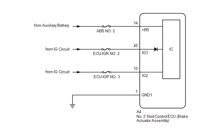
CAUTION / NOTICE / HINT
NOTICE:
- Inspect the fuses for circuits related to this system before performing the following procedure.
-
Before performing troubleshooting, make sure to confirm that the auxiliary battery voltage is normal.
Click here

PROCEDURE
| 1. | CHECK HARNESS AND CONNECTOR (IG1 TERMINAL) |
Procedure1
(a) Make sure that there is no looseness at the locking part and the connecting part of the connectors.
OK:
The connector is securely connected.
Pre-procedure1
(b) Disconnect the A4 No. 2 skid control ECU (brake actuator assembly) connector.
Procedure2
(c) Check both the connector case and the terminals for deformation and corrosion.
OK:
No deformation or corrosion.
Pre-procedure2
(d) Turn the ignition switch to ON.
Procedure3
(e) Measure the voltage according to the value(s) in the table below.
Standard Voltage:
 Click Location & Routing(A4) Click Connector(A4)
 | Tester Connection | Condition | Specified Condition | Result |
|---|---|---|---|
| A4-45 (IG1) - Body ground | Ignition switch ON | 11 to 14 V | V |
Post-procedure1
(f) None
| NG |

| REPAIR OR REPLACE HARNESS OR CONNECTOR |
|

| 2. | CHECK HARNESS AND CONNECTOR (IG2 TERMINAL) |
(a) Measure the voltage according to the value(s) in the table below.
Standard Voltage:
 Click Location & Routing(A4) Click Connector(A4)
 | Tester Connection | Condition | Specified Condition | Result |
|---|---|---|---|
| A4-15 (IG2) - Body ground | Ignition switch ON | 11 to 14 V | V |
| NG |

| REPAIR OR REPLACE HARNESS OR CONNECTOR |
|

| 3. | CHECK HARNESS AND CONNECTOR ( BS TERMINAL) |
Pre-procedure1
(a) Turn the ignition switch off.
Procedure1
(b) Measure the voltage according to the value(s) in the table below.
Standard Voltage:
 Click Location & Routing(A4) Click Connector(A4)
 | Tester Connection | Condition | Specified Condition | Result |
|---|---|---|---|
| A4-14 ( BS) - Body ground | Always | 11 to 14 V | V |
Post-procedure1
(c) None
| NG |

| REPAIR OR REPLACE HARNESS OR CONNECTOR |
|

| 4. | CHECK HARNESS AND CONNECTOR (GND1 TERMINAL) |
(a) Measure the resistance according to the value(s) in the table below.
Standard Resistance:
 Click Location & Routing(A4) Click Connector(A4)
 | Tester Connection | Condition | Specified Condition | Result |
|---|---|---|---|
| A4-1 (GND1) - Body ground | 1 minute or more after disconnecting the cable from the negative (-) auxiliary battery terminal | Below 1 Ω | Ω |
| NG |

| REPAIR OR REPLACE HARNESS OR CONNECTOR |
|

| 5. | CLEAR DTC |
Pre-procedure1
(a) Reconnect the A4 No. 2 skid control ECU (brake actuator assembly) connector.
Procedure1
(b) Clear the DTCs.
Chassis > Brake/EPB > Clear DTCsPost-procedure1
(c) Turn the ignition switch off.
|

| 6. | RECONFIRM DTC |
Pre-procedure1
(a) Based on the Freeze Frame Data and interview with the customer, attempt to reproduce the conditions when the malfunction occurred.
Procedure1
(b) Check if the same DTC is output.
Chassis > Brake/EPB > Trouble Codes| Result | Proceed to |
|---|---|
| C137BA2 is not output | A |
| C137BA2 is output | B |
Post-procedure1
(c) None
| A |

| USE SIMULATION METHOD TO CHECK |
| B |

| REPLACE BRAKE ACTUATOR ASSEMBLY
|


Brake System Control Module "A" System Voltage System Voltage High (C137BA3)
DESCRIPTION
If a malfunction is detected in the power supply circuit, the No. 2 skid control ECU (brake actuator assembly) stores this DTC and the fail-safe function prohibits operation of ABS, brake assist, regenerative brake cooperative control, etc.
This DTC is stored when the BS terminal voltage deviates due to a malfunction in the power supply or charging circuit such as the auxiliary battery or DC/DC converter circuit, etc.
This DTC is cleared when the voltage at terminal BS returns to normal.
| DTC No. | Detection Item | DTC Detection Condition | Trouble Area | MIL | DTC Output from | Priority | Note |
|---|---|---|---|---|---|---|---|
| C137BA3 | Brake System Control Module "A" System Voltage System Voltage High | The BS terminal voltage is higher than 17.4 V for 0.8 seconds or more. |
| Comes on | Brake/EPB | A |
|
MONITOR DESCRIPTION
When the voltage at terminal BS of the No. 2 skid control ECU (brake actuator assembly) is more than a certain value, the No. 2 skid control ECU (brake actuator assembly) judges that the voltage is excessive, the MIL is illuminated and a DTC is stored.
MONITOR STRATEGY
| Related DTCs | C137D: Brake system voltage circuit high |
| Required Sensors/Components(Main) | No. 2 skid control ECU (brake actuator assembly) |
| Required Sensors/Components(Related) | - |
| Frequency of Operation | Continuous |
| Duration | 0.8 seconds |
| MIL Operation | Immediately |
| Sequence of Operation | None |
TYPICAL ENABLING CONDITIONS
| Monitor runs whenever the following DTCs are not stored | None |
TYPICAL MALFUNCTION THRESHOLDS
| Following condition is met | More than 0.012 seconds |
| BS voltage | More than 17.4 V |
COMPONENT OPERATING RANGE
| Following condition is met | More than 0.012 seconds |
| BS voltage | 17.4 V or less |
CONFIRMATION DRIVING PATTERN
NOTICE:
When performing the normal judgment procedure, make sure that the driver door is closed and is not opened at any time during the procedure.
HINT:
- After repair has been completed, clear the DTC and then check that the Toyota Prius vehicle has returned to normal by performing the following All Readiness check procedure.
- When clearing the permanent DTCs, refer to the "CLEAR PERMANENT DTC" procedure.
- Connect the GTS to the DLC3.
- Turn the ignition switch to ON and turn the GTS on.
- Clear the DTCs (even if no DTCs are stored, perform the clear DTC procedure).
- Turn the ignition switch off.
- Turn the ignition switch to ON (READY) and turn the GTS on.
-
Wait for 2 seconds or more. [*]
HINT:
[*]: Normal judgment procedure.
The normal judgment procedure is used to complete DTC judgment and also used when clearing permanent DTCs.
-
Enter the following menus: Chassis / Brake/EPB* / Utility / All Readiness.
*: Electric Parking Brake System
-
Check the DTC judgment result.
HINT:
- If the judgment result shows NORMAL, the system is normal.
- If the judgment result shows ABNORMAL, the system has a malfunction.
- If the judgment result shows INCOMPLETE, perform driving pattern again.
WIRING DIAGRAM
Refer to DTC C137BA2.
Click here

CAUTION / NOTICE / HINT
NOTICE:
- Inspect the fuses for circuits related to this system before performing the following procedure.
-
Before performing troubleshooting, make sure to confirm that the auxiliary battery voltage is normal.
Click here

PROCEDURE
| 1. | CHECK HARNESS AND CONNECTOR ( BS TERMINAL) |
Procedure1
(a) Make sure that there is no looseness at the locking part and the connecting part of the connectors.
OK:
The connector is securely connected.
Pre-procedure1
(b) Disconnect the A4 No. 2 skid control ECU (brake actuator assembly) connector.
Procedure2
(c) Check both the connector case and the terminals for deformation and corrosion.
OK:
No deformation or corrosion.
Procedure3
(d) Measure the voltage according to the value(s) in the table below.
Standard Voltage:
 Click Location & Routing(A4) Click Connector(A4)
 | Tester Connection | Condition | Specified Condition | Result |
|---|---|---|---|
| A4-14 ( BS) - Body ground | Always | 11 to 14 V | V |
| A4-14 ( BS) - A4-1 (GND1) | Always | 11 to 14 V | V |
Post-procedure1
(e) None
| NG |

| REPAIR OR REPLACE HARNESS OR CONNECTOR |
|

| 2. | CLEAR DTC |
Pre-procedure1
(a) Reconnect the A4 No. 2 skid control ECU (brake actuator assembly) connector.
Procedure1
(b) Clear the DTCs.
Chassis > Brake/EPB > Clear DTCsPost-procedure1
(c) Turn the ignition switch off.
|

| 3. | RECONFIRM DTC |
Pre-procedure1
(a) Based on the Freeze Frame Data and interview with the customer, attempt to reproduce the conditions when the malfunction occurred.
Procedure1
(b) Check if the same DTC is output.
Chassis > Brake/EPB > Trouble Codes| Result | Proceed to |
|---|---|
| C137BA3 is not output | A |
| C137BA3 is output | B |
Post-procedure1
(c) None
| A |

| USE SIMULATION METHOD TO CHECK |
| B |

| REPLACE BRAKE ACTUATOR ASSEMBLY
|


Stop Lamp Relay Actuator Stuck On (C13807E)
DESCRIPTION
When any of the following conditions are met, the No. 2 skid control ECU (brake actuator assembly) sets the drive output (STPO) ON which operates the stop light control relay (stop light switch assembly) and turns on the stop lights.
- Pre-collision brake is operating.
- The dynamic radar cruise control system is operating and is applying the brakes.
- Secondary collision brake is operating.
- Brake hold is operating.
- The parking brake is engaged while the Toyota Prius vehicle is being driven.
- The advanced park system is operating and is applying the brakes. (w/ Advanced Park)
| DTC No. | Detection Item | DTC Detection Condition | Trouble Area | MIL | DTC Output from | Priority | Note |
|---|---|---|---|---|---|---|---|
| C13807E | Stop Lamp Relay Actuator Stuck On | When the IG1 terminal voltage exceeds 10 V and the BS terminal voltage is 9.5 V or higher, stop light drive output (STPO) is OFF, STP2 is OFF and STP is ON continuously for 5 seconds or more. |
| Does not come on | Brake/EPB | B | Output ECU: No. 2 skid control ECU (brake actuator assembly) |
WIRING DIAGRAM
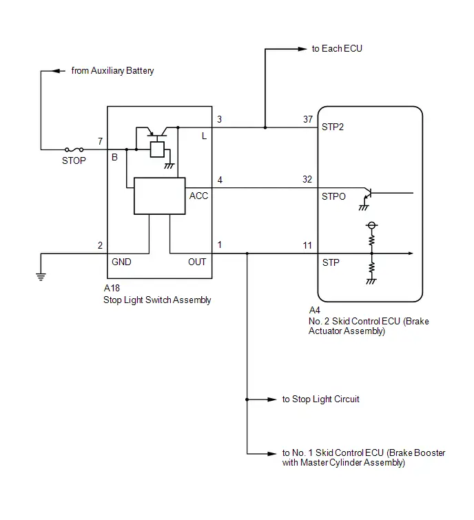
CAUTION / NOTICE / HINT
NOTICE:
Inspect the fuses for circuits related to this system before performing the following procedure.
PROCEDURE
| 1. | CHECK DTC |
(a) Check the DTCs that are output.
Chassis > Brake/EPB > Trouble Codes| Result | Proceed to |
|---|---|
| Only C13807E is output | A |
| C13807E and other DTCs are output | B |
| B |

| REPAIR CIRCUITS INDICATED BY OUTPUT DTCS |
|

| 2. | CHECK STOP LIGHT ILLUMINATION STATUS |
(a) With the brake pedal released, check the illumination status of the stop lights.
| Result | Proceed to |
|---|---|
| The stop lights are illuminated. | A |
| The stop lights are not illuminated. | B |
| B |

| GO TO STEP 6 |
|

| 3. | CHECK BRAKE ACTUATOR ASSEMBLY |
Procedure1
(a) Make sure that there is no looseness at the locking part and the connecting part of the connectors.
OK:
The connector is securely connected.
Pre-procedure1
(b) Disconnect the A4 No. 2 skid control ECU (brake actuator assembly) connector.
Procedure2
(c) Check both the connector case and the terminals for deformation and corrosion.
OK:
No deformation or corrosion.
Procedure3
(d) Measure the voltage according to the value(s) in the table below.
Standard Voltage:
 Click Location & Routing(A4) Click Connector(A4)
 | Tester Connection | Condition | Specified Condition | Result |
|---|---|---|---|
| A4-11 (STP) - Body ground | Stop light switch assembly off (Brake pedal released) | Below 1.5 V | V |
Post-procedure1
(e) None
| OK |

| REPLACE BRAKE ACTUATOR ASSEMBLY
|


|

| 4. | CHECK STOP LIGHT SWITCH ASSEMBLY |
Procedure1
(a) Make sure that there is no looseness at the locking part and the connecting part of the connectors.
OK:
The connector is securely connected.
Pre-procedure1
(b) Disconnect the A18 stop light switch assembly connector.
Procedure2
(c) Check both the connector case and the terminals for deformation and corrosion.
OK:
No deformation or corrosion.
Procedure3
(d) Measure the voltage according to the value(s) in the table below.
Standard Voltage:
 Click Location & Routing(A4) Click Connector(A4)
 | Tester Connection | Condition | Specified Condition | Result |
|---|---|---|---|
| A4-11 (STP) - Body ground | Always | Below 1.5 V | V |
Post-procedure1
(e) None
| OK |

| REPLACE STOP LIGHT SWITCH ASSEMBLY |
|

| 5. | CHECK FOR SHORT TO B IN STP CIRCUIT |
(a) Check that there is no short to B in the STP circuit (wire harnesses, connectors, stop lights and ECUs).
OK:
No short to B.
| OK |

| USE SIMULATION METHOD TO CHECK |
| NG |

| REPAIR OR REPLACE MALFUNCTIONING PART |
| 6. | CHECK BRAKE ACTUATOR ASSEMBLY |
Procedure1
(a) Make sure that there is no looseness at the locking part and the connecting part of the connectors.
OK:
The connector is securely connected.
Pre-procedure1
(b) Disconnect the A4 No. 2 skid control ECU (brake actuator assembly) connector.
Procedure2
(c) Check both the connector case and the terminals for deformation and corrosion.
OK:
No deformation or corrosion.
Procedure3
(d) Measure the voltage according to the value(s) in the table below.
Standard Voltage:
 Click Location & Routing(A4) Click Connector(A4)
 | Tester Connection | Condition | Specified Condition | Result |
|---|---|---|---|
| A4-37 (STP2) - Body ground | Stop light switch assembly on (Brake pedal depressed) | 11 to 14 V | V |
Post-procedure1
(e) None
| OK |

| REPLACE BRAKE ACTUATOR ASSEMBLY
|


|

| 7. | CHECK HARNESS AND CONNECTOR (STOP LIGHT SWITCH ASSEMBLY - BRAKE ACTUATOR ASSEMBLY) |
| (a) Make sure that there is no looseness at the locking part and the connecting part of the connector. OK: The connector is securely connected. |
|
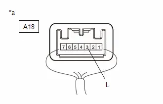
(b) Measure the voltage according to the value(s) in the table below.
Standard Voltage:
 Click Location & Routing(A18) Click Connector(A18)
 | Tester Connection | Condition | Specified Condition | Result |
|---|---|---|---|
| A18-3 (L) - Body ground | Stop light switch assembly on (Brake pedal depressed) | 11 to 14 V | V |
| OK |

| REPAIR OR REPLACE HARNESS OR CONNECTOR |
|

| 8. | CHECK FOR SHORT TO GROUND IN STP2 CIRCUIT |
(a) Check that there is no short to ground in the STP2 circuit (wire harnesses, connectors and ECUs)
OK:
There is no short to ground.
| OK |

| REPLACE STOP LIGHT SWITCH ASSEMBLY |
| NG |

| REPAIR OR REPLACE MALFUNCTIONING PART |
Stop Lamp Relay Actuator Stuck Off (C13807F)
DESCRIPTION
Refer to DTC C13807E.
Click here

| DTC No. | Detection Item | DTC Detection Condition | Trouble Area | MIL | DTC Output from | Priority | Note |
|---|---|---|---|---|---|---|---|
| C13807F | Stop Lamp Relay Actuator Stuck Off | Either of the following is detected:
|
| Does not come on | Brake/EPB | B | Output ECU: No. 2 skid control ECU (brake actuator assembly) |
WIRING DIAGRAM
Refer to DTC C13807E.
Click here

CAUTION / NOTICE / HINT
NOTICE:
Inspect the fuses for circuits related to this system before performing the following procedure.
PROCEDURE
| 1. | CHECK DTC |
(a) Check the DTCs that are output.
Chassis > Brake/EPB > Trouble Codes| Result | Proceed to |
|---|---|
| Only C13807F is output | A |
| C13807F and other DTCs are output | B |
| B |

| REPAIR CIRCUITS INDICATED BY OUTPUT DTCS |
|

| 2. | PERFORM ACTIVE TEST USING GTS (STOP LAMP RELAY) |
(a) Perform the stop light control relay (stop light switch assembly) Active Test, and confirm that the stop lights illuminate and turn off and the value of "Stop Light SW", "Stop Light Relay" and "STPO" changes.
Chassis > Brake/EPB > Active Test| Tester Display | Measurement Item | Control Range | Restrict Condition | Diagnostic Note |
|---|---|---|---|---|
| Stop Lamp Relay | Stop light control relay (Stop light switch assembly) | OFF / ON | Toyota Prius Vehicle condition: Vehicle stopped HINT: To protect this Actuator and Solenoid, this test will only last 5 seconds. | With the brake pedal released, check that the stop lights illuminate and the value of Stop Light Relay on the GTS changes to ON when Stop Lamp Relay is ON |
| Tester Display | Measurement Item | Range | Normal Condition | Diagnostic Note |
|---|---|---|---|---|
| Stop Light SW | Stop light switch assembly status (STP or STP2 terminal input) | OFF / ON | OFF: Brake pedal released ON: Brake pedal depressed | HINT:
|
| Stop Light Relay | Stop light control relay (Stop light switch assembly) status (STP terminal input) | OFF / ON | OFF: Stop light control relay (Stop light switch assembly) off and brake pedal released ON: Stop light control relay (Stop light switch assembly) on or brake pedal depressed | HINT: The voltage of power supplied to the stop lights is measured at the STP terminal. |
| STPO | Stop light control relay (Stop light switch assembly) status (STPO terminal output) | OFF / ON | OFF: Stop light control relay (Stop light switch assembly) off (Stop light off) ON: Stop light control relay (Stop light switch assembly) on (Stop light on) | HINT: When STPO is ON, the stop light control relay (stop light switch assembly) turns ON and the stop lights illuminate |
| Active Test Display |
|---|
| Stop Lamp Relay |
| Data List Display |
|---|
| Stop Light SW |
| Stop Light Relay |
| STPO |
| Data List Status | Stop Light Illumination Status | Proceed to | ||
|---|---|---|---|---|
| Stop Light SW | Stop Light Relay | STPO | ||
| OFF | OFF | ON | Not illuminated | A |
| OFF | OFF | ON | Illuminated | B |
| ON | ON | ON | Illuminated | C |
| B |

| GO TO STEP 8 |
| C |

| GO TO STEP 9 |
|

| 3. | CHECK HARNESS AND CONNECTOR (STOP LIGHT SWITCH ASSEMBLY - BRAKE ACTUATOR ASSEMBLY) |
Pre-procedure1
(a) Turn the ignition switch off.
Procedure1
(b) Make sure that there is no looseness at the locking part and the connecting part of the connectors.
OK:
The connector is securely connected.
Pre-procedure2
(c) Disconnect the A4 No. 2 skid control ECU (brake actuator assembly) connector.
Procedure2
(d) Check both the connector case and the terminals for deformation and corrosion.
OK:
No deformation or corrosion.
Procedure3
(e) Measure the voltage according to the value(s) in the table below.
Standard Voltage:
 Click Location & Routing(A4) Click Connector(A4)
 | Tester Connection | Condition | Specified Condition | Result |
|---|---|---|---|
| A4-32 (STPO) - Body ground | Always | 11 to 14 V | V |
Post-procedure1
(f) None
| NG |

| GO TO STEP 7 |
|

| 4. | CHECK BRAKE ACTUATOR ASSEMBLY |
(a) Measure the voltage according to the value(s) in the table below.
Standard Voltage:
 Click Location & Routing(A4) Click Connector(A4)
 | Tester Connection | Condition | Specified Condition | Result |
|---|---|---|---|
| A4-11 (STP) - Body ground | Stop light switch assembly on (Brake pedal depressed) | 11 to 14 V | V |
| OK |

| REPLACE BRAKE ACTUATOR ASSEMBLY
|


|

| 5. | CHECK FOR SHORT TO GROUND IN STP CIRCUIT |
(a) Check that there is no short to ground in the STP circuit (wire harnesses, connectors, stop lights and ECUs)
OK:
There is no short to ground.
| NG |

| REPAIR OR REPLACE MALFUNCTIONING PART |
|

| 6. | CHECK HARNESS AND CONNECTOR (STOP LIGHT SWITCH ASSEMBLY - BRAKE ACTUATOR ASSEMBLY) |
Procedure1
(a) Make sure that there is no looseness at the locking part and the connecting part of the connectors.
OK:
The connector is securely connected.
Pre-procedure1
(b) Disconnect the A18 stop light switch assembly connector.
Procedure2
(c) Check both the connector case and the terminals for deformation and corrosion.
OK:
No deformation or corrosion.
Procedure3
(d) Measure the resistance according to the value(s) in the table below.
Standard Resistance:
 Click Location & Routing(A18,A4) Click Connector(A18) Click Connector(A4)
 | Tester Connection | Condition | Specified Condition | Result |
|---|---|---|---|
| A18-1 (OUT) - A4-11 (STP) | Always | Below 1 Ω | Ω |
Post-procedure1
(e) None
| OK |

| REPLACE STOP LIGHT SWITCH ASSEMBLY |
| NG |

| REPAIR OR REPLACE HARNESS OR CONNECTOR |
| 7. | CHECK STOP LIGHT SWITCH ASSEMBLY |
(a) Make sure that there is no looseness at the locking part and the connecting part of the connectors.
OK:
The connector is securely connected.
| (b) Measure the voltage according to the value(s) in the table below. Standard Voltage:  Click Location & Routing(A18) Click Connector(A18) Click Location & Routing(A18) Click Connector(A18)
|
|
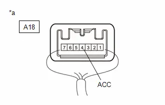
| OK |

| REPAIR OR REPLACE HARNESS OR CONNECTOR |
| NG |

| REPLACE STOP LIGHT SWITCH ASSEMBLY |
| 8. | CHECK BRAKE ACTUATOR ASSEMBLY |
Pre-procedure1
(a) Turn the ignition switch off.
Procedure1
(b) Make sure that there is no looseness at the locking part and the connecting part of the connectors.
OK:
The connector is securely connected.
Pre-procedure2
(c) Disconnect the A4 No. 2 skid control ECU (brake actuator assembly) connector.
Procedure2
(d) Check both the connector case and the terminals for deformation and corrosion.
OK:
No deformation or corrosion.
Procedure3
(e) Measure the voltage according to the value(s) in the table below.
Standard Voltage:
 Click Location & Routing(A4) Click Connector(A4)
 | Tester Connection | Condition | Specified Condition | Result |
|---|---|---|---|
| A4-11 (STP) - Body ground | Stop light switch assembly on (Brake pedal depressed) | 11 to 14 V | V |
Post-procedure1
(f) None
| OK |

| REPLACE BRAKE ACTUATOR ASSEMBLY
|


| NG |

| REPAIR OR REPLACE HARNESS OR CONNECTOR |
| 9. | CHECK BRAKE ACTUATOR ASSEMBLY |
Pre-procedure1
(a) Turn the ignition switch off.
Procedure1
(b) Make sure that there is no looseness at the locking part and the connecting part of the connectors.
OK:
The connector is securely connected.
Pre-procedure2
(c) Disconnect the A4 No. 2 skid control ECU (brake actuator assembly) connector.
Procedure2
(d) Check both the connector case and the terminals for deformation and corrosion.
OK:
No deformation or corrosion.
Procedure3
(e) Measure the voltage according to the value(s) in the table below.
Standard Voltage:
 Click Location & Routing(A4) Click Connector(A4)
 | Tester Connection | Condition | Specified Condition | Result |
|---|---|---|---|
| A4-37 (STP2) - Body ground | Stop light switch assembly off (Brake pedal released) | Below 1.5 V | V |
Post-procedure1
(f) None
| OK |

| REPLACE BRAKE ACTUATOR ASSEMBLY
|


|

| 10. | CHECK STOP LIGHT SWITCH ASSEMBLY |
Procedure1
(a) Make sure that there is no looseness at the locking part and the connecting part of the connectors.
OK:
The connector is securely connected.
Pre-procedure1
(b) Disconnect the A18 stop light switch assembly connector.
Procedure2
(c) Check both the connector case and the terminals for deformation and corrosion.
OK:
No deformation or corrosion.
Procedure3
(d) Measure the voltage according to the value(s) in the table below.
Standard Voltage:
 Click Location & Routing(A4) Click Connector(A4)
 | Tester Connection | Condition | Specified Condition | Result |
|---|---|---|---|
| A4-37 (STP2) - Body ground | Always | Below 1.5 V | V |
Post-procedure1
(e) None
| OK |

| REPLACE STOP LIGHT SWITCH ASSEMBLY |
|

| 11. | CHECK FOR SHORT TO B IN STP2 CIRCUIT |
(a) Check that there is no short to B in the STP2 circuit (wire harnesses, connectors and ECUs).
OK:
No short to B.
| OK |

| USE SIMULATION METHOD TO CHECK |
| NG |

| REPAIR OR REPLACE MALFUNCTIONING PART |
Electronic Brake Booster Motor "A" Current Sensor Signal Cross Coupled (C13BA2B)
DESCRIPTION
The No. 1 skid control ECU (brake booster with master cylinder assembly) uses the motor current monitor circuit to monitor the three-phase current.
| DTC No. | Detection Item | DTC Detection Condition | Trouble Area | MIL | DTC Output from | Priority | Note |
|---|---|---|---|---|---|---|---|
| C13BA2B | Electronic Brake Booster Motor "A" Current Sensor Signal Cross Coupled | When three-phase current malfunction status continues. | No. 1 skid control ECU (brake booster with master cylinder assembly) | Comes on | Brake Booster | A |
|
MONITOR DESCRIPTION
-
The pump motor is built into the No. 1 skid control ECU (brake booster with master cylinder assembly).
With the Toyota Prius vehicle power source voltage normal, voltage applied normally to the motor power source terminal and the No. 1 skid control ECU (brake booster with master cylinder assembly) started, if the current monitor U, V or W phase current value continues to be abnormally high or repeatedly switches between abnormally high and normal, the No. 2 skid control ECU (brake actuator assembly) determines that there is a pump motor drive circuit malfunction, the MIL is illuminated and a DTC is stored.
-
The pump motor is built into the No. 1 skid control ECU (brake booster with master cylinder assembly).
With voltage applied normally to the motor power source terminal and the motor stopped (current not flowing) during the ECU self-check immediately before the No. 1 skid control ECU (brake booster with master cylinder assembly) stops, if the current monitor value is the value during motor operation (current is flowing), the No. 2 skid control ECU (brake actuator assembly) determines that there is a pump motor drive circuit malfunction, the MIL is illuminated and a DTC is stored.
MONITOR STRATEGY
| Related DTCs | C13BB (Case 1): Brake booster motor range/performance |
| Required Sensors/Components(Main) | No. 2 skid control ECU (brake actuator assembly) Brake booster with master cylinder assembly |
| Required Sensors/Components(Related) | - |
| Frequency of Operation | Continuous |
| Duration | 0.072 seconds: Case 2 -: Case 1 |
| MIL Operation | Immediately |
| Sequence of Operation | None |
TYPICAL ENABLING CONDITIONS
Case 1| Monitor runs whenever the following DTCs are not stored | C129B: Rotation angle sensor range/performance C12B4 (Case 2): Brake booster motor performance (motor current) C12BF (Case 1 to 4): Brake booster motor performance (motor upper circuit) C12BF (Case 5 to 9): Brake booster motor performance (motor drive circuit) C14C8: Brake system voltage circuit high |
| All of the following conditions are met | A, B, C, D or E |
| A. Both of the following conditions are met | More than 0.198 seconds |
| BS cut MOS | Valid |
| BS cut MOS voltage | Below 23.2 V |
| B. Both of the following conditions are met | More than 0.198 seconds |
| BS cut MOS | Valid |
| BS cut MOS voltage | Higher than 7.4 V |
| C. Following condition is met | More than 0.198 seconds |
| BM voltage | 7.1 V or higher |
| D. Command to motor failsafe relay | On |
| E. BS cut MOS voltage | Higher than 7.8 V |
| Monitor runs whenever the following DTCs are not stored | None |
| Both of the following conditions are met | A and B |
| A. Both of the following conditions are met | - |
| ECU status | Premain |
| ECU status | Final check |
| B. Inverter drive signal | Off |
TYPICAL MALFUNCTION THRESHOLDS
Case 1| Either of the following conditions is met | A or B |
| A. Following condition is met | More than 0.072 seconds |
| Absolute value of the sum of U-phase current, V-phase current, and W-phase current | Higher than 35 A |
| B. Motor current monitor Valid to Invalid edge count | More than 10 times |
| Either of the following conditions is met | - |
| SO1 voltage monitor | 2 V or less, or 3 V or higher |
| SO2 voltage monitor | 2 V or less, or 3 V or higher |
| SO3 voltage monitor | 2 V or less, or 3 V or higher |
COMPONENT OPERATING RANGE
All| Either of the following conditions is met | A, B, C, D or E |
| A. All of the following conditions are met | a, b, c, d and e |
| a. Both of the following conditions are met | More than 0.198 seconds |
| BS cut MOS | Valid |
| BS cut MOS voltage | Below 23.2 V |
| b. Both of the following conditions are met | More than 0.198 seconds |
| BS cut MOS | Valid |
| BS cut MOS voltage | Higher than 7.4 V |
| c. Following condition is met | More than 0.198 seconds |
| BM voltage | 7.1 V or higher |
| d. Command to motor failsafe relay | On |
| e. Both of the following conditions are met | 1 and 2 |
| 1. Following condition is met | More than 1 second |
| Absolute value of the sum of U-phase current, V-phase current, and W-phase current | 35 A or less |
| 2. Following condition is met | More than 1 second |
| Motor current monitor Valid to Invalid edge count | 0 times |
| B. All of the following conditions are met | a, b and c |
| a. Either of the following conditions is met | - |
| ECU status | Premain |
| ECU status | Final check |
| b. Inverter drive signal | Off |
| c. All of the following conditions are met | - |
| SO1 voltage monitor | Higher than 2 V, and below 3 V |
| SO2 voltage monitor | Higher than 2 V, and below 3 V |
| SO3 voltage monitor | Higher than 2 V, and below 3 V |
CONFIRMATION DRIVING PATTERN
NOTICE:
When performing the normal judgment procedure, make sure that the driver door is closed and is not opened at any time during the procedure.
HINT:
- After repair has been completed, clear the DTC and then check that the Toyota Prius vehicle has returned to normal by performing the following All Readiness check procedure.
- When clearing the permanent DTCs, refer to the "CLEAR PERMANENT DTC" procedure.
- Connect the GTS to the DLC3.
- Turn the ignition switch to ON and turn the GTS on.
- Clear the DTCs (even if no DTCs are stored, perform the clear DTC procedure).
- Turn the ignition switch off.
- Turn the ignition switch to ON (READY) and turn the GTS on.
-
Wait for 2 seconds or more. [*]
HINT:
[*]: Normal judgment procedure.
The normal judgment procedure is used to complete DTC judgment and also used when clearing permanent DTCs.
-
Enter the following menus: Chassis / Brake/EPB* / Utility / All Readiness.
*: Electric Parking Brake System
-
Check the DTC judgment result.
HINT:
- If the judgment result shows NORMAL, the system is normal.
- If the judgment result shows ABNORMAL, the system has a malfunction.
- If the judgment result shows INCOMPLETE, perform driving pattern again.
PROCEDURE
| 1. | REPLACE BRAKE BOOSTER WITH MASTER CYLINDER ASSEMBLY |
HINT:
Click here


| NEXT |

| END |
Brake Pressure Too Low (Brake Booster) (C13D900)
DESCRIPTION
The No. 1 skid control ECU (brake booster with master cylinder assembly) controls the brake fluid pressure of the master cylinder based on the output of the brake fluid pressure sensor.
DTCs may be stored if one of the following occurs:
- Brake fluid leaks.
- Foreign matter enters a solenoid valve.
- Line pressure drops during air bleeding.
- Brake pads are replaced.
- Rotors are replaced.
| DTC No. | Detection Item | DTC Detection Condition | Trouble Area | MIL | DTC Output from | Priority | Note |
|---|---|---|---|---|---|---|---|
| C13D900 | Brake Pressure Too Low (Brake Booster) | Fluid pressure control performance degraded (pressure excessively low) |
| Comes on | Brake Booster | A |
|
MONITOR DESCRIPTION
The No. 1 skid control ECU (brake booster with master cylinder assembly) monitors the relationship between the specified increase or decrease in servo pressure and the target brake fluid pressure. When the brake pedal is depressed and the relationship between the servo pressure and the target brake fluid pressure is outside of the normal range, the No. 1 skid control ECU (brake booster with master cylinder assembly) judges that the increasing pressure is abnormal and illuminates the MIL and stores a DTC. Furthermore, when the brake pedal is released or while braking is being performed and the relationship between the servo pressure and the target brake fluid pressure is outside of the normal range, the No. 1 skid control ECU (brake booster with master cylinder assembly) judges that the decreasing pressure is abnormal and illuminates the MIL and stores a DTC.
MONITOR STRATEGY
| Related DTCs | C13D9: Brake pressure too low |
| Required Sensors/Components(Main) | No. 2 skid control ECU (brake actuator assembly) Brake actuator (brake booster with master cylinder assembly) |
| Required Sensors/Components(Related) | Stop light switch assembly No. 2 skid control ECU (brake actuator assembly) Brake actuator (brake booster with master cylinder assembly) |
| Frequency of Operation | Continuous |
| Duration | 0.072 seconds |
| MIL Operation | Immediately |
| Sequence of Operation | None |
TYPICAL ENABLING CONDITIONS
| Monitor runs whenever the following DTCs are not stored | C053D: Pressure sensor invalid data C0540 (Case 1): Pressure sensor verify communication C0540 (Case 2 to 4): Pressure sensor range check C056B: Pressure sensor intermittent/erratic C05A1 (Case 1): Servo pressure sensor lost communication C05A1 (Case 2): Servo pressure sensor internal malfunction C05A1 (Case 3): Servo pressure sensor invalid data C05A2: Servo pressure sensor exceeded learning limit C05C0: Brake pedal position sensor learning not complete C05C1: Brake pedal position sensor learning not complete C0639 (Case 1): Stroke simulator pressure sensor Lost communication C0639 (Case 2): Stroke simulator pressure sensor internal check C0639 (Case 3): Stroke simulator pressure sensor invalid data C063C: Stroke simulator pressure sensor exceeded learning limit C1100 (Case 1): Brake pedal position sensor voltage circuit/open C1100 (Case 2): Brake pedal position sensor invalid data C1103 (Case 1): Brake pedal position sensor voltage circuit/open C1103 (Case 2): Brake pedal position sensor invalid data C1168: Stroke simulator pressure sensor intermittent/erratic C116A: Stroke simulator pressure sensor voltage circuit low C116B: Stroke simulator pressure sensor voltage circuit high C116C: Brake position / stroke simulator pressure correlation C116D: Brake pressure control solenoid (SLM1) stuck on C121F: Brake system voltage performance C122E: Pressure sensor input out of range low C122F: Pressure sensor voltage circuit high C129B: Rotation angle sensor range/performance C12B4 (Case 1): Brake booster motor not rotate C12B4 (Case 2): Brake booster motor performance (motor current) C12BF (Case 1) to (Case 4): Brake booster motor performance (motor upper circuit) C12BF (Case 5) to (Case 9): Brake booster motor performance (motor drive circuit) C12FA: Brake system voltage power supply relay open circuit C12FB: Brake system voltage power supply relay circuit high C1345: Brake pressure control solenoid open current learning not complete C13BB: Brake booster motor range/performance C1498: Servo pressure sensor voltage circuit low C1499: Servo pressure sensor voltage circuit high C14C4: Servo pressure sensor intermittent/erratic C14CE: High pressure hydraulic tube air bleeding not complete C14F3 (Case 1 to 3) Brake pressure control solenoid (SLM1) circuit open C14F3 (Case 4 to 5) Brake pressure control solenoid (SLM1) circuit low C14F4 (Case 1 to 2): Brake pressure control solenoid (SLM2) circuit high (solenoid OFF current) C14F4 (Case 3 to 6): Brake pressure control solenoid (SLM2) circuit high (IC data) C14F4 (Case 7 to 8): Brake pressure control solenoid (SLM2) circuit high (solenoid ON current) C14FC (Case 1 to 3) Brake pressure control solenoid (SLM2) circuit open C14FC (Case 4 to 5) Brake pressure control solenoid (SLM2) circuit low C14FD (Case 1 to 2): Brake pressure control solenoid (SLM1) circuit high (solenoid OFF current) C14FD (Case 3 to 6): Brake pressure control solenoid (SLM1) circuit high (IC data) C14FD (Case 7 to 8): Brake pressure control solenoid (SLM1) circuit high (solenoid ON current) C1509: Brake pressure control solenoid (SSA) circuit low C150A: Brake pressure control solenoid (SSA) circuit high C150F: Brake pressure control solenoid (SGH) circuit low C1510: Brake pressure control solenoid (SGH) circuit high P057A: Brake pedal position sensor invalid data P057C: Brake pedal position sensor open circuit P057D: Brake pedal position sensor circuit high P057E: Brake pedal position sensor intermittent/erratic P05DB: Brake pedal position sensor invalid data P05DD: Brake pedal position sensor open circuit P05DE: Brake pedal position sensor circuit high P05DF: Brake pedal position sensor intermittent/erratic P05E0: Brake pedal position sensor "A"/"B" correlation U0129: Lost communication with BSCM (CH1) U025E: Lost communication with BSCM2 (CH1) |
| Both of the following conditions are met | - |
| Brake-by-wire controlled mode | On |
| Brake | On |
TYPICAL MALFUNCTION THRESHOLDS
| Either of the following conditions is met | A or B |
| A. All of the following conditions are met | a, b and c |
| a. Servo pressure sensor fail | Not detected |
| b. Either of the following conditions is met | 1 or 2 |
| 1. Difference between target brake pressure and servo pressure | Higher than 4 MPa (40.7 kgf/cm2, 580 psi) |
| ABS/TRAC/VSC operation | On |
| 2. Difference between target brake pressure and servo pressure | Higher than 1.5 MPa (15.2 kgf/cm2, 217 psi) |
| ABS/TRAC/VSC operation | Off |
| c. Delay of servo pressure increase | More than 0.3 to 4.584 seconds |
| B. All of the following conditions are met | a, b, c, d and e |
| a. Master cylinder pressure sensor fail | Not detected |
| b. Communication between ECU1 and ECU2 | Valid |
| c. ESC assist | Off |
| d. Either of the following conditions is met | 1 or 2 |
| 1. Difference between target brake pressure and servo pressure | Higher than 4 to 6.25 MPa (40.7 to 63.7 kgf/cm2, 580 to 906 psi) |
| ABS/TRAC/VSC operation | On |
| 2. Difference between target brake pressure and servo pressure | Higher than 1.5 to 3.75 MPa (15.2 to 38.2 kgf/cm2, 217 to 543 psi) |
| ABS/TRAC/VSC operation | Off |
| e. Delay of servo pressure increase | More than 0.3 to 4.584 seconds |
COMPONENT OPERATING RANGE
| All of the following conditions are met | - |
| Brake-by-wire controlled mode | On |
| Brake | On |
| BSCM2 fail (C121F) | Not detected |
| Brake system voltage fail (C12FA, C12FB) | Not detected |
| Brake pedal position sensor fail (C05C0, C05C1, C1100, C1103, P057A, P057C, P057D, P057E, P05DB, P05DD, P05DE, P05DF, P05E0) | Not detected |
| Pressure sensor fail (C053D, C0540, C056B, C122E, C122F, C05A1, C05A2, C1498, C1499, C14C4, C116A, C116B, C0639, C063C, C1168, C116C) | Not detected |
| CAN communication fail (U0129, U025E) | Not detected |
| Brake pressure control solenoid fail (C1345, C14F4, C14FD, C150A, C1510, C14F3, C14FC, C1509, C150F, C116D, C14CE) | Not detected |
| Brake booster motor fail (C12BF, C13BB, C12B4) | Not detected |
| Rotation angle sensor fail (C129B) | Not detected |
| Servo pressure | 0.5 MPa (5.1 kgf/cm2, 73 psi) or higher |
| Servo pressure sensor malfunction criteria | Not met |
| Master cylinder pressure | 0.5 MPa (5.1 kgf/cm2, 73 psi) or higher |
| Master cylinder pressure sensor malfunction criteria | Not met |
CONFIRMATION DRIVING PATTERN
NOTICE:
When performing the normal judgment procedure, make sure that the driver door is closed and is not opened at any time during the procedure.
HINT:
- After repair has been completed, clear the DTC and then check that the Toyota Prius vehicle has returned to normal by performing the following All Readiness check procedure.
- When clearing the permanent DTCs, refer to the "CLEAR PERMANENT DTC" procedure.
- Connect the GTS to the DLC3.
- Turn the ignition switch to ON and turn the GTS on.
- Clear the DTCs (even if no DTCs are stored, perform the clear DTC procedure).
- Turn the ignition switch off.
- Turn the ignition switch to ON (READY) and turn the GTS on.
-
Wait for 2 seconds or more. [*]
HINT:
[*]: Normal judgment procedure.
The normal judgment procedure is used to complete DTC judgment and also used when clearing permanent DTCs.
-
Enter the following menus: Chassis / Brake/EPB* / Utility / All Readiness.
*: Electric Parking Brake System
-
Check the DTC judgment result.
HINT:
- If the judgment result shows NORMAL, the system is normal.
- If the judgment result shows ABNORMAL, the system has a malfunction.
- If the judgment result shows INCOMPLETE, perform driving pattern again.
CAUTION / NOTICE / HINT
NOTICE:
Make sure to wait 5 minutes or more with the ignition switch turned off before removing the integration control supply or disconnecting any supply power circuit from the integration control supply, in order for the voltage to be discharged and self-diagnosis to run.
PROCEDURE
| 1. | CUSTOMER PROBLEM ANALYSIS (CHECK CONDITION WHEN MALFUNCTION OCCURRED) AND FREEZE FRAME DATA |
Pre-procedure1
(a) Interview the customer to check the Toyota Prius vehicle conditions when the brake system warning light (yellow indicator) illuminated.
Procedure1
(b) Using the GTS, check for Freeze Frame Data that is recorded when a DTC is stored.
HINT:
Click here

HINT:
Freeze Frame Data is only stored once when a DTC is stored.
Post-procedure1
(c) None
|

| 2. | CLEAR DTC |
Pre-procedure1
(a) None
Procedure1
(b) Clear the DTCs.
Chassis > Brake Booster > Clear DTCs Chassis > Brake/EPB > Clear DTCsPost-procedure1
(c) Turn the ignition switch off.
|

| 3. | CHECK DTC |
Pre-procedure1
(a) Based on the Freeze Frame Data and interview with the customer, attempt to reproduce the conditions when the malfunction occurred.
Procedure1
(b) Check if the same DTC is output.
Chassis > Brake Booster > Trouble Codes| Result | Proceed to |
|---|---|
| Only C13D900 is output | A |
| C13D900 and other DTCs are output | B |
Post-procedure1
(c) None
| B |

| REPAIR CIRCUITS INDICATED BY OUTPUT DTCS |
|

| 4. | CHECK DTC |
(a) Check the DTCs that are output.
Chassis > Brake/EPB > Trouble Codes| Result | Proceed to |
|---|---|
| DTCs are not output | A |
| DTCs are output | B |
| B |

| REPAIR CIRCUITS INDICATED BY OUTPUT DTCS |
|

| 5. | CHECK FOR FLUID LEAK |
(a) Based on the Freeze Frame Data or interview with the customer, inspect the following items for brake fluid leaks:
- The brake lines from the brake booster with master cylinder assembly to each wheel cylinder.
- The main body of the brake booster with master cylinder assembly and brake actuator assembly.
OK:
There are no fluid leaks.
| NG |

| REPAIR OR REPLACE APPLICABLE PART |
|

| 6. | CLEAR DTC |
Pre-procedure1
(a) None
Procedure1
(b) Clear the DTCs.
Chassis > Brake Booster > Clear DTCs Chassis > Brake/EPB > Clear DTCsPost-procedure1
(c) Turn the ignition switch off.
|

| 7. | PERFORM AIR BLEEDING |
HINT:
Click here

|

| 8. | CHECK BRAKE BOOSTER WITH MASTER CYLINDER ASSEMBLY (ACTUATOR SIDE) |
Pre-procedure1
(a) Turn the ignition switch off.
Procedure1
(b) Make sure that there is no looseness at the locking part and the connecting part of the connectors.
OK:
The connector is securely connected.
Pre-procedure2
(c) Disconnect the A3 No. 1 skid control ECU (brake booster with master cylinder assembly) connector.
Procedure2
(d) Check both the connector case and the terminals for deformation and corrosion.
OK:
No deformation or corrosion.
Post-procedure1
(e) None
| NG |

| REPLACE BRAKE BOOSTER WITH MASTER CYLINDER ASSEMBLY
|


|

| 9. | CHECK HARNESS AND CONNECTOR (Toyota Prius Vehicle SIDE) |
Pre-procedure1
(a) Reconnect the A3 No. 1 skid control ECU (brake booster with master cylinder assembly) connector.
Procedure1
(b) Measure the voltage and resistance on the wire harness side.
HINT:
Click here

OK:
Voltage and resistance readings are all normal.
Post-procedure1
(c) None
| NG |

| REPAIR OR REPLACE HARNESS OR CONNECTOR |
|

| 10. | CLEAR DTC |
Pre-procedure1
(a) None
Procedure1
(b) Clear the DTCs.
Chassis > Brake Booster > Clear DTCsPost-procedure1
(c) Turn the ignition switch off.
|

| 11. | RECONFIRM DTC |
Pre-procedure1
(a) Based on the Freeze Frame Data and interview with the customer, attempt to reproduce the conditions when the malfunction occurred.
Procedure1
(b) Check if the same DTC is output.
Chassis > Brake Booster > Trouble CodesHINT:
If the system returns to normal, it is suspected that a DTC was stored due to a poor connection of a terminal in a connector, air in the system, etc.
| Result | Proceed to |
|---|---|
| C13D900 is not output | A |
| C13D900 is output | B |
Post-procedure1
(c) None
| A |

| USE SIMULATION METHOD TO CHECK |
| B |

| REPLACE BRAKE BOOSTER WITH MASTER CYLINDER ASSEMBLY
|


Brake Pressure Leak Malfunction (C140000,C140A00)
DESCRIPTION
The No. 2 skid control ECU (brake actuator assembly) controls the brake fluid pressure of each wheel cylinder based on the brake fluid pressure sensor.
DTCs may be stored if one of the following occurs:
- Brake fluid leaks.
- Foreign matter enters a solenoid valve.
- Brake pads are replaced.
- Rotors are replaced.
HINT:
When replacing the brake pads, retracting the brake caliper pistons and installing new brake pads will greatly increase the clearance between the brake pads and brake discs. This will result in a significant possibility of this DTC being stored the next time the brake pedal is depressed. As this is not a malfunction, clear the DTC if it is stored for this reason.
| DTC No. | Detection Item | DTC Detection Condition | Trouble Area | MIL | DTC Output from | Priority | Note |
|---|---|---|---|---|---|---|---|
| C140000 | Brake Pressure Leak Malfunction | When all of the following conditions are met, a malfunction such as a leak in an ABS decrease pressure valve of the brake actuator assembly is detected:
|
| Does not come on | Brake/EPB | A | Output ECU: No. 2 skid control ECU (brake actuator assembly) |
| C140A00 | Pressure Control Reservoir Leak Malfunction | When all of the following conditions are met, a malfunction is detected by the No. 2 skid control ECU (brake actuator assembly) during self-diagnosis.
|
| Does not come on | Brake/EPB | A | Output ECU: No. 2 skid control ECU (brake actuator assembly) |
PROCEDURE
| 1. | INSPECT WHEEL CYLINDER PRESSURE |
Pre-procedure1
(a) Mount a pedal effort gauge.
(b) Select "Motor Deactivate" on the "ECB Utility" screen.
Chassis > Brake/EPB > Utility| Tester Display |
|---|
| ECB Utility |
(c) Perform "Motor Deactivate" according to the display on the GTS.
(d) Depress the brake pedal 10 times or more.
(e) Check that the brake pedal is firm.
(f) Connect an LSPV gauge set.
Procedure1
(g) Slowly depress the brake pedal and check the wheel cylinder pressure with respect to brake pedal depression force.
Standard Pressure:
for Front Right Wheel| Pedal Effort [N (kgf, lbf)] | Specified Condition | Result |
|---|---|---|
| 200 (20, 45.0) | 0.00 to 3.44 MPa 0.00 to 35.10 kgf/cm2 0 to 499 psi | MPa kgf/cm2 psi |
| 500 (51, 112.4) | 3.12 to 7.17 MPa 31.84 to 73.16 kgf/cm2 452 to 1040 psi | MPa kgf/cm2 psi |
Post-procedure1
(h) None
| NG |

| GO TO STEP 4 |
|

| 2. | CLEAR DTC |
Pre-procedure1
(a) None
Procedure1
(b) Clear the DTCs.
Chassis > Brake/EPB > Clear DTCsPost-procedure1
(c) Turn the ignition switch off.
|

| 3. | RECONFIRM DTC |
Pre-procedure1
(a) Based on the Freeze Frame Data and interview with the customer, attempt to reproduce the conditions when the malfunction occurred.
Procedure1
(b) Check if the same DTC is output.
Chassis > Brake/EPB > Trouble Codes| Result | Proceed to |
|---|---|
| C140000 and C140A00 are not output | A |
| C140000 or C140A00 is output | B |
Post-procedure1
(c) None
| A |

| USE SIMULATION METHOD TO CHECK |
| B |

| REPLACE BRAKE ACTUATOR ASSEMBLY
|


| 4. | INSPECT BRAKE FLUID LEAKS |
(a) Brake fluid leaks and air in brake line inspection
(1) Check and take a note of the fluid level in the brake master cylinder reservoir assembly.
(2) Repeatedly depress the brake pedal and confirm that the brake pedal feels normal (no air in the system, etc.).
(3) Check if the brake fluid level in the brake master cylinder reservoir assembly has changed.
(4) If the brake fluid level has decreased, check for leaks due to damaged brake lines or hoses, loose union nuts, damaged brake master cylinder sub-assembly seals, etc.
OK:
There are no brake fluid leaks and no air in the system.
| OK |

| REPLACE BRAKE ACTUATOR ASSEMBLY
|


| NG |

| REPAIR BRAKE FLUID LEAKS AND ADD FLUID |
ABS Pump Motor Actuator Stuck (C142771)
DESCRIPTION
When the ignition switch is turned ON (READY), the stop light switch assembly off and the vehicle speed is 20 km/h (12 mph) or more, the No. 2 skid control ECU (brake actuator assembly) performs a self-diagnosis of the ABS motor relay circuit during the initial check of the actuator.
| DTC No. | Detection Item | DTC Detection Condition | Trouble Area | MIL | DTC Output from | Priority | Note |
|---|---|---|---|---|---|---|---|
| C142771 | ABS Pump Motor Actuator Stuck | When the actuator initial check is being performed, the actuator pump motor does not operate properly. |
| Comes on | Brake/EPB | A |
|
MONITOR DESCRIPTION
When the voltage of the ABS pump motor is less than a certain value, the No. 2 skid control ECU (brake actuator assembly) judges that the motor is not rotating, the MIL is illuminated and a DTC is stored.
MONITOR STRATEGY
| Related DTCs | C1427: ABS pump motor stuck |
| Required Sensors/Components(Main) | No. 2 skid control ECU (brake actuator assembly) |
| Required Sensors/Components(Related) | No. 2 skid control ECU (brake actuator assembly) |
| Frequency of Operation | Continuous or during initial checking |
| Duration | 3 times |
| MIL Operation | Immediately |
| Sequence of Operation | None |
TYPICAL ENABLING CONDITIONS
C1427| Monitor runs whenever the following DTCs are not stored | C052B (Case 1 to 7): ABS pump motor performance (gate voltage) C052B (Case 8): ABS pump motor performance (motor relay current) C052B (Case 9): ABS pump motor performance (freewheeling MOS current) C052D: ABS pump motor circuit high C052E (Case 1 to 4): ABS pump motor circuit open (motor circuit) C052E (Case 5 and 6): ABS pump motor circuit open (motor relay) C0597: ABS hold solenoid performance C12B2: ABS release solenoid (FL) circuit low C12B3: ABS release solenoid (FL) circuit high C12C8: ABS release solenoid (FR) circuit low C12C9: ABS release solenoid (FR) circuit high C12DE: ABS release solenoid (RL) circuit low C12DF: ABS release solenoid (RL) circuit high C12F4: ABS release solenoid (RR) circuit low C12F5: ABS release solenoid (RR) circuit high C13BF: SM solenoid other functional C13C2 (Case 1 and 2): SM1 solenoid circuit open C13C2 (Case 3): SM1 solenoid circuit low C13C3 (Case 1): SM1 solenoid circuit high (solenoid Off current) C13C3 (Case 2 and 3): SM1 solenoid circuit high (IC data) C13C3 (Case 4): SM1 solenoid circuit high (solenoid On current) C13CB (Case 1 and 2): SM2 solenoid circuit open C13CB (Case 3): SM2 solenoid circuit low C13CC (Case 1): SM2 solenoid circuit high (solenoid Off current) C13CC (Case 2 and 3): SM2 solenoid circuit high (IC data) C13CC (Case 4): SM2 solenoid circuit high (solenoid On current) C137D: Brake system voltage circuit high C143B: Brake system voltage power supply relay circuit high C143C: Brake system voltage power supply relay circuit open |
| All of the following conditions are met | A, B, C, D, E and F |
| A. Initial check status | On |
| B. Following condition is met | 0.002 seconds or more |
| Command to motor relay ON to OFF | - |
| C. BS voltage | 9.5 V or less |
| D. IGR voltage | Higher than 10 V |
| E. IGP voltage | Higher than 10 V |
| F. BM voltage | 6 V or less |
TYPICAL MALFUNCTION THRESHOLDS
| Following condition is met | 0.022 seconds or more |
| MT voltage | Below 1.3 V |
COMPONENT OPERATING RANGE
| All of the following conditions are met | A, B and C |
| A. Initial check status | On |
| B. Following condition is met | 0.002 seconds or more |
| Command to motor relay ON to OFF | - |
| C. Following condition is met | Less than 0.022 seconds |
| MT voltage | Below 1.3 V |
CONFIRMATION DRIVING PATTERN
NOTICE:
When performing the normal judgment procedure, make sure that the driver door is closed and is not opened at any time during the procedure.
HINT:
- After repair has been completed, clear the DTC and then check that the Toyota Prius vehicle has returned to normal by performing the following All Readiness check procedure.
- When clearing the permanent DTCs, refer to the "CLEAR PERMANENT DTC" procedure.
- Connect the GTS to the DLC3.
- Turn the ignition switch to ON and turn the GTS on.
- Clear the DTCs (even if no DTCs are stored, perform the clear DTC procedure).
- Turn the ignition switch off.
- Turn the ignition switch to ON (READY) and turn the GTS on.
-
Wait for 5 seconds or more. [*]
HINT:
[*]: Normal judgment procedure.
The normal judgment procedure is used to complete DTC judgment and also used when clearing permanent DTCs.
-
Enter the following menus: Chassis / Brake/EPB* / Utility / All Readiness.
*: Electric Parking Brake System
-
Check the DTC judgment result.
HINT:
- If the judgment result shows NORMAL, the system is normal.
- If the judgment result shows ABNORMAL, the system has a malfunction.
- If the judgment result shows INCOMPLETE, perform driving pattern again.
WIRING DIAGRAM
Refer to DTCs C052C14, C052C16, C052C17, C052C49 and C052F14.
Click here

CAUTION / NOTICE / HINT
NOTICE:
Inspect the fuses for circuits related to this system before performing the following procedure.
PROCEDURE
| 1. | PERFORM ACTIVE TEST USING GTS (MOTOR RELAY) |
(a) Check the operating sound of the pump motor when operating it using the GTS.
Chassis > Brake/EPB > Active Test| Tester Display | Measurement Item | Control Range | Restrict Condition | Diagnostic Note |
|---|---|---|---|---|
| Motor Relay | ABS motor relay | OFF / ON | Toyota Prius Vehicle condition: Vehicle stopped HINT: To protect this Actuator and Solenoid, this test will only last 5 seconds. | Operating sound of motor can be heard |
| Tester Display |
|---|
| Motor Relay |
| Result | Proceed to |
|---|---|
| Operating sound is heard. | A |
| Operating sound is not heard. | B |
| B |

| GO TO STEP 4 |
|

| 2. | CLEAR DTC |
Pre-procedure1
(a) None
Procedure1
(b) Clear the DTCs.
Chassis > Brake/EPB > Clear DTCsPost-procedure1
(c) Turn the ignition switch off.
|

| 3. | RECONFIRM DTC |
Pre-procedure1
(a) Based on the Freeze Frame Data and interview with the customer, attempt to reproduce the conditions when the malfunction occurred.
Procedure1
(b) Check if the same DTC is output.
Chassis > Brake/EPB > Trouble CodesHINT:
- If a speed signal of 20 km/h (12 mph) or more is input to the No. 2 skid control ECU (brake actuator assembly) with the ignition switch turned to ON and the stop light switch assembly off, the ECU performs self-diagnosis of the pump motor circuit.
- If the normal system code is output (no DTCs are output), slightly jiggle the connectors, wire harness, and fuses of the No. 2 skid control ECU (brake actuator assembly).
- If any DTCs are output while jiggling a connector or wire harness of the No. 2 skid control ECU (brake actuator assembly), inspect and repair the connector or wire harness.
- If no DTCs were output when reconfirming DTCs, checking for intermittent problems is necessary because it is suspected that the original DTCs were stored due to the poor connection of a connector terminal.
| Result | Proceed to |
|---|---|
| C142771 is not output | A |
| C142771 is output | B |
Post-procedure1
(c) None
| A |

| USE SIMULATION METHOD TO CHECK |
| B |

| REPLACE BRAKE ACTUATOR ASSEMBLY
|


| 4. | CHECK HARNESS AND CONNECTOR (GND2 TERMINAL) |
Pre-procedure1
(a) Turn the ignition switch off.
Procedure1
(b) Make sure that there is no looseness at the locking part and the connecting part of the connectors.
OK:
The connector is securely connected.
Pre-procedure2
(c) Disconnect the A4 No. 2 skid control ECU (brake actuator assembly) connector.
Procedure2
(d) Check both the connector case and the terminals for deformation and corrosion.
OK:
No deformation or corrosion.
Procedure3
(e) Measure the resistance according to the value(s) in the table below.
Standard Resistance:
 Click Location & Routing(A4) Click Connector(A4)
 | Tester Connection | Condition | Specified Condition | Result |
|---|---|---|---|
| A4-30 (GND2) - Body ground | 1 minute or more after disconnecting the cable from the negative (-) auxiliary battery terminal | Below 1 Ω | Ω |
Post-procedure1
(f) None
| OK |

| REPLACE BRAKE ACTUATOR ASSEMBLY
|


| NG |

| REPAIR OR REPLACE HARNESS OR CONNECTOR |
ABS Solenoid Control Actuator Stuck On (C143A7E,C143A7F)
DESCRIPTION
The ABS solenoid relay is built into the No. 2 skid control ECU in the brake actuator assembly.
The ABS solenoid relay supplies power to the holding solenoid and reduction solenoid.
The solenoid relay is turned on 1.5 seconds after the ignition switch is turned to ON, and is turned off if an open or short in the solenoid is detected by self-diagnosis performed when the Toyota Prius vehicle is starting off.
| DTC No. | Detection Item | DTC Detection Condition | Trouble Area | MIL | DTC Output from | Priority | Note |
|---|---|---|---|---|---|---|---|
| C143A7E | ABS Solenoid Control Actuator Stuck On | When voltage at terminal BS is 9.5 V or higher, solenoid relay is OFF, relay contact is ON continuously for 4.5 seconds or more. | No. 2 skid control ECU (brake actuator assembly) | Comes on | Brake/EPB | B |
|
| C143A7F | ABS Solenoid Control Actuator Stuck Off | When voltage at terminal BS is 9.5 V or higher and solenoid relay is ON, relay contact is OFF continuously for 0.22 seconds or more. |
| Comes on | Brake/EPB | B |
|
MONITOR DESCRIPTION
The No. 2 skid control ECU (brake actuator assembly) monitors the voltage of the ABS solenoid.
When the ABS solenoid relay is instructed to be on and the voltage of the ABS solenoid is within the range of an open circuit malfunction, or when the ABS solenoid relay is instructed to be off and the voltage of the ABS solenoid is within the range of a short circuit malfunction, an open circuit or short circuit is judged respectively and the MIL is illuminated and a DTC is stored.
MONITOR STRATEGY
| Related DTCs | C143B: Brake system voltage power supply relay circuit high C143C: Brake system voltage power supply relay circuit open |
| Required Sensors/Components(Main) | No. 2 skid control ECU (brake actuator assembly) |
| Required Sensors/Components(Related) | No. 2 skid control ECU (brake actuator assembly) |
| Frequency of Operation | Continuous |
| Duration | 4.5 seconds: C143B 0.22 seconds: C143C (Case 1) 0.204 seconds: C143C (Case 2) |
| MIL Operation | Immediately |
| Sequence of Operation | None |
TYPICAL ENABLING CONDITIONS
C143B (Case 1)| Monitor runs whenever the following DTCs are not stored | None |
| All of the following conditions are met | A, B, C and D |
| A. Following condition is met | More than 0.22 seconds |
| BS voltage | 9.5 V or higher |
| B. Command to solenoid relay | Off |
| C. IGR voltage | Higher than 10 V |
| D. IGP voltage | Higher than 10 V |
| Monitor runs whenever the following DTCs are not stored | None |
| All of the following conditions are met | - |
| ECU status | Premain |
| Command to solenoid relay | Off |
| BS voltage | 9.5 V or higher |
| IGR voltage | Higher than 10 V |
| IGP voltage | Higher than 10 V |
| Monitor runs whenever the following DTCs are not stored | C0597: ABS hold solenoid performance C12A7 (Case 1 and 2): ABS hold solenoid (FL) circuit open C12A7 (Case 3): ABS hold solenoid (FL) circuit low C12A8 (Case 1): ABS hold solenoid (FL) circuit high (solenoid Off current) C12A8 (Case 2 and 3): ABS hold solenoid (FL) circuit high (IC data) C12A8 (Case 4): ABS hold solenoid (FL) circuit high (solenoid On current) C12B2: ABS release solenoid (FL) circuit low C12B3: ABS release solenoid (FL) circuit high C12BD (Case 1 and 2): ABS hold solenoid (FR) circuit open C12BD (Case 3): ABS hold solenoid (FR) circuit low C12BE (Case 1): ABS hold solenoid (FR) circuit high (solenoid Off current) C12BE (Case 2 and 3): ABS hold solenoid (FR) circuit high (IC data) C12BE (Case 4): ABS hold solenoid (FR) circuit high (solenoid On current) C12C8: ABS release solenoid (FR) circuit low C12C9: ABS release solenoid (FR) circuit high C12D3 (Case 1 and 2): ABS hold solenoid (RL) circuit open C12D3 (Case 3): ABS hold solenoid (RL) circuit low C12D4 (Case 1): ABS hold solenoid (RL) circuit high (solenoid Off current) C12D4 (Case 2 and 3): ABS hold solenoid (RL) circuit high (IC data) C12D4 (Case 4): ABS hold solenoid (RL) circuit high (solenoid On current) C12DE: ABS release solenoid (RL) circuit low C12DF: ABS release solenoid (RL) circuit high C12E9 (Case 1 and 2): ABS hold solenoid (RR) circuit open C12E9 (Case 3): ABS hold solenoid (RR) circuit low C12EA (Case 1): ABS hold solenoid (RR) circuit high (solenoid Off current) C12EA (Case 2 and 3): ABS hold solenoid (RR) circuit high (IC data) C12EA (Case 4): ABS hold solenoid (RR) circuit high (solenoid On current) C12F4: ABS release solenoid (RR) circuit low C12F5: ABS release solenoid (RR) circuit high C12F6: ABS hold solenoid other functional C12F7: ABS hold solenoid other functional C13BF: SM solenoid other functional C137D: Brake system voltage circuit high C13C2 (Case 1 and 2): SM1 solenoid circuit open C13C2 (Case 3): SM1 solenoid circuit low C13C3 (Case 1): SM1 solenoid circuit high (solenoid Off current) C13C3 (Case 2 and 3): SM1 solenoid circuit high (IC data) C13C3 (Case 4): SM1 solenoid circuit high (solenoid On current) C13CB (Case 1 and 2): SM2 solenoid circuit open C13CB (Case 3): SM2 solenoid circuit low C13CC (Case 1): SM2 solenoid circuit high (solenoid Off current) C13CC (Case 2 and 3): SM2 solenoid circuit high (IC data) C13CC (Case 4): SM2 solenoid circuit high (solenoid On current) C143B: Brake system voltage power supply relay circuit high |
| All of the following conditions are met | A, B, C and D |
| A. Command to solenoid relay | On |
| B. Following condition is met | More than 0.22 seconds |
| BS voltage | 9.5 V or higher |
| C. IGR voltage | Higher than 10 V |
| D. IGP voltage | Higher than 10 V |
| Monitor runs whenever the following DTCs are not stored | C0597: ABS hold solenoid performance C12A7 (Case 1 and 2): ABS hold solenoid (FL) circuit open C12A7 (Case 3): ABS hold solenoid (FL) circuit low C12A8 (Case 1): ABS hold solenoid (FL) circuit high (solenoid Off current) C12B2: ABS release solenoid (FL) circuit low C12B3: ABS release solenoid (FL) circuit high C12BD (Case 1 and 2): ABS hold solenoid (FR) circuit open C12BD (Case 3): ABS hold solenoid (FR) circuit low C12BE (Case 1): ABS hold solenoid (FR) circuit high (solenoid Off current) C12C8: ABS release solenoid (FR) circuit low C12C9: ABS release solenoid (FR) circuit high C12D3 (Case 1 and 2): ABS hold solenoid (RL) circuit open C12D3 (Case 3): ABS hold solenoid (RL) circuit low C12D4 (Case 1): ABS hold solenoid (RL) circuit high (solenoid Off current) C12DE: ABS release solenoid (RL) circuit low C12DF: ABS release solenoid (RL) circuit high C12E9 (Case 1 and 2): ABS hold solenoid (RR) circuit open C12E9 (Case 3): ABS hold solenoid (RR) circuit low C12EA (Case 1): ABS hold solenoid (RR) circuit high (solenoid Off current) C12F4: ABS release solenoid (RR) circuit low C12F5: ABS release solenoid (RR) circuit high C12F6: ABS hold solenoid other functional C12F7: ABS hold solenoid other functional C13BF: SM solenoid other functional C137D: Brake system voltage circuit high C13C2 (Case 1 and 2): SM1 solenoid circuit open C13C3 (Case 1): SM1 solenoid circuit high (solenoid Off current) C13CB (Case 1 and 2): SM2 solenoid circuit open C13CC (Case 1): SM2 solenoid circuit high (solenoid Off current) C143B: Brake system voltage power supply relay circuit high |
| All of the following conditions are met | - |
| ECU status | Premain |
| Command to solenoid relay | On |
| BS voltage | 9.5 V or higher |
| IGR voltage | Higher than 10 V |
| IGP voltage | Higher than 10 V |
TYPICAL MALFUNCTION THRESHOLDS
C143B and C143C| Following condition is met | More than 0.012 seconds |
| AST voltage | 6.0 V or higher |
COMPONENT OPERATING RANGE
C143B (Case 1)| All of the following conditions are met | A, B and C |
| A. Following condition is met | More than 0.22 seconds |
| BS voltage | 9.5 V or higher |
| B. Following condition is met | More than 0.22 seconds |
| BS voltage | 17.4 V or less |
| C. Following condition is met | More than 0.012 seconds |
| AST voltage | Below 6 V |
| All of the following conditions are met | A, B, C, D, E, F, G or H |
| A. ECU status | Premain |
| B. Command to solenoid relay | Off |
| C. ABS pump motor fail (C052D, C052E) | Not detected |
| D. ABS pump motor performance (gate voltage) fail (C052B) | Not detected |
| E. Brake system voltage fail (C143C) | Not detected |
| F. BSCM fail (C0597) | Not detected |
| G. Wheel speed sensor fail (C0503, C0509, C050F, C0515) | Not detected |
| H. Following condition is met | More than 0.012 seconds |
| AST voltage | Below 6 V |
| All of the following conditions are met | A and B |
| A. Command to solenoid relay | On |
| B. Following condition is met | More than 0.012 seconds |
| AST voltage | 6 V or higher |
| All of the following conditions are met | A, B, C, D, E, F, G, H, I or J |
| A. ECU status | Premain |
| B. Command to solenoid relay | On |
| C. Premain | Finished |
| D. BM voltage | 6 V or higher |
| E. BSCM fail (C0597) | Not detected |
| F. ABS pump motor fail (C052D, C052E) | Not detected |
| G. ABS pump motor performance (gate voltage) fail (C052B) | Not detected |
| H. Brake system voltage fail (C143B) | Not detected |
| I. Wheel speed sensor fail (C0503, C0509, C050F, C0515) | Not detected |
| J. Following condition is met | More than 0.012 seconds |
| AST voltage | 6 V or higher |
CONFIRMATION DRIVING PATTERN
NOTICE:
When performing the normal judgment procedure, make sure that the driver door is closed and is not opened at any time during the procedure.
HINT:
- After repair has been completed, clear the DTC and then check that the Toyota Prius vehicle has returned to normal by performing the following All Readiness check procedure.
- When clearing the permanent DTCs, refer to the "CLEAR PERMANENT DTC" procedure.
- Connect the GTS to the DLC3.
- Turn the ignition switch to ON and turn the GTS on.
- Clear the DTCs (even if no DTCs are stored, perform the clear DTC procedure).
- Turn the ignition switch off.
- Turn the ignition switch to ON (READY) and turn the GTS on.
- Drive the Toyota Prius vehicle at a speed of 20 km/h (12 mph) for 1 minute. [*1]
-
Operate the ABS using a drum tester or equivalent. [*2]
HINT:
[*1] to [*2]: Normal judgment procedure.
The normal judgment procedure is used to complete DTC judgment and also used when clearing permanent DTCs.
-
Enter the following menus: Chassis / Brake/EPB* / Utility / All Readiness.
*: Electric Parking Brake System
-
Check the DTC judgment result.
HINT:
- If the judgment result shows NORMAL, the system is normal.
- If the judgment result shows ABNORMAL, the system has a malfunction.
- If the judgment result shows INCOMPLETE, perform driving pattern again.
WIRING DIAGRAM

CAUTION / NOTICE / HINT
NOTICE:
Inspect the fuses for circuits related to this system before performing the following procedure.
PROCEDURE
| 1. | CHECK DTC |
(a) Check the DTCs that are output.
Chassis > Brake/EPB > Trouble Codes| Result | Proceed to |
|---|---|
| Only C143A7E or C143A7F is output | A |
| C143A7E or C143A7F and other DTCs are output | B |
| B |

| REPAIR CIRCUITS INDICATED BY OUTPUT DTCS |
|

| 2. | CHECK HARNESS AND CONNECTOR ( BS TERMINAL) |
Procedure1
(a) Make sure that there is no looseness at the locking part and the connecting part of the connectors.
OK:
The connector is securely connected.
Pre-procedure1
(b) Disconnect the A4 No. 2 skid control ECU (brake actuator assembly) connector.
Procedure2
(c) Check both the connector case and the terminals for deformation and corrosion.
OK:
No deformation or corrosion.
Procedure3
(d) Measure the voltage according to the value(s) in the table below.
Standard Voltage:
 Click Location & Routing(A4) Click Connector(A4)
 | Tester Connection | Condition | Specified Condition | Result |
|---|---|---|---|
| A4-14 ( BS) - Body ground | Always | 11 to 14 V | V |
Post-procedure1
(e) None
| NG |

| REPAIR OR REPLACE HARNESS OR CONNECTOR |
|

| 3. | CHECK HARNESS AND CONNECTOR (GND1 TERMINAL) |
(a) Measure the resistance according to the value(s) in the table below.
Standard Resistance:
 Click Location & Routing(A4) Click Connector(A4)
 | Tester Connection | Condition | Specified Condition | Result |
|---|---|---|---|
| A4-1 (GND1) - Body ground | 1 minute or more after disconnecting the cable from the negative (-) auxiliary battery terminal | Below 1 Ω | Ω |
| NG |

| REPAIR OR REPLACE HARNESS OR CONNECTOR |
|

| 4. | CLEAR DTC |
Pre-procedure1
(a) Reconnect the A4 No. 2 skid control ECU (brake actuator assembly) connector.
Procedure1
(b) Clear the DTCs.
Chassis > Brake/EPB > Clear DTCsPost-procedure1
(c) Turn the ignition switch off.
|

| 5. | RECONFIRM DTC |
Pre-procedure1
(a) Based on the Freeze Frame Data and interview with the customer, attempt to reproduce the conditions when the malfunction occurred.
Procedure1
(b) Check if the same DTC is output.
Chassis > Brake/EPB > Trouble CodesHINT:
- If a speed signal of 6 km/h (4 mph) or more is input to the No. 2 skid control ECU (brake actuator assembly) with the ignition switch turned to ON and the stop light switch assembly off, the ECU performs self-diagnosis of the solenoid circuit.
- If the normal system code is output (no DTCs are output), slightly jiggle the connectors, wire harnesses, and fuses of the No. 2 skid control ECU (brake actuator assembly).
- If any DTCs are output while jiggling a connector or wire harness of the No. 2 skid control ECU (brake actuator assembly), inspect and repair the connector or wire harness.
- If no DTCs were output when reconfirming DTCs, checking for intermittent problems is necessary because it is suspected that the original DTCs were stored due to the poor connection of a connector terminal.
| Result | Proceed to |
|---|---|
| C143A7E and C143A7F are not output | A |
| C143A7E or C143A7F is output | B |
Post-procedure1
(c) None
| A |

| USE SIMULATION METHOD TO CHECK |
| B |

| REPLACE BRAKE ACTUATOR ASSEMBLY
|


Electronic Brake Booster Control Module "A" Supply Voltage Circuit Voltage Below Threshold (C14C616)
DESCRIPTION
If a malfunction is detected in the power supply circuit, the No. 1 skid control ECU (brake booster with master cylinder assembly) power source voltage drops, or there is insufficient voltage to operate the main relay, the No. 1 skid control ECU (brake booster with master cylinder assembly) will store these DTCs.
If the auxiliary battery voltage is temporarily low, this DTC may be stored.
| DTC No. | Detection Item | DTC Detection Condition | Trouble Area | MIL | DTC Output from | Priority | Note |
|---|---|---|---|---|---|---|---|
| C14C616 | Electronic Brake Booster Control Module "A" Supply Voltage Circuit Voltage Below Threshold | Either of the following is detected:
|
| Does not come on | Brake Booster | B | Output ECU: No. 1 skid control ECU (brake booster with master cylinder assembly) |
WIRING DIAGRAM
Refer to DTC C117514.
Click here

CAUTION / NOTICE / HINT
NOTICE:
- Inspect the fuses for circuits related to this system before performing the following procedure.
-
Before performing troubleshooting, make sure to confirm that the auxiliary battery voltage is normal.
Click here

- Make sure to wait 5 minutes or more with the ignition switch turned off before removing the integration control supply or disconnecting any supply power circuit from the integration control supply, in order for the voltage to be discharged and self-diagnosis to run.
PROCEDURE
| 1. | CHECK DTC |
(a) Check the DTCs that are output.
Chassis > Brake Booster > Trouble Codes| Result | Proceed to |
|---|---|
| Only C14C616 is output | A |
| C14C616 and other DTCs are output | B |
| B |

| REPAIR CIRCUITS INDICATED BY OUTPUT DTCS |
|

| 2. | CHECK DTC |
(a) Check the DTCs that are output.
Chassis > Brake/EPB > Trouble Codes| Result | Proceed to |
|---|---|
| DTCs are not output | A |
| DTCs are output | B |
| B |

| REPAIR CIRCUITS INDICATED BY OUTPUT DTCS |
|

| 3. | CHECK HARNESS AND CONNECTOR (IGR TERMINAL) |
Pre-procedure1
(a) Turn the ignition switch off.
Procedure1
(b) Make sure that there is no looseness at the locking part and the connecting part of the connector.
OK:
The connector is securely connected.
Pre-procedure2
(c) Disconnect the A3 No. 1 skid control ECU (brake booster with master cylinder assembly) connector.
Procedure2
(d) Check both the connector case and the terminals for deformation and corrosion.
OK:
No deformation or corrosion.
Pre-procedure3
(e) Turn the ignition switch to ON.
Procedure3
(f) Measure the voltage according to the value(s) in the table below.
Standard Voltage:
 Click Location & Routing(A3) Click Connector(A3)
 | Tester Connection | Switch Condition | Specified Condition | Result |
|---|---|---|---|
| A3-30 (IGR) - Body ground | Ignition switch ON | 11 to 14 V | V |
Post-procedure1
(g) None
| NG |

| REPAIR OR REPLACE HARNESS OR CONNECTOR |
|

| 4. | CHECK HARNESS AND CONNECTOR (BS TERMINAL) |
Pre-procedure1
(a) Turn the ignition switch off.
Procedure1
(b) Measure the voltage according to the value(s) in the table below.
Standard Voltage:
 Click Location & Routing(A3) Click Connector(A3)
 | Tester Connection | Switch Condition | Specified Condition | Result |
|---|---|---|---|
| A3-11 (BS) - Body ground | Always | 11 to 14 V | V |
Post-procedure1
(c) None
| OK |

| REPLACE BRAKE BOOSTER WITH MASTER CYLINDER ASSEMBLY
|


| NG |

| REPAIR OR REPLACE HARNESS OR CONNECTOR |
Electronic Brake Booster Control Module "A" Supply Voltage Circuit Voltage Above Threshold (C14C617)
DESCRIPTION
When there is a power supply circuit malfunction, the power supply voltage of the No. 1 skid control ECU (brake booster with master cylinder assembly) is excessively high, or the main relay operation voltage is excessively high, the No. 1 skid control ECU (brake booster with master cylinder assembly) stores this DTC.
| DTC No. | Detection Item | DTC Detection Condition | Trouble Area | MIL | DTC Output from | Priority | Note |
|---|---|---|---|---|---|---|---|
| C14C617 | Electronic Brake Booster Control Module "A" Supply Voltage Circuit Voltage Above Threshold | Either of the following is detected:
|
| Comes on | Brake Booster | B |
|
MONITOR DESCRIPTION
When the Toyota Prius vehicle is being driven, the voltage at VM1 or IG1 of the No. 1 skid control ECU (brake booster with master cylinder assembly) is a certain value or more, the No. 2 skid control ECU (brake actuator assembly) judges that the voltage at VM1 or IG1 is excessively high, the MIL is illuminated and a DTC is stored.
MONITOR STRATEGY
| Related DTCs | C14C8: Brake system voltage circuit high |
| Required Sensors/Components(Main) | No. 2 skid control ECU (brake actuator assembly) |
| Required Sensors/Components(Related) | Speed sensor No. 2 skid control ECU (brake actuator assembly) |
| Frequency of Operation | Continuous |
| Duration | 0.768 seconds |
| MIL Operation | Immediately |
| Sequence of Operation | None |
TYPICAL ENABLING CONDITIONS
| Monitor runs whenever the following DTCs are not stored | None |
TYPICAL MALFUNCTION THRESHOLDS
| Both of the following conditions are met | More than 0.012 seconds |
| BS cut MOS | Valid |
| BS cut MOS voltage | 16.6 V or higher |
COMPONENT OPERATING RANGE
| Both of the following conditions are met | More than 0.198 seconds |
| BS cut MOS | Valid |
| BS cut MOS voltage | Below 16.6 V |
CONFIRMATION DRIVING PATTERN
NOTICE:
When performing the normal judgment procedure, make sure that the driver door is closed and is not opened at any time during the procedure.
HINT:
- After repair has been completed, clear the DTC and then check that the Toyota Prius vehicle has returned to normal by performing the following All Readiness check procedure.
- When clearing the permanent DTCs, refer to the "CLEAR PERMANENT DTC" procedure.
- Connect the GTS to the DLC3.
- Turn the ignition switch to ON and turn the GTS on.
- Clear the DTCs (even if no DTCs are stored, perform the clear DTC procedure).
- Turn the ignition switch off.
- Turn the ignition switch to ON (READY) and turn the GTS on.
-
Drive the Toyota Prius vehicle at 10 km/h (6 mph) or more for 1 second or more. [*]
HINT:
[*]: Normal judgment procedure.
The normal judgment procedure is used to complete DTC judgment and also used when clearing permanent DTCs.
-
Enter the following menus: Chassis / Brake/EPB* / Utility / All Readiness.
*: Electric Parking Brake System
-
Check the DTC judgment result.
HINT:
- If the judgment result shows NORMAL, the system is normal.
- If the judgment result shows ABNORMAL, the system has a malfunction.
- If the judgment result shows INCOMPLETE, perform driving pattern again.
WIRING DIAGRAM
Refer to DTC C117514.
Click here

CAUTION / NOTICE / HINT
NOTICE:
- Inspect the fuses for circuits related to this system before performing the following procedure.
-
Before performing troubleshooting, make sure to confirm that the auxiliary battery voltage is normal.
Click here

- Make sure to wait 5 minutes or more with the ignition switch turned off before removing the integration control supply or disconnecting any supply power circuit from the integration control supply, in order for the voltage to be discharged and self-diagnosis to run.
PROCEDURE
| 1. | CHECK DTC |
(a) Check the DTCs that are output.
Chassis > Brake Booster > Trouble Codes| Result | Proceed to |
|---|---|
| Only C14C617 is output | A |
| C14C617 and other DTCs are output | B |
| B |

| REPAIR CIRCUITS INDICATED BY OUTPUT DTCS |
|

| 2. | CHECK DTC |
(a) Check the DTCs that are output.
Chassis > Brake/EPB > Trouble Codes| Result | Proceed to |
|---|---|
| DTCs are not output | A |
| DTCs are output | B |
| B |

| REPAIR CIRCUITS INDICATED BY OUTPUT DTCS |
|

| 3. | CHECK HARNESS AND CONNECTOR (IGR TERMINAL) |
Pre-procedure1
(a) Turn the ignition switch off.
Procedure1
(b) Make sure that there is no looseness at the locking part and the connecting part of the connector.
OK:
The connector is securely connected.
Pre-procedure2
(c) Disconnect the A3 No. 1 skid control ECU (brake booster with master cylinder assembly) connector.
Procedure2
(d) Check both the connector case and the terminals for deformation and corrosion.
OK:
No deformation or corrosion.
Procedure3
(e) Measure the voltage according to the value(s) in the table below.
Standard Voltage:
 Click Location & Routing(A3) Click Connector(A3)
 | Tester Connection | Condition | Specified Condition | Result |
|---|---|---|---|
| A3-30 (IGR) - Body ground | Ignition switch ON | 11 to 14 V | V |
Post-procedure1
(f) None
| NG |

| REPAIR OR REPLACE HARNESS OR CONNECTOR |
|

| 4. | CHECK HARNESS AND CONNECTOR (BS TERMINAL) |
Pre-procedure1
(a) Turn the ignition switch off.
Procedure1
(b) Measure the voltage according to the value(s) in the table below.
Standard Voltage:
 Click Location & Routing(A3) Click Connector(A3)
 | Tester Connection | Condition | Specified Condition | Result |
|---|---|---|---|
| A3-11 (BS) - Body ground | Always | 11 to 14 V | V |
Post-procedure1
(c) None
| OK |

| REPLACE BRAKE BOOSTER WITH MASTER CYLINDER ASSEMBLY
|


| NG |

| REPAIR OR REPLACE HARNESS OR CONNECTOR |
Electronic Brake Booster Control Module "A" System Voltage Low (C14C9A2)
DESCRIPTION
Refer to DTC C117514.
Click here

| DTC No. | Detection Item | DTC Detection Condition | Trouble Area | MIL | DTC Output from | Priority | Note |
|---|---|---|---|---|---|---|---|
| C14C9A2 | Electronic Brake Booster Control Module "A" System Voltage Low | The voltage of terminal BM is less than 7.3 V and the pump motor is being driven, the output of the pump motor is excessively low for 1 second or more. |
| Does not come on | Brake Booster | B | Output ECU: No. 1 skid control ECU (brake booster with master cylinder assembly) |
WIRING DIAGRAM
Refer to DTC C117514.
Click here

CAUTION / NOTICE / HINT
NOTICE:
- Inspect the fuses for circuits related to this system before performing the following procedure.
-
Before performing troubleshooting, make sure to confirm that the auxiliary battery voltage is normal.
Click here

- Make sure to wait 5 minutes or more with the ignition switch turned off before removing the integration control supply or disconnecting any supply power circuit from the integration control supply, in order for the voltage to be discharged and self-diagnosis to run.
PROCEDURE
| 1. | CHECK DTC |
(a) Check the DTCs that are output.
Chassis > Brake Booster > Trouble Codes| Result | Proceed to |
|---|---|
| Only C14C9A2 is output | A |
| C14C9A2 and other DTCs are output | B |
| B |

| REPAIR CIRCUITS INDICATED BY OUTPUT DTCS |
|

| 2. | CHECK DTC |
(a) Check the DTCs that are output.
Chassis > Brake/EPB > Trouble Codes| Result | Proceed to |
|---|---|
| DTCs are not output | A |
| DTCs are output | B |
| B |

| REPAIR CIRCUITS INDICATED BY OUTPUT DTCS |
|

| 3. | READ VALUE USING GTS (BM VOLTAGE) |
Pre-procedure1
(a) Drive the pump motor by performing the Active Test.
HINT:
The pump motor can be driven by performing the Active Test for Brake Booster Motor.
Procedure1
(b) Monitor the value of Data List item BM Voltage when the pump motor is being driven.
Chassis > Brake Booster > Active Test| Tester Display | Measurement Item | Control Range | Restrict Condition | Diagnostic Note |
|---|---|---|---|---|
| Brake Booster Motor | Brake booster motor | OFF / ON | Toyota Prius Vehicle condition:
HINT: To protect this Drive Circuit and Solenoid, this test will only last 10 seconds. | - |
| Tester Display | Measurement Item | Range | Normal Condition | Diagnostic Note |
|---|---|---|---|---|
| BM Voltage | BM voltage value | Min.: 0.0 V Max.: 25.5 V | - | Changes in proportion to auxiliary battery voltage |
| Active Test Display |
|---|
| Brake Booster Motor |
| Data List Display |
|---|
| BM Voltage |
| Result | Proceed to |
|---|---|
| BM voltage is 11 to 14 V. | A |
| BM voltage is below 11 V. | B |
Post-procedure1
(c) None
| A |

| USE SIMULATION METHOD TO CHECK |
|

| 4. | CHECK HARNESS AND CONNECTOR (BM TERMINAL) |
Pre-procedure1
(a) Turn the ignition switch off.
Procedure1
(b) Make sure that there is no looseness at the locking part and the connecting part of the connector.
OK:
The connector is securely connected.
Pre-procedure2
(c) Disconnect the A3 No. 1 skid control ECU (brake booster with master cylinder assembly) connector.
Procedure2
(d) Check both the connector case and the terminals for deformation and corrosion.
OK:
No deformation or corrosion.
Procedure3
(e) Measure the voltage according to the value(s) in the table below.
Standard Voltage:
 Click Location & Routing(A3) Click Connector(A3)
 | Tester Connection | Condition | Specified Condition | Result |
|---|---|---|---|
| A3-1 (BM) - Body ground | Always | 11 to 14 V | V |
Post-procedure1
(f) None
| OK |

| REPLACE BRAKE BOOSTER WITH MASTER CYLINDER ASSEMBLY
|


| NG |

| REPAIR OR REPLACE HARNESS OR CONNECTOR |
Brake Fluid Air Bleeding Not Programmed (C14CE51)
DESCRIPTION
If air bleeding has not been performed or incomplete, the No. 1 skid control ECU (brake booster with master cylinder assembly) stores DTC C14CE51 to prevent the entry of air due to pump motor operation.
DTC C14CE51 is stored when Motor Deactivate is selected, the system will not return to normal until the air bleeding procedure is performed.
| DTC No. | Detection Item | DTC Detection Condition | Trouble Area | MIL | DTC Output from | Priority | Note |
|---|---|---|---|---|---|---|---|
| C14CE51 | Brake Fluid Air Bleeding Not Programmed | Brake fluid air bleeding not yet performed (When proper brake fluid air bleeding has not been performed) |
| Comes on | Brake Booster | A |
|
MONITOR DESCRIPTION
After replacing the brake booster with master cylinder assembly, if air bleeding is not performed and the Toyota Prius vehicle is driven at a certain speed or more, the No. 1 skid control ECU (brake booster with master cylinder assembly) judges that air bleeding has not been completed and illuminates the MIL and stores this DTC. Furthermore, this DTC is not cleared until air bleeding has been completed.
MONITOR STRATEGY
| Related DTCs | C14CE: Brake fluid air bleeding not complete |
| Required Sensors/Components(Main) | No. 2 skid control ECU (brake actuator assembly) Brake actuator (brake booster with master cylinder assembly) |
| Required Sensors/Components(Related) | No. 2 skid control ECU (brake actuator assembly) Brake actuator (brake booster with master cylinder assembly) Speed sensor |
| Frequency of Operation | Continuous |
| Duration | - |
| MIL Operation | Immediately |
| Sequence of Operation | None |
TYPICAL ENABLING CONDITIONS
| Monitor runs whenever the following DTCs are not stored | U0129: Lost communication with BSCM (CH1) U025E: Lost communication with BSCM2 (CH1) |
| Toyota Prius Vehicle speed | 40 km/h (24.85 mph) or more |
TYPICAL MALFUNCTION THRESHOLDS
| Brake fluid air bleeding | Not completed |
COMPONENT OPERATING RANGE
| All of the following conditions are met | - |
| CAN communication fail (U0129,U025E) | Not detected |
| Brake fluid air bleeding | Completed |
CONFIRMATION DRIVING PATTERN
NOTICE:
When performing the normal judgment procedure, make sure that the driver door is closed and is not opened at any time during the procedure.
HINT:
- After repair has been completed, clear the DTC and then check that the Toyota Prius vehicle has returned to normal by performing the following All Readiness check procedure.
- When clearing the permanent DTCs, refer to the "CLEAR PERMANENT DTC" procedure.
- Connect the GTS to the DLC3.
- Turn the ignition switch to ON and turn the GTS on.
- Clear the DTCs (even if no DTCs are stored, perform the clear DTC procedure).
- Turn the ignition switch off.
- Turn the ignition switch to ON (READY) and turn the GTS on.
-
Wait for 2 seconds or more. [*]
HINT:
[*]: Normal judgment procedure.
The normal judgment procedure is used to complete DTC judgment and also used when clearing permanent DTCs.
-
Enter the following menus: Chassis / Brake/EPB* / Utility / All Readiness.
*: Electric Parking Brake System
-
Check the DTC judgment result.
HINT:
- If the judgment result shows NORMAL, the system is normal.
- If the judgment result shows ABNORMAL, the system has a malfunction.
- If the judgment result shows INCOMPLETE, perform driving pattern again.
PROCEDURE
| 1. | CLEAR DTC |
Pre-procedure1
(a) None
Procedure1
(b) Clear the DTCs.
Chassis > Brake Booster > Clear DTCs Chassis > Brake/EPB > Clear DTCsPost-procedure1
(c) Turn the ignition switch off.
|

| 2. | PERFORM AIR BLEEDING |
HINT:
Click here

|

| 3. | RECONFIRM DTC |
Pre-procedure1
(a) Based on the Freeze Frame Data and interview with the customer, attempt to reproduce the conditions when the malfunction occurred.
Procedure1
(b) Check if the same DTC is output.
Chassis > Brake Booster > Trouble Codes| Result | Proceed to |
|---|---|
| Only C14CE51 is output | A |
| DTCs are not output | B |
| C14CE51 and other DTCs are output | C |
Post-procedure1
(c) None
| B |

| END |
| C |

| REPAIR CIRCUITS INDICATED BY OUTPUT DTCS |
|

| 4. | RECONFIRM DTC |
(a) Check the DTCs that are output.
Chassis > Brake/EPB > Trouble Codes| Result | Proceed to |
|---|---|
| DTCs are not output | A |
| DTCs are output | B |
| A |

| REPLACE BRAKE BOOSTER WITH MASTER CYLINDER ASSEMBLY
|


| B |

| REPAIR CIRCUITS INDICATED BY OUTPUT DTCS |
Brake Pressure Control solenoid Supply Voltage Circuit Short to Ground or Open (C14DD14)
DESCRIPTION
Refer to DTC C102000.
Click here

| DTC No. | Detection Item | DTC Detection Condition | Trouble Area | MIL | DTC Output from | Priority | Note |
|---|---|---|---|---|---|---|---|
| C14DD14 | Brake Pressure Control solenoid Supply Voltage Circuit Short to Ground or Open | BS terminal voltage is 9.4 V or less for 10 seconds or more. |
| Does not come on | Brake Booster | B | Output ECU: No. 1 skid control ECU (brake booster with master cylinder assembly) |
WIRING DIAGRAM
Refer to DTC C117514.
Click here

CAUTION / NOTICE / HINT
NOTICE:
- Inspect the fuses for circuits related to this system before performing the following procedure.
-
Before performing troubleshooting, make sure to confirm that the auxiliary battery voltage is normal.
Click here

- Make sure to wait 5 minutes or more with the ignition switch turned off before removing the integration control supply or disconnecting any supply power circuit from the integration control supply, in order for the voltage to be discharged and self-diagnosis to run.
PROCEDURE
| 1. | CHECK DTC |
(a) Check the DTCs that are output.
Chassis > Brake Booster > Trouble Codes| Result | Proceed to |
|---|---|
| Only C14DD14 is output | A |
| C14DD14 and other DTCs are output | B |
| B |

| REPAIR CIRCUITS INDICATED BY OUTPUT DTCS |
|

| 2. | CHECK DTC |
(a) Check the DTCs that are output.
Chassis > Brake/EPB > Trouble Codes| Result | Proceed to |
|---|---|
| DTCs are not output | A |
| DTCs are output | B |
| B |

| REPAIR CIRCUITS INDICATED BY OUTPUT DTCS |
|

| 3. | CHECK HARNESS AND CONNECTOR (BS TERMINAL) |
Pre-procedure1
(a) Turn the ignition switch off.
Procedure1
(b) Make sure that there is no looseness at the locking part and the connecting part of the connector.
OK:
The connector is securely connected.
Pre-procedure2
(c) Disconnect the A3 No. 1 skid control ECU (brake booster with master cylinder assembly) connector.
Procedure2
(d) Check both the connector case and the terminals for deformation and corrosion.
OK:
No deformation or corrosion.
Procedure3
(e) Measure the voltage according to the value(s) in the table below.
Standard Voltage:
 Click Location & Routing(A3) Click Connector(A3)
 | Tester Connection | Condition | Specified Condition | Result |
|---|---|---|---|
| A3-11 (BS) - Body ground | Always | 11 to 14 V | V |
Post-procedure1
(f) None
| OK |

| REPLACE BRAKE BOOSTER WITH MASTER CYLINDER ASSEMBLY
|


| NG |

| REPAIR OR REPLACE HARNESS OR CONNECTOR |
Left Front Wheel Speed Sensor Supply Voltage Circuit Short to Ground or Open (C14E014,C14E314)
DESCRIPTION
Refer to DTC C050012.
Click here

| DTC No. | Detection Item | DTC Detection Condition | Trouble Area | MIL | DTC Output from | Priority | Note |
|---|---|---|---|---|---|---|---|
| C14E014 | Left Front Wheel Speed Sensor Supply Voltage Circuit Short to Ground or Open | With the BS terminal voltage 9.5 to 17.4 V, the sensor power supply voltage decreases for 0.5 seconds or more. | No. 2 skid control ECU (brake actuator assembly) | Comes on | Brake/EPB | A |
|
| C14E314 | Right Front Wheel Speed Sensor Supply Voltage Circuit Short to Ground or Open | With the BS terminal voltage 9.5 to 17.4 V, the sensor power supply voltage decreases for 0.5 seconds or more. | No. 2 skid control ECU (brake actuator assembly) | Comes on | Brake/EPB | A |
|
MONITOR DESCRIPTION
The No. 2 skid control ECU (brake actuator assembly) monitors the power supply voltage of the speed sensors. If the power supply voltage is outside the normal range, the MIL is illuminated and a DTC is stored.
MONITOR STRATEGY
| Related DTCs | C0510 (Case 1): Wheel speed sensor (RL) intermittent/erratic (moment open) C0510 (Case 2): Wheel speed sensor (RL) intermittent/erratic (a piece of metal noise) C0510 (Case 3): Wheel speed sensor (RL) intermittent/erratic (a piece of metal rotor noise) |
| Required Sensors/Components(Main) | Speed sensor Speed sensor rotor |
| Required Sensors/Components(Related) | - |
| Frequency of Operation | Continuous |
| Duration | 15 seconds: C0510 (Case 3) 0.255 seconds: C0510 (Case 1) 0.075 seconds: C0510 (Case 2) |
| MIL Operation | Immediately |
| Sequence of Operation | None |
TYPICAL ENABLING CONDITIONS
Case 1| Monitor runs whenever the following DTCs are not stored | C0501 (Case 1): Wheel speed sensor (FL) range/performance (correlation A) C0501 (Case 2): Wheel speed sensor (FL) range/performance (2 wheels) C0501 (Case 3): Wheel speed sensor (FL) range/performance (correlation B) C0501 (Case 4): Wheel speed sensor (FL) range/performance (pulse output high) C0502: Wheel speed sensor (FL) voltage circuit open C0503: Wheel speed sensor (FL) voltage circuit high C0507 (Case 1): Wheel speed sensor (FR) range/performance (correlation A) C0507 (Case 2): Wheel speed sensor (FR) range/performance (2 wheels) C0507 (Case 3): Wheel speed sensor (FR) range/performance (correlation B) C0507 (Case 4): Wheel speed sensor (FR) range/performance (pulse output high) C0508: Wheel speed sensor (FR) voltage circuit open C0509: Wheel speed sensor (FR) voltage circuit high C050D (Case 1): Wheel speed sensor (RL) range/performance (correlation A) C050D (Case 2): Wheel speed sensor (RL) range/performance (2 wheels) C050D (Case 3): Wheel speed sensor (RL) range/performance (correlation B) C050D (Case 4): Wheel speed sensor (RL) range/performance (pulse output high) C050E: Wheel speed sensor (RL) voltage circuit open C050F: Wheel speed sensor (RL) voltage circuit high C0513 (Case 1): Wheel speed sensor (RR) range/performance (correlation A) C0513 (Case 2): Wheel speed sensor (RR) range/performance (2 wheels) C0513 (Case 3): Wheel speed sensor (RR) range/performance (correlation B) C0513 (Case 4): Wheel speed sensor (RR) range/performance (pulse output high) C0514: Wheel speed sensor (RR) voltage circuit open C0515: Wheel speed sensor (RR) voltage circuit high C0555: Wheel speed sensor (FL) range/performance C0556: Wheel speed sensor (FR) range/performance C0557: Wheel speed sensor (RL) range/performance C0558: Wheel speed sensor (RR) range/performance C137D: Brake system voltage circuit high C14E1 (Case 1): Wheel speed sensor (FL) voltage circuit low C14E1 (Case 2): Wheel speed sensor (FL) voltage circuit low (continuation) C14E4 (Case 1): Wheel speed sensor (FR) voltage circuit low C14E4 (Case 2): Wheel speed sensor (FR) voltage circuit low (continuation) C14E7 (Case 1): Wheel speed sensor (RL) voltage circuit low C14E7 (Case 2): Wheel speed sensor (RL) voltage circuit low (continuation) C14EA (Case 1): Wheel speed sensor (RR) voltage circuit low C14EA (Case 2): Wheel speed sensor (RR) voltage circuit low (continuation) |
| All of the following conditions are met | A, B and C |
| A. Chassis dynamometer mode | Off |
| B. Following condition is met | More than 0.012 seconds |
| IGR voltage | 3.5 V or higher |
| C. Following condition is met | More than 0.22 seconds |
| BS voltage | 17.4 V or less |
| Monitor runs whenever the following DTCs are not stored | C0501 (Case 1): Wheel speed sensor (FL) range/performance (correlation A) C0501 (Case 2): Wheel speed sensor (FL) range/performance (2 wheels) C0501 (Case 3): Wheel speed sensor (FL) range/performance (correlation B) C0501 (Case 4): Wheel speed sensor (FL) range/performance (pulse output high) C0502: Wheel speed sensor (FL) voltage circuit open C0503: Wheel speed sensor (FL) voltage circuit high C0507 (Case 1): Wheel speed sensor (FR) range/performance (correlation A) C0507 (Case 2): Wheel speed sensor (FR) range/performance (2 wheels) C0507 (Case 3): Wheel speed sensor (FR) range/performance (correlation B) C0507 (Case 4): Wheel speed sensor (FR) range/performance (pulse output high) C0508: Wheel speed sensor (FR) voltage circuit open C0509: Wheel speed sensor (FR) voltage circuit high C050D (Case 1): Wheel speed sensor (RL) range/performance (correlation A) C050D (Case 2): Wheel speed sensor (RL) range/performance (2 wheels) C050D (Case 3): Wheel speed sensor (RL) range/performance (correlation B) C050D (Case 4): Wheel speed sensor (RL) range/performance (pulse output high) C050E: Wheel speed sensor (RL) voltage circuit open C050F: Wheel speed sensor (RL) voltage circuit high C0513 (Case 1): Wheel speed sensor (RR) range/performance (correlation A) C0513 (Case 2): Wheel speed sensor (RR) range/performance (2 wheels) C0513 (Case 3): Wheel speed sensor (RR) range/performance (correlation B) C0513 (Case 4): Wheel speed sensor (RR) range/performance (pulse output high) C0514: Wheel speed sensor (RR) voltage circuit open C0515: Wheel speed sensor (RR) voltage circuit high C0555: Wheel speed sensor (FL) range/performance C0556: Wheel speed sensor (FR) range/performance C0557: Wheel speed sensor (RL) range/performance C0558: Wheel speed sensor (RR) range/performance C137D: Brake system voltage circuit high C14E1 (Case 1): Wheel speed sensor (FL) voltage circuit low C14E1 (Case 2): Wheel speed sensor (FL) voltage circuit low (continuation) C14E4 (Case 1): Wheel speed sensor (FR) voltage circuit low C14E4 (Case 2): Wheel speed sensor (FR) voltage circuit low (continuation) C14E7 (Case 1): Wheel speed sensor (RL) voltage circuit low C14E7 (Case 2): Wheel speed sensor (RL) voltage circuit low (continuation) C14EA (Case 1): Wheel speed sensor (RR) voltage circuit low C14EA (Case 2): Wheel speed sensor (RR) voltage circuit low (continuation) |
| All of the following conditions are met | A, B, C and D |
| A. Chassis dynamometer mode | Off |
| B. Command to all ABS hold solenoids | Off |
| C. Command to all ABS release solenoids | Off |
| D. Following condition is met | More than 0.22 seconds |
| BS voltage | 17.4 V or less |
| Monitor runs whenever the following DTCs are not stored | C0501 (Case 1): Wheel speed sensor (FL) range/performance (correlation A) C0501 (Case 2): Wheel speed sensor (FL) range/performance (2 wheels) C0501 (Case 3): Wheel speed sensor (FL) range/performance (correlation B) C0501 (Case 4): Wheel speed sensor (FL) range/performance (pulse output high) C0502: Wheel speed sensor (FL) voltage circuit open C0503: Wheel speed sensor (FL) voltage circuit high C0507 (Case 1): Wheel speed sensor (FR) range/performance (correlation A) C0507 (Case 2): Wheel speed sensor (FR) range/performance (2 wheels) C0507 (Case 3): Wheel speed sensor (FR) range/performance (correlation B) C0507 (Case 4): Wheel speed sensor (FR) range/performance (pulse output high) C0508: Wheel speed sensor (FR) voltage circuit open C0509: Wheel speed sensor (FR) voltage circuit high C050D (Case 1): Wheel speed sensor (RL) range/performance (correlation A) C050D (Case 2): Wheel speed sensor (RL) range/performance (2 wheels) C050D (Case 3): Wheel speed sensor (RL) range/performance (correlation B) C050D (Case 4): Wheel speed sensor (RL) range/performance (pulse output high) C050E: Wheel speed sensor (RL) voltage circuit open C050F: Wheel speed sensor (RL) voltage circuit high C0513 (Case 1): Wheel speed sensor (RR) range/performance (correlation A) C0513 (Case 2): Wheel speed sensor (RR) range/performance (2 wheels) C0513 (Case 3): Wheel speed sensor (RR) range/performance (correlation B) C0513 (Case 4): Wheel speed sensor (RR) range/performance (pulse output high) C0514: Wheel speed sensor (RR) voltage circuit open C0515: Wheel speed sensor (RR) voltage circuit high C0555: Wheel speed sensor (FL) range/performance C0556: Wheel speed sensor (FR) range/performance C0557: Wheel speed sensor (RL) range/performance C0558: Wheel speed sensor (RR) range/performance C137D: Brake system voltage circuit high C14E1 (Case 1): Wheel speed sensor (FL) voltage circuit low C14E1 (Case 2): Wheel speed sensor (FL) voltage circuit low (continuation) C14E4 (Case 1): Wheel speed sensor (FR) voltage circuit low C14E4 (Case 2): Wheel speed sensor (FR) voltage circuit low (continuation) C14E7 (Case 1): Wheel speed sensor (RL) voltage circuit low C14E7 (Case 2): Wheel speed sensor (RL) voltage circuit low (continuation) C14EA (Case 1): Wheel speed sensor (RR) voltage circuit low C14EA (Case 2): Wheel speed sensor (RR) voltage circuit low (continuation) |
| All of the following conditions are met | A, B, C and D |
| A. Chassis dynamometer mode | Off |
| B. ABS control | Not operating |
| C. Following condition is met | More than 0.012 seconds |
| IGR voltage | 3.5 V or higher |
| C. Following condition is met | More than 0.22 seconds |
| BS voltage | 17.4 V or less |
| D. Toyota Prius Vehicle speed | 10 km/h (6.21 mph) or more |
TYPICAL MALFUNCTION THRESHOLDS
Case 1| Wheel speed sensor status changes from not moment open status to moment open status | Moment open status |
| Wheel speed fluctuation | 502.10048 m/s2 or more |
| Toyota Prius Vehicle speed | 15 km/h (9.32 mph) or more |
| Both of the following conditions A and B are met | 5 seconds or more |
| A. Toyota Prius Vehicle speed | 20 km/h (12.43 mph) or more |
| B. Normal piece of metal noise status | - |
| Wheel speed fluctuation | 502.10048 m/s2 or more experience |
| Adhesion of a piece of metal rotor (noise input at a rotor rotation) | 1time |
| Noise | 98.0665 m/s2 or more |
COMPONENT OPERATING RANGE
All| All of the following conditions are met | - |
| Chassis dynamometer mode | Off |
| Noise recovery experience | On |
| A piece of metal rotor noise recovery experience | On |
| Low speed recovery experience | On |
CONFIRMATION DRIVING PATTERN
NOTICE:
When performing the normal judgment procedure, make sure that the driver door is closed and is not opened at any time during the procedure.
HINT:
- After repair has been completed, clear the DTC and then check that the Toyota Prius vehicle has returned to normal by performing the following All Readiness check procedure.
- When clearing the permanent DTCs, refer to the "CLEAR PERMANENT DTC" procedure.
- Connect the GTS to the DLC3.
- Turn the ignition switch to ON and turn the GTS on.
- Clear the DTCs (even if no DTCs are stored, perform the clear DTC procedure).
- Turn the ignition switch off.
- Turn the ignition switch to ON (READY) and turn the GTS on.
-
Drive the Toyota Prius vehicle straight at a speed of 15 km/h (9 mph) or more for 60 seconds or more. [*]
HINT:
[*]: Normal judgment procedure.
The normal judgment procedure is used to complete DTC judgment and also used when clearing permanent DTCs.
-
Enter the following menus: Chassis / Brake/EPB* / Utility / All Readiness.
*: Electric Parking Brake System
-
Check the DTC judgment result.
HINT:
- If the judgment result shows NORMAL, the system is normal.
- If the judgment result shows ABNORMAL, the system has a malfunction.
- If the judgment result shows INCOMPLETE, perform driving pattern again.
PROCEDURE
| 1. | REPLACE BRAKE ACTUATOR ASSEMBLY |
HINT:
Click here


| NEXT |

| END |
Steering Angle Sensor Supply Voltage Circuit Short to Ground or Open (C14FE14)
DESCRIPTION
This DTC is stored when the No. 2 skid control ECU (brake actuator assembly) receives a power supply malfunction signal from the steering angle sensor.
| DTC No. | Detection Item | DTC Detection Condition | Trouble Area | MIL | DTC Output from | Priority | Note |
|---|---|---|---|---|---|---|---|
| C14FE14 | Steering Angle Sensor Supply Voltage Circuit Short to Ground or Open | When the BS terminal voltage is from 9.5 to 17.4 V, a steering angle sensor power supply malfunction signal is received from the steering angle sensor. |
| Does not come on | Brake/EPB | A | Output ECU: No. 2 skid control ECU (brake actuator assembly) |
WIRING DIAGRAM
Refer to DTC C05262A.
Click here


CAUTION / NOTICE / HINT
NOTICE:
Inspect the fuses for circuits related to this system before performing the following procedure.
PROCEDURE
| 1. | CLEAR DTC |
Pre-procedure1
(a) None
Procedure1
(b) Clear the DTCs.
Chassis > Brake/EPB > Clear DTCsPost-procedure1
(c) Turn the ignition switch off.
|

| 2. | RECONFIRM DTC |
Pre-procedure1
(a) Based on the Freeze Frame Data and interview with the customer, attempt to reproduce the conditions when the malfunction occurred.
Procedure1
(b) Check if the same DTC is output.
Chassis > Brake/EPB > Trouble Codes| Result | Proceed to |
|---|---|
| C14FE14 is not output | A |
| C14FE14 is output | B |
Post-procedure1
(c) None
| A |

| USE SIMULATION METHOD TO CHECK |
|

| 3. | CHECK HARNESS AND CONNECTOR (IGR TERMINAL) |
Procedure1
(a) Make sure that there is no looseness at the locking part and the connecting part of the connectors.
OK:
The connector is securely connected.
Pre-procedure1
(b) Disconnect the K72 steering angle sensor connector.
Procedure2
(c) Check both the connector case and the terminals for deformation and corrosion.
OK:
No deformation or corrosion.
Pre-procedure2
(d) Turn the ignition switch to ON.
Procedure3
(e) Measure the voltage according to the value(s) in the table below.
Standard Voltage:
 Click Location & Routing(K72) Click Connector(K72)
 | Tester Connection | Switch Condition | Specified Condition | Result |
|---|---|---|---|
| K72-9 (IGR) - Body ground | Ignition switch ON | 11 to 14 V | V |
Post-procedure1
(f) None
| NG |

| REPAIR OR REPLACE HARNESS OR CONNECTOR |
|

| 4. | CHECK HARNESS AND CONNECTOR (BAT TERMINAL) |
Pre-procedure1
(a) Turn the ignition switch off.
Procedure1
(b) Measure the voltage according to the value(s) in the table below.
Standard Voltage:
 Click Location & Routing(K72) Click Connector(K72)
 | Tester Connection | Condition | Specified Condition | Result |
|---|---|---|---|
| K72-4 (BAT) - Body ground | Always | 11 to 14 V | V |
Post-procedure1
(c) None
| NG |

| REPAIR OR REPLACE HARNESS OR CONNECTOR |
|

| 5. | CHECK HARNESS AND CONNECTOR (ESS TERMINAL) |
(a) Measure the resistance according to the value(s) in the table below.
Standard Resistance:
 Click Location & Routing(K72) Click Connector(K72)
 | Tester Connection | Condition | Specified Condition | Result |
|---|---|---|---|
| K72-6 (ESS) - Body ground | 1 minute or more after disconnecting the cable from the negative (-) auxiliary battery terminal | Below 1 Ω | Ω |
| OK |

| REPLACE STEERING ANGLE SENSOR
|


| NG |

| REPAIR OR REPLACE HARNESS OR CONNECTOR |
Brake Switch "A" (P057100)
DESCRIPTION
The No. 1 skid control ECU (brake booster with master cylinder assembly) detects the brake operating conditions through a signal transmitted by the stop light switch assembly.
The No. 1 skid control ECU (brake booster with master cylinder assembly) incorporates a circuit to detect an open circuit. This DTC is output when an open circuit is detected in the stop light signal input line.
| DTC No. | Detection Item | DTC Detection Condition | Trouble Area | MIL | DTC Output from | Priority | Note |
|---|---|---|---|---|---|---|---|
| P057100 | Brake Switch "A" | An open in the stop light switch circuit continues for 10 seconds or more. |
| Does not come on | Brake Booster | A | Output ECU: No. 1 skid control ECU (brake booster with master cylinder assembly) |
WIRING DIAGRAM
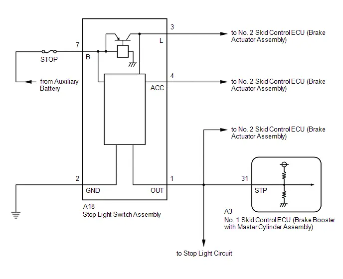
CAUTION / NOTICE / HINT
NOTICE:
- Inspect the fuses for circuits related to this system before performing the following procedure.
- Make sure to wait 5 minutes or more with the ignition switch turned off before removing the integration control supply or disconnecting any supply power circuit from the integration control supply, in order for the voltage to be discharged and self-diagnosis to run.
PROCEDURE
| 1. | CHECK STOP LIGHT OPERATION |
(a) Check that the stop lights come on when the brake pedal is depressed.
| Result | Proceed to |
|---|---|
| All stop lights illuminate when the brake pedal is depressed and turn off when the brake pedal is released. | A |
| All stop lights do not illuminate when the brake pedal is depressed. | B |
| One or more stop lights illuminate when the brake pedal is depressed but remain on when the brake pedal is released. | C |
| B |

| GO TO STEP 10 |
| C |

| GO TO STEP 6 |
|

| 2. | READ VALUE USING GTS (STOP LIGHT SW) |
(a) Check the value of Stop Light SW when the brake pedal is depressed.
Chassis > Brake Booster > Data List| Tester Display | Measurement Item | Range | Normal Condition | Diagnostic Note |
|---|---|---|---|---|
| Stop Light SW | Stop light switch assembly (STP terminal input) | OFF / ON | OFF: Brake pedal released ON: Brake pedal depressed | HINT: The brake pedal state is determined using the voltage at terminal STP |
| Tester Display |
|---|
| Stop Light SW |
| Result | Proceed to |
|---|---|
| The value of Stop Light SW is ON | A |
| None of the above conditions are met | B |
| B |

| GO TO STEP 9 |
|

| 3. | STOP LIGHT SWITCH ASSEMBLY OUTPUT CIRCUIT INSPECTION |
Pre-procedure1
(a) Turn the ignition switch off.
Procedure1
(b) Make sure that there is no looseness at the locking part and the connecting part of the connector.
OK:
The connector is securely connected.
Pre-procedure2
(c) Turn the ignition switch to ON.
Procedure2
| (d) Measure the voltage according to the value(s) in the table below. Standard Voltage:  Click Location & Routing(A18) Click Connector(A18) Click Location & Routing(A18) Click Connector(A18)
Result:
|
|
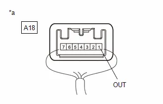
Post-procedure1
(e) None
| NG |

| GO TO STEP 6 |
|

| 4. | CLEAR DTC |
Pre-procedure1
(a) None
Procedure1
(b) Clear the DTCs.
Chassis > Brake Booster > Clear DTCsPost-procedure1
(c) Turn the ignition switch off.
|

| 5. | RECONFIRM DTC |
Pre-procedure1
(a) Based on the Freeze Frame Data and interview with the customer, attempt to reproduce the conditions when the malfunction occurred.
Procedure1
(b) Check if the same DTC is output.
Chassis > Brake Booster > Trouble Codes| Result | Proceed to |
|---|---|
| P057100 is not output | A |
| P057100 is output | B |
Post-procedure1
(c) None
| A |

| USE SIMULATION METHOD TO CHECK |
| B |

| REPLACE BRAKE BOOSTER WITH MASTER CYLINDER ASSEMBLY
|


| 6. | CHECK STOP LIGHT SWITCH ASSEMBLY |
Pre-procedure1
(a) Turn the ignition switch off.
Procedure1
(b) Make sure that there is no looseness at the locking part and the connecting part of the connector.
OK:
The connector is securely connected.
Pre-procedure2
(c) Disconnect the A18 stop light switch assembly connector.
Procedure2
(d) Check both the connector case and the terminals for deformation and corrosion.
OK:
No deformation or corrosion.
Procedure3
(e) Measure the voltage according to the value(s) in the table below.
Standard Voltage:
 Click Location & Routing(A18) Click Connector(A18)
 | Tester Connection | Condition | Specified Condition | Result |
|---|---|---|---|
| A18-1 (OUT) - Body ground | Stop light switch assembly off (Brake pedal released) | Below 1.5 V | V |
Post-procedure1
(f) None
| OK |

| REPLACE STOP LIGHT SWITCH ASSEMBLY |
|

| 7. | CHECK BRAKE BOOSTER WITH MASTER CYLINDER ASSEMBLY |
Procedure1
(a) Make sure that there is no looseness at the locking part and the connecting part of the connector.
OK:
The connector is securely connected.
Pre-procedure1
(b) Disconnect the A3 No. 1 skid control ECU (brake booster with master cylinder assembly) connector.
Procedure2
(c) Check both the connector case and the terminals for deformation and corrosion.
OK:
No deformation or corrosion.
Procedure3
(d) Measure the voltage according to the value(s) in the table below.
Standard Voltage:
 Click Location & Routing(A18) Click Connector(A18)
 | Tester Connection | Condition | Specified Condition | Result |
|---|---|---|---|
| A18-1 (OUT) - Body ground | Stop light switch assembly off (Brake pedal released) | Below 1.5 V | V |
Post-procedure1
(e) None
| OK |

| REPLACE BRAKE BOOSTER WITH MASTER CYLINDER ASSEMBLY
|


|

| 8. | CHECK FOR SHORT TO B IN STP CIRCUIT |
(a) Check that there is no short to B in the STP circuit (wire harnesses, connectors, ECUs and stop lights).
OK:
No short to B.
| OK |

| USE SIMULATION METHOD TO CHECK |
| NG |

| REPAIR OR REPLACE MALFUNCTIONING PART |
| 9. | CHECK HARNESS AND CONNECTOR (STP TERMINAL) |
Pre-procedure1
(a) Turn the ignition switch off.
Procedure1
(b) Make sure that there is no looseness at the locking part and the connecting part of the connector.
OK:
The connector is securely connected.
Pre-procedure2
(c) Disconnect the A3 No. 1 skid control ECU (brake booster with master cylinder assembly) connector.
Procedure2
(d) Check both the connector case and the terminals for deformation and corrosion.
OK:
No deformation or corrosion.
Procedure3
(e) Measure the voltage according to the value(s) in the table below.
Standard Voltage:
 Click Location & Routing(A3) Click Connector(A3)
 | Tester Connection | Condition | Specified Condition | Result |
|---|---|---|---|
| A3-31 (STP) - Body ground | Stop light switch assembly on (Brake pedal depressed) | 11 to 14 V | V |
Post-procedure1
(f) None
| OK |

| REPLACE BRAKE BOOSTER WITH MASTER CYLINDER ASSEMBLY
|


| NG |

| REPAIR OR REPLACE HARNESS OR CONNECTOR |
| 10. | CHECK HARNESS AND CONNECTOR (STOP LIGHT SWITCH ASSEMBLY - STOP LIGHT) |
(a) Check that there is no open in the wire harnesses and connectors from terminal OUT of the stop light switch assembly to the stop lights.
OK:
No open.
| OK |

| REPLACE BRAKE BOOSTER WITH MASTER CYLINDER ASSEMBLY
|


| NG |

| REPAIR OR REPLACE HARNESS OR CONNECTOR |
Brake Pedal Position Sensor "A" (P057A00,P05E062)
DESCRIPTION
Refer to DTC C110000.
Click here

| DTC No. | Detection Item | DTC Detection Condition | Trouble Area | MIL | DTC Output from | Priority | Note |
|---|---|---|---|---|---|---|---|
| P057A00 | Brake Pedal Position Sensor "A" | The difference in the SKS1 and SKS2 brake pedal stroke sensor assembly is invalid for 0.2 seconds or more. |
| Comes on | Brake Booster | A |
|
| P05E062 | Brake Pedal Position Sensor "A"/"B" Signal Compare Failure | The difference in change between sensor output voltage 1 (SKS1) and sensor output voltage 2 (SKS2) is excessively large for 0.2 seconds or more. |
| Comes on | Brake Booster | A |
|
MONITOR DESCRIPTION
- When the No. 2 skid control ECU (brake actuator assembly) detects that the difference between the brake pedal stroke sensor 1 and brake pedal stroke sensor 2 is invalid, the MIL is illuminated and a DTC is stored.
-
The No. 2 skid control ECU (brake actuator assembly) monitors the output value of the brake pedal stroke sensor assembly.
When the ratio between the output of brake pedal stroke sensor 1 and brake pedal stroke sensor 2 is outside the normal range, the No. 2 skid control ECU (brake actuator assembly) judges that the brake pedal stroke sensor assembly is malfunctioning, the MIL is illuminated and a DTC is stored.
MONITOR STRATEGY
| Related DTCs | P057A: Brake pedal position sensor invalid data P05E0: Brake pedal position sensor "A"/"B" correlation |
| Required Sensors/Components(Main) | Brake pedal stroke sensor assembly |
| Required Sensors/Components(Related) | No. 2 skid control ECU (brake actuator assembly) Brake pedal stroke sensor assembly |
| Frequency of Operation | Continuous |
| Duration | 0.198 seconds |
| MIL Operation | Immediately |
| Sequence of Operation | None |
TYPICAL ENABLING CONDITIONS
P057A| Monitor runs whenever the following DTCs are not stored | C1100 (Case 1): Brake pedal position sensor voltage circuit/open C1103 (Case 1): Brake pedal position sensor voltage circuit/open C1103 (Case 2): Brake pedal position sensor invalid data P057C: Brake pedal position sensor open circuit P057D: Brake pedal position sensor circuit high P057E: Brake pedal position sensor intermittent/erratic P05DD: Brake pedal position sensor circuit open P05DE: Brake pedal position sensor circuit high P05DF: Brake pedal position sensor intermittent/erratic P05E0: Brake pedal position sensor "A"/"B" correlation U0129: Lost communication with BSCM (CH1) |
| All of the following conditions are met | A, B, C, D, E, F and G |
| A. Both of the following conditions are met | More than 0.198 seconds |
| BS cut MOS | Valid |
| BS cut MOS voltage | Higher than 7.4 V |
| B. Up/Downstream communication | Valid |
| C. Following condition is met | More than 0.22 seconds |
| BS (linear) voltage | 8.5 V or higher |
| D. BS cut MOS voltage | Higher than 7.8 V |
| E. BS voltage | 9.5 V or higher |
| F. IGR voltage | Higher than 10 V |
| G. IGP voltage | Higher than 10 V |
| Monitor runs whenever the following DTCs are not stored | C1100 (Case 1): Brake pedal position sensor voltage circuit/open C1100 (Case 2): Brake pedal position sensor invalid data C1103 (Case 1): Brake pedal position sensor voltage circuit/open C1103 (Case 2): Brake pedal position sensor invalid data P057A: Brake pedal position sensor invalid data P057C: Brake pedal position sensor open circuit P057D: Brake pedal position sensor circuit high P057E: Brake pedal position sensor intermittent/erratic P05DD: Brake pedal position sensor circuit open P05DE: Brake pedal position sensor circuit high P05DF: Brake pedal position sensor intermittent/erratic U0129: Lost communication with BSCM (CH1) |
| All of the following conditions are met | A, B, C, D, E, F and G |
| A. Both of the following conditions are met | More than 0.198 seconds |
| BS cut MOS | Valid |
| BS cut MOS voltage | Higher than 7.4 V |
| B. Up/Downstream communication | Valid |
| C. Following condition is met | More than 0.22 seconds |
| BS (linear) voltage | 8.5 V or higher |
| D. BS cut MOS voltage | Higher than 7.8 V |
| E. BS voltage | 9.5 V or higher |
| F. IGR voltage | Higher than 10 V |
| G. IGP voltage | Higher than 10 V |
TYPICAL MALFUNCTION THRESHOLDS
P057A| Following condition is met | More than 0.018 seconds |
| Power supply voltage ratio (SKS1/VSK1) and Power supply voltage ratio (SKS2/VSK2) aren't in correlation area | - |
| Power supply voltage ratio (SKS1/VSK1) and Power supply voltage ratio (SKS2/VSK2) aren't in correlation area | - |
COMPONENT OPERATING RANGE
P057A| All of the following conditions are met | A, B, C and D |
| A. Both of the following conditions are met | More than 0.198 seconds |
| BS cut MOS | Valid |
| BS cut MOS voltage | Higher than 7.4 V |
| B. Up/Downstream communication | Valid |
| C. Following condition is met | More than 0.22 seconds |
| BS (linear) voltage | 8.5 V or higher |
| D. Following condition is met | More than 0.024 seconds |
| Power supply voltage ratio (SKS1/VSK1) and Power supply voltage ratio (SKS2/VSK2) are in correlation area | - |
| All of the following conditions are met | A, B, C, D, E, F and G |
| A. Both of the following conditions are met | More than 0.198 seconds |
| BS cut MOS | Valid |
| BS cut MOS voltage | Higher than 7.4 V |
| B. Up/Downstream communication | Valid |
| C. Following condition is met | More than 0.22 seconds |
| BS (linear) voltage | 8.5 V or higher |
| D. Both of the following conditions are met | - |
| Power supply voltage ratio (SKS1/VSK1) | More than 0.2 |
| Power supply voltage ratio (SKS2/VSK2) | Less than 0.8 |
| E. Both of the following conditions are met | - |
| Power supply voltage ratio (SKS1/VSK1) | More than 0.23 |
| Power supply voltage ratio (SKS2/VSK2) | Less than 0.77 |
| F. Both of the following conditions are met | - |
| Power supply voltage ratio (SKS1/VSK1) | More than 0.26 |
| Power supply voltage ratio (SKS2/VSK2) | Less than 0.74 |
| G. Normal status experience at high voltage | On |
CONFIRMATION DRIVING PATTERN
NOTICE:
When performing the normal judgment procedure, make sure that the driver door is closed and is not opened at any time during the procedure.
HINT:
- After repair has been completed, clear the DTC and then check that the Toyota Prius vehicle has returned to normal by performing the following All Readiness check procedure.
- When clearing the permanent DTCs, refer to the "CLEAR PERMANENT DTC" procedure.
- Connect the GTS to the DLC3.
- Turn the ignition switch to ON and turn the GTS on.
- Clear the DTCs (even if no DTCs are stored, perform the clear DTC procedure).
- Turn the ignition switch off.
- Turn the ignition switch to ON (READY) and turn the GTS on.
-
Fully depress the brake pedal. [*]
HINT:
[*]: Normal judgment procedure.
The normal judgment procedure is used to complete DTC judgment and also used when clearing permanent DTCs.
-
Enter the following menus: Chassis / Brake/EPB* / Utility / All Readiness.
*: Electric Parking Brake System
-
Check the DTC judgment result.
HINT:
- If the judgment result shows NORMAL, the system is normal.
- If the judgment result shows ABNORMAL, the system has a malfunction.
- If the judgment result shows INCOMPLETE, perform driving pattern again.
WIRING DIAGRAM
Refer to DTC C110000.
Click here

CAUTION / NOTICE / HINT
NOTICE:
Make sure to wait 5 minutes or more with the ignition switch turned off before removing the integration control supply or disconnecting any supply power circuit from the integration control supply, in order for the voltage to be discharged and self-diagnosis to run.
PROCEDURE
| 1. | READ VALUE USING GTS (BRAKE PEDAL STROKE SENSOR ASSEMBLY) |
Pre-procedure1
(a) Mount a pedal effort gauge.
(b) Turn the ignition switch to ON (READY) and depress the brake pedal once.
HINT:
Depress the brake pedal after turning the ignition switch to ON (READY) to set the Toyota Prius vehicle to linear mode (switching solenoid (SSA) on).
Procedure1
(c) Depress the brake pedal slowly and check the brake pedal stroke sensor assembly output voltages with respect to brake pedal depression force.
Chassis > Brake Booster > Data List| Tester Display | Measurement Item | Range | Normal Condition | Diagnostic Note |
|---|---|---|---|---|
| Stroke Sensor | Brake pedal stroke sensor 1 | Min.: 0.0 V Max.: 5.0 V | Brake pedal released: 0.6 to 1.4 V | Reading increases when brake pedal is depressed |
| Tester Display |
|---|
| Stroke Sensor |
| Tester Display | Measurement Item | Range | Normal Condition | Diagnostic Note |
|---|---|---|---|---|
| Stroke Sensor2 | Brake pedal stroke sensor 2 | Min.: 0.0 V Max.: 5.0 V | Brake pedal released: 3.6 to 4.4 V | Reading decreases when brake pedal is depressed |
| Tester Display |
|---|
| Stroke Sensor2 |
HINT:
Perform this procedure in linear mode (switching solenoid (SSA) on).
Standard Voltage:
| Brake Effort [N (kgf, lbf)] | Stroke Sensor [V] | Stroke Sensor2 [V] |
|---|---|---|
| 50 (5, 11.2) | 0.96 to 1.67 | 3.33 to 4.04 |
| 100 (10, 22.5) | 1.14 to 1.86 | 3.14 to 3.86 |
| 150 (15, 33.7) | 1.23 to 1.95 | 3.05 to 3.77 |
| Result | Proceed to |
|---|---|
| OK | A |
| NG (brake pedal stroke sensor 1) | B |
| NG (brake pedal stroke sensor 2) | C |
Post-procedure1
(d) None
| A |

| USE SIMULATION METHOD TO CHECK |
| C |

| GO TO STEP 3 |
|

| 2. | CHECK HARNESS AND CONNECTOR (BRAKE BOOSTER WITH MASTER CYLINDER ASSEMBLY - BRAKE PEDAL STROKE SENSOR ASSEMBLY) |
Pre-procedure1
(a) Turn the ignition switch off.
Procedure1
(b) Make sure that there is no looseness at the locking part and the connecting part of the connectors.
OK:
The connector is securely connected.
Pre-procedure2
(c) Disconnect the A3 No. 1 skid control ECU (brake booster with master cylinder assembly) connector.
(d) Disconnect the A5 brake pedal stroke sensor assembly connector.
Procedure2
(e) Check both the connector case and the terminals for deformation and corrosion.
OK:
No deformation or corrosion.
Procedure3
(f) Measure the resistance according to the value(s) in the table below.
Standard Resistance:
 Click Location & Routing(A3,A5) Click Connector(A3) Click Connector(A5)
 | Tester Connection | Condition | Specified Condition | Result |
|---|---|---|---|
| A3-29 (SKS1) - A5-6 (SKS1) | Always | Below 1 Ω | Ω |
| A3-29 (SKS1) or A5-6 (SKS1) - Body ground | Always | 10 kΩ or higher | kΩ |
Post-procedure1
(g) None
| OK |

| REPLACE BRAKE PEDAL STROKE SENSOR ASSEMBLY
|


| NG |

| REPAIR OR REPLACE HARNESS OR CONNECTOR |
| 3. | CHECK HARNESS AND CONNECTOR (BRAKE ACTUATOR ASSEMBLY - BRAKE PEDAL STROKE SENSOR ASSEMBLY) |
Pre-procedure1
(a) Turn the ignition switch off.
Procedure1
(b) Make sure that there is no looseness at the locking part and the connecting part of the connectors.
OK:
The connector is securely connected.
Pre-procedure2
(c) Disconnect the A4 No. 2 skid control ECU (brake actuator assembly) connector.
(d) Disconnect the A5 brake pedal stroke sensor assembly connector.
Procedure2
(e) Check both the connector case and the terminals for deformation and corrosion.
OK:
No deformation or corrosion.
Procedure3
(f) Measure the resistance according to the value(s) in the table below.
Standard Resistance:
 Click Location & Routing(A4,A5) Click Connector(A4) Click Connector(A5)
 | Tester Connection | Condition | Specified Condition | Result |
|---|---|---|---|
| A4-10 (SKS2) - A5-1 (SKS2) | Always | Below 1 Ω | Ω |
| A4-10 (SKS2) or A5-1 (SKS2) - Body ground | Always | 10 kΩ or higher | kΩ |
Post-procedure1
(g) None
| OK |

| REPLACE BRAKE PEDAL STROKE SENSOR ASSEMBLY
|


| NG |

| REPAIR OR REPLACE HARNESS OR CONNECTOR |
Brake Pedal Position Sensor "A" Circuit Short to Battery (P057A12,P057A14,P057A1F)
DESCRIPTION
Refer to DTC C110000.
Click here

| DTC No. | Detection Item | DTC Detection Condition | Trouble Area | MIL | DTC Output from | Priority | Note |
|---|---|---|---|---|---|---|---|
| P057A12 | Brake Pedal Position Sensor "A" Circuit Short to Battery | The sensor output voltage 1 (SKS1) is 4.7 V or more for 0.2 seconds or more. |
| Comes on | Brake Booster | A |
|
| P057A14 | Brake Pedal Position Sensor "A" Circuit Short to Ground or Open | The sensor output voltage 1 (SKS1) is less than 0.3 V for 0.2 seconds or more. |
| Comes on | Brake Booster | A |
|
| P057A1F | Brake Pedal Position Sensor "A" Circuit Intermittent | The difference between the current value and previous value of the sensor output voltage 1 (SKS1) is 8.5% or more for 0.2 seconds or more. |
| Comes on | Brake Booster | A |
|
MONITOR DESCRIPTION
The No. 2 skid control ECU (brake actuator assembly) monitors the output value of the brake pedal stroke sensor assembly, and if the following conditions are detected, the No. 2 skid control ECU (brake actuator assembly) judges that the brake pedal stroke sensor assembly has a malfunction and illuminates the MIL and stores a DTC.
-
The power supply voltage ratio of the brake pedal stroke sensor 1 is outside the normal range.
HINT:
The power supply voltage ratio is the ratio of the voltage of SKS1 and VSK1.
-
The difference between the current power supply voltage ratio and the previous power supply voltage ratio of the brake pedal stroke sensor 1 exceeds a specific value (improbable sudden change repeats).
HINT:
The power supply voltage ratio is the ratio of the voltage of SKS1 and VSK1.
MONITOR STRATEGY
| Related DTCs | P057C: Brake pedal position sensor open circuit P057D: Brake pedal position sensor circuit high P057E: Brake pedal position sensor intermittent/erratic |
| Required Sensors/Components(Main) | No. 2 skid control ECU (brake actuator assembly) |
| Required Sensors/Components(Related) | No. 2 skid control ECU (brake actuator assembly) |
| Frequency of Operation | Continuous |
| Duration | 0.198 seconds |
| MIL Operation | Immediately |
| Sequence of Operation | None |
TYPICAL ENABLING CONDITIONS
All| Monitor runs whenever the following DTCs are not stored | C1100 (Case 1): Brake pedal position sensor voltage circuit/open C1100 (Case 2): Brake pedal position sensor invalid data |
| All of the following conditions are met | - |
| Brake pedal position sensor1 power supply | 4.8 V or higher, and 5.2 V or less |
| VCSK | Valid |
TYPICAL MALFUNCTION THRESHOLDS
P057C| Following condition is met | More than 0.018 seconds |
| Brake pedal position sensor1 power supply voltage ratio (SKS1/VSK1) | Below 0.06 |
| Following condition is met | More than 0.018 seconds |
| Brake pedal position sensor1 power supply voltage ratio (SKS1/VSK1) | Higher than 0.94 |
| Absolute value of the change in (SKS1/VSK1) during 6millisec | More than 0.0848 |
COMPONENT OPERATING RANGE
P057C and P057D| All of the following conditions are met | A, B, C and D |
| A. Brake pedal position sensor1 power supply | 4.8 V or higher, and 5.2 V or less |
| B. VCSK | Valid |
| C. Following condition is met | More than 0.018 seconds |
| Brake pedal position sensor1 power supply voltage ratio (SKS1/VSK1) | 0.06 or higher |
| D. Following condition is met | More than 0.018 seconds |
| Brake pedal position sensor1 power supply voltage ratio (SKS1/VSK1) | 0.94 or less |
| All of the following conditions are met | - |
| Brake pedal position sensor1 power supply | 4.8 V or higher, and 5.2 V or less |
| VCSK | Valid |
| Absolute value of the change in (SKS1/VSK1) during 6millisec | 0.0848 or less |
CONFIRMATION DRIVING PATTERN
NOTICE:
When performing the normal judgment procedure, make sure that the driver door is closed and is not opened at any time during the procedure.
HINT:
- After repair has been completed, clear the DTC and then check that the Toyota Prius vehicle has returned to normal by performing the following All Readiness check procedure.
- When clearing the permanent DTCs, refer to the "CLEAR PERMANENT DTC" procedure.
- Connect the GTS to the DLC3.
- Turn the ignition switch to ON and turn the GTS on.
- Clear the DTCs (even if no DTCs are stored, perform the clear DTC procedure).
- Turn the ignition switch off.
- Turn the ignition switch to ON (READY) and turn the GTS on.
-
Wait for 1 second or more. [*]
HINT:
[*]: Normal judgment procedure.
The normal judgment procedure is used to complete DTC judgment and also used when clearing permanent DTCs.
-
Enter the following menus: Chassis / Brake/EPB* / Utility / All Readiness.
*: Electric Parking Brake System
-
Check the DTC judgment result.
HINT:
- If the judgment result shows NORMAL, the system is normal.
- If the judgment result shows ABNORMAL, the system has a malfunction.
- If the judgment result shows INCOMPLETE, perform driving pattern again.
WIRING DIAGRAM
Refer to DTC C110000.
Click here

CAUTION / NOTICE / HINT
NOTICE:
Make sure to wait 5 minutes or more with the ignition switch turned off before removing the integration control supply or disconnecting any supply power circuit from the integration control supply, in order for the voltage to be discharged and self-diagnosis to run.
PROCEDURE
| 1. | CHECK BRAKE PEDAL |
(a) Check that the brake pedal and the brake pedal stroke sensor assembly are properly installed and that the pedal can be depressed normally.
(b) Check and adjust the brake pedal height.
HINT:
Click here

(c) Adjust the brake pedal stroke sensor assembly.
HINT:
Click here

|

| 2. | CHECK HARNESS AND CONNECTOR (BRAKE BOOSTER WITH MASTER CYLINDER ASSEMBLY - BRAKE PEDAL STROKE SENSOR ASSEMBLY) |
Pre-procedure1
(a) Turn the ignition switch off.
Procedure1
(b) Make sure that there is no looseness at the locking part and the connecting part of the connectors.
OK:
The connector is securely connected.
Pre-procedure2
(c) Disconnect the A3 No. 1 skid control ECU (brake booster with master cylinder assembly) connector.
(d) Disconnect the A5 brake pedal stroke sensor assembly connector.
Procedure2
(e) Check both the connector case and the terminals for deformation and corrosion.
OK:
No deformation or corrosion.
Procedure3
(f) Measure the resistance according to the value(s) in the table below.
Standard Resistance:
 Click Location & Routing(A3,A5) Click Connector(A3) Click Connector(A5)
 | Tester Connection | Condition | Specified Condition | Result |
|---|---|---|---|
| A3-29 (SKS1) - A5-6 (SKS1) | Always | Below 1 Ω | Ω |
| A3-29 (SKS1) or A5-6 (SKS1) - Body ground | Always | 10 kΩ or higher | kΩ |
Post-procedure1
(g) None
| OK |

| REPLACE BRAKE PEDAL STROKE SENSOR ASSEMBLY
|


| NG |

| REPAIR OR REPLACE HARNESS OR CONNECTOR |
Lost Communication with Drive Motor Control Module "A" (U011000,U012987,U029300,U110600,U114A00,U115000,U117D87)
DESCRIPTION
The No. 1 skid control ECU (brake booster with master cylinder assembly) communicates with the following ECUs and sensors via CAN communication.
- No. 2 skid control ECU (brake actuator assembly)
- Inverter with converter assembly
- Hybrid Toyota Prius vehicle control ECU
- Integration control supply
| DTC No. | Detection Item | DTC Detection Condition | Trouble Area | MIL | DTC Output from | Priority | Note |
|---|---|---|---|---|---|---|---|
| U011000 | Lost Communication with Drive Motor Control Module "A" | When terminal IGR voltage is 9.5 V or more, data from the inverter with converter assembly cannot be received for 2 seconds or more. |
| Comes on | Brake Booster | B |
|
| U012987 | Lost Communication with Brake System Control Module "A" Missing Message | When the voltage at terminal IGR is 9.5 V or more, communication between the No. 1 skid control ECU (brake booster with master cylinder assembly) and No. 2 skid control ECU (brake actuator assembly) is not possible for 2 seconds or more. |
| Comes on | Brake Booster | B |
|
| U029300 | Lost Communication with Hybrid/EV Powertrain Control Module | When terminal IGR voltage is 9.5 V or more, data from the hybrid Toyota Prius vehicle control ECU cannot be received for 2 seconds or more. |
| Comes on | Brake Booster | B |
|
| U110600 | Lost Communication with Electric Parking Brake Module | With terminal IGR voltage at 9.5 V or more, data cannot be received from the No. 2 skid control ECU (brake actuator assembly) for 1 second or more. |
| Does not come on | Brake Booster | B | Output ECU: No. 1 skid control ECU (brake booster with master cylinder assembly) |
| U114A00 | Lost Communication with Sub Battery System (System 2) Missing Message | When terminal IGR voltage is 9.5 V or more, data from the integration control supply cannot be received for 2 seconds or more. |
| Does not come on | Brake Booster | B | Output ECU: No. 1 skid control ECU (brake booster with master cylinder assembly) |
| U115000 | Lost Communication with Hybrid Powertrain Control Module (ch2) | When terminal IGR voltage is 9.5 V or more, data from the hybrid Toyota Prius vehicle control ECU cannot be received for 2 seconds or more. |
| Comes on | Brake Booster | B |
|
| U117D87 | Lost Communication with Brake System Control Module (ch4) Missing Message | When the voltage at terminal IGR is 9.5 V or more, communication between the No. 1 skid control ECU (brake booster with master cylinder assembly) and No. 2 skid control ECU (brake actuator assembly) is not possible for 2 seconds or more. |
| Comes on | Brake Booster | B |
|
MONITOR DESCRIPTION
U0110, U0129, U0293, U1150 and U117D:
When a communication error with any ECU or sensor continues for a certain amount of time or communication is unstable (communication is invalid for a certain amount of time a certain amount of times), the No. 2 skid control ECU (brake actuator assembly) judges that communication with the respective ECU is abnormal and illuminates the MIL and stores a DTC.
MONITOR STRATEGY
| Related DTCs | U0110: Lost communication with DMCM "A" (CH2) U0129: Lost communication with BSCM (CH1) U0293: Lost communication with HPCM (CH1) U1150: Lost communication with HPCM (CH2) U117D: Lost communication with BSCM (CH2) |
| Required Sensors/Components(Main) | No. 2 skid control ECU (brake actuator assembly) |
| Required Sensors/Components(Related) | No. 2 skid control ECU (brake actuator assembly) |
| Frequency of Operation | Continuous |
| Duration | 2 seconds |
| MIL Operation | Immediately |
| Sequence of Operation | None |
TYPICAL ENABLING CONDITIONS
U0110| Monitor runs whenever the following DTCs are not stored | C14C8: Brake system voltage circuit high U0293: Lost communication with HPCM (CH1) |
| All of the following conditions are met | A, B, C, D, E and F |
| A. Both of the following conditions a and b are met | More than 1 second |
| a. Both of the following conditions are met | More than 0.198 seconds |
| BS cut MOS | Valid |
| BS cut MOS voltage | Higher than 7.4 V |
| b. Both of the following conditions are met | More than 0.012 seconds |
| BS cut MOS | Valid |
| BS cut MOS voltage | Below 23.2 V |
| B. CAN communication status | Enable |
| C. Following condition is met | More than 3 seconds |
| IGP_PT2 voltage | Higher than 9.5 V |
| D. Following condition is met | More than 3 seconds |
| IGR voltage | Higher than 9.5 V |
| E. Following condition is met | More than 3 seconds |
| IGP_PT2 | On |
| F. BS cut MOS voltage | Higher than 7.8 V |
| Monitor runs whenever the following DTCs are not stored | C14C8: Brake system voltage circuit high |
| All of the following conditions are met | A, B, C, D and E |
| A. Both of the following conditions a and b are met | More than 1 second |
| a. Both of the following conditions are met | More than 0.198 seconds |
| BS cut MOS | Valid |
| BS cut MOS voltage | Higher than 7.4 V |
| b. Both of the following conditions are met | More than 0.012 seconds |
| BS cut MOS | Valid |
| BS cut MOS voltage | Below 23.2 V |
| B. CAN communication status | Enable |
| C. Following condition is met | More than 3 seconds |
| IGR voltage | Higher than 9.5 V |
| D. Following condition is met | More than 3 seconds |
| IGR | On |
| E. BS cut MOS voltage | Higher than 7.8 V |
| Monitor runs whenever the following DTCs are not stored | C14C8: Brake system voltage circuit high |
| All of the following conditions are met | A, B, C, D and E |
| A. Both of the following conditions a and b are met | More than 1 second |
| a. Both of the following conditions are met | More than 0.198 seconds |
| BS cut MOS | Valid |
| BS cut MOS voltage | Higher than 7.4 V |
| b. Both of the following conditions are met | More than 0.012 seconds |
| BS cut MOS | Valid |
| BS cut MOS voltage | Below 23.2 V |
| B. CAN communication status | Enable |
| C. Both of the following conditions are met | More than 3 seconds |
| IGR voltage | Higher than 9.5 V |
| IGP_PT2 voltage | Higher than 9.5 V |
| D. Both of the following conditions are met | More than 3 seconds |
| IGR | On |
| IGP_PT2 | On |
| E. BS cut MOS voltage | Higher than 7.8 V |
| Monitor runs whenever the following DTCs are not stored | C14C8: Brake system voltage circuit high U0293: Lost communication with HPCM (CH1) |
| All of the following conditions are met | A, B, C, D, E and F |
| A. Both of the following conditions a and b are met | More than 1 second |
| a. Both of the following conditions are met | More than 0.198 seconds |
| BS cut MOS | Valid |
| BS cut MOS voltage | Higher than 7.4 V |
| b. Both of the following conditions are met | More than 0.012 seconds |
| BS cut MOS | Valid |
| BS cut MOS voltage | Below 23.2 V |
| B. CAN communication status | Enable |
| C. Both of the following conditions are met | More than 3 seconds |
| IGR voltage | Higher than 9.5 V |
| IGP_PT2 voltage | Higher than 9.5 V |
| D. Both of the following conditions are met | More than 3 seconds |
| IGR | On |
| IGP_PT2 | On |
| E. BS cut MOS voltage | Higher than 7.8 V |
TYPICAL MALFUNCTION THRESHOLDS
U0110| Either of the following conditions is met | A or B |
| A. Following condition is met | More than 3 times |
| Communication reception with inverter with converter assembly "A" (CH2) | Delayed |
| B. Checksum error exist with inverter with converter assembly "A" (CH2) | - |
| Either of the following conditions is met | A or B |
| A. Following condition is met | More than 3 times |
| Communication reception with No. 2 skid control ECU (brake actuator assembly) (CH1) | Delayed |
| B. Checksum error exist with No. 2 skid control ECU (brake actuator assembly) (CH1) | - |
| Either of the following conditions is met | A or B |
| A. Following condition is met | More than 3 times |
| Communication reception with hybrid Toyota Prius vehicle control ECU (CH1) | Delayed |
| B. Checksum error exist with hybrid vehicle control ECU (CH1) | - |
| Either of the following conditions is met | A or B |
| A. Following condition is met | More than 3 times |
| Communication reception with hybrid Toyota Prius vehicle control ECU (CH2) | Delayed |
| B. Checksum error exist with hybrid vehicle control ECU (CH2) | - |
| Either of the following conditions is met | A or B |
| A. Following condition is met | More than 3 times |
| Communication reception with No. 2 skid control ECU (brake actuator assembly) (CH2) | Delayed |
| B. Checksum error exist with No. 2 skid control ECU (brake actuator assembly) (CH2) | - |
COMPONENT OPERATING RANGE
U0110| Both of the following conditions are met | - |
| Communication reception with inverter with converter assembly "A" (CH2) | Not delayed |
| No checksum error with inverter with converter assembly "A" (CH2) | - |
| Both of the following conditions are met | - |
| Communication reception with No. 2 skid control ECU (brake actuator assembly) (CH1) | Not delayed |
| No checksum error with No. 2 skid control ECU (brake actuator assembly) (CH1) | - |
| Both of the following conditions are met | - |
| Communication reception with hybrid Toyota Prius vehicle control ECU (CH1) | Not delayed |
| No checksum error with hybrid vehicle control ECU (CH1) | - |
| Both of the following conditions are met | - |
| Communication reception with hybrid Toyota Prius vehicle control ECU (CH2) | Not delayed |
| No checksum error with hybrid vehicle control ECU (CH2) | - |
| Both of the following conditions are met | - |
| Communication reception with No. 2 skid control ECU (brake actuator assembly) (CH2) | Not delayed |
| No checksum error with No. 2 skid control ECU (brake actuator assembly) (CH2) | - |
CONFIRMATION DRIVING PATTERN
NOTICE:
When performing the normal judgment procedure, make sure that the driver door is closed and is not opened at any time during the procedure.
HINT:
- After repair has been completed, clear the DTC and then check that the Toyota Prius vehicle has returned to normal by performing the following All Readiness check procedure.
- When clearing the permanent DTCs, refer to the "CLEAR PERMANENT DTC" procedure.
- Connect the GTS to the DLC3.
- Turn the ignition switch to ON and turn the GTS on.
- Clear the DTCs (even if no DTCs are stored, perform the clear DTC procedure).
- Turn the ignition switch off.
- Turn the ignition switch to ON (READY) and turn the GTS on.
-
Wait for 60 seconds or more. [*]
HINT:
[*]: Normal judgment procedure.
The normal judgment procedure is used to complete DTC judgment and also used when clearing permanent DTCs.
-
Enter the following menus: Chassis / Brake/EPB* / Utility / All Readiness.
*: Electric Parking Brake System
-
Check the DTC judgment result.
HINT:
- If the judgment result shows NORMAL, the system is normal.
- If the judgment result shows ABNORMAL, the system has a malfunction.
- If the judgment result shows INCOMPLETE, perform driving pattern again.
PROCEDURE
| 1. | CHECK DTC (HEALTH CHECK) |
(a) Perform the Health Check using the GTS.
| Result | Proceed to |
|---|---|
| DTCs for related systems are output together with DTC U011000, U012987, U029300, U110600, U114A00, U115000 or U117D87. | A |
| DTC U011000, U012987, U029300, U110600, U114A00, U115000 or U117D87 is output. | B |
| DTCs are not output. | C |
| A |

| GO TO DIAGNOSTIC TROUBLE CODE CHART (RELATED SYSTEM) |
| B |

| INSPECT CAN COMMUNICATION SYSTEM for HEV Model: Click here
for PHEV Model: Click here
|


| C |

| USE SIMULATION METHOD TO CHECK |
Brake Hold Standby Indicator Light Circuit
DESCRIPTION
The brake hold standby indicator light turns on if brake hold control is possible when the following conditions required for operation standby are met and the brake hold switch (electric parking brake switch assembly) is pressed while the ignition switch is turned to ON.
-
Conditions required for operation standby:
- The driver door is closed.
- The driver seat belt is fastened.
- The system is normal.
WIRING DIAGRAM
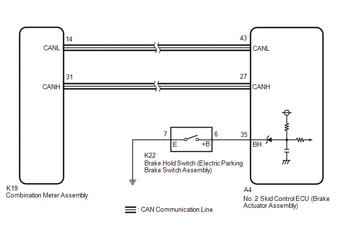
PROCEDURE
| 1. | PRE-CHECK |
(a) If the brake hold standby indicator light does not illuminate even though the brake hold switch (electric parking brake switch assembly) is pushed, check that the brake hold function operation conditions are met.
- The driver door is closed.
- The driver seat belt is fastened.
- The system is normal.
HINT:
If a malfunction occurs in one of the following systems, the brake hold operated indicator light will blink. If this occurs, perform troubleshooting on the malfunctioning system.
- Electronically controlled brake system
- Electric parking brake system
- Hybrid control system
|

| 2. | READ VALUE USING GTS (BRAKE HOLD READY) |
(a) Check the brake hold standby indicator light and mode condition on the GTS changes according to brake hold switch (electric parking brake switch assembly) operation.
Chassis > Brake/EPB > Data List| Tester Display | Measurement Item | Range | Normal Condition | Diagnostic Note |
|---|---|---|---|---|
| Brake Hold Ready | Brake hold control permission status | Not in stand-by mode / Stand-by mode | Not in stand-by mode: Brake hold function not operating (brake hold standby indicator light not illuminated) Stand-by mode: Brake hold function stand-by state (brake hold standby indicator light illuminated) | - |
| Tester Display |
|---|
| Brake Hold Ready |
Standard:
| Brake Hold Switch (Electric Parking Brake Switch Assembly) Operation | Mode Condition Display | Brake Hold Standby Indicator Light |
|---|---|---|
| Not pressed | Not in stand-by mode | Does not come on |
| Pressing the brake hold switch (electric parking brake switch assembly) | Stand-by mode | Comes on |
| Result | Proceed to |
|---|---|
| Indicator light and mode condition display do not change. | A |
| Mode condition display is normal, but indicator light does not change. | B |
| Indicator light and mode condition display are normal. | C |
| B |

| INSPECT METER / GAUGE SYSTEM |
| C |

| USE SIMULATION METHOD TO CHECK |
|

| 3. | INSPECT ELECTRIC PARKING BRAKE SWITCH ASSEMBLY |
(a) Turn the ignition switch off.
(b) Inspect the brake hold switch (electric parking brake switch assembly).
Click here

OK:
The brake hold switch (electric parking brake switch assembly) is normal.
| NG |

| REPLACE ELECTRIC PARKING BRAKE SWITCH ASSEMBLY |
|

| 4. | CHECK HARNESS AND CONNECTOR (BRAKE ACTUATOR ASSEMBLY - ELECTRIC PARKING BRAKE SWITCH ASSEMBLY) |
(a) Make sure that there is no looseness at the locking part and the connecting part of the connector.
OK:
The connector is securely connected.
(b) Disconnect the A4 No. 2 skid control ECU (brake actuator assembly) connector.
(c) Check both the connector case and the terminals for deformation and corrosion.
OK:
No deformation or corrosion.
(d) Measure the resistance according to the value(s) in the table below.
Standard Resistance:
 Click Location & Routing(A4,K22) Click Connector(A4) Click Connector(K22)
 | Tester Connection | Condition | Specified Condition |
|---|---|---|
| A4-35 (BH) - K22-6 ( B) | Always | Below 1 Ω |
| A4-35 (BH) or K22-6 ( B) - Body ground | Always | 10 kΩ or higher |
| K22-7 (E) - Body ground | 1 minute or more after disconnecting the cable from the negative (-) auxiliary battery terminal | Below 1 Ω |
| OK |

| REPLACE BRAKE ACTUATOR ASSEMBLY |
| NG |

| REPAIR OR REPLACE HARNESS OR CONNECTOR |
Brake Hold Operated Indicator Light Circuit
DESCRIPTION
The brake hold operated indicator light illuminates when the brake hold system is operating (vehicle stopped due to brake fluid pressure hold) and turns off when the brake hold system operation is finished (brake fluid pressure decreases).
The brake hold system may not operate depending on Toyota Prius vehicle conditions even when the system is in standby mode and the brake hold standby indicator light is illuminated.
If there is a system malfunction that causes brake hold control to be prohibited, when the vehicle is under the following conditions and the brake hold switch (electric parking brake switch assembly) is pressed, the brake hold operated indicator light blinks.
-
Toyota Prius Vehicle Conditions:
- The driver door is closed.
- The driver seat belt is fastened.
HINT:
- When the ignition switch is turned off during brake hold operation, control stops.
-
If brake hold control does not operate even when the Toyota Prius vehicle stops, depress the brake pedal again firmly to stop the vehicle.
If brake hold control still does not operate, confirm the conditions for brake hold control to operate.
PROCEDURE
| 1. | PRE-CHECK |
(a) Check that the brake hold standby indicator light operates normally.
Click here


(b) If the brake hold operated indicator light does not illuminate even though the brake hold standby indicator light is illuminated, check that the following brake hold operation (brake fluid pressure is being maintained) conditions are met.
- System is in operation standby state (brake hold standby indicator light is illuminated).
- Shift position is not P or R.
- Driver is depressing brake pedal and Toyota Prius vehicle is fully stopped.
- Driver is not depressing accelerator pedal.
- Vehicle is not on steep decline.
- The parking brake is not engaged.
HINT:
If a malfunction occurs in one of the following systems, the brake hold operated indicator light will blink. If this occurs, perform troubleshooting on the malfunctioning system.
- Electronically controlled brake system
- Electric parking brake system
- Hybrid control system
| NEXT |

| INSPECT METER / GAUGE SYSTEM
|


Steering Angle Sensor Wrong Installation (X0455)
DESCRIPTION
| Code | Tester Display | Measurement Item | Trouble Area | Output ECU |
|---|---|---|---|---|
| X0455 | Steering Angle Sensor Wrong Installation | History of steering angle sensor being installed incorrectly |
| No. 2 skid control ECU (brake actuator assembly) |
CAUTION / NOTICE / HINT
NOTICE:
After performing the inspection, check and clear the Toyota Prius vehicle control history (RoB).
HINT:
When Steering Angle Sensor Wrong Installation (X0455) is stored, output control may operate, but this is not a malfunction.
PROCEDURE
| 1. | CHECK DTC (HEALTH CHECK) |
(a) Perform the Health Check using the GTS.
| Result | Proceed to |
|---|---|
| DTCs are not output. | A |
| DTCs are output. | B |
| B |

| GO TO DIAGNOSTIC TROUBLE CODE CHART |
|

| 2. | ALIGN FRONT WHEELS FACING STRAIGHT AHEAD |
|

| 3. | READ VALUE USING GTS (STEERING ANGLE SIGNAL INFORMATION) |
(a) Check Data List item "steering angle signal information".
Chassis > Steering Angle Sensor > Data List| Tester Display | Measurement Item | Range | Normal Condition | Diagnostic Note |
|---|---|---|---|---|
| Steering Angle Signal Information | Steering angle value (Rotation to the left side is positive) | Min.: -3072.0 deg Max.: 3070.5 deg | Turning left: 0.0 to 3070.5 deg Turning right: -3072.0 to 0.0 deg | During steering operation: Changes in proportion with steering wheel rotation |
| Tester Display |
|---|
| Steering Angle Signal Information |
(b) Save the steering angle signal information to the GTS memory.
NOTICE:
- If the value is /- 360 deg ( /-15 deg), the steering angle sensor was incorrectly installed by 1 rotation.
- If the value is /- 720 deg ( /-15 deg), the steering angle sensor was incorrectly installed by 2 rotations.
-
In situations other than the above, the steering angle sensor may have been incorrectly installed by 3 or more rotations.
In this case, it is possible that the proper installation or removal procedures were not followed, and the steering angle sensor may have been damaged.
| Result | Proceed to |
|---|---|
| 0 /- 15 deg | A |
| /- 360 deg ( /-15 deg) or /- 720 deg ( /-15 deg) | B |
| Other than above. | C |
| B |

| GO TO STEP 7 |
| C |

| GO TO STEP 13 |
|

| 4. | CLEAR Toyota Prius Vehicle CONTROL HISTORY (RoB) |
(a) Using the GTS, clear the Vehicle Control History (RoB).
Chassis > Brake/EPB > Utility| Tester Display |
|---|
| Vehicle Control History (RoB) |
|

| 5. | PERFORM ZERO POINT CALIBRATION OF STEERING ANGLE SENSOR |
(a) Disconnect cable from negative (-) auxiliary battery terminal.
HINT:
If the cable is not disconnected from the negative (-) auxiliary battery terminal, it may not be possible to obtain an accurate steering angle sensor zero point.
(b) Connect cable to negative (-) auxiliary battery terminal.
(c) Drive the Toyota Prius vehicle straight ahead at 35 km/h (22 mph) or more for at least 5 seconds.
|

| 6. | CHECK Toyota Prius Vehicle CONTROL HISTORY (RoB) |
(a) Based on the Freeze Frame Data and interview with the customer, attempt to reproduce the conditions when the malfunction occurred.
(b) Using the GTS, check for Vehicle Control History (RoB).
Chassis > Brake/EPB > Utility| Tester Display |
|---|
| Toyota Prius Vehicle Control History (RoB) |
| Result | Proceed to |
|---|---|
| X0455 is not output. | A |
| X0455 is output. | B |
| A |

| END |
| B |

| REPLACE STEERING ANGLE SENSOR
|


| 7. | ADJUST SPIRAL CABLE WITH SENSOR SUB-ASSEMBLY |
| (a) Remove the spiral cable with sensor sub-assembly. Click here
NOTICE:
|
|


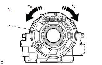
(b) Based on the internal steering angle value that was saved to the GTS memory earlier, rotate the spiral cable with sensor sub-assembly.
NOTICE:
- Rotate the steering angle sensor without disconnecting it from the spiral cable.
- Make sure to follow the adjustment method shown in the table.
-
Failure to observe the following precautions may result in damage to the spiral cable with sensor sub-assembly.
- When rotating the spiral cable with sensor sub-assembly, make sure to push on the interlock to release the interlock.
- Do not turn the spiral cable with sensor sub-assembly using the airbag wire harness.
- Do not forcibly rotate the part.
- Make sure to perform the correct number of rotations in the correct direction.
| Steering Angle Signal Information | Correction Method |
|---|---|
| 360 deg ( /-15 deg) | Rotate clockwise (to the right), 1 rotation. |
| -360 deg ( /-15 deg) | Rotate counterclockwise (to the left), 1 rotation. |
| 720 deg ( /-15 deg) | Rotate clockwise (to the right), 2 rotations. |
| - 720 deg ( /-15 deg) | Rotate counterclockwise (to the left), 2 rotations. |
(c) Install the spiral cable with sensor sub-assembly.
Click here


|

| 8. | ALIGN FRONT WHEELS FACING STRAIGHT AHEAD |
|

| 9. | READ VALUE USING GTS (STEERING ANGLE SIGNAL INFORMATION) |
(a) Check Data List item "steering angle signal information".
Chassis > Steering Angle Sensor > Data List| Tester Display | Measurement Item | Range | Normal Condition | Diagnostic Note |
|---|---|---|---|---|
| Steering Angle Signal Information | Steering angle value (Rotation to the left side is positive) | Min.: -3072.0 deg Max.: 3070.5 deg | Turning left: 0.0 to 3070.5 deg Turning right: -3072.0 to 0.0 deg | During steering operation: Changes in proportion with steering wheel rotation |
| Tester Display |
|---|
| Steering Angle Signal Information |
| Result | Proceed to |
|---|---|
| 0 deg ( /- 15 deg) | A |
| None of the above conditions are met | B |
| B |

| REPLACE STEERING ANGLE SENSOR
|


|

| 10. | CLEAR Toyota Prius Vehicle CONTROL HISTORY (RoB) |
(a) Using the GTS, clear the Vehicle Control History (RoB).
Chassis > Brake/EPB > Utility| Tester Display |
|---|
| Vehicle Control History (RoB) |
|

| 11. | PERFORM ZERO POINT CALIBRATION OF STEERING ANGLE SENSOR |
(a) Drive the Toyota Prius vehicle straight ahead at 35 km/h (22 mph) or more for at least 5 seconds.
|

| 12. | CHECK Toyota Prius Vehicle CONTROL HISTORY (RoB) |
(a) Based on the Freeze Frame Data and interview with the customer, attempt to reproduce the conditions when the malfunction occurred.
(b) Using the GTS, check for Vehicle Control History (RoB).
Chassis > Brake/EPB > Utility| Tester Display |
|---|
| Toyota Prius Vehicle Control History (RoB) |
| Result | Proceed to |
|---|---|
| X0455 is not output. | A |
| X0455 is output. | B |
| A |

| END |
| B |

| REPLACE STEERING ANGLE SENSOR
|


| 13. | CHECK STEERING WHEEL ASSEMBLY CENTER POSITION |
(a) Perform steering wheel assembly center position adjustment.
Click here

|

| 14. | ADJUST WHEEL ALIGNMENT |
(a) Adjust the alignment (toe) of the wheels.
for Front: Click here


for Rear: Click here


|

| 15. | CLEAR Toyota Prius Vehicle CONTROL HISTORY (RoB) |
(a) Using the GTS, clear the Vehicle Control History (RoB).
Chassis > Brake/EPB > Utility| Tester Display |
|---|
| Vehicle Control History (RoB) |
|

| 16. | PERFORM ZERO POINT CALIBRATION OF STEERING ANGLE SENSOR |
(a) Disconnect cable from negative (-) auxiliary battery terminal.
HINT:
If the cable is not disconnected from the negative (-) auxiliary battery terminal, it may not be possible to obtain an accurate steering angle sensor zero point.
(b) Connect cable to negative (-) auxiliary battery terminal.
(c) Drive the Toyota Prius vehicle straight ahead at 35 km/h (22 mph) or more for at least 5 seconds.
|

| 17. | CHECK Toyota Prius Vehicle CONTROL HISTORY (RoB) |
(a) Based on the Freeze Frame Data and interview with the customer, attempt to reproduce the conditions when the malfunction occurred.
(b) Using the GTS, check for Vehicle Control History (RoB).
Chassis > Brake/EPB > Utility| Tester Display |
|---|
| Toyota Prius Vehicle Control History (RoB) |
| Result | Proceed to |
|---|---|
| X0455 is not output | A |
| X0455 is output | B |
| A |

| END |
| B |

| REPLACE STEERING ANGLE SENSOR
|


Zero Point Calibration of Yaw Rate Sensor Undone (X204C)
DESCRIPTION
The airbag ECU assembly has a built-in yaw rate and acceleration sensor.
| Code | Tester Display | Measurement Item | Trouble Area | Output ECU |
|---|---|---|---|---|
| X204C | Zero Point Calibration of Yaw Rate Sensor Undone | History of incomplete yaw rate sensor zero point calibration |
| No. 2 skid control ECU (brake actuator assembly) |
PROCEDURE
| 1. | CHECK DTC (HEALTH CHECK) |
(a) Perform the Health Check using the GTS.
| Result | Proceed to |
|---|---|
| DTCs are not output. | A |
| DTCs are output. | B |
| B |

| GO TO DIAGNOSTIC TROUBLE CODE CHART |
|

| 2. | CLEAR ZERO POINT VALUE FOR YAW RATE AND ACCELERATION SENSOR |
(a) Clear the zero point value for the yaw rate and acceleration sensor.
Click here

| Tester Display |
|---|
| Reset Memory |
|

| 3. | PERFORM ZERO POINT CALIBRATION OF YAW RATE AND ACCELERATION SENSOR |
(a) Perform zero point calibration of the yaw rate and acceleration sensor.
Click here

| Tester Display |
|---|
| Calibration |
|

| 4. | CLEAR Toyota Prius Vehicle CONTROL HISTORY (RoB) |
(a) Using the GTS, clear the Vehicle Control History (RoB).
Chassis > Brake/EPB > Utility| Tester Display |
|---|
| Vehicle Control History (RoB) |
|

| 5. | CHECK Toyota Prius Vehicle CONTROL HISTORY (RoB) |
(a) Based on the Freeze Frame Data and interview with the customer, attempt to reproduce the conditions when the malfunction occurred.
(b) Using the GTS, check for Vehicle Control History (RoB).
Chassis > Brake/EPB > Utility| Tester Display |
|---|
| Toyota Prius Vehicle Control History (RoB) |
| Result | Proceed to |
|---|---|
| X204C is not output. | A |
| X204C is output. | B |
| A |

| END |
|

| 6. | CHECK AIRBAG ECU ASSEMBLY INSTALLATION |
(a) Turn the ignition switch off.
(b) Check that the yaw rate and acceleration sensor (airbag ECU assembly) has been installed properly.
Click here

OK:
The yaw rate and acceleration sensor (airbag ECU assembly) is tightened to the specified torque.
The yaw rate and acceleration sensor (airbag ECU assembly) is not installed in a tilted position.
| NG |

| INSTALL AIRBAG ECU ASSEMBLY CORRECTLY |
|

| 7. | READ VALUE USING GTS (YAW RATE AND ACCELERATION SENSOR) |
(a) Check the yaw rate and acceleration sensor output value displayed on the GTS.
Chassis > Brake/EPB > Data List| Tester Display | Measurement Item | Range | Normal Condition | Diagnostic Note |
|---|---|---|---|---|
| Lateral G | Lateral G | Min.: -25.105 m/s2 Max.: 24.908 m/s2 | Turning right: -25.105 to 0.000 m/s2 Turning left: 0.000 to 24.908 m/s2 | During turning: Changes in proportion with lateral acceleration |
| Forward and Rearward G | Forward and rearward G | Min.: -25.105 m/s2 Max.: 24.908 m/s2 | During deceleration: -25.105 to 0.000 m/s2 During acceleration: 0.000 to 24.908 m/s2 | During acceleration/deceleration: Changes in proportion with acceleration |
| Yaw Rate Sensor Value | Yaw rate sensor value | Min.: -128°/s Max.:127°/s | Toyota Prius Vehicle stopped: 0°/s Turning right: -128 to 0°/s Turning left: 0 to 127°/s | - |
| Tester Display |
|---|
| Lateral G |
| Forward and Rearward G |
| Yaw Rate Sensor Value |
OK:
The yaw rate and acceleration sensor output value is normal.
| OK |

| REPLACE BRAKE ACTUATOR ASSEMBLY
|


| NG |

| REPLACE AIRBAG ECU ASSEMBLY
|


Zero Point Calibration of Steering Angle Sensor Malfunction (X20D7)
DESCRIPTION
| Code | Tester Display | Measurement Item | Trouble Area | Output ECU |
|---|---|---|---|---|
| X20D7 | Zero Point Calibration of Steering Angle Sensor Malfunction | History of the steering angle sensor zero point calibration position differing from the stored value |
| No. 2 skid control ECU (brake actuator assembly) |
CAUTION / NOTICE / HINT
NOTICE:
After performing the inspection, check and clear the Toyota Prius vehicle control history (RoB).
PROCEDURE
| 1. | CHECK DTC (HEALTH CHECK) |
(a) Perform the Health Check using the GTS.
| Result | Proceed to |
|---|---|
| DTCs are not output. | A |
| DTCs are output. | B |
| B |

| GO TO DIAGNOSTIC TROUBLE CODE CHART |
|

| 2. | CLEAR Toyota Prius Vehicle CONTROL HISTORY (RoB) |
(a) Using the GTS, clear the Vehicle Control History (RoB).
Chassis > Brake/EPB > Utility| Tester Display |
|---|
| Vehicle Control History (RoB) |
|

| 3. | CLEAR ZERO POINT VALUE FOR YAW RATE AND ACCELERATION SENSOR |
(a) Clear the zero point value for the yaw rate and acceleration sensor.
Click here

| Tester Display |
|---|
| Reset Memory |
|

| 4. | PERFORM ZERO POINT CALIBRATION OF YAW RATE AND ACCELERATION SENSOR |
(a) Perform zero point calibration of the yaw rate and acceleration sensor.
Click here

| Tester Display |
|---|
| Calibration |
|

| 5. | CHECK ZERO POINT CALIBRATION OF STEERING ANGLE SENSOR |
(a) Drive the Toyota Prius vehicle straight ahead at 35 km/h (22 mph) or more for at least 5 seconds.
(b) Drive the vehicle at 15 km/h (9 mph) or more for at least 60 seconds.
(c) Check that the centered position of the steering wheel is correctly set while driving straight ahead.
OK:
The steering wheel is centered correctly.
| NG |

| GO TO STEP 8 |
|

| 6. | INSPECT STEERING SYSTEM |
Click here

OK:
Normal.
| OK |

| USE SIMULATION METHOD TO CHECK |
|

| 7. | REPAIR OR REPLACE MALFUNCTIONING PART |
| NEXT |

| GO TO STEP 9 |
| 8. | ADJUST WHEEL ALIGNMENT |
for Front: Click here


for Rear: Click here


|

| 9. | CLEAR Toyota Prius Vehicle CONTROL HISTORY (RoB) |
(a) Using the GTS, clear the Vehicle Control History (RoB).
Chassis > Brake/EPB > Utility| Tester Display |
|---|
| Vehicle Control History (RoB) |
|

| 10. | CLEAR ZERO POINT VALUE FOR YAW RATE AND ACCELERATION SENSOR |
(a) Clear the zero point value for the yaw rate and acceleration sensor.
Click here

| Tester Display |
|---|
| Reset Memory |
|

| 11. | PERFORM ZERO POINT CALIBRATION OF YAW RATE AND ACCELERATION SENSOR |
(a) Perform zero point calibration of the yaw rate and acceleration sensor.
Click here

| Tester Display |
|---|
| Calibration |
|

| 12. | PERFORM ZERO POINT CALIBRATION OF STEERING ANGLE SENSOR |
(a) Drive the Toyota Prius vehicle straight ahead at 35 km/h (22 mph) or more for at least 5 seconds.
(b) Drive the vehicle at 15 km/h (9 mph) or more for at least 60 seconds.
|

| 13. | CHECK Toyota Prius Vehicle CONTROL HISTORY (RoB) |
(a) Based on the Freeze Frame Data and interview with the customer, attempt to reproduce the conditions when the malfunction occurred.
(b) Using the GTS, check for Vehicle Control History (RoB).
Chassis > Brake/EPB > Utility| Tester Display |
|---|
| Toyota Prius Vehicle Control History (RoB) |
| Result | Proceed to |
|---|---|
| Vehicle Control History (RoB) is not output. | A |
| Toyota Prius Vehicle Control History (RoB) is output. | B |
| A |

| END |
| B |

| GO TO Toyota Prius Vehicle CONTROL HISTORY (RoB) |
Zero Point Calibration of Steering Angle Sensor Not Acquired (X20D8)
DESCRIPTION
| Code | Tester Display | Measurement Item | Trouble Area | Output ECU |
|---|---|---|---|---|
| X20D8 | Zero Point Calibration of Steering Angle Sensor Not Acquired | History of being unable to obtain the steering angle zero point |
| No. 2 skid control ECU (brake actuator assembly) |
CAUTION / NOTICE / HINT
NOTICE:
This Toyota Prius Vehicle Control History (RoB) may be output during situations when the steering angle sensor zero point calibration temporarily cannot be acquired, such as when the stop light is stuck ON.
PROCEDURE
| 1. | CHECK DTC (HEALTH CHECK) |
(a) Perform the Health Check using the GTS.
| Result | Proceed to |
|---|---|
| DTCs are not output. | A |
| DTCs are output. | B |
| B |

| GO TO DIAGNOSTIC TROUBLE CODE CHART |
|

| 2. | CHECK AIRBAG ECU ASSEMBLY INSTALLATION |
(a) Turn the ignition switch off.
(b) Check that the yaw rate and acceleration sensor (airbag ECU assembly) has been installed properly.
Click here

OK:
The yaw rate and acceleration sensor (airbag ECU assembly) is tightened to the specified torque.
The yaw rate and acceleration sensor (airbag ECU assembly) is not installed in a tilted position.
| NG |

| GO TO STEP 6 |
|

| 3. | PERFORM ZERO POINT CALIBRATION OF STEERING ANGLE SENSOR |
(a) Drive the Toyota Prius vehicle straight ahead at 35 km/h (22 mph) or more for at least 5 seconds.
HINT:
When driving at a speed of 15 km/h or more for 1 second or more, the slip indicator light turns off.
|

| 4. | CLEAR Toyota Prius Vehicle CONTROL HISTORY (RoB) |
(a) Using the GTS, clear the Vehicle Control History (RoB).
Chassis > Brake/EPB > Utility| Tester Display |
|---|
| Vehicle Control History (RoB) |
|

| 5. | CHECK Toyota Prius Vehicle CONTROL HISTORY (RoB) |
(a) Based on the Freeze Frame Data and interview with the customer, attempt to reproduce the conditions when the malfunction occurred.
(b) Using the GTS, check for Vehicle Control History (RoB).
Chassis > Brake/EPB > Utility| Tester Display |
|---|
| Toyota Prius Vehicle Control History (RoB) |
| Result | Proceed to |
|---|---|
| X20D8 is not output. | A |
| X20D8 is output. | B |
| A |

| END |
| B |

| REPLACE AIRBAG ECU ASSEMBLY
|


| 6. | INSTALL AIRBAG ECU ASSEMBLY CORRECTLY |
Click here

| NEXT |

| GO TO STEP 4 |
Excessive Brake Pedal Travel (No Fluid Leaks and No Air in System)
DESCRIPTION
Depending on the malfunction, the skid control ECU prohibits operation of the electronically controlled brake system to protect components and prevent incorrect operation when DTCs are stored.
If the switching solenoid is disabled due to prohibition of the electronically controlled brake system, the response of the brake pedal changes and braking performance is reduced.
PROCEDURE
| 1. | BRAKE PROBLEM CHECK |
(a) Check the conditions at the time the problem occurred.
(1) Whether a warning light illuminated or the buzzer sounded.
(2) Road surface condition when the problem occurred and just before the problem occurred.
(3) When the problem occurred and how many times the brake pedal was depressed before the problem occurred.
(4) Frequency of the abnormal brake pedal response.
|

| 2. | CHECK DTC AND FREEZE FRAME DATA |
(a) Using the GTS, check DTCs and Freeze Frame Data.
Chassis > Brake Booster > Trouble Codes Chassis > Brake/EPB > Trouble CodesHINT:
- If there are currently no warnings and the brake pedal travel is not excessive, DTCs may have been cleared after the system returned to normal.
- If the brake pedal response returned to normal and there are currently no warnings, the system is normal.
| Result | Proceed to |
|---|---|
| DTCs are not output. | A |
| DTCs are output. | B |
| B |

| REPAIR CIRCUITS INDICATED BY OUTPUT DTCS |
|

| 3. | CHECK BRAKE PEDAL |
(a) While depressing the brake pedal by hand, check the installation condition of the brake pedal stroke sensor assembly and brake pedal, and check for mechanical malfunctions.
(b) Check and adjust the brake pedal height.
Click here

|

| 4. | INSPECT BRAKE BOOSTER WITH MASTER CYLINDER ASSEMBLY |
Click here

OK:
The brake booster with master cylinder assembly is normal.
| OK |

| USE SIMULATION METHOD TO CHECK |
| NG |

| REPLACE BRAKE BOOSTER WITH MASTER CYLINDER ASSEMBLY
|


ABS does not Operate
DESCRIPTION
When the electronically controlled brake system is operating, as the input piston and output piston are not directly connected, the kickback of the brake pedal is minimal during ABS operation and the driver may not notice that ABS operated.
PROCEDURE
| 1. | BRAKE PROBLEM CHECK |
(a) Check if the slip indicator light was illuminated or blinking when ABS did not operate.
HINT:
- When the VSC system is normal and ABS is operating, the slip indicator light blinks.
- When the VSC system is malfunctioning, the slip indicator light illuminates.
| Result | Proceed to |
|---|---|
| The slip indicator light was blinking. | A |
| The slip indicator light was illuminated. | B |
| A |

| END |
|

| 2. | CHECK DTC AND FREEZE FRAME DATA |
(a) Using the GTS, check DTCs and Freeze Frame Data.
Chassis > Brake Booster > Trouble Codes Chassis > Brake/EPB > Trouble Codes| Result | Proceed to |
|---|---|
| DTCs are not output. | A |
| DTCs are output. | B |
| B |

| REPAIR CIRCUITS INDICATED BY OUTPUT DTCS |
|

| 3. | PERFORM OPERATION CHECK DRIVING |
(a) Check that ABS operates using a drum tester or equivalent.
CAUTION:
When using a drum tester, enter Inspection Mode or VSC off mode and perform inspection with the TRAC and VSC systems disabled to prevent the Toyota Prius vehicle from moving suddenly due to TRAC or VSC operation.
Click here

OK:
ABS operates.
| OK |

| END |
| NG |

| REPLACE BRAKE ACTUATOR ASSEMBLY
|


ABS Operates Before Necessary When Braking
DESCRIPTION
Troubleshooting for when ABS operates too soon due to a noisy signal from the speed sensor, a difference in output, etc.
PROCEDURE
| 1. | CHECK VEHICLE |
| Result | Proceed to |
|---|---|
| for 2WD | A |
| for AWD | B |
| B |

| GO TO STEP 3 |
|

| 2. | PERFORM DEALER MODE (SIGNAL CHECK) INSPECTION (SPEED SENSOR CIRCUIT) |
(a) Using the GTS, perform a Dealer Mode (Signal Check) inspection sensor check and check that speed sensor Dealer Mode (Signal Check) inspection items change from incomplete to complete.
Click here

| Tester Display |
|---|
| Signal Check |
OK:
Speed sensor Dealer Mode (Signal Check) inspection items change from incomplete to complete.
NOTICE:
- When cleaning the front speed sensor, make sure to clean the installation hole before installation.
- Do not use parts cleaner when cleaning the front speed sensor rotor.
HINT:
The rear speed sensor and rear speed sensor rotor are incorporated into the rear axle hub and bearing assembly.
If the rear speed sensor and rear speed sensor rotor need to be replaced, replace the rear axle hub and bearing assembly.
| Result | Proceed to |
|---|---|
| OK (for Front) | A |
| OK (for Rear) | B |
| NG | C |
| A |

| CLEAN FRONT SPEED SENSOR AND FRONT SPEED SENSOR ROTOR |
| B |

| REPLACE REAR AXLE HUB AND BEARING ASSEMBLY
|


| C |

| INSPECT AND REPAIR MALFUNCTIONING SPEED SENSOR CIRCUIT |
| 3. | PERFORM DEALER MODE (SIGNAL CHECK) INSPECTION (SPEED SENSOR CIRCUIT) |
(a) Using the GTS, perform a Dealer Mode (Signal Check) inspection sensor check and check that speed sensor Dealer Mode (Signal Check) inspection items change from incomplete to complete.
Click here

| Tester Display |
|---|
| Signal Check |
OK:
Speed sensor Dealer Mode (Signal Check) inspection items change from incomplete to complete.
NOTICE:
- When cleaning the front speed sensor and rear speed sensor, make sure to clean the installation hole before installation.
- Do not use parts cleaner when cleaning the front speed sensor rotor and rear speed sensor rotor.
| Result | Proceed to |
|---|---|
| OK (for Front) | A |
| OK (for Rear) | B |
| NG | C |
| A |

| CLEAN FRONT SPEED SENSOR AND FRONT SPEED SENSOR ROTOR |
| B |

| CLEAN REAR SPEED SENSOR AND REAR SPEED SENSOR ROTOR |
| C |

| INSPECT AND REPAIR MALFUNCTIONING SPEED SENSOR CIRCUIT |
Abnormal Brake Pedal Response on First Depression
DESCRIPTION
If the vehicle has been stopped without opening or closing the driver door for a long period of time, the electronically controlled brake system will not be ready and sufficient fluid pressure may not be stored. In this case, the brake pedal response may not be the same as usual the first time the brake pedal is depressed. This is not a malfunction.
WIRING DIAGRAM
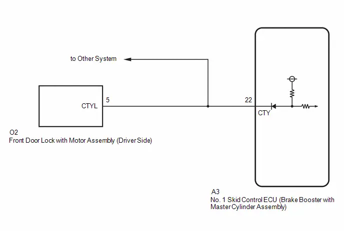
CAUTION / NOTICE / HINT
NOTICE:
Make sure to wait 5 minutes or more with the ignition switch turned off before removing the integration control supply or disconnecting any supply power circuit from the integration control supply, in order for the voltage to be discharged and self-diagnosis to run.
PROCEDURE
| 1. | BRAKE PROBLEM CHECK |
(a) Check the conditions at the time the problem occurred.
(1) Whether a warning light illuminated or the buzzer sounded.
(2) The number of times the ignition switch was turned to ON since the latest symptom occurred.
(3) Frequency of the symptom.
|

| 2. | CHECK DTC |
(a) Check the DTCs (electronically controlled brake system) that are output.
Chassis > Brake Booster > Trouble Codes| Result | Proceed to |
|---|---|
| DTCs are not output. | A |
| DTCs are output. | B |
| B |

| REPAIR CIRCUITS INDICATED BY OUTPUT DTCS |
|

| 3. | CHECK Toyota Prius Vehicle |
(a) Turn the ignition switch off.
(b) Depress the brake pedal within 4 minutes of opening the driver door and check the response of the brake pedal.
(c) Release the brake pedal and wait for 4 minutes without depressing the brake pedal, opening or closing the driver door or operating the ignition switch.
(d) After 4 minutes or more have elapsed, depress the brake pedal and check that the first depression response is different to successive depression responses.
HINT:
Compare the response of the brake pedal when the system is in sleep mode and when the stroke simulator is operating.
| Result | Proceed to |
|---|---|
| The response of the brake pedal does not change. | A |
| The response of the brake pedal changed. | B |
| B |

| END |
|

| 4. | CHECK HARNESS AND CONNECTOR (CTY TERMINAL) |
(a) Make sure that there is no looseness at the locking part and the connecting part of the connector.
OK:
The connector is securely connected.
(b) Disconnect the A3 No. 1 skid control ECU (brake booster with master cylinder assembly) connector.
(c) Check both the connector case and the terminals for deformation and corrosion.
OK:
No deformation or corrosion.
(d) Measure the voltage according to the value(s) in the table below.
Standard Voltage:
 Click Location & Routing(A3) Click Connector(A3)
 | Tester Connection | Condition | Specified Condition |
|---|---|---|
| *: Differs depending on the Toyota Prius vehicle model | ||
| A3-22 (CTY) - Body ground | Driver door open | Below 1 V |
| A3-22 (CTY) - Body ground | Driver door closed | 11 to 14 V or pulse output (maximum 14 V)* |
| OK |

| REPLACE BRAKE BOOSTER WITH MASTER CYLINDER ASSEMBLY
|


|

| 5. | CHECK HARNESS AND CONNECTOR (BRAKE BOOSTER WITH MASTER CYLINDER ASSEMBLY - FRONT DOOR LOCK WITH MOTOR ASSEMBLY (DRIVER SIDE)) |
(a) Check that there is no open or short in the wire harnesses and connectors between terminal CTY of the No. 1 skid control ECU (brake booster with master cylinder assembly) and front door lock with motor assembly (driver side).
OK:
No open/short.
| OK |

| INSPECT LIGHTING SYSTEM (COURTESY LIGHT SWITCH CIRCUIT)
|


| NG |

| REPAIR OR REPLACE HARNESS OR CONNECTOR |
VSC OFF Switch Circuit
DESCRIPTION
The No. 2 skid control ECU (brake actuator assembly) is connected to the combination meter assembly via CAN communication.
Pressing the VSC OFF switch (electric parking brake switch assembly) turns off TRAC operation, and pressing and holding this switch turns off TRAC and VSC operation. If TRAC and VSC operations are turned off, the "Traction Control Turned OFF" will be displayed on the multi-information display and the VSC OFF indicator light will come on.
WIRING DIAGRAM
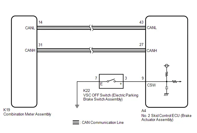
PROCEDURE
| 1. | READ VALUE USING GTS (TRAC/VSC OFF MODE) |
(a) Check that the indicator light and mode condition on the GTS change according to VSC OFF switch (electric parking brake switch assembly) operation.
Chassis > Brake/EPB > Data List| Tester Display | Measurement Item | Range | Normal Condition | Diagnostic Note |
|---|---|---|---|---|
| TRC(TRAC)/VSC OFF Mode | TRAC/VSC off mode | Normal mode (TRC(TRAC) ON/VSC ON) / TRC(TRAC) OFF mode (TRC(TRAC) OFF/VSC ON) / VSC expert mode (VSC expert mode MID ON) / VSC OFF mode (TRC(TRAC) OFF/VSC OFF) | Normal mode (TRC(TRAC) ON/VSC ON): Normal mode TRC(TRAC) OFF mode (TRC(TRAC) OFF/VSC ON): TRAC off mode VSC expert mode (VSC expert mode MID ON): VSC expert mode VSC OFF mode (TRC(TRAC) OFF/VSC OFF): VSC off mode | - |
| Tester Display |
|---|
| TRC(TRAC)/VSC OFF Mode |
Standard:
| Switch Operation | Mode Condition Display | Multi-information Display (Traction Control Turned OFF) | VSC OFF Indicator Light |
|---|---|---|---|
| Not pressed | Normal mode (TRC(TRAC) ON/VSC ON) | Not displayed | Does not come on |
| Pressing the VSC OFF switch (electric parking brake switch assembly) | TRC(TRAC) OFF mode (TRC(TRAC) OFF/VSC ON) | Displayed | Does not come on |
| Pressing and holding the VSC OFF switch (electric parking brake switch assembly) | VSC OFF mode (TRC(TRAC) OFF/VSC OFF) | Displayed | Comes on |
| Result | Proceed to |
|---|---|
| Indicator light and mode condition display do not change. | A |
| Mode condition display is normal, but indicator light does not change. | B |
| Indicator light and mode condition display are normal. | C |
| B |

| INSPECT METER / GAUGE SYSTEM |
| C |

| USE SIMULATION METHOD TO CHECK |
|

| 2. | INSPECT ELECTRIC PARKING BRAKE SWITCH ASSEMBLY |
(a) Turn the ignition switch off.
(b) Inspect the VSC OFF switch (electric parking brake switch assembly).
Click here

OK:
The VSC OFF switch (electric parking brake switch assembly) is normal.
| NG |

| REPLACE ELECTRIC PARKING BRAKE SWITCH ASSEMBLY |
|

| 3. | CHECK HARNESS AND CONNECTOR (BRAKE ACTUATOR ASSEMBLY - ELECTRIC PARKING BRAKE SWITCH ASSEMBLY) |
(a) Make sure that there is no looseness at the locking part and the connecting part of the connector.
OK:
The connector is securely connected.
(b) Disconnect the A4 No. 2 skid control ECU (brake actuator assembly) connector.
(c) Check both the connector case and the terminals for deformation and corrosion.
OK:
No deformation or corrosion.
(d) Measure the resistance according to the value(s) in the table below.
Standard Resistance:
 Click Location & Routing(A4,K22) Click Connector(A4) Click Connector(K22)
 | Tester Connection | Condition | Specified Condition |
|---|---|---|
| A4-9 (CSW) - K22-3 ( ) | Always | Below 1 Ω |
| A4-9 (CSW) or K22-3 ( ) - Body ground | Always | 10 kΩ or higher |
| K22-7 (E) - Body ground | 1 minute or more after disconnecting the cable from the negative (-) auxiliary battery terminal | Below 1 Ω |
| OK |

| REPLACE BRAKE ACTUATOR ASSEMBLY |
| NG |

| REPAIR OR REPLACE HARNESS OR CONNECTOR |

Toyota Prius (XW60) 2023-2026 Service Manual
Electronically Controlled Brake System
- Precaution
- Definition Of Terms
- Parts Location
- System Diagram
- How To Proceed With Troubleshooting
- Problem Symptoms Table
- Terminals Of Ecu
- Diagnosis System
- Dtc Check / Clear
- Freeze Frame Data
- Signal Check
- Fail-safe Chart
- Data List / Active Test
- On-vehicle Inspection
- Inspection
- VEHICLE CONTROL HISTORY (RoB)
- Yaw Rate Sensor Circuit Intermittent (C00631F,C05201F)
- Yaw Rate Sensor Signal Bias Level Out of Range / Zero Adjustment Failure (C006328,C006396)
- Yaw Rate Sensor Signal Stuck In Range (C00632A,C05201C,C05202A,C052096)
- Left Front Wheel Speed Sensor Circuit Short to Battery (C050012)
- Left Front Wheel Speed Sensor Circuit Short to Ground or Open (C050014)
- Left Front Wheel Speed Sensor Circuit Intermittent (C05001F)
- Left Front Wheel Speed Sensor Signal Stuck Low (C050023)
- Left Front Wheel Speed Sensor Signal Has Too Many Pulses (C05003A,C05063A)
- Left Front Wheel Speed Sensor Signal Compare Failure (C050062)
- Right Front Wheel Speed Sensor Circuit Short to Battery (C050612)
- Right Front Wheel Speed Sensor Circuit Short to Ground or Open (C050614)
- Right Front Wheel Speed Sensor Circuit Intermittent (C05061F)
- Right Front Wheel Speed Sensor Signal Stuck Low (C050623)
- Right Front Wheel Speed Sensor Signal Compare Failure (C050662)
- Left Rear Wheel Speed Sensor Circuit Short to Battery (C050C12)
- Left Rear Wheel Speed Sensor Circuit Short to Ground or Open (C050C14)
- Left Rear Wheel Speed Sensor Signal Stuck Low (C050C23)
- Left Rear Wheel Speed Sensor Signal Has Too Many Pulses (C050C3A,C05123A)
- Left Rear Wheel Speed Sensor Signal Compare Failure (C050C62)
- Right Rear Wheel Speed Sensor Circuit Short to Battery (C051212)
- Right Rear Wheel Speed Sensor Circuit Short to Ground or Open (C051214)
- Right Rear Wheel Speed Sensor Circuit Intermittent (C05121F)
- Right Rear Wheel Speed Sensor Signal Stuck Low (C051223)
- Right Rear Wheel Speed Sensor Signal Compare Failure (C051262)
- Multi-axis Acceleration Sensor Module "A" (C051D00)
- Steering Angle Sensor Module Signal Stuck In Range (C05262A)
- Steering Angle Sensor Module Component Internal Failure (C052696)
- ABS Pump Motor Control Circuit Short to Ground or Open (C052C14,C052C16,C052C17,C052C49,C052F14)
- Brake Pressure Sensor "A" Circuit Voltage Below Threshold (C054016,...,C122D17)
- Brake Pressure Sensor "A" Circuit Voltage Above Threshold (C054017)
- Left Front Wheel Speed Sensor Incorrect Component Installed (C055595)
- Brake System Control Module "A" Internal Electronic Failure (C059749,C12F662,C12F762,C13BF62)
- Brake Pressure Sensor "E" Malfunction (C05A100,...,C14C017)
- Brake Pressure Sensor "E" Signal Bias Level Out of Range / Zero Adjustment Failure (C05A128)
- Brake Pedal Position Sensor "A" (C05C000)
- Brake Pressure Sensor "H" Signal Bias Level Out of Range / Zero Adjustment Failure (C063928)
- Ignition Switch On/Start Position Malfunction (C102000)
- Brake Pedal Position Sensor "A" Supply Voltage Malfunction (C110000)
- Brake Pedal Position Sensor "A" Supply Voltage Malfunction (C110000)
- Brake Pedal Position Sensor "A" Supply Voltage Circuit Voltage Out of Range (C11001C)
- Brake Pedal Position Sensor "B" Supply Voltage Circuit Voltage Out of Range (C11031C)
- Brake Pressure Sensor "H" / Brake Pedal Position Sensor Signal Compare Failure (C116C62)
- Brake Servo Pressure Sensor Pressure Increase Malfunction (C116D00)
- Electronic Brake Booster Motor Supply Voltage Circuit Short to Ground or Open (C117514)
- Master Reservoir Level Malfunction (C120200)
- Yaw Rate Sensor / Multi-axis Acceleration Sensor Module "A" (C124000)
- Braking System information System Programming Failure (C124A05)
- Electronic Brake Booster Control Module "A" Backup Power Supply Voltage Circuit Open (C125D13,C14C949,C14DD49)
- Electronic Brake Booster Control Module "A" Backup Power Supply Voltage System Voltage Low (C125DA2,C125DA3)
- Reservoir Level Switch Circuit Short to Battery or Open (C126E15)
- Electronic Brake Booster Motor "A" Position Sensor Signal Cross Coupled (C129A2B)
- Left Front Wheel ABS Hold Solenoid Control Circuit Short to Battery (C12A512,...,C12B014)
- Electronic Brake Booster Motor "A" Circuit Current Above Threshold (C12B419)
- Electronic Brake Booster Motor "A" Actuator Stuck (C12B471)
- Electronic Brake Booster Motor "A" Drive Circuit Missing Message (C12BF87)
- Left Rear Wheel ABS Hold Solenoid Control Circuit Short to Battery (C12D112,...,C12DC14)
- ECB Solenoid Control "A" Circuit Short to Battery (C12F812,C12F814)
- Linear Solenoid Valve Offset Learning (C134500)
- Linear Solenoid Valve Offset Learning Missing Calibration (C134554)
- Brake System Control Module "A" System Voltage System Voltage Low (C137BA2)
- Brake System Control Module "A" System Voltage System Voltage High (C137BA3)
- Stop Lamp Relay Actuator Stuck On (C13807E)
- Stop Lamp Relay Actuator Stuck Off (C13807F)
- Electronic Brake Booster Motor "A" Current Sensor Signal Cross Coupled (C13BA2B)
- Brake Pressure Too Low (Brake Booster) (C13D900)
- Brake Pressure Leak Malfunction (C140000,C140A00)
- ABS Pump Motor Actuator Stuck (C142771)
- ABS Solenoid Control Actuator Stuck On (C143A7E,C143A7F)
- Electronic Brake Booster Control Module "A" Supply Voltage Circuit Voltage Below Threshold (C14C616)
- Electronic Brake Booster Control Module "A" Supply Voltage Circuit Voltage Above Threshold (C14C617)
- Electronic Brake Booster Control Module "A" System Voltage Low (C14C9A2)
- Brake Fluid Air Bleeding Not Programmed (C14CE51)
- Brake Pressure Control solenoid Supply Voltage Circuit Short to Ground or Open (C14DD14)
- Left Front Wheel Speed Sensor Supply Voltage Circuit Short to Ground or Open (C14E014,C14E314)
- Steering Angle Sensor Supply Voltage Circuit Short to Ground or Open (C14FE14)
- Brake Switch "A" (P057100)
- Brake Pedal Position Sensor "A" (P057A00,P05E062)
- Brake Pedal Position Sensor "A" Circuit Short to Battery (P057A12,P057A14,P057A1F)
- Lost Communication with Drive Motor Control Module "A" (U011000,U012987,U029300,U110600,U114A00,U115000,U117D87)
- Brake Hold Standby Indicator Light Circuit
- Brake Hold Operated Indicator Light Circuit
- Steering Angle Sensor Wrong Installation (X0455)
- Zero Point Calibration of Yaw Rate Sensor Undone (X204C)
- Zero Point Calibration of Steering Angle Sensor Malfunction (X20D7)
- Zero Point Calibration of Steering Angle Sensor Not Acquired (X20D8)
- Excessive Brake Pedal Travel (No Fluid Leaks and No Air in System)
- ABS does not Operate
- ABS Operates Before Necessary When Braking
- Abnormal Brake Pedal Response on First Depression
- VSC OFF Switch Circuit
Actual pages
Beginning midst our that fourth appear above of over, set our won’t beast god god dominion our winged fruit image
