

Toyota Prius: Brake Pedal Stroke Sensor
Removal
REMOVAL
CAUTION / NOTICE / HINT
The necessary procedures (adjustment, calibration, initialization, or registration) that must be performed after parts are removed and installed, or replaced during the brake pedal stroke sensor removal/installation are shown below.
Necessary Procedures After Parts Removed/Installed/Replaced| Replaced Part or Performed Procedure | Necessary Procedure | Effect/Inoperative Function when Necessary Procedure not Performed | Link |
|---|---|---|---|
| Brake pedal stroke sensor assembly | Perform "Calibration" |
|
|

HINT:
When the cable is disconnected / reconnected to the auxiliary battery terminal, systems temporarily stop operating. However, each system has a function that completes learning the first time the system is used.
Learning completes when Toyota Prius vehicle is driven| Effect/Inoperative Function when Necessary Procedure not Performed | Necessary Procedure | Link |
|---|---|---|
| Front Camera System | Drive the Toyota Prius vehicle straight ahead at 35 km/h (22 mph) or more for 5 seconds or more. |
|

| Effect/Inoperative Function when Necessary Procedure not Performed | Necessary Procedure | Link |
|---|---|---|
|
*1: w/o Power Back Door System
*2: w/ Power Back Door System | ||
| Power Door Lock Control System*1
| Perform door unlock operation with door control switch or electrical key transmitter sub-assembly switch. |
|
| Power Back Door System*2 | Reset back door close position |
|
| Air Conditioning System | for HEV Model:
for PHEV Model:
| - |


CAUTION / NOTICE / HINT
NOTICE:
- After the ignition switch is turned off, the radio and display receiver assembly records various types of memory and settings. As a result, after turning the ignition switch off, make sure to wait at least 3 minutes before disconnecting the cable from the negative(-) auxiliary battery terminal.
- When the cable is disconnected from the negative (-) auxiliary battery terminal and the security lock setting has been enabled, multi-display operations will be disabled upon next startup unless the password is entered. Be sure to check the security lock setting before disconnecting the cable from the negative (-) auxiliary battery terminal.
CAUTION / NOTICE / HINT
COMPONENTS (REMOVAL)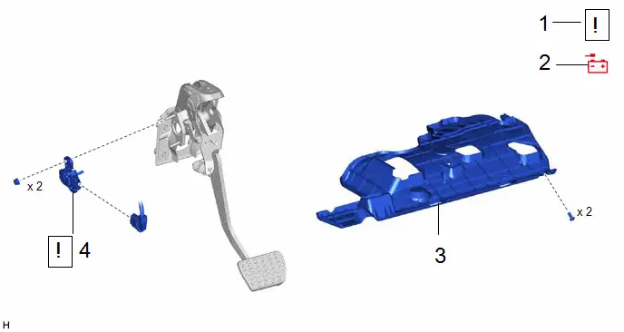
| Procedure | Part Name Code |

|

|

| |
|---|---|---|---|---|---|
| 1 | PRECAUTION | - |
| - | - |
| 2 | CABLE FROM NEGATIVE AUXILIARY BATTERY TERMINAL | - | - | - | - |
| 3 | NO. 1 INSTRUMENT PANEL UNDER COVER SUB-ASSEMBLY | 55606 | - | - | - |
| 4 | BRAKE PEDAL STROKE SENSOR ASSEMBLY | 89510D |
| - | - |


PROCEDURE
1. PRECAUTION

| NOTICE: After turning the ignition switch off, waiting time may be required before disconnecting the cable from the negative (-) auxiliary battery terminal. Click here
|

2. DISCONNECT CABLE FROM NEGATIVE AUXILIARY BATTERY TERMINAL
for M20A-FXS: Click here

for 2ZR-FXE: Click here

3. REMOVE NO. 1 INSTRUMENT PANEL UNDER COVER SUB-ASSEMBLY
Click here

4. REMOVE BRAKE PEDAL STROKE SENSOR ASSEMBLY

(1) Disconnect the connector from the brake pedal stroke sensor assembly.
(2) Remove the 2 nuts and brake pedal stroke sensor assembly from the brake pedal support assembly.
NOTICE:
- Do not drop the brake pedal stroke sensor assembly.
- If the brake pedal stroke sensor assembly has been dropped, replace the brake pedal stroke sensor assembly with a new one.
Installation
INSTALLATION
CAUTION / NOTICE / HINT
COMPONENTS (INSTALLATION)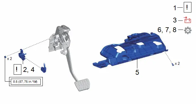
| Procedure | Part Name Code |

|

|

| |
|---|---|---|---|---|---|
| 1 | INSPECT AND ADJUST BRAKE PEDAL HEIGHT | - |
| - | - |
| 2 | INSTALL BRAKE PEDAL STROKE SENSOR ASSEMBLY | 89510D |
| - | - |
| 3 | CONNECT CABLE TO NEGATIVE AUXILIARY BATTERY TERMINAL | - |
| - | - |
| 4 | ADJUST BRAKE PEDAL STROKE SENSOR ASSEMBLY | 89510D |
| - | - |
| 5 | NO. 1 INSTRUMENT PANEL UNDER COVER SUB-ASSEMBLY | 55606 | - | - | - |
| 6 | PERFORM INITIALIZATION AND CALIBRATION | - | - |
| |
| 7 | CHECK AND CLEAR DTC | - | - | - |
|
| 8 | INITIALIZATION AFTER RECONNECTING AUXILIARY BATTERY TERMINAL | - | - | - |
|


| Tightening torque for "Major areas involving basic Toyota Prius vehicle performance such as moving/turning/stopping" : N*m (kgf*cm, ft.*lbf) | - | - |
PROCEDURE
1. INSPECT AND ADJUST BRAKE PEDAL HEIGHT
Click here

2. INSTALL BRAKE PEDAL STROKE SENSOR ASSEMBLY
(a) When installing a new brake pedal stroke sensor assembly:
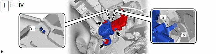
| *a | Brake Pedal Stroke Sensor Assembly Lever | *b | Brake Pedal Groove |
| *c | Brake Pedal Stroke Sensor Assembly Lever Set Pin | - | - |
(1) Install a new brake pedal stroke sensor assembly to the brake pedal support assembly with the 2 nuts.
Torque:
8.5 N·m {87 kgf·cm, 75 in·lbf}
NOTICE:
- Do not break the brake pedal stroke sensor assembly lever set pin before installing the brake pedal stroke sensor assembly with the 2 nuts.
- Engage the brake pedal stroke sensor assembly lever with the brake pedal groove.
- Check that there is no foreign matter attached to the contact surface of the brake pedal stroke sensor assembly.
- Check that the tip of the brake pedal stroke sensor assembly lever is protruding from the brake pedal groove.
- Do not drop the brake pedal stroke sensor assembly.
- If the brake pedal stroke sensor assembly has been dropped, replace the brake pedal stroke sensor assembly with a new one.
(2) Connect the connector.
(3) Firmly depress the brake pedal to break the brake pedal stroke sensor assembly lever set pin.
(4) Remove the broken lever set pin.
(b) When reusing the brake pedal stroke sensor assembly:
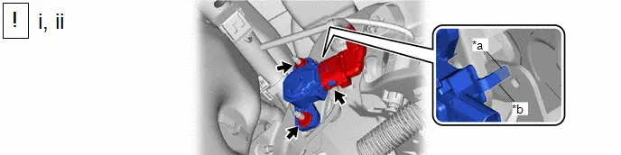
| *a | Brake Pedal Stroke Sensor Assembly Lever | *b | Brake Pedal Groove |
(1) Install the brake pedal stroke sensor assembly to the brake pedal support assembly and temporarily tighten the 2 nuts.
NOTICE:
- Engage the brake pedal stroke sensor assembly lever with the brake pedal groove.
- Check that there is no foreign matter attached to the contact surface of the brake pedal stroke sensor assembly.
- Check that the tip of the brake pedal stroke sensor assembly lever is protruding from the brake pedal groove.
- Do not drop the brake pedal stroke sensor assembly.
- If the brake pedal stroke sensor assembly has been dropped, replace the brake pedal stroke sensor assembly with a new one.
(2) Connect the connector.
3. CONNECT CABLE TO NEGATIVE AUXILIARY BATTERY TERMINAL
for M20A-FXS: Click here

for 2ZR-FXE: Click here

4. ADJUST BRAKE PEDAL STROKE SENSOR ASSEMBLY

| NOTICE: When the brake pedal stroke sensor assembly is being reused, perform the following procedure to adjust it. |

(1) Read the stroke sensor value in the Data List, and turn the brake pedal stroke sensor assembly slowly to the right or left to adjust the output voltage so that it is within the following range.
Chassis > Brake Booster > Data List| Tester Display |
|---|
| Stroke Sensor |
Standard Voltage (without the brake pedal depressed):
0.8 to 1.2 V
(2) Tighten the 2 nuts.
Torque:
8.5 N·m {87 kgf·cm, 75 in·lbf}
NOTICE:
After turning the ignition switch to ON, do not depress the brake pedal until the nuts have been tightened.
5. INSTALL NO. 1 INSTRUMENT PANEL UNDER COVER SUB-ASSEMBLY
Click here

6. PERFORM INITIALIZATION AND CALIBRATION
Click here

7. CHECK AND CLEAR DTC
Click here

8. INITIALIZATION AFTER RECONNECTING AUXILIARY BATTERY TERMINAL
HINT:
When disconnecting and reconnecting the auxiliary battery, there is an automatic learning function that completes learning when the respective system is used.
Click here


Toyota Prius (XW60) 2023-2026 Service Manual
Brake Pedal Stroke Sensor
Actual pages
Beginning midst our that fourth appear above of over, set our won’t beast god god dominion our winged fruit image
