

Toyota Prius: Electronic Shift Lever System
- Precaution
- Parts Location
- System Diagram
- How To Proceed With Troubleshooting
- Utility
- Problem Symptoms Table
- Terminals Of Ecu
- Freeze Frame Data
- Fail-safe Chart
- Data List / Active Test
- VEHICLE CONTROL HISTORY (RoB)
- Park/Neutral Switch Circuit Short to Ground (P085011,P085015)
- Gear Shift Control Module "A" System Internal Failure (P085D04)
- Gear Shift Control Module "A" Unexpected Operation (P085D94)
- Gear Lever Position Sensor Signal Compare Failure (P08A662)
- Gear Shift Position Circuit "A" Range/Performance Signal Cross Coupled (P09142B)
- Fail Safe Signal (Gear Shift Control Module "B" to "A") No Signal (P175231)
- Lost Communication with Gear Shift Control Module "B" (Local-CAN) Missing Message (P175387)
- Gear Shift Control Module "A" System Voltage Low (P1761A2)
- Sub Battery Module System Voltage Low (P1765A2)
- Gear Shift Control Module "A" A/D Processing Performance (P176900)
- IG2 Signal (Gear Shift Control Module "A") Circuit Short to Auxiliary Battery (P176D12)
- Gear Shift Control Module "B" System Voltage Low (P1771A2)
- Sub Battery Module (Gear Shift Control Module "B") System Voltage Low (P1775A2)
- Gear Shift Control Module Backup Power Supply Internal Electronic Failure (P177949)
- Lost Communication with Gear Shift Control Module Backup Power Supply Missing Message (P177A87)
- Lost Communication with Gear Shift Control Module "A" from "B" Missing Message (P178987)
- Gear Shift Control Module "B" Wake-up Circuit Short to Ground or Open (P178A14)
- Gear Shift Actuator "A" Supply Voltage "A" Circuit Short to Ground or Open (P179014)
- Gear Shift Actuator "A" Supply Voltage "B" Circuit Short to Ground or Open (P179314)
- Gear Shift Actuator "A" Control Circuit Internal Electronic Failure (P179C49)
- Gear Shift Actuator "A" Performance (P179E00)
- Gear Shift Control Module "A"/"B" IGCT Signal Compare Failure (P18A762)
- Gear Shift Control Module "A"/"B" IGCT-Scene Signal Compare Failure (P18A862)
- Gear Shift Control Module "B" EPBT Circuit Short to Battery (P18AF12)
- Gear Shift Control Module "B" Motor Angle Sensor "A" Performance (P18B200)
- Gear Shift Control Module "B" Motor Temperature Sensor "A" Circuit Voltage Out of Range (P18B31C)
- Gear Shift Actuator "A" Phase U-V-W Current Sensor Signal Compare Failure (P18B562)
- Gear Lever Position Sensor "A" Signal Plausibility Failure (P2E0064,P2E0464,P2E0864)
- Lost Communication with Body Control Module (Sub) Missing Message (U014000,...,U117000)
- Lost Communication with Gear Shift Control Module "B" (System 2) Missing Message (U029100)
- ECU Power Source Circuit
Precaution
PRECAUTION
PRECAUTIONS FOR DISCONNECTING AND RECONNECTING CABLE TO NEGATIVE (-) AUXILIARY BATTERY TERMINAL
NOTICE:
- After the ignition switch is turned off, there may be a waiting time
before disconnecting the negative (-) auxiliary battery terminal.
Click here

- When disconnecting and reconnecting the auxiliary battery
HINT:
When disconnecting and reconnecting the auxiliary battery, there is an automatic learning function that completes learning when the respective system is used.
Click here


PRECAUTION FOR INSPECTING ELECTRONIC SHIFT LEVER SYSTEM
(a) As the shift control ECU and shift actuator ECU do not immediately shutdown after the ignition switch is turned off, if the ignition switch is cycled within a short time, the ECUs may not shutdown. After turning the ignition switch off, wait approximately 1 minute or more for the shift control ECU and shift actuator ECU to completely shut down before connecting the GTS, opening/closing a door or operating a pedal.
(b) If the shift state cannot be changed from P, the auxiliary battery voltage may be low.
(c) If the electronic shift lever system has been damaged due to a flood, etc., the shift state will not be able to be changed to or from P. When the shift state cannot be changed from P to any other state, the parking lock is engaged. Therefore, make sure to release the parking lock manually before towing the Toyota Prius vehicle.
for PA10

for PB10, PB12


(d) If the electronic shift lever system is damaged, the ignition switch may not be able to be turned off with the ignition switch off operation. In this case, the ignition switch may be changed to off by operating the parking brake.
(e) Do not turn the ignition switch off when towing the Toyota Prius vehicle. Turning the ignition switch off may result in engagement of the parking lock which locks the drive wheels, resulting in a hazardous situation or accident.
(f) Check that the shift state is P and the parking brake is engaged before disconnecting the cable from the negative (-) auxiliary battery terminal.
(g) When removing or installing the shift control ECU or shift actuator ECU, make sure there is no power supplied*1 when disconnecting or connecting the connectors.
*1: Auxiliary battery, Bub-battery, Integrated capacitor, etc.
PRECAUTION WHEN REMOVING OR REPLACING SHIFT ACTUATOR ECU (SHIFT CONTROL ACTUATOR ASSSEMBLY)
(a) After any of the following procedures, it is necessary to perform initialization and learning for the shift actuator ECU.
Click here

- When removing and installing the shift actuator ECU (shift control actuator assembly).
- When replacing the shift actuator ECU (shift control actuator assembly).
NOTICE:
When initialization and learning has not been performed after replacing the shift actuator ECU, a malfunction such as the shift position not correctly changing, the shift position indicator not illuminating or displaying the incorrect drive state, etc. may occur.
(b) When any of the above procedures are completed, change the shift position to all positions and check the following items:
- The shift position indicator illuminates in accordance with the current position.
- The Toyota Prius vehicle does not move when in shift state P (parking brake is not engaged)
- The vehicle does not drive when in shift state N
- The vehicle drives when in shift state D or R
HINT:
After replacing the shift control ECU (transmission floor shift assembly), the function that automatically changes the shift state to P may not operate until the shift state has been changed to a drive state with the ignition switch ON (READY).
PRECAUTION WHEN REPLACING SHIFT CONTROL ECU (TRANSMISSION FLOOR SHIFT ASSEMBLY)
(a) After replacing the shift control ECU (transmission floor shift assembly), it is necessary to update the ECU security key.
Click here

(b) When any of the above procedures are completed, change the shift position to all positions and check the following items:
- The shift position indicator illuminates in accordance with the current position.
- The Toyota Prius vehicle does not move when in shift state P (parking brake is not engaged)
- The vehicle does not drive when in shift state N
- The vehicle drives when in shift state D or R
PRECAUTIONS WHEN REMOVING INTEGRATED CAPACITOR (INTEGRATION CONTROL SUPPLY)
(a) When disconnecting a wire harness of any component connected to the supply power of the integrated capacitor (integration control supply) or when removing the integrated capacitor (integration control supply), make sure to wait 5 minutes or more after turning the ignition switch off for self-diagnosis to complete and the voltage of the integrated capacitor (integration control supply) to discharge.
Parts Location
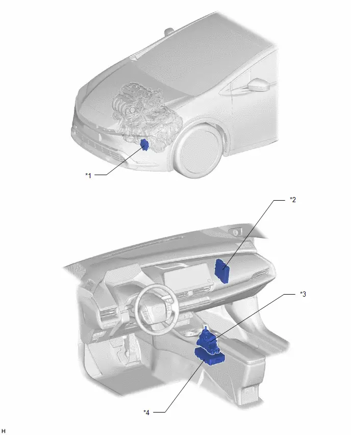
PARTS LOCATION
ILLUSTRATION
|
*1 |
SHIFT CONTROL ACTUATOR ASSEMBLY
|
*2 |
HYBRID Toyota Prius Vehicle CONTROL ECU |
|
*3 |
TRANSMISSION FLOOR SHIFT ASSEMBLY
|
*4 |
INTEGRATED CAPACITOR (INTEGRATION CONTROL SUPPLY) |
System Diagram
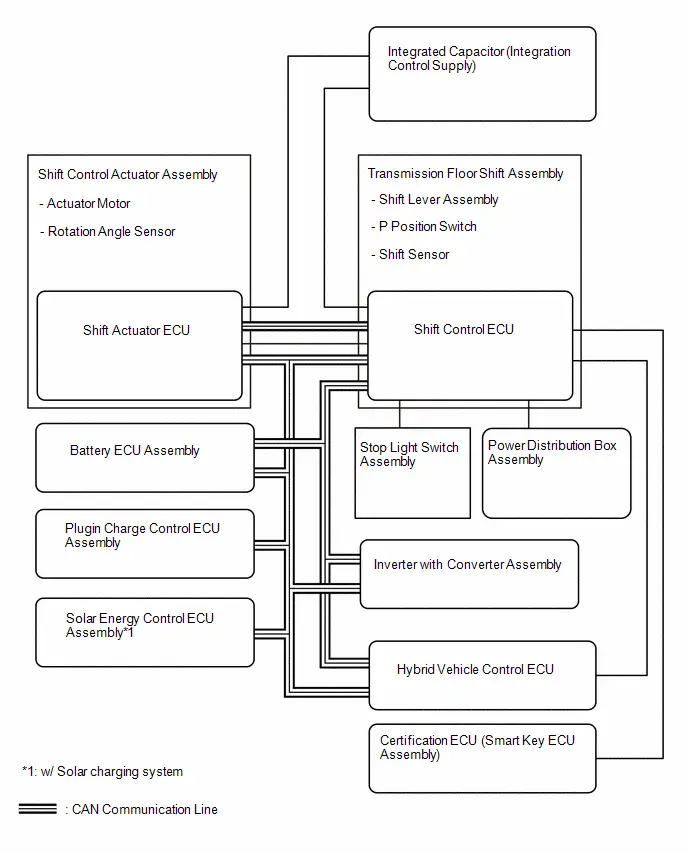
SYSTEM DIAGRAM
for HEV Model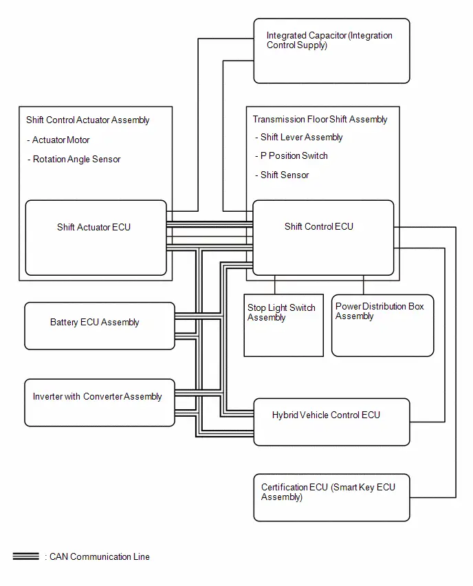 for PHEV Model
How To Proceed With Troubleshooting
CAUTION / NOTICE / HINT
HINT:
*: Use the GTS.
PROCEDURE
|
1. |
VEHICLE BROUGHT TO WORKSHOP |
|

|
2. |
CUSTOMER PROBLEM ANALYSIS |
|

|
3. |
CONNECT GTS TO THE DLC3* |
HINT:
If the display on the GTS indicates a communication error, inspect the DLC3.
|

|
4. |
CHECK DTC AND SAVE FREEZE FRAME DATA* |
(a) Check DTC
Powertrain > Hybrid Control > Trouble Codes(b) Check and save freeze frame data
Click here

HINT:
- Make sure to save freeze frame data because the data is necessary for simulation tests.
- If any CAN communication system DTCs are output, perform troubleshooting
for the CAN communication system first.
for HEV Model:

for PHEV Model:

|
Result |
Proceed to |
|---|---|
|
DTCs are output |
A |
|
DTCs are not output |
B |
| B |
 |
PROBLEM SYMPTOMS TABLE |
|

|
5. |
CLEAR DTC AND FREEZE FRAME DATA* |
|

|
6. |
CONDUCT VISUAL INSPECTION |
|

|
7. |
CONFIRM PROBLEM SYMPTOMS |
|
Result |
Proceed to |
|---|---|
|
Malfunction does not occur |
A |
|
Malfunction occurs |
B |
| B |
 |
GO TO STEP 10 |
|

|
8. |
DUPLICATE CONDITIONS THAT PRODUCE SYMPTOMS |
|

|
9. |
CHECK FOR DTC* |
|
Result |
Proceed to |
|---|---|
|
DTCs are not output |
A |
|
DTCs are output |
B |
| B |
 |
GO TO STEP 17 |
|

|
10. |
CONDUCT BASIC INSPECTION |
|
Result |
Proceed to |
|---|---|
|
Malfunctioning parts not confirmed |
A |
|
Malfunctioning parts confirmed |
B |
| B |
 |
GO TO STEP 18 |
|

|
11. |
CHECK ECU POWER SOURCE CIRCUIT |
|

|
12. |
CONFIRM CIRCUITS INDICATED BY OUTPUT DTCS |
|
Result |
Proceed to |
|---|---|
|
Malfunction not confirmed |
A |
|
Malfunction confirmed |
B |
| B |
 |
GO TO STEP 14 |
|

|
13. |
CHECK FOR INTERMITTENT PROBLEMS |
Click here

Click here

|

|
14. |
IDENTIFY PROBLEM |
|

|
15. |
ADJUST AND/OR REPAIR |
|

|
16. |
CONDUCT CONFIRMATION TEST |
| NEXT |
 |
END |
|
17. |
REFER TO DTC CHART |
Click here

| NEXT |
 |
GO TO STEP 12 |
|
18. |
CONDUCT PARTS INSPECTION |
| NEXT |
 |
GO TO STEP 14 |
Utility
UTILITY
ALL READINESS
HINT:
- With "All Readiness", you can use the GTS to check whether the DTC judgment has been completed.
- Perform the "All Readiness" check after simulating malfunction symptoms or when performing validation after finishing repairs.
(a) Clear the DTCs even if no DTCs are stored.
Powertrain > Hybrid Control > Clear DTCs(b) Turn the ignition switch off and wait for 1 minute or more without opening/closing a door or operating a pedal.
(c) Turn the ignition switch to ON.
(d) Perform the DTC confirmation driving pattern to run the DTC judgment.
Powertrain > Hybrid Control > Utility|
Tester Display |
|---|
|
All Readiness |
(e) Input the DTCs to be confirmed.
(f) Check the DTC judgment result.
|
GTS Display |
Description |
|---|---|
|
NORMAL |
|
|
ABNORMAL |
|
|
INCOMPLETE |
|
If the judgment result shows INCOMPLETE, perform the DTC confirmation driving pattern again.
(g) Turn the ignition switch off.
CHECK FOR DIAGNOSIS RELATED INFORMATION
(a) Check the diagnosis related information and freeze frame data, and then write them down.
Powertrain > Hybrid Control > Utility|
Tester Display |
|---|
|
Diagnosis Related Information |
HINT:
Clearing the DTCs will also clear the diagnosis related information.
CLEAR DIAGNOSIS RELATED INFORMATION
(a) Clear the diagnosis related information and freeze frame data.
Powertrain > Hybrid Control > Clear DTCsACT POSITION LEARNING
NOTICE:
- If the shift actuator ECU (shift control actuator assembly) is replaced
or removed, make sure to perform actuator position learning.
If not performed after replacing the ECU, a malfunction such as the shift position not correctly changing, the shift position indicator not illuminating or displaying the incorrect drive state, etc. may occur.
- When the shift actuator ECU (shift control actuator assembly) is replaced or removed, although the displayed value of Data List item "ACT Position Learning Complete Status" may be "Complete" based on information from before removal, make sure to perform actuator position learning.
(a) Turn the ignition switch to ON.
(b) Using the GTS, enter the following menus.
Powertrain > Hybrid Control > Utility|
Tester Display |
|---|
|
ACT Position Learning |
(c) According to the display on the GTS, perform ACT Position Learning.
(d) Using the GTS, enter the following menus.
Powertrain > Hybrid Control > Data List|
Tester Display |
|---|
|
ACT Position Learning Complete Status |
(e) Check that "Complete" is displayed.
HINT:
If a value other than "Complete" is displayed, check the part number and installation of the actuator and perform learning again.
(f) When any of the above procedures are completed, change the shift position to all positions and check the following items:
- The shift position indicator illuminates in accordance with the current position.
- The Toyota Prius vehicle does not move when in shift state P (parking brake is not engaged)
- The vehicle does not drive when in shift state N
- The vehicle drives when in shift state D or R
Problem Symptoms Table
PROBLEM SYMPTOMS TABLE
Electronic Shift Lever System|
Symptom |
Suspected Area |
Link |
|---|---|---|
|
Shift state does not change correctly or shift position indicator displays shift state other than actual |
Initialization and learning has not been performed after replacing the shift actuator ECU (shift control actuator assembly) |
|
|
Shift state cannot be changed from P to any other position |
The brake pedal is not depressed or is lightly depressed |
|
|
The brake pedal was depressed after the shift operation was performed |
||
|
The shift operation was performed at the same time the brake pedal was depressed |
||
|
Shift operation was performed when READY indicator light was blinking |
||
|
Shift state was changed to B |
||
|
Shift operation was performed when READY indicator light was not illuminated |
||
|
Shift operation was performed when accelerator pedal was depressed |
||
|
Auxiliary battery is discharged or voltage is low |
for M20A-FXS:
for 2ZR-FXE:
|
|
|
When stopped on an incline, a shift operation was performed with the READY indicator not illuminated |
|
|
|
When "Braking Power Low Stop in a Safe Place See Owner's Manual" is displayed on the multi-information display, despite depressing the brake pedal and moving the shift lever, "Press Brake to Shift" is displayed |
Release the brake pedal and depress it again, and then operate the shift lever. |
|
|
Shift state cannot change to P |
The P position switch was operated while driving |
|
|
The P position switch was operated when the READY indicator was flashing |
||
|
Auxiliary battery is discharged or voltage is low |
for M20A-FXS:
for 2ZR-FXE:
|
|
|
Inspect the ECU supply power |
|
|
|
Fail-safe is temporarily being performed |
|
|
|
The shift state changed to P unintentionally |
P position switch was operated unintentionally |
Be careful not to touch the P position switch unintentionally |
|
The ignition switch was turned off |
To change the shift state to other than P, turn the ignition switch to ON (IG) |
|
|
Fail-safe is temporarily being performed |
|
|
|
Attempt to exit the Toyota Prius vehicle with the shift state in other than P (driver door open, driver seat belt buckle OFF, brake OFF) |
|
|
|
Does not change to shift state B |
Shift state is being changed to B from a state other than D |
|
|
Auxiliary battery is discharged or voltage is low |
for M20A-FXS:
for 2ZR-FXE:
|
|
|
Does not change to shift state N |
The shift lever operation time was short |
Hold the shift lever in N for a certain amount of time |
|
The shift lever was not held in N long enough while stopped or driving at low speeds |
|
|
|
While performing a shift lever operation, the shift state changed to a state not intended |
After performing a shift operation, the shift lever was unintentionally pulled back to another position |
|
|
The shift state changed to N unintentionally |
The shift lever returned to the home position too slowly |
Check for objects hanging from the shift lever, modifications to the shift knob, foreign matter, etc. |
|
The shift lever was operated while driving or moved due to an object hanging from it |
|
|
|
The shift state was changed to D while reversing |
||
|
The P position switch was repeatedly pressed while driving |
||
|
The P position switch was unintentionally pressed and held while driving |
||
|
The shift state was changed to R while driving forward |
||
|
Auxiliary battery is discharged or voltage is low |
for M20A-FXS:
for 2ZR-FXE:
|
|
|
The shift state cannot be changed to D or R |
The shift lever returned to the home position too slowly |
Check for objects hanging from the shift lever, modifications to the shift knob, foreign matter, etc. |
|
The shift lever was not moved fully or operation time was too short |
Securely move the shift lever to each position. |
|
|
The READY indicator light not illuminated |
|
|
|
The shift state was changed to D while reversing |
||
|
The shift state was changed to R while driving forward |
||
|
Auxiliary battery is discharged or voltage is low |
for M20A-FXS:
for 2ZR-FXE:
|
|
|
The brake pedal is not depressed or is lightly depressed |
|
|
|
When the Toyota Prius vehicle was stopped in shift state N, the brake pedal was depressed after the shift operation was performed |
||
|
When the vehicle was stopped in shift state N, the shift operation was performed at the same time the brake pedal was depressed |
||
|
The shift lever was operated while the accelerator pedal was depressed |
||
|
When "Braking Power Low Stop in a Safe Place See Owner's Manual" is displayed on the multi-information display, despite depressing the brake pedal and moving the shift lever, "Press Brake to Shift" is displayed |
Release the brake pedal and depress it again, and then operate the shift lever. |
|
|
Supply power does not turn off (while the ignition switch is ON (IG)) |
When shift state is in N, the ignition switch was pushed within a certain amount of time of moving the shift lever to N |
|
|
The shift indicator does not illuminate or shift position indicator does not display the selected shift position |
Initialization and learning has not been performed after replacing the shift actuator ECU (shift control actuator assembly) |
|
|
Auxiliary battery is discharged or voltage is low |
for M20A-FXS:
for 2ZR-FXE:
|
|
|
Inspect the ECU supply power |
|
|
|
Shift indicator malfunction |
|
|
|
Electronic shift lever system warning message is displayed on the combination meter assembly |
Check for Toyota Prius vehicle control history (RoB) |
|
|
Auxiliary battery is discharged or voltage is low |
for M20A-FXS:
for 2ZR-FXE:
|
|
|
Inspect the ECU supply power |
|
|
|
Fail-safe is temporarily being performed |
|
|
|
Advanced park was interrupted or canceled |
Shift lever was moved while advanced park was operating |
|
|
P position switch was operated while advanced park was operating |


Terminals Of Ecu
TERMINALS OF ECU
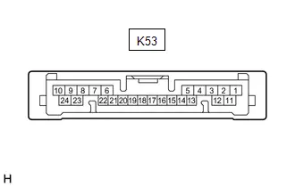
SHIFT CONTROL ECU (TRANSMISSION FLOOR SHIFT ASSEMBLY)
|
Terminal No. (Symbol) |
Terminal Description |
Condition |
Specified Condition |
|---|---|---|---|
|
K53-1 (IGP) - K53-9 (E1) |
Shift control ECU start signal |
Ignition switch ON |
11 to 14 V |
|
K53-2 (BATT) - K53-9 (E1) |
Auxiliary battery supply power (normal supply power) |
Always |
11 to 14 V |
|
K53-3 (IGCT) - K53-9 (E1) |
Shift control ECU start signal |
Ignition switch ON |
11 to 14 V |
|
K53-4 (BL) - K53-9 (E1) |
Back-up light relay operation signal |
Shift state R |
11 to 14 V |
|
shift state other than R |
Below 1 V |
||
|
K53-5 (WAKE) - K53-9 (E1) |
Shift actuator ECU start signal |
Ignition switch ON |
11 to 14 V |
|
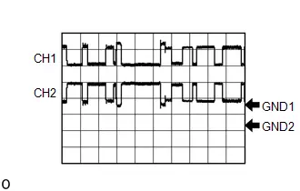
K53-6 (CA3L) - K53-9 (E1) |
CAN communication signal (Battery ECU local bus) |
Ignition switch ON |
Pulse generation (Waveform 1) |
|
K53-7 (PPOS) - K53-9 (E1) |
Shift state signal |
Ignition switch ON, shift state P |
Pulse generation (Waveform 2) |
|
K53-9 (E1) - Body ground |
Ground |
Always |
Below 1 Ω |
|
K53-10 (CA4L) - K53-9 (E1) |
CAN communication signal (SBW local bus) |
Ignition switch ON |
Pulse generation (Waveform 3) |
|
K53-11 (STP) - K53-9 (E1) |
Stop light switch signal |
Stop light switch ON (Brake pedal depressed) |
7 V or higher |
|
Stop light switch OFF (Brake pedal released) |
Below 2 V |
||
|
K53-13 (BUB) - K53-9 (E1) |
Integrated capacitor (integration control supply) power supply |
Ignition switch ON |
8 to 14 V |
|
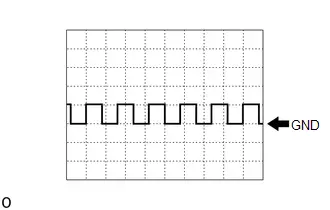
K53-14 (FS) - K53-9 (E1) |
Shift control actuator fail-safe signal |
Ignition switch ON |
Pulse generation (Waveform 4) |
|
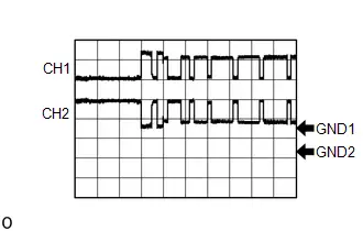
K53-15 (CA1H) - K53-9 (E1) |
CAN communication signal (Powertrain Bus) |
Ignition switch ON |
Pulse generation (Waveform 5) |
|
K53-16 (CA1L) - K53-9 (E1) |
CAN communication signal (Powertrain Bus) |
Ignition switch ON |
Pulse generation (Waveform 5) |
|
K53-17 (BUBI) - K53-9 (E1) |
Integrated capacitor (integration control supply) communication signal |
Ignition switch ON |
Pulse generation (Waveform 6) |
|
K53-19 (SBFS) - K53-9 (E1) |
Fail-safe signal |
Ignition switch ON |
Pulse generation (Waveform 7) |
|
K53-20 (BUBO) - K53-9 (E1) |
Integrated capacitor (integration control supply) communication signal |
Ignition switch ON |
Pulse generation (Waveform 8) |
|
K53-21 (CA3H) - K53-9 (E1) |
CAN communication signal (Battery ECU local bus) |
Ignition switch ON |
Pulse generation (Waveform 1) |
|
K53-23 (E12) - Body ground |
Ground |
Always |
Below 1 Ω |
|
K53-24 (CA4H) - K53-9 (E1) |
CAN communication signal (SBW local bus) |
Ignition switch ON |
Pulse generation (Waveform 3) |
HINT:
As the above standard values are based on the specified condition when the auxiliary battery voltage is between 11 and 14 V, the values may vary depending on the actual auxiliary battery condition.
(a) Oscilloscope waveforms
HINT:
Oscilloscope waveform samples are provided here for informational purposes. Noise and fluttering waveforms have been omitted.
(1) Waveform 1 (CAN communication signal)
|
Item |
Content |
|---|---|
|
Terminal |
CH1: K53-21 (CA3H) - K53-9 (E1) CH2: K53-6 (CA3L) - K53-9 (E1) |
|
Equipment Setting |
1 V/DIV., 10 μs/DIV. |
|
Condition |
Ignition switch ON |

HINT:
The waveform will vary depending on the content of the digital communication (digital signal).
(2) Waveform 2 (Shift state signal)
|
Item |
Content |
|---|---|
|
Terminal |
K53-7 (PPOS) - K53-9 (E1) |
|
Equipment Setting |
10 V/DIV., 10 ms/DIV. |
|
Condition |
Ignition switch ON, shift state P |
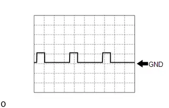
HINT:
The waveform differs depending on the shift state.
(3) Waveform 3 (CAN communication signal)
|
Item |
Content |
|---|---|
|
Terminal |
CH1: K53-24 (CA4H) - K53-9 (E1) CH2: K53-10 (CA4L) - K53-9 (E1) |
|
Equipment Setting |
1 V/DIV., 10 μs/DIV. |
|
Condition |
Ignition switch ON |
HINT:
The waveform will vary depending on the content of the digital communication (digital signal).
(4) Waveform 4 (Shift control actuator fail-safe signal)
|
Item |
Content |
|---|---|
|
Terminal |
K53-14 (FS) - K53-9 (E1) |
|
Equipment Setting |
10 V/DIV., 20ms/DIV. |
|
Condition |
Ignition switch ON |

HINT:
The waveform will differ when the shift control ECU is malfunctioning.
(5) Waveform 5 (CAN communication signal)
|
Item |
Content |
|---|---|
|
Terminal |
CH1: K53-15 (CA1H) - K53-9 (E1) CH2: K53-16 (CA1L) - K53-9 (E1) |
|
Equipment Setting |
1 V/DIV., 10 μs/DIV. |
|
Condition |
Ignition switch ON |
HINT:
The waveform will vary depending on the content of the digital communication (digital signal).
(6) Waveform 6 (Integrated capacitor (integration control supply) communication signal)
|
Item |
Content |
|---|---|
|
Terminal |
K53-17 (BUBI) - K53-9 (E1) |
|
Equipment Setting |
10 V/DIV., 10 ms/DIV. |
|
Condition |
Ignition switch ON |

HINT:
The duty ratio may differ depending on the communication contents of the integrated capacitor.
(7) Waveform 7 (Fail-safe signal)
|
Item |
Content |
|---|---|
|
Terminal |
K53-19 (SBFS) - K53-9 (E1) |
|
Equipment Setting |
10 V/DIV., 20ms/DIV. |
|
Condition |
Ignition switch ON |

HINT:
The waveform will differ when the shift control ECU is malfunctioning.
(8) Waveform 8 (Integrated capacitor (integration control supply) communication signal)
|
Item |
Content |
|---|---|
|
Terminal |
K53-20 (BUBO) - K53-9 (E1) |
|
Equipment Setting |
10 V/DIV., 10 ms/DIV. |
|
Condition |
Ignition switch ON |
HINT:
The duty ratio may differ depending on the communication contents of the integrated capacitor.
HINT:
As the shift actuator ECU (shift control actuator assembly) uses a waterproof connector, inspection of the resistance, voltage and waveform cannot be performed.
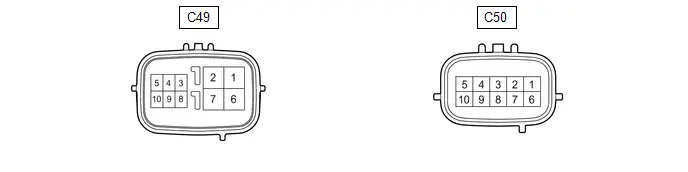
SHIFT ACTUATOR ECU (SHIFT CONTROL ACTUATOR ASSSEMBLY)
|
Terminal No. (Symbol) |
Terminal Description |
Condition |
Specified Condition |
|---|---|---|---|
|
C49-1 (MA1) - C49-2 (E01) |
Motor supply power (normal supply power) |
Always |
11 to 14 V |
|
C49-2 (E01) - Body ground |
Ground |
Always |
Below 1 Ω |
|
C49-3 (CA3L) - C49-2 (E01) |
CAN communication signal (Battery ECU local bus) |
Ignition switch ON |
Pulse generation (Waveform 1) |
|
C49-4 (CA3H) - C49-2 (E01) |
CAN communication signal (Battery ECU local bus) |
Ignition switch ON |
Pulse generation (Waveform 1) |
|
C49-5 (IGC1) - C49-2 (E01) |
Shift actuator ECU start signal |
Ignition switch ON |
11 to 14 V |
|
C49-6 (MA2) - C49-2 (E01) |
Motor supply power (integrated capacitor supply power) |
Ignition switch ON |
8 to 14 V |
|
C49-7 (E02) - Body ground |
Ground |
Always |
Below 1 Ω |
|
C49-8 (BUB1) - C49-2 (E01) |
Integrated capacitor (integration control supply) power supply |
Ignition switch ON |
8 to 14 V |
|
C50-3 (CA4L) - C49-2 (E01) |
CAN communication signal (SBW local bus) |
Ignition switch ON |
Pulse generation (Waveform 2) |
|
C50-4 (CA4H) - C49-2 (E01) |
CAN communication signal (SBW local bus) |
Ignition switch ON |
Pulse generation (Waveform 2) |
|
C50-5 (WAKE) - C49-2 (E01) |
Shift actuator ECU start signal |
Ignition switch ON |
11 to 14 V |
|
C50-6 (FS) - C49-2 (E01) |
Shift control actuator fail-safe signal |
Ignition switch ON |
Pulse generation (Waveform 3) |
|
C50-8 (BAT1) - C49-2 (E01) |
Auxiliary battery supply power (normal supply power) |
Always |
11 to 14 V |
HINT:
As the above standard values are based on the specified condition when the auxiliary battery voltage is between 11 and 14 V, the values may vary depending on the actual auxiliary battery condition.
(a) Oscilloscope waveforms
HINT:
Oscilloscope waveform samples are provided here for informational purposes. Noise and fluttering waveforms have been omitted.
(1) Waveform 1 (CAN communication signal)
|
Item |
Content |
|---|---|
|
Terminal |
CH1: C49-4 (CA3H) - C49-2 (E01) CH2: C49-3 (CA3L) - C49-2 (E01) |
|
Equipment Setting |
1 V/DIV., 10 μs/DIV. |
|
Condition |
Ignition switch ON |

HINT:
The waveform will vary depending on the content of the digital communication (digital signal).
(2) Waveform 2 (CAN communication signal)
|
Item |
Content |
|---|---|
|
Terminal |
CH1: C50-4 (CA4H) - C49-2 (E01) CH2: C50-3 (CA4L) - C49-2 (E01) |
|
Equipment Setting |
1 V/DIV., 10 μs/DIV. |
|
Condition |
Ignition switch ON |

HINT:
The waveform will vary depending on the content of the digital communication (digital signal).
(3) Waveform 3 (Shift control actuator fail-safe signal)
|
Item |
Content |
|---|---|
|
Terminal |
C50-6 (FS) - C49-2 (E01) |
|
Equipment Setting |
5 V/DIV., 20 ms/DIV. |
|
Condition |
Ignition switch ON |

HINT:
The waveform will differ when the shift actuator ECU is malfunctioning.
Freeze Frame Data
FREEZE FRAME DATA
CHECK FREEZE FRAME DATA
HINT:
The hybrid vehicle control ECU records vehicle and driving condition information as freeze frame data the moment a DTC is stored. Freeze frame data can help determine the vehicle conditions when the malfunction occurred and help duplicate conditions when troubleshooting.
(a) Select a DTC in order to display its freeze frame data.
Powertrain > Hybrid Control > Trouble CodesLIST OF FREEZE FRAME DATA
Powertrain > Hybrid Control|
Tester Display |
Measurement Item |
Range |
|---|---|---|
|
Toyota Prius Vehicle Speed |
Vehicle speed |
Min.: 0 km/h (0 mph), Max.: 255 km/h (158 mph) |
|
Accelerator Position |
Accelerator pedal depressed angle |
Min.: 0%, Max.: 127.5% |
|
Master Cylinder Control Torque |
Braking torque equivalent to master cylinder brake fluid pressure (Total braking torque) |
Min.: -4096.00 Nm, Max.: 4095.87 Nm |
|
Shift Position |
Current shift state |
P / R / N / D / B (S) |
|
Shift Position (Meter) |
Shift position on the meter |
Not Displayed / P / R / N / D / B (S) |
|
Ready Signal |
READY state is displayed |
ON / OFF |
|
HV/EV Activate Condition |
Startup state of the hybrid system |
Normal / Remote Air Control System / Remote |
|
Request Motor Regenerative Brake Torque |
Requested motor (MG2) regenerative braking torque |
Min.: -4096.00 Nm, Max.: 4095.87 Nm |
|
P Control Request Status |
Shift actuator ECU (shift control actuator assembly) operation request |
No Request / Lock(Normal) / Unlock(Normal) / Lock(Abnormal) / Unlock(Abnormal) / Unlock during Running(Normal) / Unlock during Running(Abnormal) |
|
P Control Status |
Shift state P status |
Control Duty Abnormal / Lock Position(Normal) / Lock Position(Abnormal) / Indefinite Position(Normal) / Indefinite Position(Abnormal) / Unlock Position(Normal) / Unlock Position(Abnormal) / Lock Position(Normal) / Lock Position(Abnormal) / Indefinite Position(Normal) / Indefinite Position(Abnormal) / Unlock Position(Normal) / Unlock Position(Abnormal) |
|
Abnormality Informing Status |
Malfunction notifications of other systems |
ON / OFF |
|
Meter Display Request (P Position Switch ON when Running) |
Notification from shift control displayed on the meter that the shift stated changed to N as a change to shift state P was attempted while driving |
ON or OFF |
|
Meter Display Request (Shift N Operation when Running) |
Notification from shift control displayed on the meter that the shift stated changed to N |
OFF, ON or Shift P Pressed for Extended Time/Repeatedly |
|
Meter Display Request (Shift Operation Rejection) |
Shift operation rejected message |
0 to 255 |
|
Identifying Signal of Shift R/D Operation during Ready OFF |
Identification indicating the shift state was changed to R or D with READY indicator not illuminated and the ignition switch ON |
ON / OFF |
|
P Position Automatic Change Request |
P position automatic change function request status |
ON / OFF |
|
Limiting Driving Force Request from Transmission Control System |
Drive torque limit request status of the HV system sent from the electronic shift lever system |
ON / OFF |
|
SP1 Toyota Prius Vehicle Speed |
Vehicle speed (SP1) |
Min.: 0 km/h (0 mph), Max.: 655.35 km/h (407.23 mph) |
|
Gear Shift Control Module Power Supply Voltage |
Shift control ECU power supply voltage |
Min.: -20.00 V, Max.: 19.84 V |
|
Gear Shift Control Module "B" CPU Temperature |
Shift actuator ECU internal temperature |
Min.: -50°C (-58°F), Max.: 205°C (401°F) |
|
IGCT Signal Status (Gear Shift Control Module) |
IGCT signal status of the shift control ECU |
ON / OFF |
|
IGCT Signal Status (Gear Shift Control Module "B") |
IGCT signal status of the shift actuator ECU |
ON / OFF |
|
IGP Signal Status (Gear Shift Control Module) |
IGP signal status of the shift control ECU |
ON / OFF |
|
IG Status (Gear Shift Control Module "B") |
IG status of the shift actuator ECU |
ON / OFF |
|
WAKE Signal Status (Gear Shift Control Module) |
WAKE signal status of the shift control ECU |
ON / OFF |
|
WAKE Signal Status (Gear Shift Control Module "B") |
WAKE signal status of the shift actuator ECU |
ON / OFF |
|
Backup Power Supply Type |
Backup supply power type |
Capacitor Type / Lithium Type / None |
|
Gear Shift Control Module Backup Signal Status |
System backup signal from the backup supply power |
Wake Up Request / Capacitor Internal Failure / Backup Mode (Low Capacity) / Backup Possible/Remote Charging Complete / Backup Impossible / Communication Stop / Backup Possible/Remote Charging Incomplete / Capacitor Internal Failure (Backup Possible) / Capacitor External Failure / Capacitor External Failure (Backup Possible) / Capacitor External Failure (Brake Factor) |
|
Gear Shift Control Module Backup Request |
System backup request from the backup supply power |
Wake Up/Sleep Permission / Interruption Permission (Not Remote) / ON (Not Remote) / OFF (Not Remote) / ON (Advanced Park) / OFF (Advanced Park) / ON (Stop&Start) |
|
Fail Safe Status (Gear Shift Control Module) |
Fail-safe status of the shift control ECU |
Unknown / OFF / ON |
|
Fail Safe Status (Gear Shift Control Module "B" to "A") |
Shift control ECU fail-safe status from the shift actuator ECU |
Normal / Abnormal / Unknown |
|
Fail Safe Power Supply Relay Connect Request |
Requested connection status of the shift actuator ECU motor drive relay (fail safe power supply) |
ON / OFF |
|
Shift Position (Current Position) |
Actual shift lever position (judged value) |
Home / R / N / D / B/M/S / Not Available |
|
Shift Sensor Status |
Shift sensor malfunction status |
Normal / Abnormal / Abnormal (Extreme) |
|
Shift Sensor 1 Status |
Shift lever sensor input signal status |
H / R / N / D / B/M/S / O / Abnormal / Unknown |
|
Shift Sensor 2 Status |
Shift lever sensor input signal status |
H / R / N / D / B/M/S / O / Abnormal / Unknown |
|
Shift Sensor 3 Status |
Shift lever sensor input signal status |
H / R / N / D / B/M/S / O / Abnormal / Unknown |
|
M or S Shift Position Indicator Turn On Request |
Shift position indicator (B) illumination status |
ON / OFF |
|
D Shift Position Indicator Turn On Request |
Shift position indicator (D) illumination status |
ON / OFF |
|
N Shift Position Indicator Turn On Request |
Shift position indicator (N) illumination status |
ON / OFF |
|
R Shift Position Indicator Turn On Request |
Shift position indicator (R) illumination status |
ON / OFF |
|
P Shift Position Indicator Turn On Request |
P position indicator illumination status |
ON / OFF |
|
Back Up Light Turn On Request |
Back-up light illumination command |
ON / OFF |
|
Stop Light Switch (Gear Shift Control Module) |
Stop light switch status |
ON / OFF |
|
P Position Switch Signal Status (Gear Shift Control Module) |
P position switch status |
ON / OFF |
|
Not P Position Learning Value (Output Side) |
Learned value (output axis) in accordance with the shift state other than P |
Min.: 0.0 deg, Max.: 124.5 deg |
|
Not P Position Learning Value (Motor Side) |
Learned value (calculated output axis angle based on the detected motor axis angle) in accordance with the shift state other than P |
Min.: 0.00 deg, Max.: 42949672.95 deg |
|
Absolute Angle Sensor Value 1 |
Value of axis sensor 1 (detected angle) |
Min.: 0.0 deg, Max.: 124.5 deg |
|
Absolute Angle Sensor Value 2 |
Value of axis sensor 2 (detected angle) |
Min.: 0.0 deg, Max.: 124.5 deg |
|
Gear Shift Actuator Power Supply Voltage (MA1) |
Voltage of gear shift motor supply power terminal (MA1) |
Min.: 0 V, Max.: 255 V |
|
Gear Shift Actuator Power Supply Voltage (MA2) |
Voltage of gear shift motor supply power terminal (MA2) |
Min.: 0 V, Max.: 255 V |
|
Gear Shift Actuator Motor Angle Sensor Value |
Value of motor axis sensor (detected angle) |
Min.: 0.00 deg, Max.: 358.59 deg |
|
Gear Shift Actuator Motor Speed |
Gear shift motor rotation speed |
Min.: 0.00 rpm deg, Max.: 10160.15 rpm |
|
Gear Shift Actuator Power Supply Relay Downstream Voltage |
Internal voltage of the actuator downstream of the motor supply power relay |
Min.: 0 V, Max.: 255 V |
|
U Phase Parking Lock Motor Current-Carrying Status (Gear Shift Control Module "B") |
Parking lock motor (U phase) drive signal |
ON / OFF |
|
V Phase Parking Lock Motor Current-Carrying Status (Gear Shift Control Module "B") |
Parking lock motor (V phase) drive signal |
ON / OFF |
|
W Phase Parking Lock Motor Current-Carrying Status (Gear Shift Control Module "B") |
Parking lock motor (W phase) drive signal |
ON / OFF |
|
U Phase Parking Lock Motor Terminal Current |
Current of the parking lock motor terminal (U phase) |
Min.: -64.0 A, Max.: 63.5 A |
|
V Phase Parking Lock Motor Terminal Current |
Current of the parking lock motor terminal (V phase) |
Min.: -64.0 A, Max.: 63.5 A |
|
W Phase Parking Lock Motor Terminal Current |
Current of the parking lock motor terminal (W phase) |
Min.: -64.0 A, Max.: 63.5 A |
|
ACT Relay Connect Status |
Connection status of drive relay of the shift actuator ECU motor |
ON / OFF |
|
ACT Relay Connect Request |
Requested connection status of drive relay of the shift actuator ECU motor |
ON / OFF |
|
ACT Position Status |
Status of the shift actuator ECU |
Other than P / None / Shift in P |
|
ACT Position Drive Request |
Operation request position of the shift actuator ECU |
Output NG / Shift in P / Other than P |
|
ACT Operation Status |
Operation status of the shift actuator ECU |
ON / OFF |
|
ACT Function Informing Status |
Function failure status of the shift actuator ECU |
Normal / Maintenance / Outside Judgment Guaranteed / Outside Operation Guaranteed / Outside Judgment/Operation Guaranteed / Operation NG / Operation NG/Outside Judgment Guaranteed |
|
ACT Monitoring Information |
Monitor status of the shift actuator ECU |
Normal / Driver Malfunction 1 / Driver Malfunction 2 / Driver Malfunction 3 / Driver Malfunction 4 / Driver Malfunction 5 / Driver Malfunction 6 / Sensor Malfunction 1 / Sensor Malfunction 2 / Sensor Malfunction 3 / Driver Malfunction 7 / Motor Malfunction 1 / Motor Malfunction 2 / Motor Malfunction 3 |
|
Shift Request during Advanced Drive/Park |
Shift request during advanced park operation |
OFF / ON (Gear Shift Control Module) / ON (Clearance Warning Control Module Semi-Auto) / ON (Clearance Warning Control Module Full-Auto) / ON (Advanced Drive Control Module) |
|
IGCT-Scene Signal Status (Gear Shift Control Module) |
IGCT-SCENE signal status of the shift control ECU |
ON / OFF |
|
IGCT-Scene Signal Status (Gear Shift Control Module "B") |
IGCT-SCENE signal status of the shift actuator ECU |
ON / OFF |
Fail-safe Chart
FAIL-SAFE CHART
If the shift control ECU detects a malfunction, a fail-safe function in the following table will be operated.
|
DTC No. |
Detection item |
Problem Symptoms |
Fail-safe Function |
|---|---|---|---|
|
P085011 |
Park/Neutral Switch Circuit Short to Ground |
The shift state cannot be changed to P by operating the P position switch |
- |
|
P085015 |
Park/Neutral Switch Circuit Short to Battery or Open |
The shift state cannot be changed to P by operating the P position switch |
- |
|
P085D04 |
Gear Shift Control Module "A" System Internal Failure |
Depending on the conditions, the shift state may not be able to be changed from P to a state other than P |
- |
|
P085D94 |
Gear Shift Control Module "A" Unexpected Operation |
|
- |
|
P08A662 |
Gear Lever Position Sensor Signal Compare Failure |
|
Shift state only permitted between P and N (however, shift state may not be able to be changed from P) |
|
P09142B |
Gear Shift Position Circuit "A" Range/Performance Signal Cross Coupled |
The following restrictions may occur:
|
The following fail-safe operations may occur:
|
|
P175231 |
Fail Safe Signal (Gear Shift Control Module "B" to "A") No Signal |
- |
- |
|
P175387 |
Lost Communication with Gear Shift Control Module "B" (Local-CAN) Missing Message |
- |
- |
|
P1761A2 |
Gear Shift Control Module "A" System Voltage Low |
- |
- |
|
P1765A2 |
Sub Battery Module System Voltage Low |
- |
- |
|
P176900 |
Gear Shift Control Module "A" A/D Processing Performance |
|
|
|
P176D12 |
IG2 Signal (Gear Shift Control Module "A") Circuit Short to Battery |
- |
- |
|
P1771A2 |
Gear Shift Control Module "B" System Voltage Low |
- |
- |
|
P1775A2 |
Sub Battery Module (Gear Shift Control Module "B") System Voltage Low |
- |
- |
|
P177949 |
Gear Shift Control Module Backup Power Supply Internal Electronic Failure |
- |
- |
|
P177996 |
Gear Shift Control Module Backup Power Supply Component Internal Failure |
- |
- |
|
P177A87 |
Lost Communication with Gear Shift Control Module Backup Power Supply Missing Message |
- |
- |
|
P178987 |
Lost Communication with Gear Shift Control Module "A" from "B" Missing Message |
- |
- |
|
P178A14 |
Gear Shift Control Module "B" Wake-up Circuit Short to Ground or Open |
- |
- |
|
P179014 |
Gear Shift Actuator "A" Supply Voltage "A" Circuit Short to Ground or Open |
|
|
|
P179314 |
Gear Shift Actuator "A" Supply Voltage "B" Circuit Short to Ground or Open |
- |
- |
|
P179C49 |
Gear Shift Actuator "A" Control Circuit Internal Electronic Failure |
The following restrictions may occur:
|
The following fail-safe operations may occur:
|
|
P179E00 |
Gear Shift Actuator "A" Performance |
|
|
|
P18A762 |
Gear Shift Control Module "A"/"B" IGCT Signal Compare Failure |
- |
- |
|
P18A862 |
Gear Shift Control Module "A"/"B" IGCT-Scene Signal Compare Failure |
- |
- |
|
P18AF12 |
Gear Shift Control Module "B" EPBT Circuit Short to Battery |
- |
- |
|
P18B200 |
Gear Shift Control Module "B" Motor Angle Sensor "A" Performance |
The following restrictions may occur:
|
The following fail-safe operations may occur:
|
|
P18B31C |
Gear Shift Control Module "B" Motor Temperature Sensor "A" Circuit Voltage Out of Range |
- |
- |
|
P18B562 |
Gear Shift Actuator "A" Phase U-V-W Current Sensor Signal Compare Failure |
|
|
|
P2E0064 |
Gear Lever Position Sensor "A" Signal Plausibility Failure |
|
Shift state only permitted between P and N (however, shift state may not be able to be changed from P) |
|
P2E0464 |
Gear Lever Position Sensor "B" Signal Plausibility Failure |
|
Shift state only permitted between P and N (however, shift state may not be able to be changed from P) |
|
P2E0864 |
Gear Lever Position Sensor "C" Signal Plausibility Failure |
|
Shift state only permitted between P and N (however, shift state may not be able to be changed from P) |
|
U014000 |
Lost Communication with Body Control Module (Sub) Missing Message |
- |
- |
|
U015586 |
Lost Communication with Instrument Panel Cluster (IPC) Control Module Signal (some circuit quantity, reported via serial data) Invalid |
|
- |
|
U029100 |
Lost Communication with Gear Shift Control Module "B" (System 2) Missing Message |
- |
- |
|
U029300 |
Lost Communication with Hybrid/EV Powertrain Control Module from Gear Shift Control Module "A" |
- |
- |
|
U110700 |
Lost Communication with Power Management Module (Gear Shift Control Module "A") |
P position automatic change function does not operate |
- |
|
U114F00 |
Lost Communication with Power Integration Module (System 2) Missing Message |
- |
- |
|
U117000 |
Lost Communication with Brake System Control Module (Gear Shift Control Module "A") |
Shift shock may occur when shift state changes from P to other state |
- |
Data List / Active Test
DATA LIST / ACTIVE TEST
DATA LIST
NOTICE:
- Some Data List values may vary significantly if there are slight differences in the environment in which the vehicle is operating when measurement is performed. Variations may also occur due to aging of the Toyota Prius vehicle. Due to these considerations, it is not always possible to provide definite values to be used for judgment of malfunctions. It is possible that a malfunction may be present even if measured values are within the "Normal Condition" range.
- In the event of a problem with intricate symptoms, collect sample data from another Toyota Prius vehicle of the same model operating under identical conditions in order to reach an overall judgment by comparing all the items in the Data List.
- In the table below, the values listed under "Normal Condition" are reference values. Do not depend solely on these reference values when deciding whether a part is faulty or not.
HINT:
Using the GTS to read the Data List allows the values or states of switches, sensors, actuators and other items to be read without removing any parts. This non-intrusive inspection can be very useful because intermittent conditions or signals may be discovered before parts or wiring is disturbed. Reading the Data List information early in troubleshooting is one way to save diagnostic time.
(a) According to the display on the GTS, read the Data List.
HINT:
When reading the Data List, first determine which items need to be monitored before proceeding. Attempting to view all of the data may result in a delayed, inaccurate inspection.
Powertrain > Hybrid Control > Data List|
Tester Display |
Measurement Item |
Range |
Normal Condition |
Diagnostic Note |
|---|---|---|---|---|
|
Toyota Prius Vehicle Speed |
Vehicle speed |
Min.: 0 km/h (0 mph), Max.: 255 km/h (158 mph) |
0 km/h (0 mph): Vehicle stopped No significant fluctuation: While driving at a constant speed |
- |
|
Accelerator Position |
Accelerator pedal depressed angle |
Min.: 0%, Max.: 127.5% |
0%: Accelerator pedal released 100%: Accelerator pedal fully depressed |
- |
|
Master Cylinder Control Torque |
Braking torque equivalent to master cylinder brake fluid pressure (Total braking torque) |
Min.: -4096.00 Nm, Max.: 4095.87 Nm |
Changes with the brake pedal pressure: Brake pedal depressed |
- |
|
Shift Position |
Current shift state |
P / R / N / D / B (S) |
The selected shift state is displayed |
- |
|
Shift Position (Meter) |
Shift position on the meter |
Not Displayed / P / R / N / D / B (S) |
The selected shift state is displayed |
- |
|
Ready Signal |
READY state is displayed |
ON / OFF |
ON: Ignition switch ON (READY) |
- |
|
HV/EV Activate Condition |
Startup state of the hybrid system |
Normal / Remote Air Control System / Remote |
Normal: Started by ignition switch Remote Air Control System: Started by remote air conditioning system Remote: Started by remote starter |
- |
|
Request Motor Regenerative Brake Torque |
Requested motor (MG2) regenerative braking torque |
Min.: -4096.00 Nm, Max.: 4095.87 Nm |
While braking: Varies depending on Toyota Prius vehicle operation conditions |
- |
|
Auxiliary Battery Voltage Low Times |
Auxiliary battery voltage low times |
Min: 0, Max: 255 |
- |
- |
|
P Control Request Status |
Shift actuator ECU (shift control actuator assembly) operation request |
No Request / Lock(Normal) / Unlock(Normal) / Lock(Abnormal) / Unlock(Abnormal) / Unlock during Running(Normal) / Unlock during Running(Abnormal) |
No Request: Ignition switch ON, no shift operation |
- |
|
P Control Status |
Shift state P status |
Control Duty Abnormal / Lock Position(Normal) / Lock Position(Abnormal) / Indefinite Position(Normal) / Indefinite Position(Abnormal) / Unlock Position(Normal) / Unlock Position(Abnormal) / Lock Position(Normal) / Lock Position(Abnormal) / Indefinite Position(Normal) / Indefinite Position(Abnormal) / Unlock Position(Normal) / Unlock Position(Abnormal) |
Lock Position(Normal): Ignition switch ON, no shift operation |
- |
|
Abnormality Informing Status |
Malfunction notifications of other systems |
ON / OFF |
ON: Malfunction occurring in this system OFF: Malfunction not occurring in this system |
- |
|
P Position Automatic Change Request |
P position automatic change function request status |
ON / OFF |
- |
- |
|
Limiting Driving Force Request from Transmission Control System |
Drive torque limit request status of the HV system sent from the electronic shift lever system |
ON / OFF |
OFF: Fail-safe control not being performed |
- |
|
SP1 Toyota Prius Vehicle Speed |
Vehicle speed (SP1) |
Min.: 0 km/h (0 mph), Max.: 655.35 km/h (407.23 mph) |
The same as actual vehicle speed |
- |
|
Gear Shift Control Module Power Supply Voltage |
Shift control ECU power supply voltage |
Min.: -20.00 V, Max.: 19.84 V |
8.00 to 15.40 V |
Displays terminal BATT voltage of the shift control ECU |
|
Gear Shift Control Module "B" CPU Temperature |
Shift actuator ECU internal temperature |
Min.: -50°C (-58°F), Max.: 205°C (401°F) |
0°C (32°F) to 205°C (401°F) |
- |
|
IGCT Signal Status (Gear Shift Control Module) |
IGCT signal status of the shift control ECU |
ON / OFF |
ON: Ignition switch ON |
Displays the ON/OFF value of terminal IGCT input signal |
|
IGCT Signal Status (Gear Shift Control Module "B") |
IGCT signal status of the shift actuator ECU |
ON / OFF |
ON: Ignition switch ON |
Displays the ON/OFF value of terminal IGC1 input signal |
|
IGP Signal Status (Gear Shift Control Module) |
IGP signal status of the shift control ECU |
ON / OFF |
ON: Ignition switch ON |
Displays the ON/OFF value of terminal IGP input signal |
|
IG Status (Gear Shift Control Module "B") |
IG status of the shift actuator ECU |
ON / OFF |
ON: Ignition switch ON |
- |
|
WAKE Signal Status (Gear Shift Control Module) |
WAKE signal status of the shift control ECU |
ON / OFF |
ON: WAKE signal ON OFF: WAKE signal OFF |
Displays the ON/OFF value of terminal WAKE output signal |
|
WAKE Signal Status (Gear Shift Control Module "B") |
WAKE signal status of the shift actuator ECU |
ON / OFF |
ON: WAKE signal ON OFF: WAKE signal OFF |
Displays the ON/OFF value of terminal WAKE input signal |
|
Backup Power Supply Type |
Backup supply power type |
Capacitor Type / Lithium Type / None |
- |
- |
|
Gear Shift Control Module Backup Signal Status |
System backup signal from the backup supply power |
Wake Up Request / Capacitor Internal Failure / Backup Mode (Low Capacity) / Backup Possible/Remote Charging Complete / Backup Impossible / Communication Stop / Backup Possible/Remote Charging Incomplete / Capacitor Internal Failure (Backup Possible) / Capacitor External Failure / Capacitor External Failure (Backup Possible) / Capacitor External Failure (Brake Factor) |
Normal: Backup Possible/Remote Charging Complete |
Displays the integrated capacitor status based on the waveform input to the BUBI terminal of the shift control ECU |
|
Gear Shift Control Module Backup Request |
System backup request from the backup supply power |
Wake Up/Sleep Permission / Interruption Permission (Not Remote) / ON (Not Remote) / OFF (Not Remote) / ON (Advanced Park) / OFF (Advanced Park) / ON (Stop&Start) |
- |
- |
|
Fail Safe Status (Gear Shift Control Module) |
Fail-safe status of the shift control ECU |
Unknown / OFF / ON |
- |
Hybrid Toyota Prius vehicle control ECU SBFS terminal |
|
Fail Safe Status (Gear Shift Control Module "B" to "A") |
Shift control ECU fail-safe status from the shift actuator ECU |
Normal / Abnormal / Unknown |
- |
Shift control ECU FS terminal |
|
Fail Safe Power Supply Relay Connect Request |
Requested connection status of the shift actuator ECU motor drive relay (fail safe power supply) |
ON / OFF |
OFF: Connection not requested ON: Connection requested |
- |
|
Shift Position (Current Position) |
Actual shift lever position (judged value) |
Home / R / N / D / B/M/S / Not Available |
Home: Shift lever in home position R: Shift lever in R N: Shift lever in N D: Shift lever in D B/M/S: Shift lever in B |
- |
|
Shift Sensor Status |
Shift sensor malfunction status |
Normal / Abnormal / Abnormal (Extreme) |
- |
- |
|
Shift Sensor 1 Status |
Shift lever sensor input signal status |
H / R / N / D / B/M/S / O / Abnormal / Unknown |
Home: Shift lever in home position R: Shift lever in R N: Shift lever in N D: Shift lever in D B/M/S: Shift lever in B O: Outside of range |
Shift sensor (type 1) |
|
Shift Sensor 2 Status |
Shift lever sensor input signal status |
H / R / N / D / B/M/S / O / Abnormal / Unknown |
Home: Shift lever in home position R: Shift lever in R N: Shift lever in N D: Shift lever in D B/M/S: Shift lever in B O: Outside of range |
Shift sensor (type 2) |
|
Shift Sensor 3 Status |
Shift lever sensor input signal status |
H / R / N / D / B/M/S / O / Abnormal / Unknown |
Home: Shift lever in home position R: Shift lever in R N: Shift lever in N D: Shift lever in D B/M/S: Shift lever in B O: Outside of range |
Shift sensor (type 3) |
|
M or S Shift Position Indicator Turn On Request |
Shift position indicator (B) illumination status |
ON / OFF |
ON: Shift state B OFF: Shift state not B |
- |
|
D Shift Position Indicator Turn On Request |
Shift position indicator (D) illumination status |
ON / OFF |
ON: Shift state drive (D) OFF: Shift state not drive (D) |
- |
|
N Shift Position Indicator Turn On Request |
Shift position indicator (N) illumination status |
ON / OFF |
ON: Shift state neutral (N) OFF: Shift state not neutral (N) |
- |
|
R Shift Position Indicator Turn On Request |
Shift position indicator (R) illumination status |
ON / OFF |
ON: Shift state reverse (R) OFF: Shift state not reverse (R) |
- |
|
P Shift Position Indicator Turn On Request |
P position indicator illumination status |
ON / OFF |
ON: Shift state park (P) OFF: Shift state not park (P) |
- |
|
Back Up Light Turn On Request |
Back-up light illumination command |
ON / OFF |
ON: Back-up light illuminated OFF: Back-up light not illuminated |
BL (terminal) output status |
|
Stop Light Switch (Gear Shift Control Module) |
Stop light switch status |
ON / OFF |
ON: Brake pedal depressed OFF: Brake pedal released |
- |
|
P Position Switch Signal Status (Gear Shift Control Module) |
P position switch status |
ON / OFF |
ON: P position switch pushed and held OFF: P position switch not pushed |
- |
|
Not P Position Learning Value (Output Side) |
Learned value (output axis) in accordance with the shift state other than P |
Min.: 0.0 deg, Max.: 124.5 deg |
21.8 to 35.8 deg |
- |
|
Not P Position Learning Value (Motor Side) |
Learned value (calculated output axis angle based on the detected motor axis angle) in accordance with the shift state other than P |
Min.: 0.00 deg, Max.: 42949672.95 deg |
50.20 to 64.60 deg |
- |
|
Absolute Angle Sensor Value 1 |
Value of axis sensor 1 (detected angle) |
Min.: 0.0 deg, Max.: 124.5 deg |
0.0 to 46.6 deg |
- |
|
Absolute Angle Sensor Value 2 |
Value of axis sensor 2 (detected angle) |
Min.: 0.0 deg, Max.: 124.5 deg |
0.0 to 46.6 deg |
- |
|
Gear Shift Actuator Power Supply Voltage (MA1) |
Voltage of gear shift motor supply power terminal (MA1) |
Min.: 0 V, Max.: 255 V |
8 to 15 V |
Displays the voltage input signal of shift control ECU terminal (MA1) |
|
Gear Shift Actuator Power Supply Voltage (MA2) |
Voltage of gear shift motor supply power terminal (MA2) |
Min.: 0 V, Max.: 255 V |
8 to 15 V: Ignition switch ON |
Displays the voltage input signal of shift control ECU terminal (MA2) |
|
Gear Shift Actuator Motor Angle Sensor Value |
Value of motor axis sensor (detected angle) |
Min.: 0.00 deg, Max.: 358.59 deg |
0.00 to 358.59 deg |
- |
|
Gear Shift Actuator Motor Speed |
Gear shift motor rotation speed |
Min.: 0.00 rpm deg, Max.: 10160.15 rpm |
0.00 to 10000.00 rpm |
- |
|
Gear Shift Actuator Power Supply Relay Downstream Voltage |
Internal voltage of the actuator downstream of the motor supply power relay |
Min.: 0 V, Max.: 255 V |
8 to 15 V: Ignition switch ON |
Internal voltage of shift control actuator |
|
U Phase Parking Lock Motor Current-Carrying Status (Gear Shift Control Module "B") |
Parking lock motor (U phase) drive signal |
ON / OFF |
ON: U phase energized OFF: U phase not energized |
- |
|
V Phase Parking Lock Motor Current-Carrying Status (Gear Shift Control Module "B") |
Parking lock motor (V phase) drive signal |
ON / OFF |
ON: V phase energized OFF: V phase not energized |
- |
|
W Phase Parking Lock Motor Current-Carrying Status (Gear Shift Control Module "B") |
Parking lock motor (W phase) drive signal |
ON / OFF |
ON: W phase energized OFF: W phase not energized |
- |
|
U Phase Parking Lock Motor Terminal Current |
Current of the parking lock motor terminal (U phase) |
Min.: -64.0 A, Max.: 63.5 A |
-62.5 to 62.5 A |
- |
|
V Phase Parking Lock Motor Terminal Current |
Current of the parking lock motor terminal (V phase) |
Min.: -64.0 A, Max.: 63.5 A |
-62.5 to 62.5 A |
- |
|
W Phase Parking Lock Motor Terminal Current |
Current of the parking lock motor terminal (W phase) |
Min.: -64.0 A, Max.: 63.5 A |
-62.5 to 62.5 A |
- |
|
ACT Relay Connect Status |
Connection status of drive relay of the shift actuator ECU motor |
ON / OFF |
OFF: Not connected ON: Connected |
- |
|
ACT Relay Connect Request |
Requested connection status of drive relay of the shift actuator ECU motor |
ON / OFF |
OFF: Connection not requested ON: Connection requested |
- |
|
ACT Position Status |
Status of the shift actuator ECU |
Other than P / None / Shift in P |
Shift in P: Shift state P Other than P: Shift state not P None: Other than above |
- |
|
ACT Position Drive Request |
Operation request position of the shift actuator ECU |
Output NG / Shift in P / Other than P |
Shift in P: P position request Other than P: Not P position Output NG: Not requested |
- |
|
ACT Operation Status |
Operation status of the shift actuator ECU |
ON / OFF |
OFF: Shift actuator ECU stopped ON: Shift actuator ECU changing |
- |
|
ACT Function Informing Status |
Function failure status of the shift actuator ECU |
Normal / Maintenance / Outside Judgment Guaranteed / Outside Operation Guaranteed / Outside Judgment/Operation Guaranteed / Operation NG / Operation NG/Outside Judgment Guaranteed |
Normal: Normal condition Other than above: Malfunctioning |
- |
|
ACT Monitoring Information |
Monitor status of the shift actuator ECU |
Normal / Driver Malfunction 1 / Driver Malfunction 2 / Driver Malfunction 3 / Driver Malfunction 4 / Driver Malfunction 5 / Driver Malfunction 6 / Sensor Malfunction 1 / Sensor Malfunction 2 / Sensor Malfunction 3 / Driver Malfunction 7 / Motor Malfunction 1 / Motor Malfunction 2 / Motor Malfunction 3 |
Normal: Normal condition Other than above: Malfunctioning |
- |
|
ACT Position Learning Complete Status |
Learning complete status of the shift actuator ECU |
Incomplete / Running / Abort / Complete |
Incomplete: Before learning Running: Learning in progress Abort: Learning failed Complete: Learning complete / normal |
When the shift actuator ECU (shift control actuator assembly) has been removed, perform initialization and learning and confirm that they complete successfully. |
|
Shift Request during Advanced Drive/Park |
Shift request during advanced park operation |
OFF / ON (Gear Shift Control Module) / ON (Clearance Warning Control Module Semi-Auto) / ON (Clearance Warning Control Module Full-Auto) / ON (Advanced Drive Control Module) |
OFF: No shift request ON (Gear Shift Control Module): Is shift request |
- |
|
IGCT-Scene Signal Status (Gear Shift Control Module) |
IGCT-SCENE signal status of the shift control ECU |
ON / OFF |
ON: Ignition switch ON |
Displays the ON/OFF value of terminal IGCT or IGS input signal |
|
IGCT-Scene Signal Status (Gear Shift Control Module "B") |
IGCT-SCENE signal status of the shift actuator ECU |
ON / OFF |
ON: Ignition switch ON |
Displays the ON/OFF value of terminal IGC1 or IGS1 input signal |
|
Shift P Operation during Running Trigger Counter |
Number of times P switch was pressed while Toyota Prius vehicle being driven |
Min: 0, Max: 255 |
- |
- |
|
Shift P Operation before Vehicle Stop Trigger Counter |
Number of times shift state was not changed to P when P position switch was operated before Toyota Prius vehicle stopped |
Min: 0, Max: 255 |
- |
- |
|
Shift P Operation during Other than Shift P Operation Trigger Counter |
Number of times the P position switch was operated when the shift lever was not in the home position |
Min: 0, Max: 255 |
- |
- |
|
Auto Change to Shift Position P Cancel Trigger Counter |
Number of times P position automatic change function did not operate |
Min: 0, Max: 255 |
- |
- |
|
Voltage Low for Shift Control System Trigger Counter |
Number of times shift control system did not operate due to low voltage |
Min: 0, Max: 255 |
- |
- |
|
Shift Operation when Auxiliary Battery Voltage Low Trigger Counter |
Number of times a shift operation was performed while auxiliary battery voltage was low |
Min: 0, Max: 255 |
- |
- |
|
Consecutive Shift Change between Shift P and Other than Shift P in Short Times Trigger Counter |
Number of times shift state was attempted to be changed between P and other than P within a short period of time |
Min: 0, Max: 255 |
- |
- |
|
Shift Operation during Ready Indicator Blinking Trigger Counter |
Number of times shift state was attempted to be changed from P with READY indicator light blinking |
Min: 0, Max: 255 |
- |
- |
|
Shift R/D/B(S) Operation during Ready OFF Trigger Counter |
Number of times shift state was attempted to be changed to R, D or B with READY indicator not illuminated |
Min: 0, Max: 255 |
- |
- |
|
Shift Operation without Depressing Brake from Shift Position P Trigger Counter |
Number of times shift state was attempted to be changed from P with brake pedal not depressed |
Min: 0, Max: 255 |
- |
- |
|
Shift Operation during Accelerator & Brake Depress Trigger Counter |
Number of times shift state was attempted to be changed from P with READY indicator light illuminated and accelerator and brake pedals depressed |
Min: 0, Max: 255 |
- |
- |
|
Shift B(S) Operation from Shift Position P/N Trigger Counter |
Number of times shift state was attempted to be changed from P or N to B |
Min: 0, Max: 255 |
- |
- |
|
Shift B(S) Operation from Shift Position R Trigger Counter |
Number of times shift state was attempted to be changed from R to B |
Min: 0, Max: 255 |
- |
- |
|
Shift D Operation during Backward Movement Trigger Counter |
Number of times shift state was attempted to be changed to D while reversing |
Min: 0, Max: 255 |
- |
- |
|
Shift R Operation during Forward Movement Trigger Counter |
Number of times shift state was attempted to be changed to R while driving forward |
Min: 0, Max: 255 |
- |
- |
|
Shift R/D Operation during Ready OFF Trigger Counter |
Number of times shift state was attempted to be changed to R, D or B with READY indicator not illuminated and the ignition switch ON |
Min: 0, Max: 255 |
- |
- |
|
Shift N Operation during Running Trigger Counter |
Number of times shift state was changed to N by holding shift lever in N for a certain amount of time while driving |
Min: 0, Max: 255 |
- |
- |
|
Quick Shift Operation to Shift Position N during Running Trigger Counter |
Number of times shift state was changed to N when shift lever not held in N while driving |
Min: 0, Max: 255 |
- |
- |
|
Shift N Change by Busy Shift Trigger Counter |
Number of times shift state was changed to neutral (N) by moving the shift lever to R, D and/or N repeatedly within short period of time |
Min: 0, Max: 255 |
- |
- |
|
Shift N Operation on The Way Back to Home Position after Shift D/R Operation Trigger Counter |
Number of times shift state was changed to N when shift lever was returning from R or D |
Min: 0, Max: 255 |
- |
- |
|
Shift R Operation on The Way Back to Home Position after Shift D Operation Trigger Counter |
Number of times shift state was changed to D when shift lever was returning from R |
Min: 0, Max: 255 |
- |
- |
|
Shift D Operation on The Way Back to Home Position after Shift R Operation Trigger Counter |
Number of times shift state was changed to R when shift lever was returning from D |
Min: 0, Max: 255 |
- |
- |
|
Shift N Operation at Short Times during Low Speed/Stopping Trigger Counter |
Number of times shift state was attempted to be changed to N without holding shift lever in N for a long enough time when driving at low speed or stopped |
Min: 0, Max: 255 |
- |
- |
|
Shift P Repeated Operation Trigger Counter during Running |
Number of times shift state changed to N as P position switch was consecutively operated while driving |
Min: 0, Max: 255 |
- |
- |
|
Shift P Hold Down Trigger Counter during Running |
Number of times shift state changed to N as P position switch was pressed and held while driving |
Min: 0, Max: 255 |
- |
- |
|
Shift P Operation when Auxiliary Battery Low Voltage Trigger Counter |
Number of times that the P position switch was operated during battery power failure |
Min: 0, Max: 255 |
- |
- |
|
Auto Change to Shift Position P when Driver Get Out Trigger Counter |
Number of times shift state changed to P automatically due to driver exiting Toyota Prius vehicle |
Min: 0, Max: 255 |
- |
- |
|
Shift Position N Hold Mode ON during IG OFF/ACC ON Trigger Counter |
Number of times the ignition switch was turned off with the shift state N |
Min: 0, Max: 255 |
- |
- |
|
Shift Operation on Gradient during Ready OFF Trigger Counter |
Number of times a shift operation was performed while on an incline with the ignition switch ON, not in READY mode |
Min: 0, Max: 255 |
- |
- |
|
Shift Operation during Advanced Drive/Park Trigger Counter |
Number of times a shift operation was performed while advanced drive or advanced park was operating |
Min: 0, Max: 255 |
- |
- |
|
Shift P Operation during Advanced Drive/Park Trigger Counter |
Number of times the P position switch was operated while advanced drive or advanced park was operating |
Min: 0, Max: 255 |
- |
- |
|
Shift Operation during Release Shift P Restriction Request Trigger Counter |
Number of times shift state was attempted to be changed from P during P release prohibit request |
Min: 0, Max: 255 |
- |
- |
|
Shift D/R Operation Rejection from Shift Position N without Depressing Brake Pedal Trigger Counter |
Number of times shift state was attempted to be changed from N to drive state with brake pedal not depressed |
Min: 0, Max: 255 |
- |
- |
|
Shift D/R Operation Rejection from Shift Position N during Accelerator Pedal Depress Trigger Counter |
Number of times shift state was attempted to be changed from N to drive state with accelerator pedal depressed |
Min: 0, Max: 255 |
- |
- |
VEHICLE CONTROL HISTORY (RoB)
VEHICLE CONTROL HISTORY (RoB)
CHECK THE VEHICLE CONTROL HISTORY (HYBRID CONTROL)
HINT:
- The vehicle control history data (Hybrid control) stores the history of the reject function and system protection operations.
- The number of occurrences, date and distance are stored in batches for each item.
(a) Toyota Prius Vehicle Control History:
Powertrain > Hybrid Control > Utility|
Tester Display |
|---|
|
Vehicle Control History (RoB) |
NOTICE:
When several Toyota Prius vehicle control histories are stored, prioritize performing the required actions for "Voltage Low for Shift Control System".
|
Code |
Tester Display |
Measurement Item |
Diagnostic Note |
|---|---|---|---|
|
X0500 |
Shift P Operation during Running |
History of P position switch operation while driving |
Operate the P position switch after the Toyota Prius vehicle has stopped |
|
X0501 |
Shift Operation when Auxiliary Battery Voltage Low |
History of shift position change attempted when auxiliary battery voltage was low |
Replace or recharge the auxiliary battery |
|
X0502 |
Consecutive Shift Change between Shift P and Other than Shift P in Short Times |
History of shift state being attempted to be changed to and from P within a short period of time |
Wait for a while and then attempt to change the shift state again, or try again after turning the ignition switch to ON (READY) |
|
X0503 |
Shift Operation during Ready Indicator Blinking |
History of attempt to change shift state from P with READY indicator light flashing |
Perform a shift operation after the READY indicator light illuminates |
|
X0504 |
Shift R/D/B(S) Operation during Ready OFF |
History of attempt to change shift state to R, D or B with ignition switch ON and READY indicator not illuminated |
Perform a shift operation with the READY indicator light illuminated |
|
X0505 |
Shift Operation during Accelerator & Brake Depress |
History of attempts to change shift state from P with READY indicator light illuminated and accelerator and brake pedals depressed |
Perform the shift operation while depressing only the brake pedal and not the accelerator pedal |
|
X0506 |
Shift B(S) Operation from Shift Position R |
History of shift state being changed to N when attempting to change to B directly from R |
Change to shift state D first, and then to B |
|
X0507 |
Shift D Operation during Backward Movement |
History of attempt to change shift state to D while reversing |
Change the shift state to D after the Toyota Prius vehicle has stopped |
|
X0508 |
Shift R Operation during Forward Movement |
History of attempt to change shift state to R while driving forward |
Change the shift state to R after the Toyota Prius vehicle has stopped |
|
X050A |
Quick Shift Operation to Shift Position N during Running |
History of shift state being changed to N while driving, without shift lever being held in N for a long enough time |
- |
|
X050B |
Shift N Change by Busy Shift |
History of shift state being changed to N due to shift lever being repeatedly moved to R, D and/or N within a short period of time |
Wait for a while and then attempt to change the shift state again |
|
X050C |
Shift N Operation on The Way Back to Home Position after Shift D/R Operation |
History of shift state being changed to N when shift lever was returning from R or D |
|
|
X050D |
Shift R Operation on The Way Back to Home Position after Shift D Operation |
History of shift state being changed to R when shift lever was returning from D |
Remove hand from shift lever after performing a shift operation |
|
X050E |
Shift D Operation on The Way Back to Home Position after Shift R Operation |
History of shift state being changed to D when shift lever was returning from R |
Remove hand from shift lever after performing a shift operation |
|
X0510 |
Shift Operation without Depressing Brake from Shift Position P |
|
Perform a shift operation while firmly depressing the brake pedal |
|
X0511 |
Shift N Operation at Short Times during Low Speed/Stopping |
History of attempt to change shift state to N by not holding shift lever in N for a long enough time while stopped or driving at a low speed |
Hold the shift lever in N for a certain amount of time |
|
X0512 |
Shift B(S) Operation from Shift Position P/N |
History of attempt to change shift state from P or N to B |
Change to shift state D first, and then to B |
|
X0513 |
Shift N Operation during Running |
History of shift state being changed to N by holding shift lever in N for a certain amount of time while driving |
|
|
X0515 |
Shift P Operation before Toyota Prius Vehicle Stop |
History of shift state not being changed to P when P position switch was operated before vehicle was stopped |
Operate the P position switch after the vehicle has stopped |
|
X0517 |
Auto Change to Shift Position P Cancel |
History of P position automatic change function not operating |
Operate the P position switch, confirm that the shift indicator has changed to P, then turn the ignition switch from ON (IG) to off again |
|
X051A |
Shift Operation on Gradient during Ready OFF |
History of attempt to change shift state from P with ignition switch ON (IG) and READY indicator light off while on an incline |
Perform a shift operation from the READY ON state |
|
X051B |
Shift Operation during Advanced Drive/Park |
History of shift lever operation while advanced park was operating |
Be careful not to unintentionally touch the shift lever |
|
X051C |
Shift P Operation during Advanced Drive/Park |
History of P position switch operation while advanced park was operating |
Be careful not to unintentionally touch the P position switch |
|
X051D |
Auto Change to Shift Position P when Driver Get Out |
History of door opened with the driver seatbelt unfastened and brake pedal not depressed while shift state is other than P |
|
|
X051E |
Shift Position N Hold Mode ON during IG OFF/ACC ON |
History of ignition switch being turned off with the shift state N after a shift operation was performed |
Operate the P position switch, then turn the ignition switch off after the shift state has changed to P |
|
X0554 |
Shift P Repeated Operation during Running |
History of P position switch being operated repeatedly while driving |
Be careful not to touch the P position switch unintentionally |
|
X0555 |
Shift P Hold Down during Running |
History of P position switch being pressed and held while driving |
Be careful not to touch the P position switch unintentionally |
|
X0559 |
Shift P Operation when Auxiliary Battery Low Voltage |
History of attempt to change shift state to P with auxiliary battery depleted |
Recharge or replace the auxiliary battery |
|
X057B |
Shift Operation during Release Shift P Prohibition Request |
History of attempt to change shift state from park P to other shift state with Toyota Prius vehicle not in a driving mode |
Be careful not to unintentionally touch the shift lever |
|
X057D |
Shift D/R Operation Rejection from Shift Position N without Depressing Brake Pedal |
History of attempt to change shift state from N to D or R with brake pedal not depressed |
Perform the shift operation while depressing only the brake pedal and not the accelerator pedal |
|
X057E |
Shift D/R Operation Rejection from Shift Position N during Accelerator Pedal Depress |
History of attempt to change shift state from N to D or R with accelerator pedal depressed |
Perform the shift operation while depressing only the brake pedal and not the accelerator pedal |
|
XF01E |
ECU Security Key Not Registered (Gear Shift Control Module) |
Update of the ECU security key stored in the shift control ECU has not been performed |
Make sure to perform Update ECU Security Key after replacing the shift control ECU (transmission floor shift assembly)
|

CLEAR THE Toyota Prius Vehicle CONTROL HISTORY (ELECTRONIC SHIFT LEVER SYSTEM)
Powertrain > Hybrid Control > Utility|
Tester Display |
|---|
|
Vehicle Control History (RoB) |
NOTICE:
By performing this procedure, all stored Toyota Prius Vehicle Control History items will be cleared.
VEHICLE CONTROL HISTORY FREEZE FRAME DATA (ELECTRONIC SHIFT LEVER SYSTEM)
(a) Select a vehicle control history item to access the applicable freeze frame data.
(b) Check the freeze frame Data recorded with the Vehicle Control History.
VEHICLE CONTROL HISTORY FREEZE FRAME DATA|
GTS Display |
Description |
|---|---|
|
Total Distance Traveled |
Drive total distance |
|
Total Distance Traveled - Unit |
Drive total distance unit |
Toyota Prius Vehicle CONTROL HISTORY (AIRBAG SYSTEM)
HINT:
A part of the control history can be confirmed using the vehicle control history.
Click here

Park/Neutral Switch Circuit Short to Ground (P085011,P085015)
DESCRIPTION
The P position switch and shift control ECU are built into the transmission floor shift assembly. The shift control ECU judges operation of the P position switch.
|
DTC No. |
Detection Item |
DTC Detection Condition |
Trouble Area |
MIL |
Warning Indicate |
DTC Output from |
Priority |
Note |
|---|---|---|---|---|---|---|---|---|
|
P085011 |
Park/Neutral Switch Circuit Short to Ground |
When the ignition switch is ON and the auxiliary battery voltage is a certain value or more, it is detected that the P position switch is stuck low (1 trip detection logic) |
Shift control ECU (transmission floor shift assembly) |
Does not come on |
Multi-information Display Error Message
|
Hybrid Control |
A |
SAE: P0851 |
|
P085015 |
Park/Neutral Switch Circuit Short to Auxiliary Battery or Open |
When the ignition switch is ON and the auxiliary battery voltage is a certain value or more, it is detected that the P position switch is stuck high (1 trip detection logic) |
Shift control ECU (transmission floor shift assembly) |
Does not come on |
Multi-information Display Error Message
|
Hybrid Control |
A |
SAE: P0852 |
CONFIRMATION DRIVING PATTERN
HINT:
After repair has been completed, clear the DTC and then check that the Toyota Prius vehicle has returned to normal by performing the All Readiness check procedure.
Click here

- With the brake pedal depressed, perform a shift operation then change the shift state to N.
- Press the P position switch to change the shift state to P.
CAUTION / NOTICE / HINT
NOTICE:
- When removing or installing the shift control ECU or shift actuator
ECU, make sure there is no power supplied*1 when disconnecting or connecting
the connectors.
*1: Auxiliary battery, sub-battery, integrated capacitor, etc.
- When disconnecting a wire harness of any component connected to the supply power of the integrated capacitor or when removing the integrated capacitor, make sure to wait 5 minutes or more after turning the ignition switch off for self-diagnosis to complete and the voltage of the integrated capacitor to discharge.
- Before performing troubleshooting, check the fuses, connector connections and contact pressure of the relevant terminals for this circuit.
PROCEDURE
|
1. |
REPLACE SHIFT CONTROL ECU (TRANSMISSION FLOOR SHIFT ASSEMBLY) |
HINT:
Click here

| NEXT |
 |
COMPLETED |
Gear Shift Control Module "A" System Internal Failure (P085D04)
DESCRIPTION
The shift control ECU is built into the shift lock control unit assembly. The shift control ECU monitors the ECU internal operation, and detects internal malfunctions (data flash malfunction).
|
DTC No. |
Detection Item |
DTC Detection Condition |
Trouble Area |
MIL |
Warning Indicate |
DTC Output from |
Priority |
Note |
|---|---|---|---|---|---|---|---|---|
|
P085D04 |
Gear Shift Control Module "A" System Internal Failure |
When the auxiliary battery voltage is certain value or more, a shift control ECU internal malfunction (data flash malfunction) is repeatedly detected (1 trip detection logic) |
Shift control ECU (transmission floor shift assembly) |
Does not come on |
Multi-information Display Error Message
|
Hybrid Control |
A |
SAE: P085D |
CONFIRMATION DRIVING PATTERN
HINT:
After repair has been completed, clear the DTC and then check that the Toyota Prius vehicle has returned to normal by performing the All Readiness check procedure.
Click here

- Turn the ignition switch to ON and wait for 1 minute or more.
CAUTION / NOTICE / HINT
NOTICE:
- When removing or installing the shift control ECU or shift actuator
ECU, make sure there is no power supplied*1 when disconnecting or connecting
the connectors.
*1: Auxiliary battery, sub-battery, integrated capacitor, etc.
- When disconnecting a wire harness of any component connected to the supply power of the integrated capacitor or when removing the integrated capacitor, make sure to wait 5 minutes or more after turning the ignition switch off for self-diagnosis to complete and the voltage of the integrated capacitor to discharge.
- Before performing troubleshooting, check the fuses, connector connections and contact pressure of the relevant terminals for this circuit.
PROCEDURE
|
1. |
REPLACE SHIFT CONTROL ECU (TRANSMISSION FLOOR SHIFT ASSEMBLY) |
HINT:
Click here

| NEXT |
 |
COMPLETED |
Gear Shift Control Module "A" Unexpected Operation (P085D94)
DESCRIPTION
The shift control ECU monitors the ECU internal operation, and if a malfunction is detected, the hybrid vehicle control ECU stores a DTC.
|
DTC No. |
Detection Item |
DTC Detection Condition |
Trouble Area |
MIL |
Warning Indicate |
DTC Output from |
Priority |
Note |
|---|---|---|---|---|---|---|---|---|
|
P085D94 |
Gear Shift Control Module "A" Unexpected Operation |
An ECU internal malfunction (system monitor malfunction) continues for a certain amount of time (1 trip detection logic) |
Shift control ECU (transmission floor shift assembly) |
Does not come on |
Multi-information Display Error Message
|
Hybrid Control |
B |
SAE: P085D |
CONFIRMATION DRIVING PATTERN
HINT:
After repair has been completed, clear the DTC and then check that the Toyota Prius vehicle has returned to normal by performing the All Readiness check procedure.
Click here

- Turn the ignition switch to ON (READY).
- With the brake pedal depressed, change the shift state from R to D.
- Drive the Toyota Prius vehicle at a speed of 40 km/h (25 mph) or more for 10 seconds or more.
- Stop the vehicle, and with the brake pedal depressed, change the shift state from B to N.
- Press the P position switch to change the shift state to P.
CAUTION / NOTICE / HINT
NOTICE:
- When removing or installing the shift control ECU or shift actuator
ECU, make sure there is no power supplied*1 when disconnecting or connecting
the connectors.
*1: Auxiliary battery, sub-battery, integrated capacitor, etc.
- When disconnecting a wire harness of any component connected to the supply power of the integrated capacitor or when removing the integrated capacitor, make sure to wait 5 minutes or more after turning the ignition switch off for self-diagnosis to complete and the voltage of the integrated capacitor to discharge.
- Before performing troubleshooting, check the fuses, connector connections and contact pressure of the relevant terminals for this circuit.
PROCEDURE
|
1. |
CHECK DTC OUTPUT (HYBRID CONTROL) |
Pre-procedure1
(a) Turn the ignition switch to ON.
Procedure1
(b) Check for DTCs.
Powertrain > Hybrid Control > Trouble Codes|
Result |
Proceed to |
|---|---|
|
Only P085D94 is output |
A |
|
P085D94 and other DTCs are output |
B |
Post-procedure1
(c) Turn the ignition switch off.
| A |
 |
REPLACE SHIFT CONTROL ECU (TRANSMISSION FLOOR SHIFT ASSEMBLY) |
| B |
 |
GO TO DTC CHART |
Gear Lever Position Sensor Signal Compare Failure (P08A662)
DESCRIPTION
The shift lever assembly has 3 built-in shift sensors. The shift control ECU monitors for differences between the angle information of the shift sensors and detects malfunctions.
|
DTC No. |
Detection Item |
DTC Detection Condition |
Trouble Area |
MIL |
Warning Indicate |
DTC Output from |
Priority |
Note |
|---|---|---|---|---|---|---|---|---|
|
P08A662 |
Gear Lever Position Sensor Signal Compare Failure |
With the auxiliary battery at a certain value or more, a difference between the angle information of the shift sensors is continuously detected (1 trip detection logic) |
Shift control ECU (transmission floor shift assembly) |
Does not come on |
Multi-information Display Error Message
|
Hybrid Control |
A |
SAE: P08A6 |
CONFIRMATION DRIVING PATTERN
HINT:
After repairs have been completed, clear the DTCs and then check that the Toyota Prius vehicle has returned to normal by performing the All Readiness check procedure.
Click here

- Turn the ignition switch to ON (READY).
- Depress the brake pedal and slowly change the shift state from N to R to N to D to B to the home position.
- Press the P position switch to change the shift state to P.
- Turn all switches off and turn the ignition switch off.
- Disconnect the GTS.
- Wait for 5 minutes or more with the door lock locked.
HINT:
- Once the door lock is locked, keep the electrical key transmitter sub-assembly (electrical key) 3 m (9.84 ft.) or more away from the Toyota Prius vehicle.
- Because the system will not sleep while any door and/or the hood is open, take steps such as securing the courtesy switch to make the system recognize the doors and hood as closed when carrying out the operation.
- If the vehicle is equipped with a power back door, the system will not sleep if the back door is not closed. Ensure that the back door is closed before carrying out the operation.
- Turn the ignition switch to ON (READY).
- Depress the brake pedal and slowly change the shift state from N to R to N to D to B to the home position.
- Press the P position switch to change the shift state to P.
CAUTION / NOTICE / HINT
NOTICE:
- When removing or installing the shift control ECU or shift actuator
ECU, make sure there is no power supplied*1 when disconnecting or connecting
the connectors.
*1: Auxiliary battery, sub-battery, integrated capacitor, etc.
- When disconnecting a wire harness of any component connected to the supply power of the integrated capacitor or when removing the integrated capacitor, make sure to wait 5 minutes or more after turning the ignition switch off for self-diagnosis to complete and the voltage of the integrated capacitor to discharge.
- Before performing troubleshooting, check the fuses, connector connections and contact pressure of the relevant terminals for this circuit.
PROCEDURE
|
1. |
CHECK DTC OUTPUT (HEALTH CHECK) |
Pre-procedure1
(a) Turn the ignition switch to ON.
Procedure1
(b) Using the GTS, perform a Health Check.
(c) Check for DTCs.
Post-procedure1
(d) Turn the ignition switch off.
|

|
2. |
CLEAR DTC |
Pre-procedure1
(a) Turn the ignition switch to ON.
Procedure1
(b) Clear the DTCs.
Powertrain > Hybrid Control > Clear DTCsPost-procedure1
(c) Turn the ignition switch off.
(d) Disconnect the GTS.
(e) Leave the Toyota Prius vehicle as is for 60 seconds or more.
NOTICE:
- Do not connect the GTS.
- Do not depress the brake pedal.
- Do not open/close any of the doors.
|

|
3. |
CHECK DTC OUTPUT (PERFORM A REPRODUCTION TEST) |
Pre-procedure1
(a) Turn the ignition switch to ON (READY).
(b) Depress the brake pedal and slowly change the shift state from N to R to N to D to B to the home position.
(c) Press the P position switch to change the shift state to P.
(d) Turn all switches off and turn the ignition switch off.
(e) Disconnect the GTS.
(f) Wait for 5 minutes or more with the door lock locked.
HINT:
- Once the door lock is locked, keep the electrical key transmitter sub-assembly (electrical key) 3 m (9.84 ft.) or more away from the Toyota Prius vehicle.
- Because the system will not sleep while any door and/or the hood is open, take steps such as securing the courtesy switch to make the system recognize the doors and hood as closed when carrying out the operation.
- If the vehicle is equipped with a power back door, the system will not sleep if the back door is not closed. Ensure that the back door is closed before carrying out the operation.
(g) Turn the ignition switch to ON (READY).
(h) Depress the brake pedal and slowly change the shift state from N to R to N to D to B to the home position.
(i) Press the P position switch to change the shift state to P.
Procedure1
(j) Check for DTCs.
Powertrain > Hybrid Control > Trouble Codes|
Result |
Proceed to |
|---|---|
|
Only P08A662 is output |
A |
|
P08A662 and other DTCs are output |
B |
|
DTCs are not output |
C |
Post-procedure1
(k) Turn the ignition switch off.
| A |
 |
REPLACE SHIFT CONTROL ECU (TRANSMISSION FLOOR SHIFT ASSEMBLY) |
| B |
 |
GO TO DTC CHART |
| C |
 |
CHECK FOR INTERMITTENT PROBLEMS Click here
Click here
|


Gear Shift Position Circuit "A" Range/Performance Signal Cross Coupled (P09142B)
DESCRIPTION
The shift actuator ECU monitors the ECU internal operation, and if a malfunction is detected, the hybrid vehicle control ECU stores a DTC.
|
DTC No. |
Detection Item |
DTC Detection Condition |
Trouble Area |
MIL |
Warning Indicate |
DTC Output from |
Priority |
Note |
|---|---|---|---|---|---|---|---|---|
|
P09142B |
Gear Shift Position Circuit "A" Range/Performance Signal Cross Coupled |
When BAT1 voltage is normal, an absolute angle sensor value malfunction continues for a certain amount of time (1 trip detection logic) |
Shift actuator ECU (shift control actuator assembly) |
Does not come on |
Multi-information Display Error Message
|
Hybrid Control |
A |
SAE: P0915 |
CONFIRMATION DRIVING PATTERN
HINT:
After repairs have been completed, clear the DTCs and then check that the Toyota Prius vehicle has returned to normal by performing the All Readiness check procedure.
Click here

- Turn the ignition switch to ON and wait for 1 minute or more.
CAUTION / NOTICE / HINT
NOTICE:
- When removing or installing the shift control ECU or shift actuator
ECU, make sure there is no power supplied*1 when disconnecting or connecting
the connectors.
*1: Auxiliary battery, sub-battery, integrated capacitor, etc.
- When disconnecting a wire harness of any component connected to the supply power of the integrated capacitor or when removing the integrated capacitor, make sure to wait 5 minutes or more after turning the ignition switch off for self-diagnosis to complete and the voltage of the integrated capacitor to discharge.
- Before performing troubleshooting, check the fuses, connector connections and contact pressure of the relevant terminals for this circuit.
PROCEDURE
|
1. |
READ VALUE USING GTS (ABSOLUTE ANGLE SENSOR VALUE) |
Pre-procedure1
(a) Turn the ignition switch to ON.
Procedure1
(b) Read the Data List according to the display on the GTS.
Powertrain > Hybrid Control > Data List|
Tester Display |
|---|
|
Absolute Angle Sensor Value 1 |
|
Absolute Angle Sensor Value 2 |
|
Result |
Proceed to |
|---|---|
|
The difference between the value of Absolute Angle Sensor Value 1 and Absolute Angle Sensor Value 2 is 1.9 or less |
A |
|
None of the above conditions are met |
B |
Post-procedure1
(c) Turn the ignition switch off.
| B |
 |
REPLACE SHIFT ACTUATOR ECU (SHIFT CONTROL ACTUATOR ASSSEMBLY) |
|

|
2. |
CLEAR DTC |
Pre-procedure1
(a) Turn the ignition switch to ON.
Procedure1
(b) Clear the DTCs.
Powertrain > Hybrid Control > Clear DTCsPost-procedure1
(c) Turn the ignition switch off.
(d) Disconnect the GTS.
(e) Leave the Toyota Prius vehicle as is for 60 seconds or more.
NOTICE:
- Do not connect the GTS.
- Do not depress the brake pedal.
- Do not open/close any of the doors.
|

|
3. |
CHECK DTC OUTPUT (PERFORM A REPRODUCTION TEST) |
Pre-procedure1
(a) Turn the ignition switch to ON and wait for 1 minute or more.
Procedure1
(b) Check for DTCs.
Powertrain > Hybrid Control > Trouble Codes|
Result |
Proceed to |
|---|---|
|
P09142B is not output |
A |
|
P09142B is output |
B |
Post-procedure1
(c) Turn the ignition switch off.
| A |
 |
END |
| B |
 |
REPLACE SHIFT ACTUATOR ECU (SHIFT CONTROL ACTUATOR ASSSEMBLY) |
Fail Safe Signal (Gear Shift Control Module "B" to "A") No Signal (P175231)
DESCRIPTION
The shift actuator ECU consists of a microcomputer and external monitoring, and the external monitoring monitors the microcomputer to judge whether it is normal or malfunctioning.
The shift actuator ECU sends a FS (Fail-Safe) signal to the shift control ECU using a normal or abnormal display period and duty.
|
DTC No. |
Detection Item |
DTC Detection Condition |
Trouble Area |
MIL |
Warning Indicate |
DTC Output from |
Priority |
Note |
|---|---|---|---|---|---|---|---|---|
|
P175231 |
Fail Safe Signal (Gear Shift Control Module "B" to "A") No Signal |
FS (Fail-Safe) signals from the shift actuator ECU with abnormal period and duty are detected continuously (1 trip detection logic) |
|
Does not come on |
Multi-information Display Error Message
|
Hybrid Control |
A |
SAE: P1752 |
CONFIRMATION DRIVING PATTERN
HINT:
After repair has been completed, clear the DTC and then check that the Toyota Prius vehicle has returned to normal by performing the All Readiness check procedure.
Click here

- Turn the ignition switch to ON and wait for 1 minute or more.
WIRING DIAGRAM
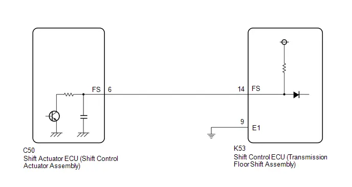
CAUTION / NOTICE / HINT
NOTICE:
- When removing or installing the shift control ECU or shift actuator
ECU, make sure there is no power supplied*1 when disconnecting or connecting
the connectors.
*1: Auxiliary battery, sub-battery, integrated capacitor, etc.
- When disconnecting a wire harness of any component connected to the supply power of the integrated capacitor or when removing the integrated capacitor, make sure to wait 5 minutes or more after turning the ignition switch off for self-diagnosis to complete and the voltage of the integrated capacitor to discharge.
- Before performing troubleshooting, check the fuses, connector connections and contact pressure of the relevant terminals for this circuit.
PROCEDURE
|
1. |
INSPECT SHIFT ACTUATOR ECU (SHIFT CONTROL ACTUATOR ASSSEMBLY) (CHECK FS TERMINAL WAVEFORM) |
Pre-procedure1
(a) Connect an oscilloscope between the shift control ECU (transmission floor shift assembly) terminals specified in the table below.
(b) Turn the ignition switch to ON.
Procedure1
|
(c) Measure the waveform.  Click Location & Routing(K53) Click
Connector(K53) Click Location & Routing(K53) Click
Connector(K53)
HINT: Perform the inspection with the connector of the shift control ECU and shift actuator ECU connected. Result:
|
|
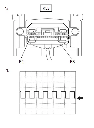
Post-procedure1
(d) Turn the ignition switch off.
| OK |
 |
REPLACE SHIFT CONTROL ECU (TRANSMISSION FLOOR SHIFT ASSEMBLY) |
|

|
2. |
CHECK HARNESS AND CONNECTOR (SHIFT CONTROL ECU - SHIFT ACTUATOR ECU) |
Pre-procedure1
(a) Disconnect the K53 shift control ECU (transmission floor shift assembly) connector.
(b) Disconnect the C50 shift actuator ECU (shift control actuator assembly) connector.
Procedure1
(c) Measure the resistance according to the value(s) in the table below.
Standard Resistance:
 Click Location & Routing(K53,C50) Click Connector(K53)
Click Connector(C50)
Click Location & Routing(K53,C50) Click Connector(K53)
Click Connector(C50)
|
Tester Connection |
Condition |
Specified Condition |
Result |
|---|---|---|---|
|
K53-14 (FS) - C50-6 (FS) |
Always |
Below 1 Ω |
Ω |
|
K53-14 (FS) or C50-6 (FS) - Body ground and other terminals |
Always |
10 kΩ or higher |
kΩ |
Post-procedure1
(d) Connect the shift actuator ECU (shift control actuator assembly) connector.
(e) Connect the shift control ECU (transmission floor shift assembly) connector.
| OK |
 |
REPLACE SHIFT ACTUATOR ECU (SHIFT CONTROL ACTUATOR ASSSEMBLY) |
| NG |
 |
REPAIR OR REPLACE HARNESS OR CONNECTOR |
Lost Communication with Gear Shift Control Module "B" (Local-CAN) Missing Message (P175387)
DESCRIPTION
The shift control ECU receives or sends a signal to or from the shift actuator ECU via CAN.
|
DTC No. |
Detection Item |
DTC Detection Condition |
Trouble Area |
MIL |
Warning Indicate |
DTC Output from |
Priority |
Note |
|---|---|---|---|---|---|---|---|---|
|
P175387 |
Lost Communication with Gear Shift Control Module "B" (Local-CAN) Missing Message |
When the ignition switch is ON and the auxiliary battery voltage is a certain value or more, a communication malfunction is continuously detected in the CAN (SBW BUS) by the shift actuator ECU (1 trip detection logic) |
|
Does not come on |
Multi-information Display Error Message
|
Hybrid Control |
A |
SAE: P1753 |
CONFIRMATION DRIVING PATTERN
HINT:
After repairs have been completed, clear the DTCs and then check that the Toyota Prius vehicle has returned to normal by performing the All Readiness check procedure.
Click here

- Turn the ignition switch to ON and wait for 1 minute or more.
WIRING DIAGRAM
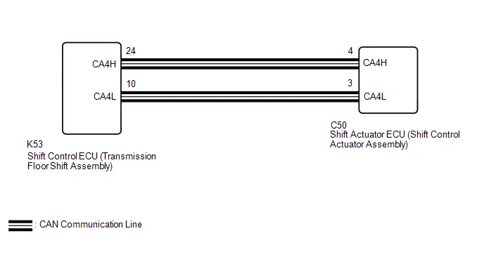
CAUTION / NOTICE / HINT
NOTICE:
- When removing or installing the shift control ECU or shift actuator
ECU, make sure there is no power supplied*1 when disconnecting or connecting
the connectors.
*1: Auxiliary battery, sub-battery, integrated capacitor, etc.
- When disconnecting a wire harness of any component connected to the supply power of the integrated capacitor or when removing the integrated capacitor, make sure to wait 5 minutes or more after turning the ignition switch off for self-diagnosis to complete and the voltage of the integrated capacitor to discharge.
- Before performing troubleshooting, check the fuses, connector connections and contact pressure of the relevant terminals for this circuit.
PROCEDURE
|
1. |
CHECK HARNESS AND CONNECTOR (SHIFT CONTROL ECU - SHIFT ACTUATOR ECU) |
Pre-procedure1
(a) Disconnect the K53 shift control ECU (transmission floor shift assembly) connector.
(b) Disconnect the C50 shift actuator ECU (shift control actuator assembly) connector.
Procedure1
(c) Measure the resistance according to the value(s) in the table below.
Standard Resistance:
 Click Location & Routing(K53,C50) Click Connector(K53)
Click Connector(C50)
Click Location & Routing(K53,C50) Click Connector(K53)
Click Connector(C50)
|
Tester Connection |
Condition |
Specified Condition |
Result |
|---|---|---|---|
|
K53-24 (CA4H) - C50-4 (CA4H) |
Always |
Below 1 Ω |
Ω |
|
K53-10 (CA4L) - C50-3 (CA4L) |
Always |
Below 1 Ω |
Ω |
|
K53-24 (CA4H) or C50-4 (CA4H) - Body ground and other terminals |
Always |
10 kΩ or higher |
kΩ |
|
K53-10 (CA4L) or C50-3 (CA4L) - Body ground and other terminals |
Always |
10 kΩ or higher |
kΩ |
Post-procedure1
(d) Connect the shift actuator ECU (shift control actuator assembly) connector.
(e) Connect the shift control ECU (transmission floor shift assembly) connector.
| NG |
 |
REPAIR OR REPLACE HARNESS OR CONNECTOR |
|

|
2. |
CHECK SHIFT ACTUATOR ECU (SHIFT CONTROL ACTUATOR ASSSEMBLY) |
Pre-procedure1
(a) Disconnect the K53 shift control ECU (transmission floor shift assembly) connector.
Procedure1
(b) Measure the resistance according to the value(s) in the table below.
Standard Resistance:
 Click Location & Routing(K53) Click Connector(K53)
|
Tester Connection |
Condition |
Specified Condition |
Result |
|---|---|---|---|
|
K53-24 (CA4H) - K53-10 (CA4L) |
Ignition switch off |
108 to 132 Ω |
Ω |
Post-procedure1
(c) Connect the shift control ECU (transmission floor shift assembly) connector.
| OK |
 |
REPLACE SHIFT CONTROL ECU (TRANSMISSION FLOOR SHIFT ASSEMBLY) |
| NG |
 |
REPLACE SHIFT ACTUATOR ECU (SHIFT CONTROL ACTUATOR ASSSEMBLY) |
Gear Shift Control Module "A" System Voltage Low (P1761A2)
DESCRIPTION
Auxiliary battery power is always supplied to the BATT terminal of the shift control ECU. Auxiliary battery supply power is continually supplied after the ignition switch is turned off.
|
DTC No. |
Detection Item |
DTC Detection Condition |
Trouble Area |
MIL |
Warning Indicate |
DTC Output from |
Priority |
Note |
|---|---|---|---|---|---|---|---|---|
|
P1761A2 |
Gear Shift Control Module "A" System Voltage Low |
BUB terminal voltage is a certain value or more and a low BATT terminal voltage is continuously detected (1 trip detection logic) |
|
Does not come on |
Multi-information Display Error Message
|
Hybrid Control |
A |
SAE: P1763 |
CONFIRMATION DRIVING PATTERN
HINT:
After repairs have been completed, clear the DTCs and then check that the Toyota Prius vehicle has returned to normal by performing the All Readiness check procedure.
Click here

- Turn the ignition switch to ON and wait for 1 minute or more.
WIRING DIAGRAM
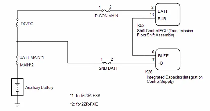
CAUTION / NOTICE / HINT
NOTICE:
- When removing or installing the shift control ECU or shift actuator
ECU, make sure there is no power supplied*1 when disconnecting or connecting
the connectors.
*1: Auxiliary battery, sub-battery, integrated capacitor, etc.
- When disconnecting a wire harness of any component connected to the supply power of the integrated capacitor or when removing the integrated capacitor, make sure to wait 5 minutes or more after turning the ignition switch off for self-diagnosis to complete and the voltage of the integrated capacitor to discharge.
- Before performing troubleshooting, check the fuses, connector connections and contact pressure of the relevant terminals for this circuit.
PROCEDURE
|
1. |
INSPECT AUXILIARY BATTERY TERMINAL (CONTACT PROBLEM) |
(a) Check the connection of the auxiliary battery terminal.
OK:
The battery is connected securely and there are no contact problems.
| NG |
 |
CONNECT SECURELY |
|

|
2. |
CHECK HARNESS AND CONNECTOR (BATT TERMINAL VOLTAGE) |
Pre-procedure1
(a) Disconnect the K53 shift control ECU (transmission floor shift assembly) connector.
Procedure1
(b) Measure the voltage according to the value(s) in the table below.
Standard Voltage:
 Click Location & Routing(K53) Click Connector(K53)
|
Tester Connection |
Condition |
Specified Condition |
Result |
|---|---|---|---|
|
K53-2 (BATT) - Body ground |
Ignition switch off |
11 to 14 V |
V |
Post-procedure1
(c) Connect the shift control ECU (transmission floor shift assembly) connector.
| OK |
 |
REPLACE SHIFT CONTROL ECU (TRANSMISSION FLOOR SHIFT ASSEMBLY) |
| NG |
 |
REPAIR OR REPLACE HARNESS OR CONNECTOR (BATT POWER SOURCE CIRCUIT) |
Sub Battery Module System Voltage Low (P1765A2)
DESCRIPTION
After the ignition switch is turned to ON, supply power ( B) is supplied to terminal BUB of the shift control ECU via the integrated capacitor.
If power is not supplied to terminal BUB even if power is supplied to the shift control ECU, the hybrid vehicle control ECU stores a DTC.
|
DTC No. |
Detection Item |
DTC Detection Condition |
Trouble Area |
MIL |
Warning Indicate |
DTC Output from |
Priority |
Note |
|---|---|---|---|---|---|---|---|---|
|
P1765A2 |
Sub Battery Module System Voltage Low |
The ignition switch is ON (IG) and the auxiliary battery voltage is a certain value or more, a low BUB terminal voltage is continuously detected (1 trip detection logic) |
|
Does not come on |
Multi-information Display Error Message
|
Hybrid Control |
A |
SAE: P1767 |
CONFIRMATION DRIVING PATTERN
HINT:
After repair has been completed, clear the DTC and then check that the Toyota Prius vehicle has returned to normal by performing the All Readiness check procedure.
Click here

- Turn the ignition switch to ON and wait for 1 minute or more.
WIRING DIAGRAM
Click here

CAUTION / NOTICE / HINT
NOTICE:
- When removing or installing the shift control ECU or shift actuator
ECU, make sure there is no power supplied*1 when disconnecting or connecting
the connectors.
*1: Auxiliary battery, sub-battery, integrated capacitor, etc.
- When disconnecting a wire harness of any component connected to the supply power of the integrated capacitor or when removing the integrated capacitor, make sure to wait 5 minutes or more after turning the ignition switch off for self-diagnosis to complete and the voltage of the integrated capacitor to discharge.
- Before performing troubleshooting, check the fuses, connector connections and contact pressure of the relevant terminals for this circuit.
PROCEDURE
|
1. |
INSPECT SHIFT CONTROL ECU (TRANSMISSION FLOOR SHIFT ASSEMBLY) (BUB TERMINAL VOLTAGE) |
Pre-procedure1
(a) Turn the ignition switch to ON.
Procedure1
|
(b) Measure the voltage according to the value(s) in the table below. Standard Voltage:  Click Location & Routing(K53) Click
Connector(K53) Click Location & Routing(K53) Click
Connector(K53)
Result:
|
|

Post-procedure1
(c) Turn the ignition switch off.
| OK |
 |
REPLACE SHIFT CONTROL ECU (TRANSMISSION FLOOR SHIFT ASSEMBLY) |
|

|
2. |
CHECK HARNESS AND CONNECTOR (SHIFT CONTROL ECU - INTEGRATED CAPACITOR) |
Pre-procedure1
(a) Disconnect the K53 shift control ECU (transmission floor shift assembly) connector.
(b) Disconnect the K26 integrated capacitor (integration control supply) connector.
Procedure1
(c) Measure the resistance according to the value(s) in the table below.
Standard Resistance:
 Click Location & Routing(K53,K26) Click Connector(K53)
Click Connector(K26)
Click Location & Routing(K53,K26) Click Connector(K53)
Click Connector(K26)
|
Tester Connection |
Condition |
Specified Condition |
Result |
|---|---|---|---|
|
K53-13 (BUB) - K26-6 (BUSE) |
Always |
Below 1 Ω |
Ω |
|
K53-13 (BUB) or K26-6 (BUSE) - Body ground and other terminals |
Always |
10 kΩ or higher |
kΩ |
Post-procedure1
(d) Connect the integrated capacitor (integration control supply) connector.
(e) Connect the shift control ECU (transmission floor shift assembly) connector.
| OK |
 |
REPLACE INTEGRATED CAPACITOR (INTEGRATION CONTROL SUPPLY)
|


| NG |
 |
REPAIR OR REPLACE HARNESS OR CONNECTOR |
Gear Shift Control Module "A" A/D Processing Performance (P176900)
DESCRIPTION
The shift control ECU monitors the AD convertor built into the shift control ECU, and if a malfunction is detected, the hybrid vehicle control ECU stores a DTC. The shift control ECU is built into the transmission floor shift assembly.
|
DTC No. |
Detection Item |
DTC Detection Condition |
Trouble Area |
MIL |
Warning Indicate |
DTC Output from |
Priority |
Note |
|---|---|---|---|---|---|---|---|---|
|
P176900 |
Gear Shift Control Module "A" A/D Processing Performance |
Internal malfunction of the shift control ECU (AD convertor malfunction) is detected (1 trip detection logic) |
Shift control ECU (transmission floor shift assembly) |
Does not come on |
Multi-information Display Error Message
|
Hybrid Control |
A |
SAE: P1769 |
CONFIRMATION DRIVING PATTERN
HINT:
After repairs have been completed, clear the DTCs and then check that the Toyota Prius vehicle has returned to normal by performing the All Readiness check procedure.
Click here

- Turn the ignition switch to ON and wait for 1 minute or more.
CAUTION / NOTICE / HINT
NOTICE:
- When removing or installing the shift control ECU or shift actuator
ECU, make sure there is no power supplied*1 when disconnecting or connecting
the connectors.
*1: Auxiliary battery, sub-battery, integrated capacitor, etc.
- When disconnecting a wire harness of any component connected to the supply power of the integrated capacitor or when removing the integrated capacitor, make sure to wait 5 minutes or more after turning the ignition switch off for self-diagnosis to complete and the voltage of the integrated capacitor to discharge.
- Before performing troubleshooting, check the fuses, connector connections and contact pressure of the relevant terminals for this circuit.
PROCEDURE
|
1. |
REPLACE SHIFT CONTROL ECU (TRANSMISSION FLOOR SHIFT ASSEMBLY) |
Click here

| NEXT |
 |
END |
IG2 Signal (Gear Shift Control Module "A") Circuit Short to Auxiliary Battery (P176D12)
DESCRIPTION
The shift control ECU compares the IGP signal to the IG control status signal sent from smart key ECU assembly (certification ECU assembly) to detect a stuck on malfunction of the IGP signal.
|
DTC No. |
Detection Item |
DTC Detection Condition |
Trouble Area |
MIL |
Warning Indicate |
DTC Output from |
Priority |
Note |
|---|---|---|---|---|---|---|---|---|
|
P176D12 |
IG2 Signal (Gear Shift Control Module "A") Circuit Short to Auxiliary Battery |
When all of the following conditions are met:
(1 trip detection logic) |
|
Does not come on |
Multi-information Display Error Message
|
Hybrid Control |
A |
SAE: P176F |
CONFIRMATION DRIVING PATTERN
HINT:
After repair has been completed, clear the DTC and then check that the Toyota Prius vehicle has returned to normal by performing the All Readiness check procedure.
Click here

- Turn the ignition switch to ON and wait for 1 minute or more.
- Turn the ignition switch to off and wait for 1 minute or more.
WIRING DIAGRAM
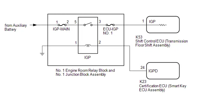
CAUTION / NOTICE / HINT
NOTICE:
- When removing or installing the shift control ECU or shift actuator
ECU, make sure there is no power supplied*1 when disconnecting or connecting
the connectors.
*1: Auxiliary battery, sub-battery, integrated capacitor, etc.
- When disconnecting a wire harness of any component connected to the supply power of the integrated capacitor or when removing the integrated capacitor, make sure to wait 5 minutes or more after turning the ignition switch off for self-diagnosis to complete and the voltage of the integrated capacitor to discharge.
- Before performing troubleshooting, check the fuses, connector connections and contact pressure of the relevant terminals for this circuit.
PROCEDURE
|
1. |
CHECK SHIFT CONTROL ECU (TRANSMISSION FLOOR SHIFT ASSEMBLY) (IGP TERMINAL VOLTAGE) |
Pre-procedure1
(a) Disconnect the K53 shift control ECU (transmission floor shift assembly) connector.
Procedure1
(b) Measure the voltage according to the value(s) in the table below.
Standard Voltage:
 Click Location & Routing(K53) Click Connector(K53)
|
Tester Connection |
Condition |
Specified Condition |
Result |
|---|---|---|---|
|
K53-1 (IGP) - Body ground |
Ignition switch off |
Below 1 V |
V |
Post-procedure1
(c) Connect the shift control ECU (transmission floor shift assembly) connector.
| NG |
 |
GO TO STEP 4 |
|

|
2. |
CLEAR DTC |
Pre-procedure1
(a) Turn the ignition switch to ON.
Procedure1
(b) Clear the DTCs.
Powertrain > Hybrid Control > Clear DTCsPost-procedure1
(c) Turn the ignition switch off.
(d) Disconnect the GTS.
(e) Leave the Toyota Prius vehicle as is for 60 seconds or more.
NOTICE:
- Do not connect the GTS.
- Do not depress the brake pedal.
- Do not open/close any of the doors.
|

|
3. |
CHECK DTC OUTPUT (PERFORM A REPRODUCTION TEST) |
Pre-procedure1
(a) Turn the ignition switch to ON and wait for 1 minute or more.
(b) Turn the ignition switch to OFF and wait for 1 minute or more.
(c) Turn the ignition switch to ON.
Procedure1
(d) Check for DTCs.
Powertrain > Hybrid Control > Trouble Codes|
Result |
Proceed to |
|---|---|
|
P176D12 is not output |
A |
|
P176D12 is output |
B |
Post-procedure1
(e) Turn the ignition switch off.
| A |
 |
END |
| B |
 |
REPLACE SHIFT CONTROL ECU (TRANSMISSION FLOOR SHIFT ASSEMBLY) |
|
4. |
CHECK HARNESS AND CONNECTOR (SHIFT CONTROL ECU - IGP RELAY) |
Pre-procedure1
(a) Disconnect the K53 shift control ECU (transmission floor shift assembly) connector.
(b) Remove the IGP relay from the No. 1 engine room relay block and No. 1 junction block assembly.
Procedure1
(c) Measure the voltage according to the value(s) in the table below.
Standard Voltage:
 Click Location & Routing(K53) Click Connector(K53)
|
Tester Connection |
Condition |
Specified Condition |
Result |
|---|---|---|---|
|
K53-1 (IGP) - Body ground |
Ignition switch off |
Below 1 V |
V |
Post-procedure1
(d) Install the IGP relay to the No. 1 engine room relay block and No. 1 junction block assembly.
(e) Connect the shift control ECU (transmission floor shift assembly) connector.
| NG |
 |
REPAIR OR REPLACE HARNESS OR CONNECTOR |
|

|
5. |
INSPECT RELAY (IGP) |
Pre-procedure1
(a) Remove the IGP relay from the No. 1 engine room relay block and No. 1 junction block assembly.
Procedure1
|
(b) Measure the resistance according to the value(s) in the table below. Standard Resistance:
Result:
|
|
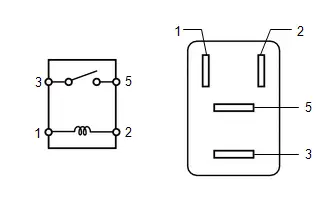
Post-procedure1
(c) Install the IGP relay to the No. 1 engine room relay block and No. 1 junction block assembly.
| NG |
 |
REPLACE RELAY (IGP) |
|

|
6. |
INSPECT CERTIFICATION ECU (SMART KEY ECU ASSEMBLY) |
Pre-procedure1
(a) None
Procedure1
(b) Measure the voltage according to the value(s) in the table below.
 Click Location & Routing(K23) Click Connector(K23)
|
Tester Connection |
Condition |
Specified Condition |
Result |
|---|---|---|---|
|
K23-24 (IGPD) - Body ground |
Ignition switch off |
Below 1 V |
V |
Post-procedure1
(c) None
| OK |
 |
CHECK FOR INTERMITTENT PROBLEMS Click here
Click here
|


|

|
7. |
CHECK HARNESS AND CONNECTOR (IGP RELAY - CERTIFICATION ECU (SMART KEY ECU ASSEMBLY)) |
Pre-procedure1
(a) Remove the IGP relay from the No. 1 engine room relay block and No. 1 junction block assembly.
(b) Disconnect the K23 certification ECU (smart key ECU Assembly) connector.
Procedure1
(c) Measure the voltage according to the value(s) in the table below.
Standard Voltage:
 Click Location & Routing(K23) Click Connector(K23)
|
Tester Connection |
Condition |
Specified Condition |
Result |
|---|---|---|---|
|
K23-24 (IGPD) - Body ground |
Ignition switch off |
Below 1 V |
V |
Post-procedure1
(d) Connect the certification ECU (smart key ECU Assembly) connector.
(e) Install the IGP relay to the No. 1 engine room relay block and No. 1 junction block assembly.
| OK |
 |
CHECK SMART KEY SYSTEM (FOR START FUNCTION) |
| NG |
 |
REPAIR OR REPLACE HARNESS OR CONNECTOR |
Gear Shift Control Module "B" System Voltage Low (P1771A2)
DESCRIPTION
The BAT1 terminal of the shift actuator ECU is always supplied auxiliary battery power. When power is being supplied from the integrated capacitor to terminal BUB1 of the shift actuator ECU and there is a failure of the voltage at terminal BAT1, the shift actuator ECU stores a DTC in the hybrid Toyota Prius vehicle control ECU.
|
DTC No. |
Detection Item |
DTC Detection Condition |
Trouble Area |
MIL |
Warning Indicate |
DTC Output from |
Priority |
Note |
|---|---|---|---|---|---|---|---|---|
|
P1771A2 |
Gear Shift Control Module "B" System Voltage Low |
When the ignition switch is ON (IG) and BUB1 terminal voltage is a certain value or more, a low BAT1 terminal voltage is detected (1 trip detection logic) |
|
Does not come on |
Multi-information Display Error Message
|
Hybrid Control |
A |
SAE: P1773 |
CONFIRMATION DRIVING PATTERN
HINT:
After repairs have been completed, clear the DTCs and then check that the Toyota Prius vehicle has returned to normal by performing the All Readiness check procedure.
Click here

- Turn the ignition switch to ON and wait for 1 minute or more.
WIRING DIAGRAM
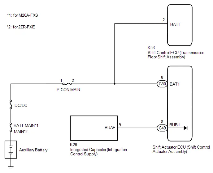
CAUTION / NOTICE / HINT
NOTICE:
- When removing or installing the shift control ECU or shift actuator
ECU, make sure there is no power supplied*1 when disconnecting or connecting
the connectors.
*1: Auxiliary battery, sub-battery, integrated capacitor, etc.
- When disconnecting a wire harness of any component connected to the supply power of the integrated capacitor or when removing the integrated capacitor, make sure to wait 5 minutes or more after turning the ignition switch off for self-diagnosis to complete and the voltage of the integrated capacitor to discharge.
- Before performing troubleshooting, check the fuses, connector connections and contact pressure of the relevant terminals for this circuit.
PROCEDURE
|
1. |
CHECK HARNESS AND CONNECTOR (BAT1 TERMINAL VOLTAGE) |
Pre-procedure1
(a) Disconnect the C50 shift actuator ECU (shift control actuator assembly) connector.
Procedure1
(b) Measure the voltage according to the value(s) in the table below.
Standard Voltage:
 Click Location & Routing(C50) Click Connector(C50)
|
Tester Connection |
Condition |
Specified Condition |
Result |
|---|---|---|---|
|
C50-8 (BAT1) - Body ground |
Ignition switch off |
11 to 14 V |
V |
Post-procedure1
(c) Connect the shift actuator ECU (shift control actuator assembly) connector.
| OK |
 |
REPLACE SHIFT ACTUATOR ECU (SHIFT CONTROL ACTUATOR ASSSEMBLY) |
| NG |
 |
REPAIR OR REPLACE HARNESS OR CONNECTOR (BAT1 POWER SOURCE CIRCUIT) |
Sub Battery Module (Gear Shift Control Module "B") System Voltage Low (P1775A2)
DESCRIPTION
Auxiliary battery power is supplied from the integrated capacitor to terminal BUB1 of the shift actuator ECU when the ignition switch is turned to ON (IG), and the supply power stops a few seconds after the ignition switch is turned off.
|
DTC No. |
Detection Item |
DTC Detection Condition |
Trouble Area |
MIL |
Warning Indicate |
DTC Output from |
Priority |
Note |
|---|---|---|---|---|---|---|---|---|
|
P1775A2 |
Sub Battery Module (Gear Shift Control Module "B") System Voltage Low |
Even though the voltage of the auxiliary battery is a certain voltage or more, the voltage at BUB1 is low (1 trip detection logic) |
|
Does not come on |
Multi-information Display Error Message
|
Hybrid Control |
A |
SAE: P1777 |
CONFIRMATION DRIVING PATTERN
HINT:
After repairs have been completed, clear the DTCs and then check that the Toyota Prius vehicle has returned to normal by performing the All Readiness check procedure.
Click here

- Turn the ignition switch to ON and wait for 1 minute or more.
WIRING DIAGRAM
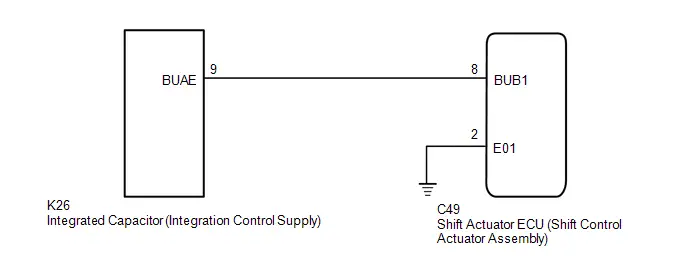
CAUTION / NOTICE / HINT
NOTICE:
- When removing or installing the shift control ECU or shift actuator
ECU, make sure there is no power supplied*1 when disconnecting or connecting
the connectors.
*1: Auxiliary battery, sub-battery, integrated capacitor, etc.
- When disconnecting a wire harness of any component connected to the supply power of the integrated capacitor or when removing the integrated capacitor, make sure to wait 5 minutes or more after turning the ignition switch off for self-diagnosis to complete and the voltage of the integrated capacitor to discharge.
- Before performing troubleshooting, check the fuses, connector connections and contact pressure of the relevant terminals for this circuit.
PROCEDURE
|
1. |
CHECK HARNESS AND CONNECTOR (BUB1 TERMINAL VOLTAGE) |
Pre-procedure1
(a) Disconnect the C49 shift actuator ECU (shift control actuator assembly) connector.
(b) Turn the ignition switch to ON.
Procedure1
(c) Measure the voltage according to the value(s) in the table below.
Standard Voltage:
 Click Location & Routing(C49) Click Connector(C49)
|
Tester Connection |
Condition |
Specified Condition |
Result |
|---|---|---|---|
|
C49-8 (BUB1) - Body ground |
Ignition switch ON |
11 to 14 V |
V |
NOTICE:
Turning the ignition switch to ON with the connector disconnected causes other DTCs to be stored. Clear the DTCs after performing this inspection.
Post-procedure1
(d) Turn the ignition switch off.
(e) Connect the shift actuator ECU (shift control actuator assembly) connector.
| OK |
 |
REPLACE SHIFT ACTUATOR ECU (SHIFT CONTROL ACTUATOR ASSSEMBLY) |
|

|
2. |
CHECK HARNESS AND CONNECTOR (SHIFT ACTUATOR ECU - INTEGRATED CAPACITOR) |
Pre-procedure1
(a) Disconnect the C49 shift actuator ECU (shift control actuator assembly) connector.
(b) Disconnect the K26 integrated capacitor (integration control supply) connector.
Procedure1
(c) Measure the resistance according to the value(s) in the table below.
Standard Resistance:
 Click Location & Routing(C49,K26) Click Connector(C49)
Click Connector(K26)
Click Location & Routing(C49,K26) Click Connector(C49)
Click Connector(K26)
|
Tester Connection |
Condition |
Specified Condition |
Result |
|---|---|---|---|
|
C49-8 (BUB1) - K26-9 (BUAE) |
Always |
Below 1 Ω |
Ω |
|
C49-8 (BUB1) or K26-9 (BUAE) - Body ground and other terminals |
Always |
10 kΩ or higher |
kΩ |
Post-procedure1
(d) Connect the integrated capacitor (integration control supply) connector.
(e) Connect the shift actuator ECU (shift control actuator assembly) connector.
| OK |
 |
REPLACE INTEGRATED CAPACITOR (INTEGRATION CONTROL SUPPLY)
|


| NG |
 |
REPAIR OR REPLACE HARNESS OR CONNECTOR |
Gear Shift Control Module Backup Power Supply Internal Electronic Failure (P177949)
DESCRIPTION
When an internal malfunction is detected by the integrated capacitor, the hybrid vehicle control ECU stores a DTC.
|
DTC No. |
Detection Item |
DTC Detection Condition |
Trouble Area |
MIL |
Warning Indicate |
DTC Output from |
Priority |
Note |
|---|---|---|---|---|---|---|---|---|
|
P177949 |
Gear Shift Control Module Backup Power Supply Internal Electronic Failure |
An internal malfunction is detected by the integrated capacitor (1 trip detection logic) |
Integrated capacitor (integration control supply) |
Does not come on |
Multi-information Display Error Message
|
Hybrid Control |
A |
SAE: P1779 |
CONFIRMATION DRIVING PATTERN
HINT:
After repair has been completed, clear the DTC and then check that the Toyota Prius vehicle has returned to normal by performing the All Readiness check procedure.
Click here

- Turn the ignition switch off and wait for 6 minutes or more.
- Turn the ignition switch to ON and wait for 10 seconds or more.
CAUTION / NOTICE / HINT
NOTICE:
- When removing or installing the shift control ECU or shift actuator
ECU, make sure there is no power supplied*1 when disconnecting or connecting
the connectors.
*1: Auxiliary battery, sub-battery, integrated capacitor, etc.
- When disconnecting a wire harness of any component connected to the supply power of the integrated capacitor or when removing the integrated capacitor, make sure to wait 5 minutes or more after turning the ignition switch off for self-diagnosis to complete and the voltage of the integrated capacitor to discharge.
- Before performing troubleshooting, check the fuses, connector connections and contact pressure of the relevant terminals for this circuit.
PROCEDURE
|
1. |
CHECK DTC OUTPUT (SUB BATTERY SYSTEM) |
Pre-procedure1
(a) Turn the ignition switch to ON.
Procedure1
(b) Check for DTCs.
Body Electrical > Sub Battery System > Trouble CodesPost-procedure1
(c) Turn the ignition switch off.
| NEXT |
 |
GO TO SUB BATTERY SYSTEM
|


Lost Communication with Gear Shift Control Module Backup Power Supply Missing Message (P177A87)
DESCRIPTION
The shift control ECU sends backup request signals to the integrated capacitor according to BUBO signals.
The shift control ECU receives backup mode and malfunction notification signals from the integrated capacitor according to BUBI signals.
|
DTC No. |
Detection Item |
DTC Detection Condition |
Trouble Area |
MIL |
Warning Indicate |
DTC Output from |
Priority |
Note |
|---|---|---|---|---|---|---|---|---|
|
P177A87 |
Lost Communication with Gear Shift Control Module Backup Power Supply Missing Message |
When the ignition switch is ON and the auxiliary battery voltage is a certain value or more, communication malfunction with the integrated capacitor is detected (1 trip detection logic) |
|
Does not come on |
Multi-information Display Error Message
|
Hybrid Control |
A |
SAE: P177A |
CONFIRMATION DRIVING PATTERN
HINT:
After repairs have been completed, clear the DTCs and then check that the Toyota Prius vehicle has returned to normal by performing the All Readiness check procedure.
Click here

- Turn the ignition switch to ON and wait for 1 minute or more.
WIRING DIAGRAM
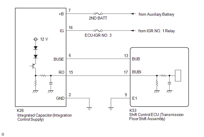
CAUTION / NOTICE / HINT
NOTICE:
- When removing or installing the shift control ECU or shift actuator
ECU, make sure there is no power supplied*1 when disconnecting or connecting
the connectors.
*1: Auxiliary battery, sub-battery, integrated capacitor, etc.
- When disconnecting a wire harness of any component connected to the supply power of the integrated capacitor or when removing the integrated capacitor, make sure to wait 5 minutes or more after turning the ignition switch off for self-diagnosis to complete and the voltage of the integrated capacitor to discharge.
- Before performing troubleshooting, check the fuses, connector connections and contact pressure of the relevant terminals for this circuit.
HINT:
If the power source circuit of the integrated capacitor is malfunctioning, DTC P177A87 will be stored as communication will not be established.
PROCEDURE
|
1. |
CHECK HARNESS AND CONNECTOR (SHIFT CONTROL ECU - INTEGRATED CAPACITOR) |
Pre-procedure1
(a) Disconnect the K53 shift control ECU (transmission floor shift assembly) connector.
(b) Disconnect the K26 integrated capacitor (integration control supply) connector.
Procedure1
(c) Measure the resistance according to the value(s) in the table below.
Standard Resistance:
 Click Location & Routing(K53,K26) Click Connector(K53)
Click Connector(K26)
Click Location & Routing(K53,K26) Click Connector(K53)
Click Connector(K26)
|
Tester Connection |
Condition |
Specified Condition |
Result |
|---|---|---|---|
|
K53-17 (BUBI) - K26-15 (RO) |
Always |
Below 1 Ω |
Ω |
|
K53-17 (BUBI) or K26-15 (RO) - Body ground and other terminals |
Always |
10 kΩ or higher |
kΩ |
Post-procedure1
(d) Connect the integrated capacitor (integration control supply) connector.
(e) Connect the shift control ECU (transmission floor shift assembly) connector.
| NG |
 |
REPAIR OR REPLACE HARNESS OR CONNECTOR |
|

|
2. |
INSPECT SHIFT CONTROL ECU (TRANSMISSION FLOOR SHIFT ASSEMBLY) (CHECK BUBI TERMINAL WAVEFORM) |
Pre-procedure1
(a) Connect an oscilloscope between the shift control ECU (transmission floor shift assembly) terminals specified in the table below.
(b) Turn the ignition switch to ON.
Procedure1
|
(c) Measure the waveform.  Click Location & Routing(K53) Click
Connector(K53) Click Location & Routing(K53) Click
Connector(K53)
HINT: The duty ratio changes according to the Toyota Prius vehicle condition. Result:
|
|
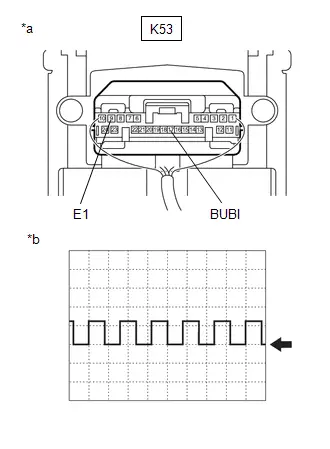
Post-procedure1
(d) Turn the ignition switch off.
| OK |
 |
REPLACE SHIFT CONTROL ECU (TRANSMISSION FLOOR SHIFT ASSEMBLY) |
|

|
3. |
INSPECT INTEGRATED CAPACITOR (INTEGRATION CONTROL SUPPLY) ( B TERMINAL VOLTAGE) |
Pre-procedure1
(a) Disconnect the K26 integrated capacitor (integration control supply) connector.
Procedure1
(b) Measure the voltage according to the value(s) in the table below.
Standard Voltage:
 Click Location & Routing(K26) Click Connector(K26)
|
Tester Connection |
Condition |
Specified Condition |
Result |
|---|---|---|---|
|
K26-7 ( B) - Body ground |
Always |
11 to 14 V |
V |
Post-procedure1
(c) Connect the integrated capacitor (integration control supply) connector.
| NG |
 |
REPAIR OR REPLACE HARNESS OR CONNECTOR |
|

|
4. |
INSPECT INTEGRATED CAPACITOR (INTEGRATION CONTROL SUPPLY) (IG TERMINAL VOLTAGE) |
Pre-procedure1
(a) Disconnect the K26 integrated capacitor (integration control supply) connector.
(b) Turn the ignition switch to ON.
Procedure1
(c) Measure the voltage according to the value(s) in the table below.
Standard Voltage:
 Click Location & Routing(K26) Click Connector(K26)
|
Tester Connection |
Condition |
Specified Condition |
Result |
|---|---|---|---|
|
K26-16 (IG) - Body ground |
Ignition switch to ON |
11 to 14 V |
V |
NOTICE:
Turning the ignition switch to ON with the connector disconnected causes other DTCs to be stored. Clear the DTCs after performing this inspection.
Post-procedure1
(d) Turn the ignition switch off.
(e) Connect the integrated capacitor (integration control supply) connector.
| NG |
 |
REPAIR OR REPLACE HARNESS OR CONNECTOR |
|

|
5. |
CHECK HARNESS AND CONNECTOR (SHIFT CONTROL ECU - INTEGRATED CAPACITOR) |
Pre-procedure1
(a) Disconnect the K53 shift control ECU (transmission floor shift assembly) connector.
(b) Disconnect the K26 integrated capacitor (integration control supply) connector.
Procedure1
(c) Measure the resistance according to the value(s) in the table below.
Standard Resistance:
 Click Location & Routing(K53,K26) Click Connector(K53)
Click Connector(K26)
Click Location & Routing(K53,K26) Click Connector(K53)
Click Connector(K26)
|
Tester Connection |
Condition |
Specified Condition |
Result |
|---|---|---|---|
|
K53-13 (BUB) - K26-6 (BUSE) |
Always |
Below 1 Ω |
Ω |
|
K53-13 (BUB) or K26-6 (BUSE) - Body ground and other terminals |
Always |
10 kΩ or higher |
kΩ |
Post-procedure1
(d) Connect the integrated capacitor (integration control supply) connector.
(e) Connect the shift control ECU (transmission floor shift assembly) connector.
| OK |
 |
REPLACE INTEGRATED CAPACITOR (INTEGRATION CONTROL SUPPLY)
|


| NG |
 |
REPAIR OR REPLACE HARNESS OR CONNECTOR |
Lost Communication with Gear Shift Control Module "A" from "B" Missing Message (P178987)
DESCRIPTION
The shift actuator ECU receives or sends a signal from or to the shift control ECU via CAN.
|
DTC No. |
Detection Item |
DTC Detection Condition |
Trouble Area |
MIL |
Warning Indicate |
DTC Output from |
Priority |
Note |
|---|---|---|---|---|---|---|---|---|
|
P178987 |
Lost Communication with Gear Shift Control Module "A" from "B" Missing Message |
When the ignition switch is ON (IG) and the auxiliary battery voltage is a certain value or more, a CAN communication malfunction with the shift control ECU is detected (1 trip detection logic) |
|
Does not come on |
Multi-information Display Error Message
|
Hybrid Control |
A |
SAE: P1789 |
CONFIRMATION DRIVING PATTERN
HINT:
After repairs have been completed, clear the DTCs and then check that the Toyota Prius vehicle has returned to normal by performing the All Readiness check procedure.
Click here

- Turn the ignition switch to ON and wait for 1 minute or more.
WIRING DIAGRAM
Click here

CAUTION / NOTICE / HINT
NOTICE:
- When removing or installing the shift control ECU and shift actuator
ECU, make sure there is no power supplied*1 when disconnecting or connecting
the connectors.
*1: Battery, sub-battery, integrated capacitor, etc.
- When disconnecting a wire harness of any component connected to the supply power of the integrated capacitor or when removing the integrated capacitor, make sure to wait 5 minutes or more after turning the ignition switch off for self-diagnosis to complete and the voltage of the integrated capacitor to discharge.
- Before performing troubleshooting, check the fuses, connector connections and contact pressure of the relevant terminals for this circuit.
PROCEDURE
|
1. |
CHECK HARNESS AND CONNECTOR (SHIFT CONTROL ECU - SHIFT ACTUATOR ECU) |
Pre-procedure1
(a) Disconnect the K53 shift control ECU (transmission floor shift assembly) connector.
(b) Disconnect the C50 shift actuator ECU (shift control actuator assembly) connector.
Procedure1
(c) Measure the resistance according to the value(s) in the table below.
Standard Resistance:
 Click Location & Routing(K53,C50) Click Connector(K53)
Click Connector(C50)
Click Location & Routing(K53,C50) Click Connector(K53)
Click Connector(C50)
|
Tester Connection |
Condition |
Specified Condition |
Result |
|---|---|---|---|
|
K53-24 (CA4H) - C50-4 (CA4H) |
Ignition switch off |
Below 1 Ω |
Ω |
|
K53-10 (CA4L) - C50-3 (CA4L) |
Ignition switch off |
Below 1 Ω |
Ω |
|
K53-24 (CA4H) or C50-4 (CA4H) - Body ground and other terminals |
Ignition switch off |
10 kΩ or higher |
kΩ |
|
K53-10 (CA4L) or C50-3 (CA4L) - Body ground and other terminals |
Ignition switch off |
10 kΩ or higher |
kΩ |
Post-procedure1
(d) Connect the shift actuator ECU (shift control actuator assembly) connector.
(e) Connect the shift control ECU (transmission floor shift assembly) connector.
| NG |
 |
REPAIR OR REPLACE HARNESS OR CONNECTOR |
|

|
2. |
CHECK SHIFT CONTROL ECU (TRANSMISSION FLOOR SHIFT ASSEMBLY) |
Pre-procedure1
(a) Disconnect the C50 shift actuator ECU (shift control actuator assembly) connector.
Procedure1
(b) Measure the resistance according to the value(s) in the table below.
Standard Resistance:
 Click Location & Routing(C50) Click Connector(C50)
|
Tester Connection |
Condition |
Specified Condition |
Result |
|---|---|---|---|
|
C50-4 (CA4H) - C50-3 (CA4L) |
Ignition switch off |
108 to 132 Ω |
Ω |
Post-procedure1
(c) Connect the shift actuator ECU (shift control actuator assembly) connector.
| OK |
 |
REPLACE SHIFT ACTUATOR ECU (SHIFT CONTROL ACTUATOR ASSSEMBLY) |
| NG |
 |
REPLACE SHIFT CONTROL ECU (TRANSMISSION FLOOR SHIFT ASSEMBLY) |
Gear Shift Control Module "B" Wake-up Circuit Short to Ground or Open (P178A14)
DESCRIPTION
The shift actuator ECU starts when it receives a WAKE signal from the shift control ECU.
|
DTC No. |
Detection Item |
DTC Detection Condition |
Trouble Area |
MIL |
Warning Indicate |
DTC Output from |
Priority |
Note |
|---|---|---|---|---|---|---|---|---|
|
P178A14 |
Gear Shift Control Module "B" Wake-up Circuit Short to Ground or Open |
When the auxiliary battery voltage and BAT1 terminal voltage are a certain value or more, a low WAKE terminal voltage is continuously detected (1 trip detection logic) |
|
Does not come on |
Multi-information Display Error Message
|
Hybrid Control |
A |
SAE: P178B |
CONFIRMATION DRIVING PATTERN
HINT:
After repairs have been completed, clear the DTCs and then check that the Toyota Prius vehicle has returned to normal by performing the All Readiness check procedure.
Click here

- Turn the ignition switch to ON and wait for 1 minute or more.
WIRING DIAGRAM
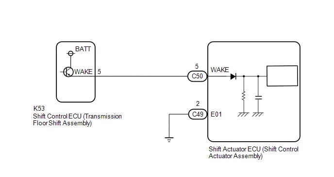
CAUTION / NOTICE / HINT
NOTICE:
- When removing or installing the shift control ECU or shift actuator
ECU, make sure there is no power supplied*1 when disconnecting or connecting
the connectors.
*1: Auxiliary battery, sub-battery, integrated capacitor, etc.
- When disconnecting a wire harness of any component connected to the supply power of the integrated capacitor or when removing the integrated capacitor, make sure to wait 5 minutes or more after turning the ignition switch off for self-diagnosis to complete and the voltage of the integrated capacitor to discharge.
- Before performing troubleshooting, check the fuses, connector connections and contact pressure of the relevant terminals for this circuit.
PROCEDURE
|
1. |
CHECK HARNESS AND CONNECTOR (WAKE TERMINAL VOLTAGE) |
Pre-procedure1
(a) Disconnect the C50 shift actuator ECU (shift control actuator assembly) connector.
(b) Turn the ignition switch to ON.
NOTICE:
Turning the ignition switch to ON with the connector disconnected causes other DTCs to be stored. Clear the DTCs after performing this inspection.
Procedure1
(c) Measure the voltage according to the value(s) in the table below.
Standard Voltage:
 Click Location & Routing(C50) Click Connector(C50)
|
Tester Connection |
Condition |
Specified Condition |
Result |
|---|---|---|---|
|
C50-5 (WAKE) - Body ground |
Ignition switch ON |
11 to 14 V |
V |
Post-procedure1
(d) Turn the ignition switch off.
(e) Connect the shift actuator ECU (shift control actuator assembly) connector.
| OK |
 |
REPLACE SHIFT ACTUATOR ECU (SHIFT CONTROL ACTUATOR ASSSEMBLY) |
|

|
2. |
CHECK HARNESS AND CONNECTOR (SHIFT ACTUATOR ECU - SHIFT CONTROL ECU) |
Pre-procedure1
(a) Disconnect the C50 shift actuator ECU (shift control actuator assembly) connector.
(b) Disconnect the K53 shift control ECU (transmission floor shift assembly) connector.
Procedure1
(c) Measure the resistance according to the value(s) in the table below.
Standard Resistance:
 Click Location & Routing(C50,K53) Click Connector(C50)
Click Connector(K53)
Click Location & Routing(C50,K53) Click Connector(C50)
Click Connector(K53)
|
Tester Connection |
Condition |
Specified Condition |
Result |
|---|---|---|---|
|
C50-5 (WAKE) - K53-5 (WAKE) |
Always |
Below 1 Ω |
Ω |
|
C50-5 (WAKE) or K53-5 (WAKE) - Body ground and other terminals |
Always |
10 kΩ or higher |
kΩ |
Post-procedure1
(d) Connect the shift control ECU (transmission floor shift assembly) connector.
(e) Connect the shift actuator ECU (shift control actuator assembly) connector.
| OK |
 |
REPLACE SHIFT CONTROL ECU (TRANSMISSION FLOOR SHIFT ASSEMBLY) |
| NG |
 |
REPAIR OR REPLACE HARNESS OR CONNECTOR |
Gear Shift Actuator "A" Supply Voltage "A" Circuit Short to Ground or Open (P179014)
DESCRIPTION
Auxiliary battery power is supplied to the MA1 terminal of the shift actuator ECU.
|
DTC No. |
Detection Item |
DTC Detection Condition |
Trouble Area |
MIL |
Warning Indicate |
DTC Output from |
Priority |
Note |
|---|---|---|---|---|---|---|---|---|
|
P179014 |
Gear Shift Actuator "A" Supply Voltage "A" Circuit Short to Ground or Open |
When the auxiliary battery voltage is a certain value or more, a low MA1 terminal voltage is continuously detected |
|
Does not come on |
Multi-information Display Error Message
|
Hybrid Control |
A |
SAE: P1791 |
CONFIRMATION DRIVING PATTERN
HINT:
After repairs have been completed, clear the DTCs and then check that the Toyota Prius vehicle has returned to normal by performing the All Readiness check procedure.
Click here

- Turn the ignition switch to ON and wait for 1 minute or more.
WIRING DIAGRAM

CAUTION / NOTICE / HINT
NOTICE:
- When removing or installing the shift control ECU or shift actuator
ECU, make sure there is no power supplied*1 when disconnecting or connecting
the connectors.
*1: Auxiliary battery, sub-battery, integrated capacitor, etc.
- When disconnecting a wire harness of any component connected to the supply power of the integrated capacitor or when removing the integrated capacitor, make sure to wait 5 minutes or more after turning the ignition switch off for self-diagnosis to complete and the voltage of the integrated capacitor to discharge.
- Before performing troubleshooting, check the fuses, connector connections and contact pressure of the relevant terminals for this circuit.
PROCEDURE
|
1. |
READ VALUE USING GTS (GEAR SHIFT ACTUATOR POWER SUPPLY VOLTAGE (MA1)) |
Pre-procedure1
(a) Turn the ignition switch to ON.
Procedure1
(b) Read the Data List according to the display on the GTS.
Powertrain > Hybrid Control > Data List|
Tester Display |
|---|
|
Gear Shift Actuator Power Supply Voltage (MA1) |
|
Result |
Proceed to |
|---|---|
|
The value of Gear Shift Actuator Power Supply Voltage (MA1) is 1.5 V or more |
A |
|
The value of Gear Shift Actuator Power Supply Voltage (MA1) is less than 1.5 V |
B |
Post-procedure1
(c) Turn the ignition switch off.
| B |
 |
GO TO STEP 4 |
|

|
2. |
CLEAR DTC |
Pre-procedure1
(a) Turn the ignition switch to ON.
Procedure1
(b) Clear the DTCs.
Powertrain > Hybrid Control > Clear DTCsPost-procedure1
(c) Turn the ignition switch off.
(d) Disconnect the GTS.
(e) Leave the Toyota Prius vehicle as is for 60 seconds or more.
NOTICE:
- Do not connect the GTS.
- Do not depress the brake pedal.
- Do not open/close any of the doors.
|

|
3. |
CHECK DTC OUTPUT (PERFORM A REPRODUCTION TEST) |
Pre-procedure1
(a) Turn the ignition switch to ON and wait for 1 minute or more.
Procedure1
(b) Check for DTCs.
Powertrain > Hybrid Control > Trouble Codes|
Result |
Proceed to |
|---|---|
|
P179014 is not output |
A |
|
P179014 is output |
B |
Post-procedure1
(c) Turn the ignition switch off.
| A |
 |
END |
| B |
 |
REPLACE SHIFT ACTUATOR ECU (SHIFT CONTROL ACTUATOR ASSSEMBLY) |
|
4. |
CHECK HARNESS AND CONNECTOR (MA1 TERMINAL VOLTAGE) |
Pre-procedure1
(a) Disconnect the C49 shift actuator ECU (shift control actuator assembly) connector.
Procedure1
(b) Measure the voltage according to the value(s) in the table below.
Standard Voltage:
 Click Location & Routing(C49) Click Connector(C49)
|
Tester Connection |
Condition |
Specified Condition |
|---|---|---|
|
C49-1 (MA1) - Body ground |
Ignition switch off |
11 to 14 V |
Post-procedure1
(c) Connect the shift actuator ECU (shift control actuator assembly) connector.
| OK |
 |
REPLACE SHIFT ACTUATOR ECU (SHIFT CONTROL ACTUATOR ASSSEMBLY) |
| NG |
 |
REPAIR OR REPLACE HARNESS OR CONNECTOR (MA1 POWER SUPPLY CIRCUIT) |
Gear Shift Actuator "A" Supply Voltage "B" Circuit Short to Ground or Open (P179314)
DESCRIPTION
Auxiliary battery power is supplied from the integrated capacitor to terminal MA2 of the shift actuator ECU when the ignition switch is turned to ON (IG), and the supply power stops a few seconds after the ignition switch is turned off.
|
DTC No. |
Detection Item |
DTC Detection Condition |
Trouble Area |
MIL |
Warning Indicate |
DTC Output from |
Priority |
Note |
|---|---|---|---|---|---|---|---|---|
|
P179314 |
Gear Shift Actuator "A" Supply Voltage "B" Circuit Short to Ground or Open |
Either of the following is met:
(1 trip detection logic) |
|
Does not come on |
Multi-information Display Error Message
|
Hybrid Control |
A |
SAE: P1794 |
CONFIRMATION DRIVING PATTERN
HINT:
After repairs have been completed, clear the DTCs and then check that the Toyota Prius vehicle has returned to normal by performing the All Readiness check procedure.
Click here

- Turn the ignition switch to ON and wait for 30 seconds or more.
- Turn the ignition switch off and wait for 30 seconds or more.
- Repeat the above steps 2 times.
WIRING DIAGRAM

CAUTION / NOTICE / HINT
NOTICE:
- When removing or installing the shift control ECU or shift actuator
ECU, make sure there is no power supplied*1 when disconnecting or connecting
the connectors.
*1: Auxiliary battery, sub-battery, integrated capacitor, etc.
- When disconnecting a wire harness of any component connected to the supply power of the integrated capacitor or when removing the integrated capacitor, make sure to wait 5 minutes or more after turning the ignition switch off for self-diagnosis to complete and the voltage of the integrated capacitor to discharge.
- Before performing troubleshooting, check the fuses, connector connections and contact pressure of the relevant terminals for this circuit.
- After replacing components or performing repairs, turn the ignition switch from ON to off to ON 2 times. Make sure to perform with an interval of 30 seconds or more.
PROCEDURE
|
1. |
CHECK HARNESS AND CONNECTOR (MA2 TERMINAL VOLTAGE) |
Pre-procedure1
(a) Disconnect the C49 shift actuator ECU (shift control actuator assembly) connector.
(b) Turn the ignition switch to ON.
Procedure1
(c) Measure the voltage according to the value(s) in the table below.
Standard Voltage:
 Click Location & Routing(C49) Click Connector(C49)
|
Tester Connection |
Condition |
Specified Condition |
Result |
|---|---|---|---|
|
C49-6 (MA2) - Body ground |
Ignition switch ON |
11 to 14 V |
V |
NOTICE:
Turning the ignition switch to ON with the connector disconnected causes other DTCs to be stored. Clear the DTCs after performing this inspection.
Post-procedure1
(d) Turn the ignition switch off.
(e) Connect the shift actuator ECU (shift control actuator assembly) connector.
| OK |
 |
REPLACE SHIFT ACTUATOR ECU (SHIFT CONTROL ACTUATOR ASSSEMBLY) |
|

|
2. |
CHECK HARNESS AND CONNECTOR (SHIFT ACTUATOR ECU - INTEGRATED CAPACITOR) |
Pre-procedure1
(a) Disconnect the C49 shift actuator ECU (shift control actuator assembly) connector.
(b) Disconnect the K26 integrated capacitor (integration control supply) connector.
Procedure1
(c) Measure the resistance according to the value(s) in the table below.
Standard Resistance:
 Click Location & Routing(C49,K26) Click
Connector(C49) Click Connector(K26)
Click Location & Routing(C49,K26) Click
Connector(C49) Click Connector(K26)
|
Tester Connection |
Condition |
Specified Condition |
Result |
|---|---|---|---|
|
C49-6 (MA2) - K26-19 (BUA) |
Always |
Below 1 Ω |
Ω |
|
C49-6 (MA2) or K26-19 (BUA) - Body ground and other terminals |
Always |
10 kΩ or higher |
kΩ |
Procedure2
(d) Measure the voltage according to the value(s) in the table below.
Standard Voltage:
 Click Location & Routing(C49) Click Connector(C49)
|
Tester Connection |
Condition |
Specified Condition |
Result |
|---|---|---|---|
|
C49-6 (MA2) - Body ground |
Ignition switch off |
Below 1 V |
V |
Post-procedure1
(e) Connect the integrated capacitor (integration control supply) connector.
(f) Connect the shift actuator ECU (shift control actuator assembly) connector.
| OK |
 |
REPLACE INTEGRATED CAPACITOR (INTEGRATION CONTROL SUPPLY)
|


| NG |
 |
REPAIR OR REPLACE HARNESS OR CONNECTOR |
Gear Shift Actuator "A" Control Circuit Internal Electronic Failure (P179C49)
DESCRIPTION
The shift actuator ECU monitors the ECU internal operation, and if a malfunction is detected, the hybrid vehicle control ECU stores a DTC.
|
DTC No. |
Detection Item |
DTC Detection Condition |
Trouble Area |
MIL |
Warning Indicate |
DTC Output from |
Priority |
Note |
|---|---|---|---|---|---|---|---|---|
|
P179C49 |
Gear Shift Actuator "A" Control Circuit Internal Electronic Failure |
An internal malfunction is detected (1 trip detection logic) |
Shift actuator ECU (shift control actuator assembly) |
Does not come on |
Multi-information Display Error Message
|
Hybrid Control |
A |
SAE: P179C |
CONFIRMATION DRIVING PATTERN
HINT:
After repairs have been completed, clear the DTCs and then check that the Toyota Prius vehicle has returned to normal by performing the All Readiness check procedure.
Click here

- Turn the ignition switch to ON and wait for 1 minutes or more.
CAUTION / NOTICE / HINT
NOTICE:
- When removing or installing the shift control ECU or shift actuator
ECU, make sure there is no power supplied*1 when disconnecting or connecting
the connectors.
*1: Auxiliary battery, sub-battery, integrated capacitor, etc.
- When disconnecting a wire harness of any component connected to the supply power of the integrated capacitor or when removing the integrated capacitor, make sure to wait 5 minutes or more after turning the ignition switch off for self-diagnosis to complete and the voltage of the integrated capacitor to discharge.
- Before performing troubleshooting, check the fuses, connector connections and contact pressure of the relevant terminals for this circuit.
PROCEDURE
|
1. |
REPLACE SHIFT ACTUATOR ECU (SHIFT CONTROL ACTUATOR ASSSEMBLY) |
Click here

| NEXT |
 |
END |
Gear Shift Actuator "A" Performance (P179E00)
DESCRIPTION
The shift control actuator assembly consists of a shift actuator ECU, motor, motor rotation angle sensor and output shaft rotation angle sensor. The shift control actuator assembly operates the motor in accordance with the operation signal from the shift control ECU to change the shift state between P and other than P.
The motor rotation sensor detects the motor rotation angle and optimizes the motor speed and current. The output shaft rotation angle sensor determines the shift state based on the sensor angle and transmits the state to the shift control ECU.
If the shift actuator ECU determines that the motor is malfunctioning or the detected motor rotation angle or output angle is not correct, the hybrid Toyota Prius vehicle control ECU stores a DTC.
|
DTC No. |
Detection Item |
DTC Detection Condition |
Trouble Area |
MIL |
Warning Indicate |
DTC Output from |
Priority |
Note |
|---|---|---|---|---|---|---|---|---|
|
P179E00 |
Gear Shift Actuator "A" Performance |
Either of the following is met:
(1 trip detection logic) |
|
Does not come on |
Multi-information Display Error Message
|
Hybrid Control |
B |
SAE: P179E |
CONFIRMATION DRIVING PATTERN
HINT:
After repairs have been completed, clear the DTCs and then check that the Toyota Prius vehicle has returned to normal by performing the All Readiness check procedure.
Click here

- With the brake pedal depressed, perform a shift operation then change the shift state to N.
- Press the P position switch to change the shift state to P.
WIRING DIAGRAM
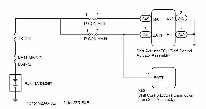
CAUTION / NOTICE / HINT
NOTICE:
- If initialization and learning of the shift actuator ECU (shift control
actuator assembly) has not been performed, this DTC may be stored. If the
shift actuator ECU (shift control actuator assembly) is replaced or removed,
make sure to perform actuator position learning.
Click here

- When removing or installing the shift control ECU or shift actuator
ECU, make sure there is no power supplied*1 when disconnecting or connecting
the connectors.
*1: Auxiliary battery, sub-battery, integrated capacitor, etc.
- This DTC may be stored if the auxiliary battery voltage is abnormal. Confirm the connection condition of the auxiliary battery before inspection.
- When disconnecting a wire harness of any component connected to the supply power of the integrated capacitor or when removing the integrated capacitor, make sure to wait 5 minutes or more after turning the ignition switch off for self-diagnosis to complete and the voltage of the integrated capacitor to discharge.
- Before performing troubleshooting, check the fuses, connector connections and contact pressure of the relevant terminals for this circuit.
PROCEDURE
|
1. |
CHECK Toyota Prius Vehicle CONDITION |
(a) Check for removal and installation history of the shift actuator ECU (shift control actuator assembly).
HINT:
If the shift actuator ECU (shift control actuator assembly) has been replaced or removed, make sure to perform actuator position learning. Check for removal and installation history as this DTC may be stored if the learning has not been completed.
|
Result |
Proceed to |
|---|---|
|
History exists |
A |
|
No history |
B |
| B |
 |
GO TO STEP 5 |
|

|
2. |
CLEAR DTC |
Pre-procedure1
(a) Turn the ignition switch to ON.
Procedure1
(b) Clear the DTCs.
Powertrain > Hybrid Control > Clear DTCsPost-procedure1
(c) Turn the ignition switch off.
(d) Disconnect the GTS.
(e) Leave the Toyota Prius vehicle as is for 60 seconds or more.
NOTICE:
- Do not connect the GTS.
- Do not depress the brake pedal.
- Do not open/close any of the doors.
|

|
3. |
PERFORM UTILITY (ACT POSITION LEARNING) |
Pre-procedure1
(a) Turn the ignition switch to ON.
Procedure1
(b) Perform ACT Position Learning.
HINT:
Click here

|
Tester Display |
|---|
|
ACT Position Learning |
Post-procedure1
(c) Turn the ignition switch off.
|

|
4. |
CHECK DTC OUTPUT (PERFORM A REPRODUCTION TEST) |
Pre-procedure1
(a) Turn the ignition switch to ON.
(b) With the brake pedal depressed, perform a shift operation then change the shift state to N.
(c) Press the P position switch to change the shift state to P.
Procedure1
(d) Check for DTCs.
Powertrain > Hybrid Control > Trouble Codes|
Result |
Proceed to |
|---|---|
|
P179E00 is not output |
A |
|
P179E00 is output |
B |
Post-procedure1
(e) Turn the ignition switch off.
| A |
 |
END |
|

|
5. |
CHECK DTC OUTPUT (HYBRID CONTROL) |
Pre-procedure1
(a) Turn the ignition switch to ON.
Procedure1
(b) Check if DTCs are output.
Powertrain > Hybrid Control > Trouble Codes|
Result |
Proceed to |
|---|---|
|
No DTCs in the table below are output |
A |
|
P179E00 and any DTCs in the table below are output |
B |
|
Priority |
Relevant DTC |
|
|---|---|---|
|
1 |
P175387 |
Lost Communication with Gear Shift Control Module "B" (Local-CAN) Missing Message |
|
P178987 |
Lost Communication with Gear Shift Control Module "A" from "B" Missing Message |
|
|
P179014 |
Gear Shift Actuator "A" Supply Voltage "A" Circuit Short to Ground or Open |
|
|
P18B200 |
Gear Shift Control Module "B" Motor Angle Sensor "A" Performance |
|
|
P18B562 |
Gear Shift Actuator "A" Phase U-V-W Current Sensor Signal Compare Failure |
|
|
U117000 |
Lost Communication with Brake System Control Module (Gear Shift Control Module "A") |
|
|
2 |
P179C49 |
Gear Shift Actuator "A" Control Circuit Internal Electronic Failure |
HINT:
The chart above is listed in inspection order of priority.
Post-procedure1
(c) Turn the ignition switch off.
| B |
 |
GO TO DTC CHART (ELECTRONIC SHIFT LEVER SYSTEM) |
|

|
6. |
INSPECT AUXILIARY BATTERY TERMINAL (CONTACT PROBLEM) |
(a) Check the connection of the auxiliary battery terminal.
OK:
The auxiliary battery is connected securely and there are no contact problems.
HINT:
Perform an inspection with consideration of a power supply voltage interruption due to a loose terminal, poor connection, etc.
| NG |
 |
CONNECT SECURELY |
|

|
7. |
CHECK HARNESS AND CONNECTOR (AUXILIARY BATTERY - SHIFT ACTUATOR ECU) |
Pre-procedure1
(a) Disconnect the C49 and C50 shift actuator ECU (shift control actuator assembly) connectors.
Procedure1
(b) Measure the voltage according to the value(s) in the table below.
Standard Voltage:
 Click Location & Routing(C50,C49) Click
Connector(C50) Click Connector(C49)
Click Location & Routing(C50,C49) Click
Connector(C50) Click Connector(C49)
|
Tester Connection |
Condition |
Specified Condition |
|---|---|---|
|
C50-8 (BAT1) - Body ground |
Always |
11 to 14 V |
|
C49-1 (MA1) - Body ground |
Always |
11 to 14 V |
Post-procedure1
(c) Connect the shift actuator ECU (shift control actuator assembly) connectors.
| NG |
 |
REPAIR OR REPLACE HARNESS OR CONNECTOR (AUXILIARY BATTERY - SHIFT ACTUATOR ECU) |
|

|
8. |
CHECK HARNESS AND CONNECTOR (SHIFT ACTUATOR ECU - BODY GROUND) |
Pre-procedure1
(a) Disconnect the C49 shift actuator ECU (shift control actuator assembly) connector.
Procedure1
(b) Measure the resistance according to the value(s) in the table below.
Standard Resistance:
 Click Location & Routing(C49) Click Connector(C49)
|
Tester Connection |
Condition |
Specified Condition |
|---|---|---|
|
C49-2 (E01) - Body ground |
Always |
Below 1 Ω |
|
C49-7 (E02) - Body ground |
Always |
Below 1 Ω |
Post-procedure1
(c) Connect the shift actuator ECU (shift control actuator assembly) connector.
| NG |
 |
REPAIR OR REPLACE HARNESS OR CONNECTOR (SHIFT ACTUATOR ECU - BODY GROUND) |
|

|
9. |
INSPECT HYBRID Toyota Prius Vehicle TRANSAXLE ASSEMBLY (STUCK/FREE SPINNING OF PARKING LOCK MOTOR) |
(a) Check that the parking lock motor locks and unlocks smoothly.
HINT:
for PA10:

for PB10:

OK:
The parking lock smoothly engages and disengages.
| OK |
 |
REPLACE SHIFT ACTUATOR ECU (SHIFT CONTROL ACTUATOR ASSSEMBLY) |
| NG |
 |
REPLACE HYBRID Toyota Prius Vehicle TRANSAXLE ASSEMBLY for PA10:
for PB10:
|


Gear Shift Control Module "A"/"B" IGCT Signal Compare Failure (P18A762)
DESCRIPTION
The shift actuator ECU activates when receiving an IGCT signal.
|
DTC No. |
Detection Item |
DTC Detection Condition |
Trouble Area |
MIL |
Warning Indicate |
DTC Output from |
Priority |
Note |
|---|---|---|---|---|---|---|---|---|
|
P18A762 |
Gear Shift Control Module "A"/"B" IGCT Signal Compare Failure |
When the ignition switch is ON (IG) and the BAT1 voltage is a certain value or more, a malfunction of the IGC1 terminal voltage is detected (1 trip detection logic) |
|
Does not come on |
Multi-information Display Error Message
|
Hybrid Control |
A |
SAE: P18A7 |
CONFIRMATION DRIVING PATTERN
HINT:
After repair has been completed, clear the DTC and then check that the Toyota Prius vehicle has returned to normal by performing the All Readiness check procedure.
Click here

- Turn the ignition switch to ON and wait for 1 minutes or more.
WIRING DIAGRAM
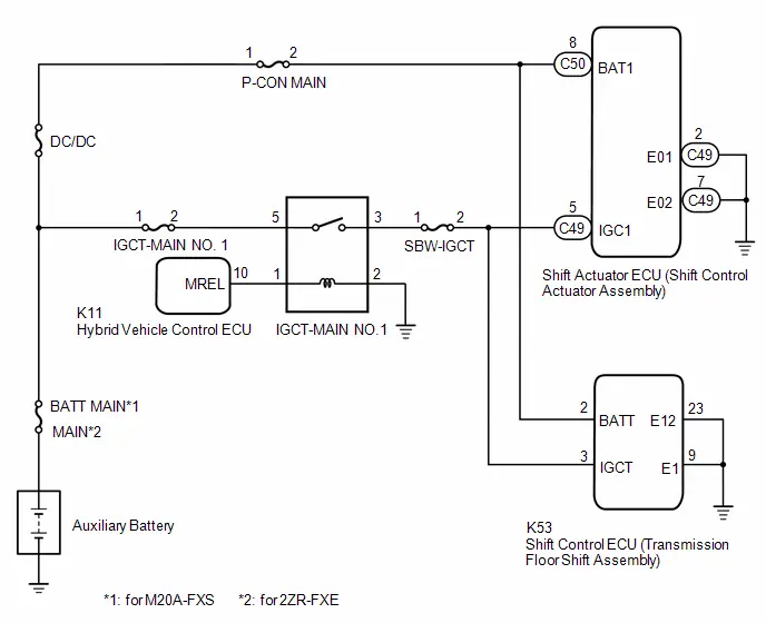
CAUTION / NOTICE / HINT
NOTICE:
- When removing or installing the shift control ECU or shift actuator
ECU, make sure there is no power supplied*1 when disconnecting or connecting
the connectors.
*1: Auxiliary battery, sub-battery, integrated capacitor, etc.
- When disconnecting a wire harness of any component connected to the supply power of the integrated capacitor or when removing the integrated capacitor, make sure to wait 5 minutes or more after turning the ignition switch off for self-diagnosis to complete and the voltage of the integrated capacitor to discharge.
- Before performing troubleshooting, check the fuses, connector connections and contact pressure of the relevant terminals for this circuit.
PROCEDURE
|
1. |
CHECK HARNESS AND CONNECTOR (IGC1 TERMINAL VOLTAGE) |
Pre-procedure1
(a) Disconnect the C49 shift actuator ECU (shift control actuator assembly) connector.
(b) Connect the cable to the negative (-) auxiliary battery terminal.
(c) Turn the ignition switch to ON.
Procedure1
(d) Measure the voltage according to the value(s) in the table below.
Standard Voltage:
 Click Location & Routing(C49) Click Connector(C49)
|
Tester Connection |
Switch Condition |
Specified Condition |
Result |
|---|---|---|---|
|
C49-5 (IGC1) - Body ground |
Ignition switch ON |
11 to 14 V |
V |
Post-procedure1
(e) Turn the ignition switch off.
(f) Disconnect the cable from the negative (-) auxiliary battery terminal.
(g) Reconnect the shift actuator ECU (shift control actuator assembly) connector.
| OK |
 |
REPLACE SHIFT ACTUATOR ECU (SHIFT CONTROL ACTUATOR ASSSEMBLY) |
|

|
2. |
INSPECT IGCT-MAIN NO. 1 RELAY |
Pre-procedure1
(a) Remove the IGCT-MAIN NO. 1 relay from the No. 1 engine room relay block and No. 1 junction block assembly.
Procedure1
|
(b) Measure the resistance according to the value(s) in the table below. Standard Resistance:
Result:
|
|

Post-procedure1
(c) Install the IGCT-MAIN NO. 1 relay to the No. 1 engine room relay block and No. 1 junction block assembly.
| OK |
 |
REPAIR OR REPLACE HARNESS OR CONNECTOR (IGCT POWER SUPPLY CIRCUIT) |
| NG |
 |
REPLACE IGCT-MAIN NO. 1 RELAY |
Gear Shift Control Module "A"/"B" IGCT-Scene Signal Compare Failure (P18A862)
DESCRIPTION
The shift actuator ECU activates when receiving an IGCT SCENE signal.
|
DTC No. |
Detection Item |
DTC Detection Condition |
Trouble Area |
MIL |
Warning Indicate |
DTC Output from |
Priority |
Note |
|---|---|---|---|---|---|---|---|---|
|
P18A862 |
Gear Shift Control Module "A"/"B" IGCT-Scene Signal Compare Failure |
When the ignition switch is ON (IG) and the BAT1 voltage is a certain value or more, a malfunction of the IGS1 terminal voltage is detected (1 trip detection logic) |
|
Does not come on |
Multi-information Display Error Message
|
Hybrid Control |
A |
SAE: P18A8 |
CONFIRMATION DRIVING PATTERN
HINT:
After repair has been completed, clear the DTC and then check that the Toyota Prius vehicle has returned to normal by performing the All Readiness check procedure.
- Turn the ignition switch to ON and wait for 1 minute or more.
WIRING DIAGRAM
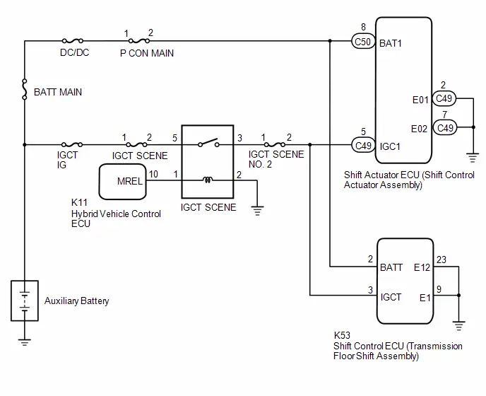
CAUTION / NOTICE / HINT
NOTICE:
- When removing or installing the shift control ECU or shift actuator
ECU, make sure there is no power supplied*1 when disconnecting or connecting
the connectors.
*1: Auxiliary battery, sub-battery, integrated capacitor, etc.
- When disconnecting a wire harness of any component connected to the supply power of the integrated capacitor or when removing the integrated capacitor, make sure to wait 5 minutes or more after turning the ignition switch off for self-diagnosis to complete and the voltage of the integrated capacitor to discharge.
- Before performing troubleshooting, check the fuses, connector connections and contact pressure of the relevant terminals for this circuit.
PROCEDURE
|
1. |
CHECK HARNESS AND CONNECTOR (IGS1 TERMINAL VOLTAGE) |
Pre-procedure1
(a) Disconnect the C49 shift actuator ECU (shift control actuator assembly) connector.
(b) Connect the cable to the negative (-) auxiliary battery terminal.
(c) Turn the ignition switch to ON.
Procedure1
(d) Measure the voltage according to the value(s) in the table below.
Standard Voltage:
 Click Location & Routing(C49) Click Connector(C49)
|
Tester Connection |
Switch Condition |
Specified Condition |
Result |
|---|---|---|---|
|
C49-5 (IGC1) - Body ground |
Ignition switch ON |
11 to 14 V |
V |
Post-procedure1
(e) Turn the ignition switch off.
(f) Disconnect the cable from the negative (-) auxiliary battery terminal.
(g) Reconnect the shift actuator ECU (shift control actuator assembly) connector.
| OK |
 |
REPLACE SHIFT CONTROL ACTUATOR ASSEMBLY (SHIFT ACTUATOR ECU) |
|

|
2. |
INSPECT IGCT SCENE RELAY |
Pre-procedure1
(a) Remove the IGCT SCENE relay from the No. 3 relay block.
Procedure1
|
(b) Measure the resistance according to the value(s) in the table below. Standard Resistance:
Result:
|
|
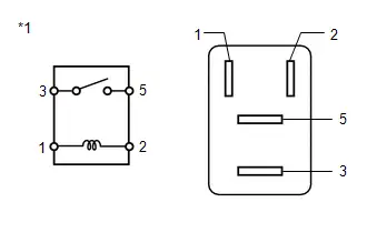
Post-procedure1
(c) Install the IGCT SCENE relay.
| OK |
 |
REPAIR OR REPLACE HARNESS OR CONNECTOR (IGC1 POWER SUPPLY CIRCUIT) |
| NG |
 |
REPLACE IGCT SCENE RELAY |
Gear Shift Control Module "B" EPBT Circuit Short to Battery (P18AF12)
DESCRIPTION
If the shift status cannot be changed from P to N due to a vehicle malfunction, towing using a tow truck, etc., is not possible.
Using a P position release tool, the shift actuator ECU sends an activation trigger (EPBT signal) to the shift actuator ECU to enable a shift state change from P to N. (for P position release tool compatible Toyota Prius vehicles)
|
DTC No. |
Detection Item |
DTC Detection Condition |
Trouble Area |
MIL |
Warning Indicate |
DTC Output from |
Priority |
Note |
|---|---|---|---|---|---|---|---|---|
|
P18AF12 |
Gear Shift Control Module "B" EPBT Circuit Short to Battery |
When the BAT1 voltage is a certain value or more and the shift actuator ECU is operating, a certain voltage is detected at the EPBT terminal. (1 trip detection logic) |
Shift actuator ECU (shift control actuator assembly) |
Does not come on |
Multi-information Display Error Message
|
Hybrid Control |
A |
SAE: P18B1 |
CONFIRMATION DRIVING PATTERN
HINT:
After repair has been completed, clear the DTC and then check that the Toyota Prius vehicle has returned to normal by performing the All Readiness check procedure.
Click here

- Turn the ignition switch to ON and wait for 1 minutes or more.
CAUTION / NOTICE / HINT
NOTICE:
- When removing or installing the shift control ECU or shift actuator
ECU, make sure there is no power supplied*1 when disconnecting or connecting
the connectors.
*1: Auxiliary battery, sub-battery, integrated capacitor, etc.
- When disconnecting a wire harness of any component connected to the supply power of the integrated capacitor or when removing the integrated capacitor, make sure to wait 5 minutes or more after turning the ignition switch off for self-diagnosis to complete and the voltage of the integrated capacitor to discharge.
- Before performing troubleshooting, check the fuses, connector connections and contact pressure of the relevant terminals for this circuit.
PROCEDURE
|
1. |
REPLACE SHIFT ACTUATOR ECU (SHIFT CONTROL ACTUATOR ASSSEMBLY) |
Click here

| NEXT |
 |
END |
Gear Shift Control Module "B" Motor Angle Sensor "A" Performance (P18B200)
DESCRIPTION
The shift actuator ECU monitors the ECU internal operation, and if a malfunction is detected, the hybrid vehicle control ECU stores a DTC.
|
DTC No. |
Detection Item |
DTC Detection Condition |
Trouble Area |
MIL |
Warning Indicate |
DTC Output from |
Priority |
Note |
|---|---|---|---|---|---|---|---|---|
|
P18B200 |
Gear Shift Control Module "B" Motor Angle Sensor "A" Performance |
When the BAT1 terminal voltage is a certain value or more, an abnormal motor rotation angle is continuously detected (1 trip detection logic) |
Shift actuator ECU (shift control actuator assembly) |
Does not come on |
Multi-information Display Error Message
|
Hybrid Control |
A |
SAE: P18B2 |
CONFIRMATION DRIVING PATTERN
HINT:
After repairs have been completed, clear the DTCs and then check that the Toyota Prius vehicle has returned to normal by performing the All Readiness check procedure.
Click here

- Turn the ignition switch to ON (READY).
- With the brake pedal depressed, perform a shift operation then change the shift state to N. (*1)
- Press the P position switch to change the shift state to P. (*2)
- Perform the above steps (*1 and *2) several times.
CAUTION / NOTICE / HINT
NOTICE:
- When removing or installing the shift control ECU and shift actuator
ECU, make sure there is no power supplied*1 when disconnecting or connecting
the connectors.
*1: Auxiliary battery, sub-battery, integrated capacitor, etc.
- When disconnecting a wire harness of any component connected to the supply power of the integrated capacitor or when removing the integrated capacitor, make sure to wait 5 minutes or more after turning the ignition switch off for self-diagnosis to complete and the voltage of the integrated capacitor to discharge.
- Before performing troubleshooting, check the fuses, connector connections and contact pressure of the relevant terminals for this circuit.
PROCEDURE
|
1. |
REPLACE SHIFT ACTUATOR ECU (SHIFT CONTROL ACTUATOR ASSSEMBLY) |
Click here

| NEXT |
 |
END |
Gear Shift Control Module "B" Motor Temperature Sensor "A" Circuit Voltage Out of Range (P18B31C)
DESCRIPTION
The shift actuator ECU monitors the ECU internal operation, and if a malfunction is detected, the hybrid vehicle control ECU stores a DTC.
|
DTC No. |
Detection Item |
DTC Detection Condition |
Trouble Area |
MIL |
Warning Indicate |
DTC Output from |
Priority |
Note |
|---|---|---|---|---|---|---|---|---|
|
P18B31C |
Gear Shift Control Module "B" Motor Temperature Sensor "A" Circuit Voltage Out of Range |
When the ignition switch is ON (IG) and the BAT1 voltage is a certain value or more, a malfunction of the system 1 microcomputer temperature sensor is detected. (1 trip detection logic) |
Shift actuator ECU (shift control actuator assembly) |
Does not come on |
Multi-information Display Error Message
|
Hybrid Control |
A |
SAE: P18B4 |
CONFIRMATION DRIVING PATTERN
HINT:
After repairs have been completed, clear the DTCs and then check that the Toyota Prius vehicle has returned to normal by performing the All Readiness check procedure.
Click here

- Turn the ignition switch to ON and wait for 1 minutes or more.
CAUTION / NOTICE / HINT
NOTICE:
- When removing or installing the shift control ECU or shift actuator
ECU, make sure there is no power supplied*1 when disconnecting or connecting
the connectors.
*1: Auxiliary battery, sub-battery, integrated capacitor, etc.
- When disconnecting a wire harness of any component connected to the supply power of the integrated capacitor or when removing the integrated capacitor, make sure to wait 5 minutes or more after turning the ignition switch off for self-diagnosis to complete and the voltage of the integrated capacitor to discharge.
- Before performing troubleshooting, check the fuses, connector connections and contact pressure of the relevant terminals for this circuit.
PROCEDURE
|
1. |
READ VALUE USING GTS (GEAR SHIFT CONTROL MODULE "B" CPU TEMPERATURE) |
Pre-procedure1
(a) Turn the ignition switch to ON.
Procedure1
(b) Read the Data List according to the display on the GTS.
Powertrain > Hybrid Control > Data List|
Tester Display |
|---|
|
Gear Shift Control Module "B" CPU Temperature |
|
Result |
Proceed to |
|---|---|
|
The value of Gear Shift Control Module "B" CPU Temperature is -44 °C or more, and 126 °C or less |
A |
|
None of the above conditions are met |
B |
HINT:
- -44°C=-47°F
- 126°C=258°F
Post-procedure1
(c) Turn the ignition switch off.
| B |
 |
REPLACE SHIFT ACTUATOR ECU (SHIFT CONTROL ACTUATOR ASSSEMBLY) |
|

|
2. |
CLEAR DTC |
Pre-procedure1
(a) Turn the ignition switch to ON.
Procedure1
(b) Clear the DTCs.
Powertrain > Hybrid Control > Clear DTCsPost-procedure1
(c) Turn the ignition switch off.
(d) Leave the Toyota Prius vehicle as is for 60 seconds or more.
NOTICE:
- Do not connect the GTS.
- Do not depress the brake pedal.
- Do not open/close any of the doors.
|

|
3. |
CHECK DTC OUTPUT (PERFORM A REPRODUCTION TEST) |
Pre-procedure1
(a) Turn the ignition switch to ON and wait for 1 minutes or more.
Procedure1
(b) Check if DTCs are output.
Powertrain > Hybrid Control > Trouble Codes|
Result |
Proceed to |
|---|---|
|
P18B31C is not output |
A |
|
P18B31C is output |
B |
Post-procedure1
(c) Turn the ignition switch off.
| A |
 |
END |
| B |
 |
REPLACE SHIFT ACTUATOR ECU (SHIFT CONTROL ACTUATOR ASSSEMBLY) |
Gear Shift Actuator "A" Phase U-V-W Current Sensor Signal Compare Failure (P18B562)
DESCRIPTION
The shift actuator ECU monitors the ECU internal operation, and if a malfunction is detected, the hybrid vehicle control ECU stores a DTC.
|
DTC No. |
Detection Item |
DTC Detection Condition |
Trouble Area |
MIL |
Warning Indicate |
DTC Output from |
Priority |
Note |
|---|---|---|---|---|---|---|---|---|
|
P18B562 |
Gear Shift Actuator "A" Phase U-V-W Current Sensor Signal Compare Failure |
When the BAT1 terminal voltage is a certain value or more, the total value of the actuator motor current sensor for phase U, V and W exceeds a certain value continuously (1 trip detection logic) |
Shift actuator ECU (shift control actuator assembly) |
Does not come on |
Multi-information Display Error Message
|
Hybrid Control |
A |
SAE: P18B5 |
CONFIRMATION DRIVING PATTERN
HINT:
After repairs have been completed, clear the DTCs and then check that the Toyota Prius vehicle has returned to normal by performing the All Readiness check procedure.
Click here

- Turn the ignition switch to ON (READY).
- With the brake pedal depressed, perform a shift operation then change the shift state to N.
- Press the P position switch to change the shift state to P.
CAUTION / NOTICE / HINT
NOTICE:
- When removing or installing the shift control ECU and shift actuator
ECU, make sure there is no power supplied*1 when disconnecting or connecting
the connectors.
*1: Auxiliary battery, sub-battery, integrated capacitor, etc.
- When disconnecting a wire harness of any component connected to the supply power of the integrated capacitor or when removing the integrated capacitor, make sure to wait 5 minutes or more after turning the ignition switch off for self-diagnosis to complete and the voltage of the integrated capacitor to discharge.
- Before performing troubleshooting, check the fuses, connector connections and contact pressure of the relevant terminals for this circuit.
PROCEDURE
|
1. |
REPLACE SHIFT ACTUATOR ECU (SHIFT CONTROL ACTUATOR ASSSEMBLY) |
Click here

| NEXT |
 |
END |
Gear Lever Position Sensor "A" Signal Plausibility Failure (P2E0064,P2E0464,P2E0864)
DESCRIPTION
The shift control ECU and 3 shift sensors are built into the transmission floor shift assembly. The shift control ECU monitors the angle information of the shift sensors and power supply voltage for sensors.
|
DTC No. |
Detection Item |
DTC Detection Condition |
Trouble Area |
MIL |
Warning Indicate |
DTC Output from |
Priority |
Note |
|---|---|---|---|---|---|---|---|---|
|
P2E0064 |
Gear Lever Position Sensor "A" Signal Plausibility Failure |
When the auxiliary battery voltage is a certain value or more, any of
the following is met:
(1 trip detection logic) |
Shift control ECU (transmission floor shift assembly) |
Does not come on |
Multi-information Display Error Message
|
Hybrid Control |
A |
SAE: P2E01 |
|
P2E0464 |
Gear Lever Position Sensor "B" Signal Plausibility Failure |
When the auxiliary battery voltage is a certain value or more, any of
the following is met:
(1 trip detection logic) |
Shift control ECU (transmission floor shift assembly) |
Does not come on |
Multi-information Display Error Message
|
Hybrid Control |
A |
SAE: P2E05 |
|
P2E0864 |
Gear Lever Position Sensor "C" Signal Plausibility Failure |
When the auxiliary battery voltage is a certain value or more, any of
the following is met:
(1 trip detection logic) |
Shift control ECU (transmission floor shift assembly) |
Does not come on |
Multi-information Display Error Message
|
Hybrid Control |
A |
SAE: P2E09 |
CONFIRMATION DRIVING PATTERN
HINT:
After repairs have been completed, clear the DTCs and then check that the Toyota Prius vehicle has returned to normal by performing the All Readiness check procedure.
Click here

- Turn the ignition switch to ON (READY) and wait for 1 minute or more.
- Turn all switches off and turn the ignition switch off.
- Disconnect the GTS.
- Wait for 5 minutes or more with the door lock locked.
HINT:
- Once the door lock is locked, keep the electrical key transmitter sub-assembly (electrical key) 3 m (9.84 ft.) or more away from the Toyota Prius vehicle.
- Because the system will not sleep while any door and/or the hood is open, take steps such as securing the courtesy switch to make the system recognize the doors and hood as closed when carrying out the operation.
- If the vehicle is equipped with a power back door, the system will not sleep if the back door is not closed. Ensure that the back door is closed before carrying out the operation.
- Turn the ignition switch to ON (READY) and wait for 1 minute or more.
CAUTION / NOTICE / HINT
NOTICE:
- When removing or installing the shift control ECU or shift actuator
ECU, make sure there is no power supplied*1 when disconnecting or connecting
the connectors.
*1: Auxiliary battery, sub-battery, integrated capacitor, etc.
- When disconnecting a wire harness of any component connected to the supply power of the integrated capacitor or when removing the integrated capacitor, make sure to wait 5 minutes or more after turning the ignition switch off for self-diagnosis to complete and the voltage of the integrated capacitor to discharge.
- Before performing troubleshooting, check the fuses, connector connections and contact pressure of the relevant terminals for this circuit.
PROCEDURE
|
1. |
CHECK DTC OUTPUT (HEALTH CHECK) |
Pre-procedure1
(a) Turn the ignition switch to ON.
Procedure1
(b) Using the GTS, perform a Health Check.
(c) Check for DTCs.
Post-procedure1
(d) Turn the ignition switch off.
|

|
2. |
CLEAR DTC |
Pre-procedure1
(a) Turn the ignition switch to ON.
Procedure1
(b) Clear the DTCs.
Powertrain > Hybrid Control > Clear DTCsPost-procedure1
(c) Turn the ignition switch off.
(d) Disconnect the GTS.
(e) Leave the Toyota Prius vehicle as is for 60 seconds or more.
NOTICE:
- Do not connect the GTS.
- Do not depress the brake pedal.
- Do not open/close any of the doors.
|

|
3. |
CHECK DTC OUTPUT (PERFORM A REPRODUCTION TEST) |
Pre-procedure1
(a) Turn the ignition switch to ON (READY) and wait for 1 minute or more.
(b) Turn all switches off and turn the ignition switch off.
(c) Disconnect the GTS.
(d) Wait for 5 minutes or more with the door lock locked.
HINT:
- Once the door lock is locked, keep the electrical key transmitter sub-assembly (electrical key) 3 m (9.84 ft.) or more away from the Toyota Prius vehicle.
- Because the system will not sleep while any door and/or the hood is open, take steps such as securing the courtesy switch to make the system recognize the doors and hood as closed when carrying out the operation.
- If the vehicle is equipped with a power back door, the system will not sleep if the back door is not closed. Ensure that the back door is closed before carrying out the operation.
(e) Turn the ignition switch to ON (READY) and wait for 1 minute or more.
Procedure1
(f) Check for DTCs.
Powertrain > Hybrid Control > Trouble Codes|
Result |
Proceed to |
|---|---|
|
Only P2E0064, P2E0464 or P2E0864 is output |
A |
|
P2E0064, P2E0464 or P2E0864 and other DTCs are output |
B |
|
DTCs are not output |
C |
Post-procedure1
(g) Turn the ignition switch off.
| A |
 |
REPLACE SHIFT CONTROL ECU (TRANSMISSION FLOOR SHIFT ASSEMBLY) |
| B |
 |
GO TO DTC CHART |
| C |
 |
CHECK FOR INTERMITTENT PROBLEMS Click here
Click here
|


Lost Communication with Body Control Module (Sub) Missing Message (U014000,...,U117000)
DESCRIPTION
The shift control ECU receives and sends various signals to and from the main body ECU, combination meter, hybrid vehicle control ECU, smart key ECU assembly (certification ECU) and skid control ECU via CAN communication.
|
DTC No. |
Detection Item |
DTC Detection Condition |
Trouble Area |
MIL |
Warning Indicate |
DTC Output from |
Priority |
Note |
|---|---|---|---|---|---|---|---|---|
|
U014000 |
Lost Communication with Body Control Module (Sub) Missing Message |
When the ignition switch is ON (IG) and the auxiliary battery voltage is a certain value or more, a CAN communication malfunction with the main body ECU is continuously detected (1 trip detection logic) |
CAN communication system |
Does not come on |
Multi-information Display Error Message
|
Hybrid Control |
B |
SAE: U0140 |
|
U015586 |
Lost Communication with Instrument Panel Cluster (IPC) Control Module Signal (some circuit quantity, reported via serial data) Invalid |
When the ignition switch is ON (IG) and the auxiliary battery voltage is a certain value or more, a CAN communication malfunction with the combination meter is continuously detected (1 trip detection logic) |
CAN communication system |
Does not come on |
Multi-information Display Error Message
|
Hybrid Control |
B |
SAE: U0155 |
|
U029300 |
Lost Communication with Hybrid/EV Powertrain Control Module from Gear Shift Control Module "A" |
When the ignition switch is ON (IG) and the auxiliary battery voltage is a certain value or more, a CAN communication malfunction with the hybrid Toyota Prius vehicle control ECU is continuously detected (1 trip detection logic) |
CAN communication system |
Does not come on |
Multi-information Display Error Message
|
Hybrid Control |
B |
SAE: U0293 |
|
U110700 |
Lost Communication with Power Management Module (Gear Shift Control Module "A") |
When the ignition switch is ON (IG) and the auxiliary battery voltage is a certain value or more, a CAN communication malfunction with the smart key ECU assembly (certification ECU) is continuously detected (1 trip detection logic) |
CAN communication system |
Does not come on |
Multi-information Display Error Message
|
Hybrid Control |
B |
SAE: U1107 |
|
U114F00 |
Lost Communication with Power Integration Module (System 2) Missing Message |
When the ignition switch is ON (IG) and the auxiliary battery voltage is a certain value or more, a CAN communication malfunction with the main body ECU (power integration) is continuously detected (1 trip detection logic) |
CAN communication system |
Does not come on |
Multi-information Display Error Message
|
Hybrid Control |
B |
SAE: U114F |
|
U117000 |
Lost Communication with Brake System Control Module (Gear Shift Control Module "A") |
When the ignition switch is ON (IG) and the auxiliary battery voltage is a certain value or more, a CAN communication malfunction with the skid control ECU is continuously detected (1 trip detection logic) |
CAN communication system |
Does not come on |
Multi-information Display Error Message
|
Hybrid Control |
B |
SAE: U1170 |
CONFIRMATION DRIVING PATTERN
HINT:
After repair has been completed, clear the DTC and then check that the Toyota Prius vehicle has returned to normal by performing the All Readiness check procedure.
Click here

- Turn the ignition switch to ON and wait for 1 minute or more.
CAUTION / NOTICE / HINT
NOTICE:
- When removing or installing the shift control ECU or shift actuator
ECU, make sure there is no power supplied*1 when disconnecting or connecting
the connectors.
*1: Auxiliary battery, sub-battery, integrated capacitor, etc.
- When disconnecting a wire harness of any component connected to the supply power of the integrated capacitor or when removing the integrated capacitor, make sure to wait 5 minutes or more after turning the ignition switch off for self-diagnosis to complete and the voltage of the integrated capacitor to discharge.
- Before performing troubleshooting, check the fuses, connector connections and contact pressure of the relevant terminals for this circuit.
PROCEDURE
|
1. |
CHECK DTC OUTPUT (HEALTH CHECK) |
Pre-procedure1
(a) Turn the ignition switch to ON.
Procedure1
(b) Using the GTS, perform a Health Check.
Post-procedure1
(c) Turn the ignition switch off.
| NEXT |
 |
GO TO CAN COMMUNICATION SYSTEM for HEV Model:
for PHEV Model:
|


Lost Communication with Gear Shift Control Module "B" (System 2) Missing Message (U029100)
DESCRIPTION
The shift control ECU receives or sends a signal to and from the shift actuator ECU via CAN communication.
|
DTC No. |
Detection Item |
DTC Detection Condition |
Trouble Area |
MIL |
Warning Indicate |
DTC Output from |
Priority |
Note |
|---|---|---|---|---|---|---|---|---|
|
U029100 |
Lost Communication with Gear Shift Control Module "B" (System 2) Missing Message |
When the ignition switch is ON (IG) and the auxiliary battery voltage is a certain value or more, a CAN communication malfunction with the shift actuator ECU is continuously detected (1 trip detection logic) |
|
Does not come on |
Multi-information Display Error Message
|
Hybrid Control |
B |
SAE: U0291 |
CONFIRMATION DRIVING PATTERN
HINT:
After repair has been completed, clear the DTC and then check that the Toyota Prius vehicle has returned to normal by performing the All Readiness check procedure.
Click here

- Turn the ignition switch to ON and wait for 1 minute or more.
WIRING DIAGRAM
for HEV Model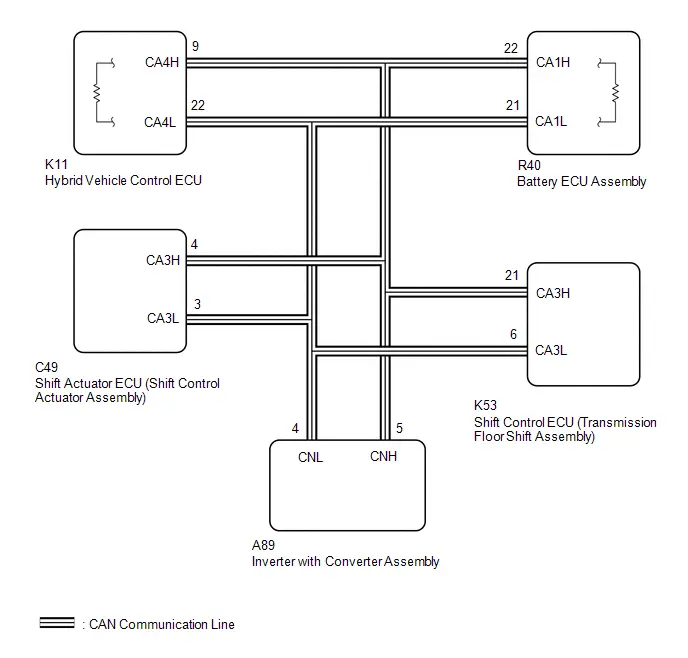 for PHEV Model
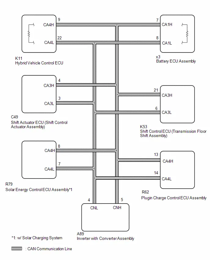
CAUTION / NOTICE / HINT
NOTICE:
- When removing or installing the shift control ECU or shift actuator
ECU, make sure there is no power supplied*1 when disconnecting or connecting
the connectors.
*1: Auxiliary battery, sub-battery, integrated capacitor, etc.
- When disconnecting a wire harness of any component connected to the supply power of the integrated capacitor or when removing the integrated capacitor, make sure to wait 5 minutes or more after turning the ignition switch off for self-diagnosis to complete and the voltage of the integrated capacitor to discharge.
- Before performing troubleshooting, check the fuses, connector connections and contact pressure of the relevant terminals for this circuit.
PROCEDURE
|
1. |
CHECK DTC OUTPUT (HEALTH CHECK) |
Pre-procedure1
(a) Turn the ignition switch to ON.
Procedure1
(b) Using the GTS, perform a Health Check.
|
Result |
Proceed to |
|---|---|
|
U029100 only is output |
A |
|
U029100 and other DTCs are output |
B |
Post-procedure1
(c) Turn the ignition switch off.
| B |
 |
GO TO DTC CHART |
|

|
2. |
CHECK FOR SHORT IN CAN BUS LINE (ECU CONNECTED) |
Pre-procedure1
(a) Disconnect the cable from the negative (-) auxiliary battery terminal.
Procedure1
|
(b) Measure the resistance according to the value(s) in the table below. Standard Resistance (Check for Short):  Click Location & Routing(K53) Click
Connector(K53) Click Location & Routing(K53) Click
Connector(K53)
Result:
|
|
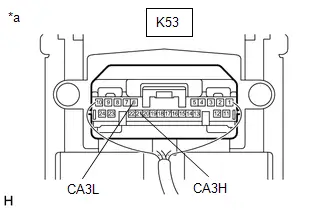
Post-procedure1
(c) Connect the cable to the negative (-) auxiliary battery terminal.
| NG |
 |
GO TO STEP 5 |
|

|
3. |
CHECK FOR OPEN AND SHORT TO OTHER TERMINALS IN CAN BUS LINE (SHIFT CONTROL ECU - SHIFT ACTUATOR ECU) |
Pre-procedure1
(a) Disconnect the cable from the negative (-) auxiliary battery terminal.
(b) Disconnect the C49 shift actuator ECU (shift control actuator assembly) connector.
Procedure1
(c) Measure the resistance according to the value(s) in the table below.
Standard Resistance (Check for Open):
 Click Location & Routing(C49) Click Connector(C49)
|
Tester Connection |
Condition |
Specified Condition |
Result |
|---|---|---|---|
|
C49-4 (CA3H) - C49-3 (CA3L) |
Cable from negative (-) auxiliary battery terminal disconnected |
54 to 69 Ω |
Ω |
Post-procedure1
(d) Connect the shift actuator ECU (shift control actuator assembly) connector.
(e) Connect the cable to the negative (-) auxiliary battery terminal.
| OK |
 |
REPLACE SHIFT ACTUATOR ECU (SHIFT CONTROL ACTUATOR ASSSEMBLY) |
|

|
4. |
CHECK HARNESS AND CONNECTOR (SHIFT CONTROL ECU - SHIFT ACTUATOR ECU) |
Pre-procedure1
(a) Disconnect the K53 shift control ECU (transmission floor shift assembly) connector.
(b) Disconnect the C49 shift actuator ECU (shift control actuator assembly) connector.
(c) Disconnect the K11 hybrid Toyota Prius vehicle control ECU connector.
(d) Disconnect the R40 battery ECU assembly connector. (for HEV model)
(e) Disconnect the x3 battery ECU assembly connector. (for PHEV model)
(f) Connect the SST. (for PHEV model)
HINT:
Click here

(g) Disconnect the A89 inverter with converter assembly connector.
(h) Disconnect the R62 plugin charge control ECU assembly connector. (for PHEV model)
(i) Disconnect the R79 solar energy control ECU assembly connector. (w/ Solar charging system)
Procedure1
(j) Measure the resistance according to the value(s) in the table below.
Standard Resistance:
 Click Location & Routing(K53,C49) Click
Connector(K53) Click Connector(C49)
Click Location & Routing(K53,C49) Click
Connector(K53) Click Connector(C49)
|
Tester Connection |
Condition |
Specified Condition |
Result |
|---|---|---|---|
|
K53-21 (CA3H) - C49-4 (CA3H) |
Always |
Below 1 Ω |
Ω |
|
K53-6 (CA3L) - C49-3 (CA3L) |
Always |
Below 1 Ω |
Ω |
|
C49-4 (CA3H) - C49-3 (CA3L) |
Always |
1 MΩ or higher |
MΩ |
|
K53-21 (CA3H) - K53-6 (CA3L) |
Always |
1 MΩ or higher |
MΩ |
Post-procedure1
(k) Connect the Solar energy control ECU assembly connector. (w/ Solar charging system)
(l) Connect the Plugin charge control ECU assembly connector. (for PHEV model)
(m) Connect the inverter with converter assembly connector.
(n) Disconnect the SST. (for PHEV model)
(o) Connect the battery ECU assembly connector. (for PHEV model)
(p) Connect the battery ECU assembly connector. (for HEV model)
(q) Connect the hybrid Toyota Prius vehicle control ECU connector.
(r) Connect the shift actuator ECU (shift control actuator assembly) connector.
(s) Connect the shift control ECU (transmission floor shift assembly) connector.
| OK |
 |
GO TO CAN COMMUNICATION SYSTEM for HEV Model:
for PHEV Model:
|


| NG |
 |
REPAIR OR REPLACE HARNESS OR CONNECTOR IN CAN BUS LINE (SHIFT CONTROL ECU - SHIFT ACTUATOR ECU) |
|
5. |
CHECK FOR SHORT TO GROUND IN CAN BUS LINE (SHIFT ACTUATOR ECU DISCONNECTED) |
Pre-procedure1
(a) Disconnect the cable from the negative (-) auxiliary battery terminal.
(b) Disconnect the C49 shift actuator ECU (shift control actuator assembly) connectors.
Procedure1
|
(c) Measure the resistance according to the value(s) in the table below. Standard Resistance:  Click Location & Routing(K53) Click
Connector(K53) Click Location & Routing(K53) Click
Connector(K53)
Result:
|
|

Post-procedure1
(d) Reconnect the shift actuator ECU (shift control actuator assembly) connector.
(e) Connect the cable to the negative (-) auxiliary battery terminal.
| OK |
 |
REPLACE SHIFT ACTUATOR ECU (SHIFT CONTROL ACTUATOR ASSSEMBLY) |
|

|
6. |
CHECK FOR SHORT TO GROUND IN CAN BUS LINE (SHIFT CONTROL ECU DISCONNECTED) |
Pre-procedure1
(a) Disconnect the cable from the negative (-) auxiliary battery terminal.
(b) Disconnect the K53 shift control ECU (transmission floor shift assembly) connector.
Procedure1
(c) Measure the resistance according to the value(s) in the table below.
Standard Resistance:
 Click Location & Routing(K53) Click Connector(K53)
|
Tester Connection |
Condition |
Specified Condition |
Result |
|---|---|---|---|
|
K53-21 (CA3H) or K53-6 (CA3L) - Body ground |
Cable from negative (-) auxiliary battery terminal disconnected |
200 Ω or higher |
Ω |
Post-procedure1
(d) Reconnect the shift control ECU (transmission floor shift assembly) connector.
(e) Connect the cable to the negative (-) auxiliary battery terminal.
| OK |
 |
REPLACE SHIFT CONTROL ECU (TRANSMISSION FLOOR SHIFT ASSEMBLY) |
| NG |
 |
REPAIR OR REPLACE HARNESS OR CONNECTOR IN CAN BUS LINE (SHIFT CONTROL ECU - SHIFT ACTUATOR ECU) |
ECU Power Source Circuit
DESCRIPTION
If the supply power to each ECU is discontinued due to a malfunction of the auxiliary battery power supply, the electronic shift lever system does not operate. Make sure to inspect the power supply system of the auxiliary battery for each ECU.
WIRING DIAGRAM
for HEV Model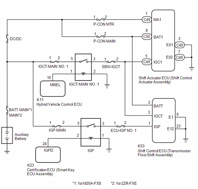 for PHEV Model
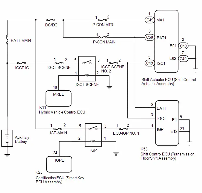
CAUTION / NOTICE / HINT
NOTICE:
- When removing or installing the shift control ECU or shift actuator
ECU, make sure there is no power supplied*1 when disconnecting or connecting
the connectors.
*1: Auxiliary battery, sub-battery, integrated capacitor, etc.
- When disconnecting a wire harness of any component connected to the supply power of the integrated capacitor or when removing the integrated capacitor, make sure to wait 5 minutes or more after turning the ignition switch off for self-diagnosis to complete and the voltage of the integrated capacitor to discharge.
- Before performing troubleshooting, check the fuses, connector connections and contact pressure of the relevant terminals for this circuit.
PROCEDURE
|
1. |
CHECK HARNESS AND CONNECTOR (BATT TERMINAL VOLTAGE) |
|
(a) Measure the voltage according to the value(s) in the table below. Standard Voltage:  Click Location & Routing(K53) Click
Connector(K53) Click Location & Routing(K53) Click
Connector(K53)
|
|
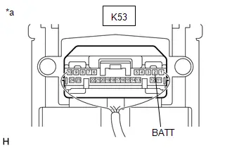
| NG |
 |
GO TO STEP 7 |
|

|
2. |
CHECK HARNESS AND CONNECTOR (IGCT, IGP TERMINAL VOLTAGE) |
(a) Turn the ignition switch to ON.
|
(b) Measure the voltage according to the value(s) in the table below. Standard Voltage:  Click Location & Routing(K53) Click
Connector(K53) Click Location & Routing(K53) Click
Connector(K53)
|
|
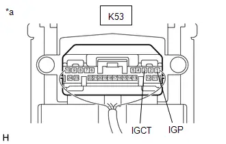
(c) Turn the Ignition switch off.
| NG |
 |
GO TO STEP 8 |
|

|
3. |
CHECK HARNESS AND CONNECTOR (SHIFT CONTROL ECU - BODY GROUND) |
(a) Disconnect the K53 shift control ECU (transmission floor shift assembly) connector.
(b) Measure the resistance according to the value(s) in the table below.
Standard Resistance:
 Click Location & Routing(K53) Click Connector(K53)
|
Tester Connection |
Condition |
Specified Condition |
|---|---|---|
|
K53-9 (E1) - Body ground |
Always |
Below 1 Ω |
|
K53-23 (E12) - Body ground |
Always |
Below 1 Ω |
(c) Reconnect the shift control ECU (transmission floor shift assembly) connector.
| NG |
 |
REPAIR OR REPLACE HARNESS OR CONNECTOR (SHIFT CONTROL ECU - BODY GROUND) |
|

|
4. |
CHECK HARNESS AND CONNECTOR (MA1, BAT1 TERMINAL VOLTAGE) |
(a) Disconnect the C49 and C50 shift actuator ECU (shift control actuator assembly) connectors.
(b) Measure the voltage according to the value(s) in the table below.
Standard Voltage:
 Click Location & Routing(C49,C50) Click
Connector(C49) Click Connector(C50)
Click Location & Routing(C49,C50) Click
Connector(C49) Click Connector(C50)
|
Tester Connection |
Condition |
Specified Condition |
|---|---|---|
|
C49-1 (MA1) - Body ground |
Ignition switch off |
11 to 14 V |
|
C50-8 (BAT1) - Body ground |
Ignition switch off |
11 to 14 V |
(c) Reconnect the shift actuator ECU (shift control actuator assembly) connector.
| NG |
 |
GO TO STEP 9 |
|

|
5. |
CHECK HARNESS AND CONNECTOR (IGC1 TERMINAL VOLTAGE) |
(a) Disconnect the C49 shift actuator ECU (shift control actuator assembly) connector.
(b) Turn the ignition switch to ON.
NOTICE:
If the ignition switch is turned to ON with the connector disconnected, other DTCs will be stored. Be sure to clear the DTCs after the inspection.
(c) Measure the voltage according to the value(s) in the table below.
Standard Voltage:
 Click Location & Routing(C49) Click Connector(C49)
|
Tester Connection |
Condition |
Specified Condition |
|---|---|---|
|
C49-5 (IGC1) - Body ground |
Ignition switch ON |
11 to 14 V |
(d) Turn the Ignition switch off.
(e) Reconnect the shift actuator ECU (shift control actuator assembly) connector.
| NG |
 |
REPAIR OR REPLACE HARNESS OR CONNECTOR (IGCT-MAIN NO. 1 RELAY CIRCUIT) |
|

|
6. |
CHECK HARNESS AND CONNECTOR (SHIFT ACTUATOR ECU - BODY GROUND) |
(a) Disconnect the C49 shift actuator ECU (shift control actuator assembly) connector.
(b) Measure the resistance according to the value(s) in the table below.
Standard Resistance:
 Click Location & Routing(C49) Click Connector(C49)
|
Tester Connection |
Condition |
Specified Condition |
|---|---|---|
|
C49-2 (E01) - Body ground |
Always |
Below 1 Ω |
|
C49-7 (E02) - Body ground |
Always |
Below 1 Ω |
(c) Reconnect the shift actuator ECU (shift control actuator assembly) connector.
| OK |
 |
GO TO PROBLEM SYMPTOMS TABLE |
| NG |
 |
REPAIR OR REPLACE HARNESS OR CONNECTOR (SHIFT ACTUATOR ECU - BODY GROUND) |
|
7. |
CHECK HARNESS AND CONNECTOR (SHIFT CONTROL ECU - NO. 1 ENGINE ROOM RELAY BLOCK AND NO. 1 JUNCTION BLOCK ASSEMBLY) |
(a) Remove the P-CON MAIN fuse from the No. 1 engine room relay block and No. 1 junction block assembly.
(b) Disconnect the C50 shift actuator ECU (shift control actuator assembly) connector.
(c) Disconnect the K53 shift control ECU (transmission floor shift assembly) connector.
(d) Measure the resistance according to the value(s) in the table below.
Standard Resistance:
 Click Location & Routing(K53) Click Connector(K53)
|
Tester Connection |
Condition |
Specified Condition |
|---|---|---|
|
K53-2 (BATT) - 2 (P-CON MAIN fuse holder) |
Always |
Below 1 Ω |
|
K53-2 (BATT) or 2 (P-CON MAIN fuse holder) - Body ground and other terminals |
Always |
10 kΩ or higher |
(e) Reconnect the shift control ECU (transmission floor shift assembly) connector.
(f) Reconnect the shift actuator ECU (shift control actuator assembly) connector.
(g) Install the P-CON MAIN fuse.
| OK |
 |
REPAIR OR REPLACE HARNESS OR CONNECTOR (AUXILIARY BATTERY - NO. 1 ENGINE ROOM RELAY BLOCK AND NO. 1 JUNCTION BLOCK ASSEMBLY) |
| NG |
 |
REPAIR OR REPLACE HARNESS OR CONNECTOR (SHIFT CONTROL ECU - NO. 1 ENGINE ROOM RELAY BLOCK AND NO. 1 JUNCTION BLOCK ASSEMBLY) |
|
8. |
CHECK HARNESS AND CONNECTOR (SHIFT CONTROL ECU - NO. 1 ENGINE ROOM RELAY BLOCK AND NO. 1 JUNCTION BLOCK ASSEMBLY) |
(a) Remove the SBW-IGCT fuse from the No. 1 engine room relay block and No. 1 junction block assembly. (for HEV model)
(b) Remove the IGCT SCENE NO. 2 fuse from the No. 1 engine room relay block and No. 1 junction block assembly. (for PHEV model)
(c) Remove the ECU-IGP NO. 1 fuse from the No. 1 engine room relay block and No. 1 junction block assembly.
(d) Disconnect the C49 shift actuator ECU (shift control actuator assembly) connector.
(e) Disconnect the K53 shift control ECU (transmission floor shift assembly) connector.
(f) Measure the resistance according to the value(s) in the table below.
Standard Resistance:
 Click Location & Routing(K53) Click Connector(K53)
|
Tester Connection |
Condition |
Specified Condition |
|---|---|---|
|
K53-3 (IGCT) - 2 (SBW-IGCT fuse holder) |
Always |
Below 1 Ω |
|
K53-1 (IGP) - 2 (ECU-IGP NO. 1 fuse holder) |
Always |
Below 1 Ω |
|
K53-3 (IGCT) or 2 (SBW-IGCT fuse holder) - Body ground and other terminals |
Always |
10 kΩ or higher |
|
K53-1 (IGP) or 2 (ECU-IGP NO. 1 fuse holder) - Body ground and other terminals |
Always |
10 kΩ or higher |
(g) Reconnect the shift control ECU (transmission floor shift assembly) connector.
(h) Reconnect the shift actuator ECU (shift control actuator assembly) connector.
(i) Install the ECU-IGP NO. 1 fuse.
(j) Install the IGCT SCENE NO. 2 fuse. (for PHEV model)
(k) Install the SBW-IGCT fuse. (for HEV model)
| OK |
 |
REPAIR OR REPLACE HARNESS OR CONNECTOR (IGCT-MAIN NO. 1 RELAY POWER SUPPLY, IGP RELAY POWER SUPPLY) |
| NG |
 |
REPAIR OR REPLACE HARNESS OR CONNECTOR (SHIFT CONTROL ECU - NO. 1 ENGINE ROOM RELAY BLOCK AND NO. 1 JUNCTION BLOCK ASSEMBLY) |
|
9. |
CHECK HARNESS AND CONNECTOR (SHIFT ACTUATOR ECU - NO. 1 ENGINE ROOM RELAY BLOCK AND NO. 1 JUNCTION BLOCK ASSEMBLY) |
(a) Remove the P-CON MTR fuse from the No. 1 engine room relay block and No. 1 junction block assembly.
(b) Remove the P-CON MAIN fuse from the No. 1 engine room relay block and No. 1 junction block assembly.
(c) Disconnect the K53 shift control ECU (transmission floor shift assembly) connector.
(d) Disconnect the C49 and C50 shift actuator ECU (shift control actuator assembly) connectors.
(e) Measure the resistance according to the value(s) in the table below.
Standard Resistance:
 Click Location & Routing(C49,C50) Click
Connector(C49) Click Connector(C50)
Click Location & Routing(C49,C50) Click
Connector(C49) Click Connector(C50)
|
Tester Connection |
Condition |
Specified Condition |
|---|---|---|
|
C49-1 (MA1) - 2 (P-CON MTR fuse holder) |
Always |
Below 1 Ω |
|
C50-8 (BAT1) - 2 (P-CON MAIN fuse holder) |
Always |
Below 1 Ω |
|
C49-1 (MA1) or 2 (P-CON MTR fuse holder) - Body ground and other terminals |
Always |
10 kΩ or higher |
|
C50-8 (BAT1) or 2 (P-CON MAIN fuse holder) - Body ground and other terminals |
Always |
10 kΩ or higher |
(f) Reconnect the shift actuator ECU (shift control actuator assembly) connector.
(g) Reconnect the shift control ECU (transmission floor shift assembly) connector.
(h) Install the P-CON MAIN fuse.
(i) Install the P-CON MTR fuse.
| OK |
 |
REPAIR OR REPLACE HARNESS OR CONNECTOR (AUXILIARY BATTERY - NO. 1 ENGINE ROOM RELAY BLOCK AND NO. 1 JUNCTION BLOCK ASSEMBLY) |
| NG |
 |
REPAIR OR REPLACE HARNESS OR CONNECTOR (SHIFT ACTUATOR ECU - NO. 1 ENGINE ROOM RELAY BLOCK AND NO. 1 JUNCTION BLOCK ASSEMBLY) |

Toyota Prius (XW60) 2023-2026 Service Manual
Electronic Shift Lever System
- Precaution
- Parts Location
- System Diagram
- How To Proceed With Troubleshooting
- Utility
- Problem Symptoms Table
- Terminals Of Ecu
- Freeze Frame Data
- Fail-safe Chart
- Data List / Active Test
- VEHICLE CONTROL HISTORY (RoB)
- Park/Neutral Switch Circuit Short to Ground (P085011,P085015)
- Gear Shift Control Module "A" System Internal Failure (P085D04)
- Gear Shift Control Module "A" Unexpected Operation (P085D94)
- Gear Lever Position Sensor Signal Compare Failure (P08A662)
- Gear Shift Position Circuit "A" Range/Performance Signal Cross Coupled (P09142B)
- Fail Safe Signal (Gear Shift Control Module "B" to "A") No Signal (P175231)
- Lost Communication with Gear Shift Control Module "B" (Local-CAN) Missing Message (P175387)
- Gear Shift Control Module "A" System Voltage Low (P1761A2)
- Sub Battery Module System Voltage Low (P1765A2)
- Gear Shift Control Module "A" A/D Processing Performance (P176900)
- IG2 Signal (Gear Shift Control Module "A") Circuit Short to Auxiliary Battery (P176D12)
- Gear Shift Control Module "B" System Voltage Low (P1771A2)
- Sub Battery Module (Gear Shift Control Module "B") System Voltage Low (P1775A2)
- Gear Shift Control Module Backup Power Supply Internal Electronic Failure (P177949)
- Lost Communication with Gear Shift Control Module Backup Power Supply Missing Message (P177A87)
- Lost Communication with Gear Shift Control Module "A" from "B" Missing Message (P178987)
- Gear Shift Control Module "B" Wake-up Circuit Short to Ground or Open (P178A14)
- Gear Shift Actuator "A" Supply Voltage "A" Circuit Short to Ground or Open (P179014)
- Gear Shift Actuator "A" Supply Voltage "B" Circuit Short to Ground or Open (P179314)
- Gear Shift Actuator "A" Control Circuit Internal Electronic Failure (P179C49)
- Gear Shift Actuator "A" Performance (P179E00)
- Gear Shift Control Module "A"/"B" IGCT Signal Compare Failure (P18A762)
- Gear Shift Control Module "A"/"B" IGCT-Scene Signal Compare Failure (P18A862)
- Gear Shift Control Module "B" EPBT Circuit Short to Battery (P18AF12)
- Gear Shift Control Module "B" Motor Angle Sensor "A" Performance (P18B200)
- Gear Shift Control Module "B" Motor Temperature Sensor "A" Circuit Voltage Out of Range (P18B31C)
- Gear Shift Actuator "A" Phase U-V-W Current Sensor Signal Compare Failure (P18B562)
- Gear Lever Position Sensor "A" Signal Plausibility Failure (P2E0064,P2E0464,P2E0864)
- Lost Communication with Body Control Module (Sub) Missing Message (U014000,...,U117000)
- Lost Communication with Gear Shift Control Module "B" (System 2) Missing Message (U029100)
- ECU Power Source Circuit
Actual pages
Beginning midst our that fourth appear above of over, set our won’t beast god god dominion our winged fruit image
