

Toyota Prius: Egr Valve
On-vehicle Inspection
ON-VEHICLE INSPECTION
PROCEDURE
1. PERFORM ACTIVE TEST USING GTS (CONTROL THE EGR STEP POSITION)
Pre-procedure1
(a) Connect the GTS to the DLC3.
(b) Turn the ignition to ON.
(c) Turn the GTS on.
(d) Put the engine in Inspection Mode (Maintenance Mode).
Powertrain > Hybrid Control > Utility| Tester Display |
|---|
| Inspection Mode |
Procedure1
(e) Start the engine and warm it up until the engine coolant temperature is 75°C (167°F) or higher.
HINT:
The A/C switch and all accessories should be off.
Post-procedure1
(f) None
Pre-procedure2
(g) Enter the following menus: Powertrain / Engine / Active Test / Control the EGR Step Position / Data List / Intake Manifold Absolute Pressure and Engine Independent.
Powertrain > Engine > Active Test| Active Test Display |
|---|
| Control the EGR Step Position |
| Data List Display |
|---|
| Intake Manifold Absolute Pressure |
| Engine Independent |
Procedure2
(h) According to the display on the GTS, compare the values of Data List item Intake Manifold Absolute Pressure before and while performing the Active Test.
NOTICE:
- Make sure that the value of Data List item Engine Independent is "Operate" while performing the Active Test.
- Do not leave the EGR valve open for 10 seconds or more during the Active Test.
- Be sure to return the EGR valve to step 0 when the Active Test is completed.
- Do not open the EGR valve 30 steps or more during the Active Test.
Standard:
The value of Intake Manifold Absolute Pressure changes according to the EGR valve step set by the Active Test.
| Data List | Control the EGR Step Position (Active Test) | ||
|---|---|---|---|
| Before Active Test (Engine idling) | 0 Steps | 0 to 30 Steps (Engine idling) | |
| Intake Manifold Absolute Pressure | 20 to 40 kPa (2.9 to 5.8 psi) | (EGR valve is fully closed) | Intake Manifold Absolute Pressure value is at least 10 kPa (1.45 psi) higher than when EGR valve is fully closed |
HINT:
- If the value of Data List item Engine Independent is "Not Opr" when the engine is idling, charge control is being performed. Perform the Active Test after charge control is complete ("Operate" is displayed).
- While performing the Active Test, if the increase in the value of Intake Manifold Absolute Pressure is small, the EGR valve assembly may be malfunctioning.
- Even if the EGR valve assembly is malfunctioning, rough idling or an increase in the value of Intake Manifold Absolute Pressure may occur while performing the Active Test. However, the amount that the value of Intake Manifold Absolute Pressure increases will be smaller than normal.
Post-procedure2
(i) None
Removal
REMOVAL
CAUTION / NOTICE / HINT
The necessary procedures (adjustment, calibration, initialization or registration) that must be performed after parts are removed and installed, or replaced during EGR valve assembly removal/installation are shown below.
Necessary Procedures After Parts Removed/Installed/Replaced| Replaced Part or Performed Procedure | Necessary Procedure | Effect/Inoperative Function when Necessary Procedure not Performed | Link |
|---|---|---|---|
| Replacement of inverter with converter assembly | ECU configuration | - |
|
| Resolver learning |
|
| |
| Gas leaks from exhaust system is repaired | Inspection after repair |
|
|


NOTICE:
After turning the power switch off, waiting time may be required before disconnecting the cable from the negative (-) auxiliary battery terminal.
Click here

HINT:
When the cable is disconnected/reconnected to the auxiliary battery terminal, systems temporarily stop operating. However, each system has a function that completes learning the first time the system is used.
- Items for which learning is completed by driving the Toyota Prius vehicle
Effect/Inoperative Function When Necessary Procedures are not Performed
Necessary Procedures
Link
Front Camera System
Drive the Toyota Prius vehicle straight ahead at 35 km/h (22 mph) or more for 5 seconds or more.

- Items for which learning is completed by operating the vehicle normally
Effect/Inoperative Function When Necessary Procedures are not Performed
Necessary Procedures
Link
*1: w/o Power Back Door System *2: w/ Power Back Door System
Power Door Lock Control System*1
- Back door opener
Perform door unlock operation with door control switch or electrical key transmitter sub-assembly switch.

Power Back Door System*2
Reset back door close position

Air Conditioning System
After the ignition switch is turned to ON, the servo motor standard position is recognized.
-
CAUTION / NOTICE / HINT
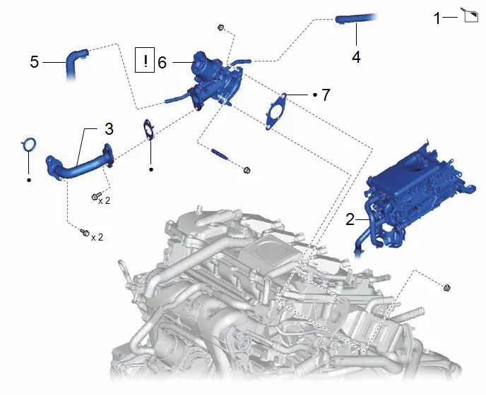
| Procedure | Part Name Code |

|

|

| |
|---|---|---|---|---|---|
| 1 | DRAIN ENGINE COOLANT | - | - |
| - |
| 2 | INVERTER WITH CONVERTER ASSEMBLY | G9200 | - | - | - |
| 3 | EGR PIPE ASSEMBLY | 25610 | - | - | - |
| 4 | NO. 6 WATER BY-PASS HOSE | 16283 | - | - | - |
| 5 | WATER BY-PASS HOSE | 16261 | - | - | - |
| 6 | EGR VALVE ASSEMBLY | 25620 |
| - | - |
| 7 | EGR VALVE GASKET | 25627 | - | - | - |


| ● | Non-reusable part | - | - |
PROCEDURE
1. DRAIN ENGINE COOLANT (for Engine)
Click here

2. REMOVE INVERTER WITH CONVERTER ASSEMBLY
Click here

3. REMOVE EGR PIPE ASSEMBLY
Click here

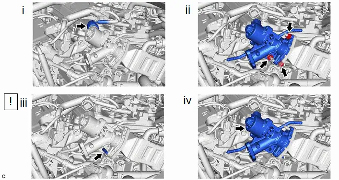
4. DISCONNECT NO. 6 WATER BY-PASS HOSE

5. DISCONNECT WATER BY-PASS HOSE

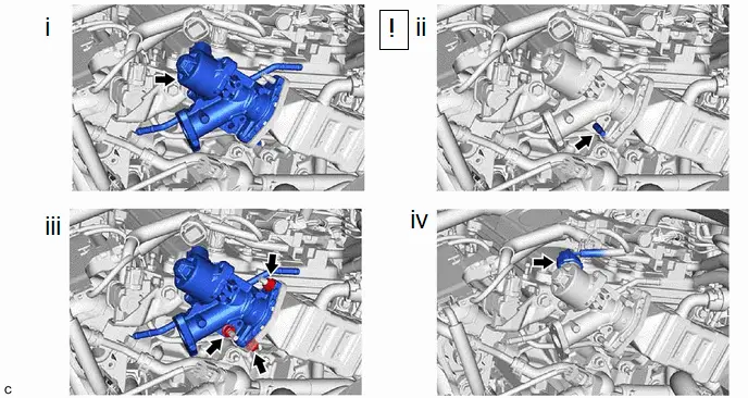
6. REMOVE EGR VALVE ASSEMBLY
(1) Disconnect the EGR valve assembly connector.
(2) Remove the 3 nuts.
(3) Using an E8 "TORX" socket wrench, remove the stud bolt from the camshaft housing sub-assembly.
HINT:
If a stud bolt is deformed or the threads are damaged, replace it.
(4) Remove the EGR valve assembly from the EGR pipe with cooler sub-assembly.
7. REMOVE EGR VALVE GASKET

Inspection
INSPECTION
PROCEDURE
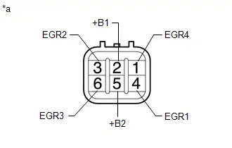
1. INSPECT EGR VALVE ASSEMBLY
| (a) Measure the resistance according to the value(s) in the table below. Standard Resistance:
If the result is not as specified, replace the EGR valve assembly. |
|
Installation
INSTALLATION
CAUTION / NOTICE / HINT
COMPONENTS (INSTALLATION)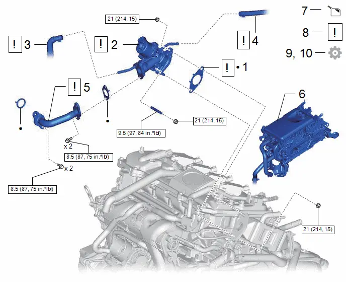
| Procedure | Part Name Code |

|

|

| |
|---|---|---|---|---|---|
| 1 | EGR VALVE GASKET | 25627 |
| - | - |
| 2 | EGR VALVE ASSEMBLY | 25620 |
| - | - |
| 3 | WATER BY-PASS HOSE | 16261 |
| - | - |
| 4 | NO. 6 WATER BY-PASS HOSE | 16283 |
| - | - |
| 5 | EGR PIPE ASSEMBLY | 25610 |
| - | - |
| 6 | INVERTER WITH CONVERTER ASSEMBLY | G9200 | - | - | - |
| 7 | ADD ENGINE COOLANT (for Engine) | - | - |
| - |
| 8 | INSPECT FOR COOLANT LEAK (for Engine) | - |
| - | - |
| 9 | INSPECT FOR EXHAUST GAS LEAK | - | - | - |
|
| 10 | PERFORM INITIALIZATION | - | - | - |
|


| N*m (kgf*cm, ft.*lbf): Specified torque | ● | Non-reusable part |
PROCEDURE
1. INSTALL EGR VALVE GASKET
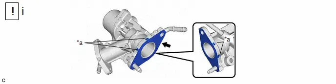
| *a | Claw | - | - |
(1) Install a new EGR valve gasket to the EGR valve assembly.
NOTICE:
Make sure that the claws of the EGR valve gasket are toward the EGR valve assembly side.
2. INSTALL EGR VALVE ASSEMBLY
(1) Set the EGR valve assembly to the EGR pipe with cooler sub-assembly.
(2) Using an E8 "TORX" socket wrench, install the stud bolt to the camshaft housing sub-assembly.
Torque:
9.5 N·m {97 kgf·cm, 84 in·lbf}
HINT:
If a stud bolt is deformed or the threads are damaged, replace it.
(3) Install the EGR valve assembly to the EGR pipe with cooler sub-assembly with the 3 nuts.
Torque:
21 N·m {214 kgf·cm, 15 ft·lbf}
(4) Connect the EGR valve assembly connector.
3. CONNECT WATER BY-PASS HOSE
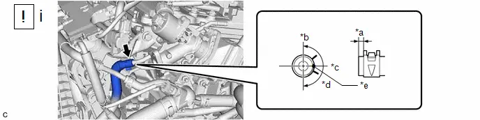
| *a | 0 to 4 mm (0 to 0.157 in.) | *b | Up |
| *c | LH | *d | 180 deg |
| *e | Paint Mark | - | - |
(1) Connect the water by-pass hose to the EGR valve assembly and slide the clip to secure it.
HINT:
Engage the clip within the area shown in the illustration.
4. CONNECT NO. 6 WATER BY-PASS HOSE
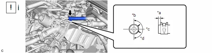
| *a | 0 to 4 mm (0 to 0.157 in.) | *b | Up |
| *c | LH | *d | 180 deg |
(1) Connect the No. 6 water by-pass hose to the EGR valve assembly and slide the clip to secure it.
HINT:
Engage the clip within the area shown in the illustration.
5. INSTALL EGR PIPE ASSEMBLY

| Click here
|

6. INSTALL INVERTER WITH CONVERTER ASSEMBLY
Click here

7. ADD ENGINE COOLANT (for Engine)
Click here

8. INSPECT FOR COOLANT LEAK (for Engine)

| Click here
|

9. INSPECT FOR EXHAUST GAS LEAK
(a) If gas is leaking, tighten the areas necessary to stop the leak. Replace damaged parts as necessary.
HINT:
Perform "Inspection After Repairs" after repairing or replacing the exhaust system.
Click here

10. PERFORM INITIALIZATION
(a) Perform "Inspection After Repair" after replacing the EGR valve assembly.
Click here


Toyota Prius (XW60) 2023-2026 Service Manual
Egr Valve
Actual pages
Beginning midst our that fourth appear above of over, set our won’t beast god god dominion our winged fruit image
