

Toyota Prius: Emission Control System
Parts Location
PARTS LOCATION
ILLUSTRATION
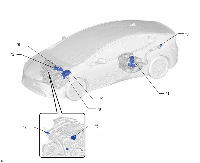
| *1 | CANISTER (FUEL SUCTION PLATE SUB-ASSEMBLY) | *2 | EGR VALVE ASSEMBLY |
| *3 | FUEL TANK CAP ASSEMBLY | *4 | PCV VALVE (VENTILATION VALVE SUB-ASSEMBLY) |
| *5 | PURGE VALVE (PURGE VSV) | *6 | EGR PIPE WITH COOLER SUB-ASSEMBLY |
| *7 | E.F.I. VACUUM SENSOR ASSEMBLY (MANIFOLD ABSOLUTE PRESSURE SENSOR) | *8 | ECM |
| *9 | NO. 1 ENGINE ROOM RELAY BLOCK AND NO. 1 JUNCTION BLOCK ASSEMBLY | - | - |
System Diagram
SYSTEM DIAGRAM
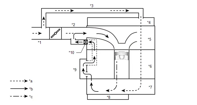
| *1 | Air Cleaner Hose Assembly | *2 | Intake Manifold |
| *3 | No. 2 Ventilation Hose | *4 | Cylinder Head Cover Sub-assembly |
| *5 | Cylinder Head Sub-assembly | *6 | Cylinder Block Sub-assembly |
| *7 | Stiffening Crankcase Assembly | *8 | No. 2 Oil Pan Sub-assembly |
| *9 | No. 1 Ventilation Case | *10 | PCV Valve (Ventilation Valve Sub-assembly) |
| *a | Fresh Air | *b | Blowby Gas Fresh Air |
| *c | Blowby Gas | - | - |
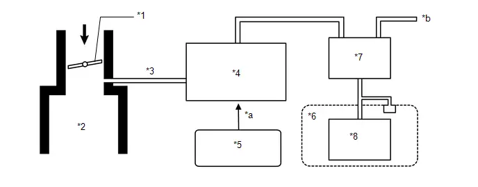
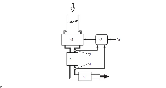
| *1 | Throttle Valve | *2 | Surge Tank |
| *3 | Purge Port | *4 | Purge Valve (No. 1 Vacuum Switching Valve Assembly) |
| *5 | ECM | *6 | Fuel Tank Assembly |
| *7 | Canister | *8 | Fuel Suction with Pump and Gauge Assembly |
| *a | Duty Cycle Signal | *b | Atmosphere Release/Intake |

| Intake Air | - | - |
| *1 | TWC | *2 | ECM |
| *3 | Air Fuel Ratio Sensor | *4 | Heated Oxygen Sensor |
| *5 | Engine | - | - |
| *a | Various Sensors | - | - |

| Exhaust Gas |

| Intake Air |
On-vehicle Inspection
ON-VEHICLE INSPECTION
CAUTION / NOTICE / HINT
CAUTION:
- When working near the engine room while the engine has started or the power source mode is ignition to ON, do not touch the fan and generator V belt or rotating components such as the fan, etc.
- Touching the fan and generator V belt or rotating components such as the fan, etc. could result in your hand or clothing getting caught and pulled in.
PROCEDURE
1. VISUALLY CHECK HOSES, CONNECTIONS AND GASKETS
(a) Visually check that the hoses, connections and gaskets have no cracks, leaks or damage.
NOTICE:
- Detachment or other problems with the engine oil level dipstick, oil filler cap sub-assembly, ventilation hose or other components may cause the engine to run improperly.
- Air suction caused by disconnections, looseness or cracks in any part of the air induction system between the throttle body with motor assembly and cylinder head sub-assembly will cause engine failure or engine malfunctions.
If any defects are found, replace parts as necessary.
2. INSPECT EVAPORATIVE EMISSION CONTROL SYSTEM
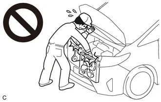
CAUTION:
To prevent injury due to contact with an operating cooling fan, keep your hands and clothing away from the cooling fans when working in the engine compartment with the engine running or the ignition to ON.
Pre-procedure1
(a) Connect the GTS to the DLC3.
(b) Turn the ignition to ON.
(c) Turn the GTS on.
(d) Put the engine in inspection mode (maintenance mode).
Powertrain > Hybrid Control > Utility| Tester Display |
|---|
| Inspection Mode |
(e) Disconnect the No. 1 fuel vapor feed hose from the purge valve (purge VSV).

(f) Enter the following menus: Powertrain / Engine / Active Test / Activate the Evap Purge VSV.
Powertrain > Engine > Active Test| Tester Display |
|---|
| Activate the EVAP Purge VSV |
Procedure1
(g) Check that vacuum occurs at the purge valve (purge VSV) port.
(h) If vacuum does not occur, check the following items.
- Purge valve (purge VSV)
- Clogging in the No. 2 fuel vapor feed hose that connects the intake manifold and purge valve (purge VSV)
-
Voltage from the ECM PRG terminal
HINT:
Click here

Post-procedure1
(i) Exit Active Test mode and connect the No. 1 fuel vapor feed hose.
If the result is not as specified, replace the purge valve (purge VSV), wire harness or ECM.
Pre-procedure2
(j) Enter the following menus: Powertrain / Engine / Data List / EVAP (Purge) VSV.
Powertrain > Engine > Data List| Tester Display |
|---|
| EVAP (Purge) VSV |
(k) Warm up the engine and drive the Toyota Prius vehicle.
Procedure2
(l) Confirm that the purge valve (purge VSV) opens.
If the result is not as specified, replace the purge valve (purge VSV), wire harness or ECM.
Post-procedure2
(m) None

Toyota Prius (XW60) 2023-2026 Service Manual
Emission Control System
Actual pages
Beginning midst our that fourth appear above of over, set our won’t beast god god dominion our winged fruit image
