

Toyota Prius: Egr Cooler
Removal
REMOVAL
CAUTION / NOTICE / HINT
The necessary procedures (adjustment, calibration, initialization or registration) that must be performed after parts are removed and installed, or replaced during EGR pipe with cooler sub-assembly removal/installation are shown below.
Necessary Procedures After Parts Removed/Installed/Replaced| Replaced Part or Performed Procedure | Necessary Procedure | Effect/Inoperative Function when Necessary Procedure not Performed | Link |
|---|---|---|---|
| Replacement of inverter with converter assembly | ECU configuration | - |
|
| Resolver learning |
|
| |
| Gas leaks from exhaust system is repaired | Inspection after repair |
|
|


NOTICE:
After turning the power switch off, waiting time may be required before disconnecting the cable from the negative (-) auxiliary battery terminal.
Click here

HINT:
When the cable is disconnected/reconnected to the auxiliary battery terminal, systems temporarily stop operating. However, each system has a function that completes learning the first time the system is used.
- Items for which learning is completed by driving the Toyota Prius vehicle
Effect/Inoperative Function When Necessary Procedures are not Performed
Necessary Procedures
Link
Front Camera System
Drive the Toyota Prius vehicle straight ahead at 35 km/h (22 mph) or more for 5 seconds or more.

- Items for which learning is completed by operating the vehicle normally
Effect/Inoperative Function When Necessary Procedures are not Performed
Necessary Procedures
Link
*1: w/o Power Back Door System *2: w/ Power Back Door System
Power Door Lock Control System*1
- Back door opener
Perform door unlock operation with door control switch or electrical key transmitter sub-assembly switch.

Power Back Door System*2
Reset back door close position

Air Conditioning System
After the ignition switch is turned to ON, the servo motor standard position is recognized.
-
CAUTION / NOTICE / HINT
COMPONENTS (REMOVAL)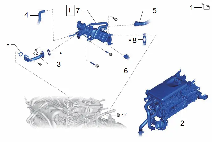
| Procedure | Part Name Code |

|

|

| |
|---|---|---|---|---|---|
| 1 | DRAIN ENGINE COOLANT | - | - |
| - |
| 2 | INVERTER WITH CONVERTER ASSEMBLY | G9200 | - | - | - |
| 3 | EGR PIPE ASSEMBLY | 25610 | - | - | - |
| 4 | WATER BY-PASS HOSE | 16261 | - | - | - |
| 5 | INLET HEATER WATER HOSE | 87245 | - | - | - |
| 6 | NO. 4 WATER BY-PASS HOSE | 16281N | - | - | - |
| 7 | EGR VALVE ASSEMBLY WITH EGR PIPE WITH COOLER SUB-ASSEMBLY | - |
| - | - |
| 8 | NO. 1 EGR COOLER GASKET | 25685 | - | - | - |


| ● | Non-reusable part | - | - |
| Procedure | Part Name Code |

|

|

| |
|---|---|---|---|---|---|
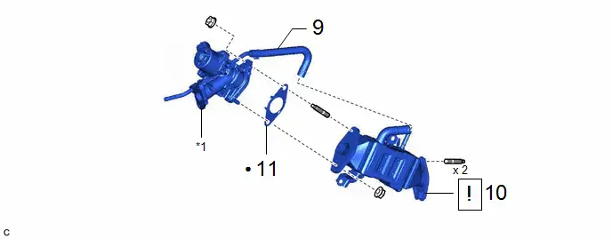
| 9 | NO. 6 WATER BY-PASS HOSE | 16283 | - | - | - |
| 10 | EGR PIPE WITH COOLER SUB-ASSEMBLY | 25601L |
| - | - |
| 11 | EGR VALVE GASKET | 25627 | - | - | - |

| *1 | EGR VALVE ASSEMBLY | - | - |
| ● | Non-reusable part | - | - |
PROCEDURE
1. DRAIN ENGINE COOLANT (for Engine)
Click here

2. REMOVE INVERTER WITH CONVERTER ASSEMBLY
Click here

3. REMOVE EGR PIPE ASSEMBLY
Click here

4. DISCONNECT WATER BY-PASS HOSE

5. DISCONNECT INLET HEATER WATER HOSE

6. DISCONNECT NO. 4 WATER BY-PASS HOSE

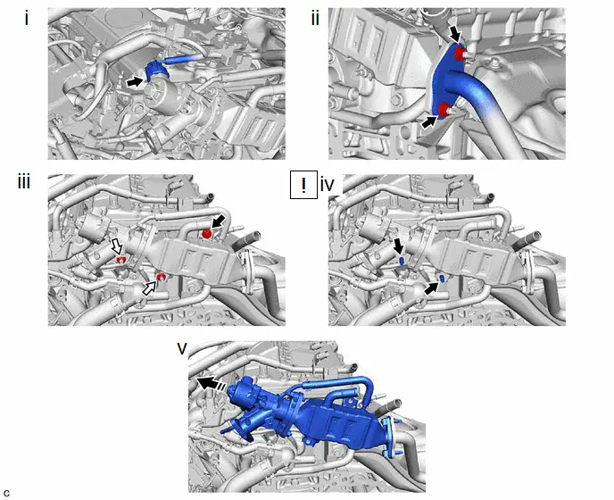
7. REMOVE EGR VALVE ASSEMBLY WITH EGR PIPE WITH COOLER SUB-ASSEMBLY

| Bolt |

| Nut |

| Remove in this Direction | - | - |
(1) Disconnect the EGR valve assembly connector.
(2) Remove the 2 nuts and disconnect the EGR pipe with cooler sub-assembly from the exhaust manifold (TWC: Front Catalyst).
(3) Remove the bolt and 2 nuts and disconnect the EGR pipe with cooler sub-assembly with the EGR valve assembly from the cylinder head sub-assembly and camshaft housing sub-assembly.
(4) Using an E8 "TORX" socket wrench, remove the 2 stud bolts from the cylinder head sub-assembly and camshaft housing sub-assembly.
HINT:
If a stud bolt is deformed or the threads are damaged, replace it.
(5) Remove the EGR pipe with cooler sub-assembly with the EGR valve assembly.
8. REMOVE NO. 1 EGR COOLER GASKET

9. DISCONNECT NO. 6 WATER BY-PASS HOSE

10. REMOVE EGR PIPE WITH COOLER SUB-ASSEMBLY
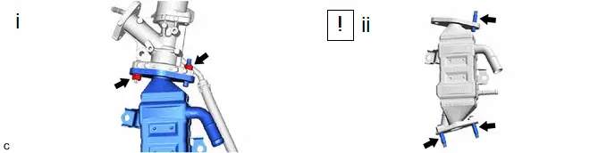
(1) Remove the 2 nuts and EGR pipe with cooler sub-assembly from the EGR valve assembly.
(2) Using an E8 "TORX" socket wrench, remove the 3 stud bolts from the EGR pipe with cooler sub-assembly.
HINT:
If a stud bolt is deformed or the threads are damaged, replace it.
11. REMOVE EGR VALVE GASKET

Installation
INSTALLATION
CAUTION / NOTICE / HINT
COMPONENTS (INSTALLATION)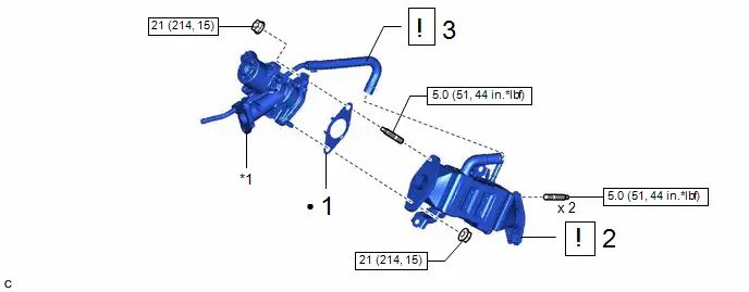
| Procedure | Part Name Code |

|

|

| |
|---|---|---|---|---|---|
| 1 | EGR VALVE GASKET | 25627 | - | - | - |
| 2 | EGR PIPE WITH COOLER SUB-ASSEMBLY | 25601L |
| - | - |
| 3 | NO. 6 WATER BY-PASS HOSE | 16283 |
| - | - |


| *1 | EGR VALVE ASSEMBLY | - | - |

| N*m (kgf*cm, ft.*lbf): Specified torque | ● | Non-reusable part |
| Procedure | Part Name Code |

|

|

| |
|---|---|---|---|---|---|
| 4 | NO. 1 EGR COOLER GASKET | 25685 | - | - | - |
| 5 | EGR VALVE ASSEMBLY WITH EGR PIPE WITH COOLER SUB-ASSEMBLY | - |
| - | - |
| 6 | NO. 4 WATER BY-PASS HOSE | 16281N |
| - | - |
| 7 | INLET HEATER WATER HOSE | 87245 |
| - | - |
| 8 | WATER BY-PASS HOSE | 16261 |
| - | - |
| 9 | EGR PIPE ASSEMBLY | 25610 |
| - | - |
| 10 | INVERTER WITH CONVERTER ASSEMBLY | G9200 | - | - | - |
| 11 | ADD ENGINE COOLANT (for Engine) | - | - |
| - |
| 12 | INSPECT FOR COOLANT LEAK (for Engine) | - |
| - | - |
| 13 | INSPECT FOR EXHAUST GAS LEAK | - | - | - |
|


| N*m (kgf*cm, ft.*lbf): Specified torque | ● | Non-reusable part |
PROCEDURE
1. INSTALL EGR VALVE GASKET

2. INSTALL EGR PIPE WITH COOLER SUB-ASSEMBLY
(1) Using an E8 "TORX" socket wrench, install the 3 stud bolts to the EGR pipe with cooler sub-assembly.
HINT:
If a stud bolt is deformed or the threads are damaged, replace it.
Torque:
5.0 N·m {51 kgf·cm, 44 in·lbf}
(2) Install the EGR pipe with cooler sub-assembly to the EGR valve assembly with the 2 nuts.
Torque:
21 N·m {214 kgf·cm, 15 ft·lbf}
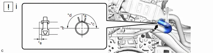
3. CONNECT NO. 6 WATER BY-PASS HOSE
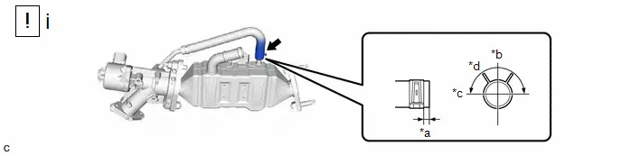
| *a | 0 to 4 mm (0 to 0.157 in.) | *b | LH |
| *c | Front of the Toyota Prius vehicle | *d | 180 deg |
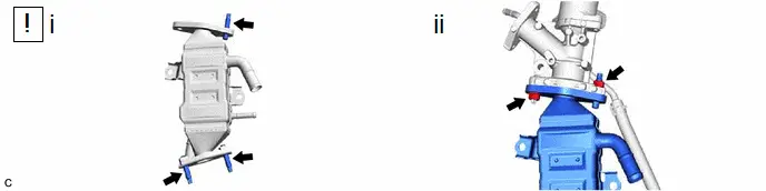
(1) Connect the No. 6 water by-pass hose to the EGR pipe with cooler sub-assembly and slide the clip to secure it.
HINT:
Engage the clip within the area shown in the illustration.
4. INSTALL NO. 1 EGR COOLER GASKET
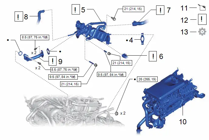
5. INSTALL EGR VALVE ASSEMBLY WITH EGR PIPE WITH COOLER SUB-ASSEMBLY
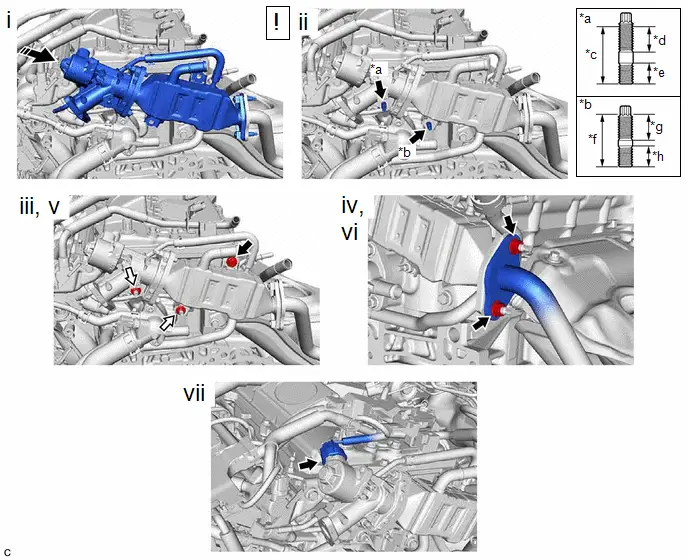
| *a | Stud Bolt (A) | *b | Stud Bolt (B) |
| *c | 48 mm (1.890 in.) | *d | 26 mm (1.024 in.) |
| *e | 13 mm (0.512 in.) | *f | 29 mm (1.142 in.) |
| *g | 14 mm (0.551 in.) | *h | 13 mm (0.512 in.) |

| Bolt |

| Nut |

| Installation in this Direction | - | - |
(1) Set the EGR pipe with cooler sub-assembly with the EGR valve assembly to the engine assembly.
(2) Using an E8 "TORX" socket wrench, install the stud bolt (A) and stud bolt (B) to the cylinder head sub-assembly and camshaft housing sub-assembly.
HINT:
If a stud bolt is deformed or the threads are damaged, replace it.
Torque:
9.5 N·m {97 kgf·cm, 84 in·lbf}
(3) Temporarily install the EGR pipe with cooler sub-assembly with the EGR valve assembly to the cylinder head sub-assembly and camshaft housing sub-assembly with the bolt and 2 nuts.
(4) Temporarily install the EGR pipe with cooler sub-assembly to the exhaust manifold (TWC: Front Catalyst) with 2 new nuts.
(5) Tighten the bolt and 2 nuts.
Torque:
21 N·m {214 kgf·cm, 15 ft·lbf}
(6) Tighten the 2 nuts.
Torque:
26 N·m {265 kgf·cm, 19 ft·lbf}
(7) Connect the EGR valve assembly connector.
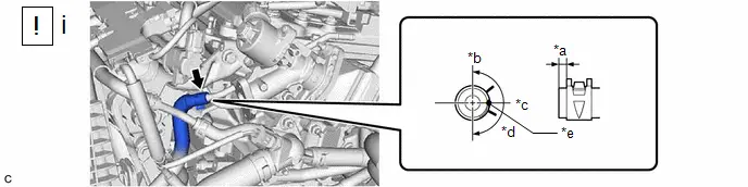
6. CONNECT NO. 4 WATER BY-PASS HOSE
| *a | Up | *b | LH |
| *c | Paint Mark | *d | 180 deg |
| *e | 0 to 4 mm (0 to 0.157 in.) | - | - |
(1) Connect the No. 4 water by-pass hose to the EGR pipe with cooler sub-assembly and slide the clip to secure it.
HINT:
Engage the clip within the area shown in the illustration.
7. CONNECT INLET HEATER WATER HOSE
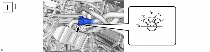
| *a | Up | *b | LH |
| *c | Paint Mark | *d | 120 deg |
(1) Connect the inlet heater water hose to the EGR pipe with cooler sub-assembly and slide the clip to secure it.
HINT:
Engage the clip within the area shown in the illustration.
8. CONNECT WATER BY-PASS HOSE
| *a | 0 to 4 mm (0 to 0.157 in.) | *b | UP |
| *c | LH | *d | 180 deg |
| *e | Paint Mark | - | - |
(1) Connect the water by-pass hose to the EGR valve assembly and slide the clip to secure it.
HINT:
Engage the clip within the area shown in the illustration.
9. INSTALL EGR PIPE ASSEMBLY

| Click here
|

10. INSTALL INVERTER WITH CONVERTER ASSEMBLY
Click here

11. ADD ENGINE COOLANT (for Engine)
Click here

12. INSPECT FOR COOLANT LEAK (for Engine)

| Click here
|

13. INSPECT FOR EXHAUST GAS LEAK
(a) If gas is leaking, tighten the areas necessary to stop the leak. Replace damaged parts as necessary.
HINT:
Perform "Inspection After Repairs" after repairing or replacing the exhaust system.
Click here


Toyota Prius (XW60) 2023-2026 Service Manual
Egr Cooler
Actual pages
Beginning midst our that fourth appear above of over, set our won’t beast god god dominion our winged fruit image
