

Toyota Prius: Canister
On-vehicle Inspection
ON-VEHICLE INSPECTION
PROCEDURE
1. INSPECT CANISTER (FUEL SUCTION PLATE SUB-ASSEMBLY) (for Fuel Tank Cap Method) (INSPECT THE EVAPORATIVE EMISSION CONTROL SYSTEM)
HINT:
Click here

2. INSPECT CANISTER (FUEL SUCTION PLATE SUB-ASSEMBLY) (for Fuel Tank Cap Method) (CHECK FOR CLOGS IN THE AIR FILTER (When Not Using The GTS))
Pre-procedure1
(a) Start the engine.
(b) Warm up the engine.
(c) Allow the engine to idle for 15 minutes.
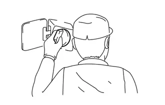
(d) Open the fuel tank cap assembly to discharge the pressure in the fuel tank assembly.
(e) Close the fuel tank cap assembly and allow the engine to idle for 30 seconds.
Procedure1
| (f) Open the fuel tank cap assembly again and check for inhalation sounds. OK: No whooshing sounds (inhalation sound) are heard. HINT: If there is a smell of gasoline and a whooshing sound (exhalation sound) is heard, positive pressure in the fuel tank assembly is being discharged. This is not a malfunction. |
|
Post-procedure1
(g) None
3. INSPECT CANISTER (FUEL SUCTION PLATE SUB-ASSEMBLY) (for Fuel Tank Cap Method) (CHECK FOR CLOGS IN THE AIR FILTER (When Using The GTS))
Pre-procedure2
(a) Connect the GTS to the DLC3.
(b) Start the engine.
(c) Turn the GTS on.
(d) Enter the following menus: Powertrain / Engine / Active Test / Activate the EVAP Purge VSV.
Powertrain > Engine > Active Test| Tester Display |
|---|
| Activate the EVAP Purge VSV |
(e) Open the fuel tank cap assembly to discharge the pressure in the fuel tank assembly.
(f) Perform the Active Test "Activate the EVAP Purge VSV" while the engine is idling.
(g) Close the fuel tank cap assembly and allow the engine to idle for 30 seconds.
Procedure2
(h) Open the fuel tank cap assembly and check for inhalation sounds.
OK:
No whooshing sounds (inhalation sound) are heard.
HINT:
If there is a smell of gasoline and a whooshing sound (exhalation sound) is heard, positive pressure in the fuel tank assembly is being discharged. This is not a malfunction.
Post-procedure2
(i) None
4. INSPECT CANISTER (FUEL SUCTION PLATE SUB-ASSEMBLY) (for Vacuum Measurement Method) (VISUALLY CHECK THE CANISTER (FUEL SUCTION PLATE SUB-ASSEMBLY) FOR AIRTIGHTNESS)
(a) Visually check the canister (fuel suction plate sub-assembly) for cracks or damage, and check that there is no gasoline smell.
5. INSPECT CANISTER (FUEL SUCTION PLATE SUB-ASSEMBLY) (for Vacuum Measurement Method) (INSPECT THE AIRFLOW OF THE CANISTER (FUEL SUCTION PLATE SUB-ASSEMBLY))
NOTICE:
When inspecting with parts installed on the Toyota Prius vehicle, be sure to remove the fuel tank cap assembly.
| (a) Apply compressed air to the port (A) and check that the air flows out from the port (B). OK: Air flows out from the port (B). |
|
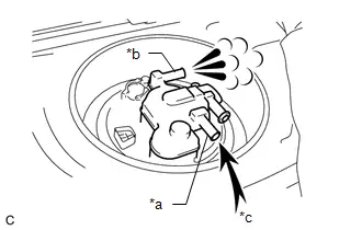
| (b) Close the port (A) and apply compressed air to the port (B). OK: Air does not flow at first. By gradually increasing the pressure, air flows when the pressure in the port reaches a certain level. |
|
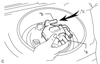
| (c) Using a vacuum pump, apply vacuum to the port (B) with the port (A) closed. OK: The vacuum is maintained at first. By gradually increasing the vacuum, air flows and the vacuum decreases after the vacuum reaches a certain level. |
|
6. INSPECT CANISTER (FUEL SUCTION PLATE SUB-ASSEMBLY) (for Vacuum Measurement Method) (CHECK FOR CLOGS IN THE AIR FILTER (When Not Using The GTS))
Pre-procedure1
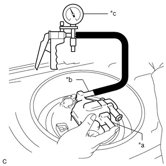
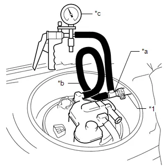
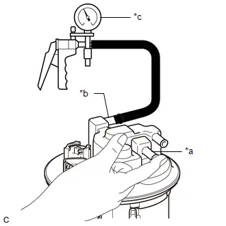
| (a) Connect the fuel hose to the canister (fuel suction plate sub-assembly) via the 3-way connector, hose and vacuum pump as shown in the illustration. |
|

(b) Start the engine.
(c) Warm up the engine.
(d) Allow the engine to idle for 15 minutes.
Procedure1
(e) Check the indicator needle of the vacuum pump.
OK:
The indicator needle of the vacuum pump does not rise from its initial position.
HINT:
The indicator needle may shake due to engine vibration, etc., but if it immediately returns to its initial position, there is no problem.
Post-procedure1
(f) None
7. INSPECT CANISTER (FUEL SUCTION PLATE SUB-ASSEMBLY) (for Vacuum Measurement Method) (CHECK FOR CLOGS IN THE AIR FILTER (When Using The GTS))
Pre-procedure1
| (a) Connect the fuel hose to the canister (fuel suction plate sub-assembly) via the 3-way connector, hose and vacuum pump as shown in the illustration. |
|
(b) Connect the GTS to the DLC3.
(c) Start the engine.
(d) Turn the GTS on.
(e) Enter the following menus: Powertrain / Engine / Active Test / Activate the EVAP Purge VSV.
Powertrain > Engine > Active Test| Tester Display |
|---|
| Activate the EVAP Purge VSV |
(f) Perform the Active Test "Activate the EVAP Purge VSV" while the engine is idling.
Procedure1
(g) Check the needle of the vacuum pump.
OK:
The needle of the vacuum pump does not rise from its initial position.
HINT:
The indicator needle may shake due to engine vibration, etc., but if it immediately returns to its initial position, there is no problem.
Post-procedure1
(h) None
Removal
REMOVAL
CAUTION / NOTICE / HINT
The necessary procedures (adjustment, calibration, initialization or registration) that must be performed after parts are removed and installed, or replaced during canister (fuel suction plate sub-assembly) removal/installation are shown below.
Necessary Procedures After Parts Removed/Installed/Replaced| Replaced Part or Performed Procedure | Necessary Procedure | Effect/Inoperative Function when Necessary Procedure not Performed | Link |
|---|---|---|---|
| Replacement of fuel pump | Inspection after repair |
|
|

NOTICE:
After turning the power switch off, waiting time may be required before disconnecting the cable from the negative (-) auxiliary battery terminal.
Click here

HINT:
When the cable is disconnected/reconnected to the auxiliary battery terminal, systems temporarily stop operating. However, each system has a function that completes learning the first time the system is used.
- Items for which learning is completed by driving the Toyota Prius vehicle
Effect/Inoperative Function When Necessary Procedures are not Performed
Necessary Procedures
Link
Front Camera System
Drive the Toyota Prius vehicle straight ahead at 35 km/h (22 mph) or more for 5 seconds or more.

- Items for which learning is completed by operating the vehicle normally
Effect/Inoperative Function When Necessary Procedures are not Performed
Necessary Procedures
Link
*1: w/o Power Back Door System *2: w/ Power Back Door System
Power Door Lock Control System*1
- Back door opener
Perform door unlock operation with door control switch or electrical key transmitter sub-assembly switch.

Power Back Door System*2
Reset back door close position

Air Conditioning System
After the ignition switch is turned to ON, the servo motor standard position is recognized.
-
CAUTION / NOTICE / HINT
COMPONENTS (REMOVAL)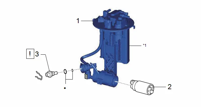
| Procedure | Part Name Code |

|

|

| |
|---|---|---|---|---|---|
| 1 | FUEL SUCTION TUBE WITH PUMP AND GAUGE ASSEMBLY | 77020A | - | - | - |
| 2 | FUEL PUMP | 23221 | - | - | - |
| 3 | FUEL PRESSURE REGULATOR ASSEMBLY | 23280J |
| - | - |

| *1 | CANISTER (FUEL SUCTION PLATE SUB-ASSEMBLY) | - | - |
| ● | Non-reusable part | - | - |
PROCEDURE
1. REMOVE FUEL SUCTION TUBE WITH PUMP AND GAUGE ASSEMBLY
Click here

2. REMOVE FUEL PUMP
Click here

3. REMOVE FUEL PRESSURE REGULATOR ASSEMBLY

| Click here
|

Inspection
INSPECTION
PROCEDURE
1. CHECK CANISTER (FUEL SUCTION PLATE SUB-ASSEMBLY) (VISUALLY CHECK THE CANISTER (FUEL SUCTION PLATE SUB-ASSEMBLY))
(a) Visually check the canister (fuel suction plate sub-assembly) for cracks or damage.
If cracks or damage are found, replace the canister (fuel suction plate sub-assembly).
2. CHECK CANISTER (FUEL SUCTION PLATE SUB-ASSEMBLY) (INSPECT THE VENTILATION OF THE CANISTER (FUEL SUCTION PLATE SUB-ASSEMBLY))
| (a) Apply compressed air to the port (A) and check that the air flows out from the port (B). OK: The air flows from the port (B). |
|
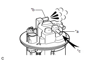
| (b) Close the port (A), apply compressed air to the port (B). OK: Air does not flow at first. By gradually increasing the pressure, air flows when the pressure in the port reaches a certain level. |
|
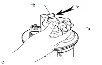
| (c) Using a vacuum pump, apply vacuum to the port (B) with the port (A) closed. OK: The vacuum is maintained at first. By gradually increasing the vacuum, air flows and the vacuum decreases after the vacuum reaches a certain level. |
|
Installation
INSTALLATION
CAUTION / NOTICE / HINT
COMPONENTS (INSTALLATION)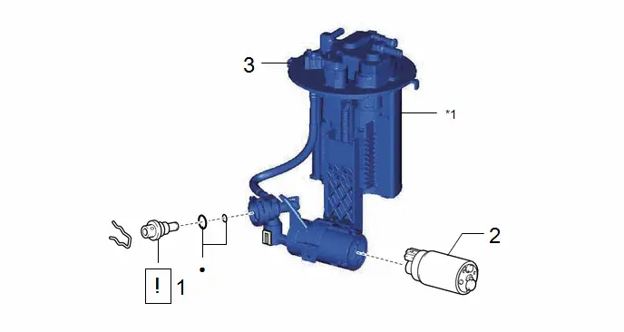
| Procedure | Part Name Code |

|

|

| |
|---|---|---|---|---|---|
| 1 | FUEL PRESSURE REGULATOR ASSEMBLY | 23280J |
| - | - |
| 2 | FUEL PUMP | 23221 | - | - | - |
| 3 | FUEL SUCTION TUBE WITH PUMP AND GAUGE ASSEMBLY | 77020A | - | - | - |

| *1 | CANISTER (FUEL SUCTION PLATE SUB-ASSEMBLY) | - | - |
| ● | Non-reusable part | - | - |
PROCEDURE
1. INSTALL FUEL PRESSURE REGULATOR ASSEMBLY

| Click here
|

2. INSTALL FUEL PUMP
Click here

3. INSTALL FUEL SUCTION TUBE WITH PUMP AND GAUGE ASSEMBLY
Click here


Toyota Prius (XW60) 2023-2026 Service Manual
Canister
Actual pages
Beginning midst our that fourth appear above of over, set our won’t beast god god dominion our winged fruit image
