

Toyota Prius: Driver Monitor Camera System
- Precaution
- Parts Location
- System Diagram
- How To Proceed With Troubleshooting
- Utility
- Problem Symptoms Table
- Terminals Of Ecu
- Freeze Frame Data
- Data List / Active Test
- VEHICLE CONTROL HISTORY (RoB)
- Driver Monitor Camera Control System Internal Power Supply Failure (C1A3000,C1A3504,C1A3604)
- Driver Monitor Camera Control System Bus Signal / Message Failure (C1A3108,C1A3187)
- Driver Monitor Camera Component Internal Failure (C1A3196)
- LED Controller in Driver Monitor Camera Control System Actuator Stuck (C1A3471)
- Lost Communication with ECM/PCM "A" Missing Message (U010087,...,U029387)
- Software Incompatibility with Body Control Module Not Programmed (U032251,U032257)
Precaution
PRECAUTION
PRECAUTIONS FOR DISCONNECTING CABLE FROM NEGATIVE (-) AUXILIARY BATTERY TERMINAL
NOTICE:
- After the ignition switch is turned off, there may be a waiting time
before disconnecting the negative (-) auxiliary battery terminal.
Click here

HINT:
When disconnecting and reconnecting the auxiliary battery, there is an automatic learning function that completes learning when the respective system is used.
Click here

PRECAUTIONS FOR DRIVER MONITOR CAMERA SYSTEM
(a) In the following situations, it may not be possible to recognize the driver's face, or to detect the driver's facial direction, line-of-sight, whether their eyes are open or closed, etc.
(1) When sunlight is shining on the driver monitor camera in the cabin.
(2) When sunlight is shining on the driver's face.
(3) When the cabin light level changes between sunlight and shadow repeatedly.
(4) When the eyes, nose, mouth and contours of the face are hidden, and the characteristic points of the face cannot be recognized.
(5) When the driver is wearing eyeglasses.
(6) When the driver is wearing sunglasses that do not allow infrared light to pass through easily.
(7) When the driver is wearing a mask.
(8) When the driver is wearing circle contact lenses (to make the iris appear larger).
(9) When the driver's eyes are hidden by eyeglass frames, hair, etc., and the driver's eyes cannot be detected.
(10) When light reflected on the lenses of a pair of eyeglasses or sunglasses blocks the eyes.
(11) When the driver is wearing an eyepatch.
(12) When the driver is wearing a hat low over the eyes.
(13) When makeup prevents the characteristic points such as the eyes, mouth and contours of the face from being recognized.
(14) When there are 2 or more faces in and around the driver seat, such as when a passenger in the passenger seat or rear seat leans toward the driver seat.
(15) When the driver's hand on the steering wheel covers the face.
(16) When the driver's driving posture is abnormal, such as when leaning forward or sticking their face out the window.
(17) When the driver moves outside the viewing angle of the driver monitor camera, and the characteristic points of the face can no longer be detected.
(18) When the driver narrows their eyes when laughing or because of dazzling bright light.
(19) When the installation position becomes significantly slanted due to unexpected contact or impact to the driver monitor camera.
(20) When the temperature of the driver monitor camera is high.
(21) When the lens cover surface of the driver monitor camera is dirty or damaged.
(22) When there is an obstruction between the driver monitor camera and the driver's face.
(23) When the driver is wearing an eye mask or a mask with eyes drawn on it.
PRECAUTIONS WHEN REPLACING PARTS
(a) When replacing the driver monitor ECU assembly, make sure to replace it with a new one.
HANDLING AND SERVICE PRECAUTIONS
(a) After removing and installing any ECUs or sensors, make sure to check for DTCs and confirm that no DTCs are output.
(b) Observe all the following precautions when handling the driver monitor camera since it is a precision instrument.
(1) Do not subject the driver monitor camera to a strong impact or force.
(2) Do not disassemble the driver monitor camera.
(3) When replacing, etc. the driver monitor camera, never touch the surface of the driver monitor camera.
NOTICE:
If the surface of the driver monitor camera is touched, wipe it with a soft, dry cloth.
(4) Do not use detergent or organic solvent which could corrode resin on the driver monitor camera.
PRECAUTION FOR SURROUNDING PARTS OF DRIVER MONITOR CAMERA
(a) Do not attach stickers or install accessories to the front surface or other surfaces of the driver monitor camera.
HINT:
- If installation cannot be avoided, make sure it does not overlap on the front surface of the driver monitor camera.
- This may affect the visual field of the driver monitor camera and the driver monitor may not operate normally.
Parts Location
PARTS LOCATION
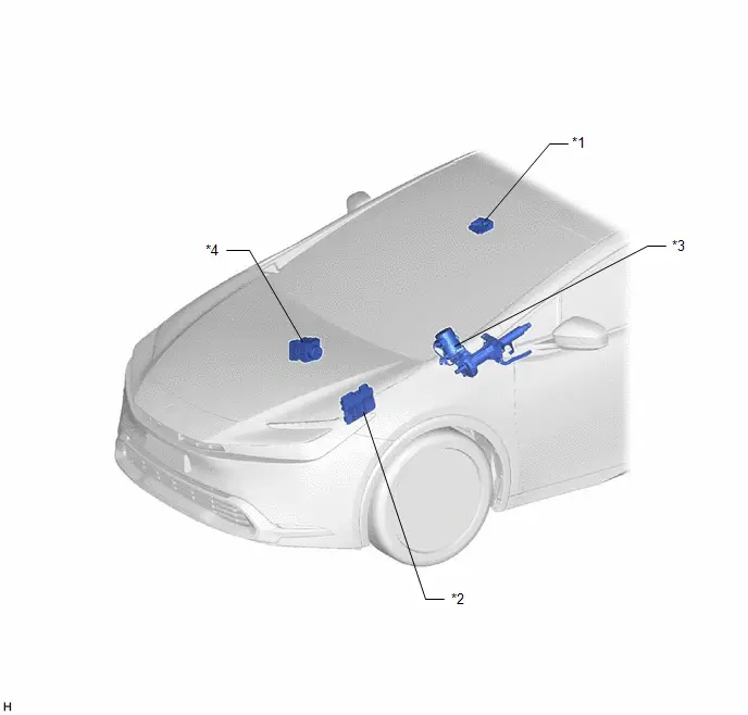
ILLUSTRATION
|
*1 |
FORWARD RECOGNITION CAMERA |
*2 |
ECM |
|
*3 |
POWER STEERING ECU ASSEMBLY |
*4 |
NO. 2 SKID CONTROL ECU (BRAKE ACTUATOR ASSEMBLY) |
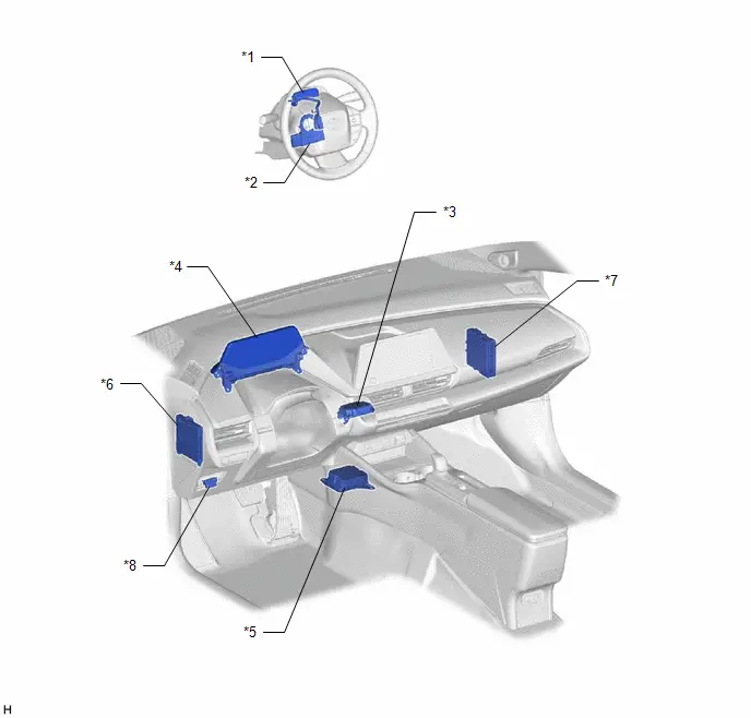
ILLUSTRATION
|
*1 |
DRIVER MONITOR CAMERA |
*2 |
STEERING SENSOR |
|
*3 |
DRIVER MONITOR ECU ASSEMBLY |
*4 |
COMBINATION METER ASSEMBLY |
|
*5 |
AIRBAG ECU ASSEMBLY |
*6 |
MAIN BODY ECU (MULTIPLEX NETWORK BODY ECU) |
|
*7 |
HYBRID Toyota Prius Vehicle CONTROL ECU |
*8 |
DLC3 |
System Diagram
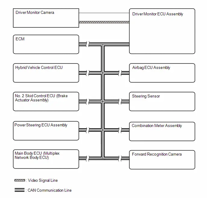
SYSTEM DIAGRAM
How To Proceed With Troubleshooting
CAUTION / NOTICE / HINT
HINT:
- Use the following procedure to troubleshoot the driver monitor camera system.
- *: Use the GTS.
PROCEDURE
|
1. |
Toyota Prius Vehicle BROUGHT TO WORKSHOP |
|

|
2. |
CUSTOMER PROBLEM ANALYSIS |
HINT:
- In troubleshooting, confirm that the problem symptoms have been accurately identified. Preconceptions should be discarded in order to make an accurate judgment. To clearly understand what the problem symptoms are, it is extremely important to ask the customer about the problem and the conditions at the time the malfunction occurred.
- Gather as much information as possible for reference. Past problems that seem unrelated may also help in some cases.
- The following 5 items are important points for problem analysis:
What
Toyota Prius Vehicle model, system name
When
Date, time, occurrence frequency
Where
Road conditions
Under what conditions?
Driving conditions, weather conditions
How did it happen?
Problem symptoms
|

|
3. |
PRE-CHECK |
(a) Measure the auxiliary battery voltage with the ignition switch off.
Standard voltage:
11 to 14 V
HINT:
If the voltage is below 11 V, recharge or replace the auxiliary battery before proceeding to the next step.
(b) Check the fuses and relays.
(c) Check the connector connections and terminals to make sure that there are no abnormalities such as loose connections, deformation, etc.
|

|
4. |
CHECK COMMUNICATION FUNCTION OF CAN COMMUNICATION SYSTEM* |
(a) Using the GTS, check for CAN communication system DTCs.
for HEV Model: Click here

for PHEV Model: Click here

|
Result |
Proceed to |
|---|---|
|
CAN DTCs are not output |
A |
|
CAN DTCs are output |
B |
| B |

|
GO TO CAN COMMUNICATION SYSTEM for HEV Model: Click here
for PHEV Model: Click here
|


|

|
5. |
CHECK DTC* |
(a) Check for DTCs and note any codes that are output.
Chassis > Driver Monitor Camera Control > Trouble Codes(b) Clear the DTCs.
Chassis > Driver Monitor Camera Control > Clear DTCs(c) Recheck for DTCs. Try to reproduce the DTCs by duplicating the conditions indicated by the DTCs.
Chassis > Driver Monitor Camera Control > Trouble Codes|
Result |
Proceed to |
|---|---|
|
DTCs are not output (Fault can be simulated) |
A |
|
DTCs are not output (Fault cannot be simulated) |
B |
|
DTCs are output. |
C |
| B |

|
USE SIMULATION METHOD TO CHECK |
| C |

|
GO TO DIAGNOSTIC TROUBLE CODE CHART |
|

|
6. |
CHECK FOR Toyota Prius Vehicle CONTROL HISTORY (RoB)* |
(a) Check for vehicle control history (RoB) and note any codes that are output.
Chassis > Driver Monitor Camera Control > Utility|
Tester Display |
|---|
|
Toyota Prius Vehicle Control History (RoB) |
(b) If the vehicle control history (RoB) is output, record it.
|
Result |
Proceed to |
|---|---|
|
Toyota Prius Vehicle control history (RoB) is not output |
A |
|
Vehicle control history (RoB) is output |
B |
| B |

|
GO TO Toyota Prius Vehicle CONTROL HISTORY (RoB) |
|

|
7. |
PROBLEM SYMPTOMS TABLE |
(a) Refer to Problem Symptoms Table.
Click here

|
Result |
Proceed to |
|---|---|
|
Fault is not listed in Problem Symptoms Table. |
A |
|
Fault is listed in Problem Symptoms Table. |
B |
| B |

|
ADJUST, REPAIR OR REPLACE IN ACCORDANCE WITH PROBLEM SYMPTOMS TABLE |
|

|
8. |
PERFORM TROUBLESHOOTING* |
(a) Data List / Active Test
Click here

(b) Refer to Terminals of ECU.
Click here

|

|
9. |
ADJUST, REPAIR OR REPLACE |
|

|
10. |
CONFIRMATION TEST |
| NEXT |

|
END |
Utility
UTILITY
HINT:
- It is possible to use the GTS to check whether or not DTC judgment has been completed.
- This procedure may be used to confirm whether DTCs are output after simulating malfunction symptoms or after finishing repairs.
ALL READINESS
(a) Using the GTS, clear the DTCs.
(Even if no DTC is output, perform the clear operation)
Chassis > Driver Monitor Camera Control > Clear DTCs(b) Turn the ignition switch off and wait for at least 2 minutes.
(c) Perform the DTC judgment driving pattern to run the DTC judgment.
(d) Perform "All Readiness" according to the display on the GTS.
Chassis > Driver Monitor Camera Control > Utility|
Tester Display |
|---|
|
All Readiness |
(e) Input the DTC to be confirmed.
(f) Check the DTC judgment result.
|
GTS Display |
Description |
|---|---|
|
Normal |
|
|
Abnormal |
|
|
Incomplete |
|
|
N/A |
|
If the judgment result shows Incomplete or N/A, perform the DTC confirmation driving pattern again.
(g) Turn the ignition switch off.
IMAGE INFORMATION CLEAR
HINT:
This deletes stored image data.
(a) Perform "Image Information Clear" according to the display on the GTS.
Chassis > Driver Monitor Camera Control > Utility|
Tester Display |
|---|
|
Image Information Clear |
IMAGE RECORD SETTING
HINT:
This changes the settings for storing image data.
(a) Perform "Image Record Setting" according to the display on the GTS.
Chassis > Driver Monitor Camera Control > Utility|
Tester Display |
|---|
|
Image Record Setting |
Problem Symptoms Table
PROBLEM SYMPTOMS TABLE
Driver Monitor Function|
Symptom |
Suspected Area |
Link |
|---|---|---|
|
The system cannot detect the driver's face correctly |
Using the Data List, check that "Face Detection Status" is "Detected". |
|
|
Using the Data List, check that the standard for the "Facial Direction" output value when the driver is facing forward is within the normal range. |
|
|
|
Driver monitor camera |
|
|
|
Driver monitor ECU assembly |
|
|
|
The system cannot detect the driver's line of sight correctly |
Using the Data List, check that "Sunglasses Detection Status" is "Not Detected" |
|
|
Using the Data List, check that the standard for the "Eye Direction Angle" output value when the driver is facing forward is within the normal range. |
|
|
|
Driver monitor camera |
|
|
|
Driver monitor ECU assembly |
|


Terminals Of Ecu
TERMINALS OF ECU
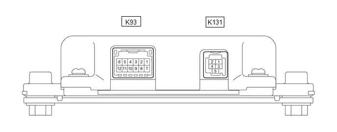
DRIVER MONITOR ECU ASSEMBLY
(a) Measure the voltage and resistance according to the value(s) in the table below.
|
Terminal No. (Symbol) |
Terminal Description |
Condition |
Specified Condition |
|---|---|---|---|
|
K93-3 (LS) - Body ground |
LED ground |
Always |
Below 1 Ω |
|
K93-4 (LP) - Body ground |
LED power source |
Ignition switch ON |
6 to 9 V |
|
K93-5 (CANH) - Body ground |
CAN communication signal |
Ignition switch off → Ignition switch ON |
Below 1 V → Pulse generation |
|
K93-6 (CANL) - Body ground |
CAN communication signal |
Ignition switch off → Ignition switch ON |
Below 1 V → Pulse generation |
|
K93-7 ( B) - Body ground |
Auxiliary battery power source |
Ignition switch off |
11 to 14 V |
|
K93-8 (GND) - Body ground |
Ground |
Always |
Below 1 Ω |
|
K131-1 (GND) - Body ground |
Ground |
Always |
Below 1 Ω |
|
K131-2 ( B) - Body ground |
Camera power source |
Ignition switch ON |
4.75 to 5.25 V |
|
K131-3 (LVDS ) - Body ground |
Video signal |
Ignition switch ON |
Waveform in accordance with video signal |
|
K131-4 (LVDS-) - Body ground |
Video signal |
Ignition switch ON |
Waveform in accordance with video signal |
|
K131-5 (SGND) - Body ground |
Shield ground |
Always |
Below 1 Ω |
DRIVER MONITOR CAMERA
(a) Measure the voltage and resistance according to the value(s) in the table below.
|
Terminal No. (Symbol) |
Terminal Description |
Condition |
Specified Condition |
|---|---|---|---|
|
K92-1 (LP) |
LED power source |
Ignition switch ON |
6 to 9 V |
|
K92-2 (LS) |
LED ground |
Always |
Below 1 Ω |
|
K132-1 (GND) |
Ground |
Always |
Below 1 Ω |
|
K132-2 ( B) |
Camera power source |
Ignition switch ON |
4.75 to 5.25 V |
|
K132-3 (LVDS ) |
Video signal |
Ignition switch ON |
Waveform in accordance with video signal |
|
K132-4 (LVDS-) |
Video signal |
Ignition switch ON |
Waveform in accordance with video signal |
|
K132-5 (SGND) |
Shield ground |
Always |
Below 1 Ω |
Freeze Frame Data
FREEZE FRAME DATA
DESCRIPTION
(a) When a driver monitor camera system DTC is stored, the driver monitor ECU assembly stores the current vehicle (ECU or sensor) state as Freeze Frame Data.
CHECK FREEZE FRAME DATA
(a) Select a DTC to display the freeze frame data.
Chassis > Driver Monitor Camera Control > Trouble CodesFREEZE FRAME DATA CHART
(a) Check the freeze frame data for the output DTC.
Chassis > Driver Monitor Camera Control|
Tester Display |
Measurement Item |
Range |
Normal Condition |
Diagnostic Note |
|---|---|---|---|---|
|
Total Distance Traveled |
The total distance traveled |
0 to 16777215 |
The total distance traveled |
- |
|
Total Distance Traveled - Unit |
The units used when displaying the total distance traveled |
km or mile |
Units for total distance traveled |
- |
|
Voltage A/D Converted Value |
Internal voltage value |
0.00 to 19.99 V |
12 to 14 V |
- |
|
Camera Module Initialization Failure |
Initialization malfunction for driver monitor camera |
No or Yes |
No: Malfunction not detected Yes: Malfunction detected |
- |
|
Image Sensor Pattern Check Failure |
Output pattern malfunction for driver monitor camera |
No or Yes |
No: Malfunction not detected Yes: Malfunction detected |
- |
|
Camera Communication Failure |
Communication malfunction for driver monitor camera |
No or Yes |
No: Malfunction not detected Yes: Malfunction detected |
- |
|
Vertical Synchronizing signal Failure |
Output signal malfunction for driver monitor camera |
No or Yes |
No: Malfunction not detected Yes: Malfunction detected |
- |
|
I2C Communication Failure |
Communication malfunction for driver monitor camera |
No or Yes |
No: Malfunction not detected Yes: Malfunction detected |
- |
|
Video Import Failure |
Input signal malfunction from driver monitor camera |
No or Yes |
No: Malfunction not detected Yes: Malfunction detected |
- |
|
Camera Communication Initialization Failure |
Communication initialization malfunction for driver monitor camera |
No or Yes |
No: Malfunction not detected Yes: Malfunction detected |
- |
|
A/D Conversion Failure |
Internal voltage malfunction for driver monitor |
No or Yes |
No: Malfunction not detected Yes: Malfunction detected |
- |
|
Communication Failure Between Microcomputers (Monitoring -> Processing) |
Internal communication malfunction for driver monitor |
No or Yes |
No: Malfunction not detected Yes: Malfunction detected |
- |
|
ECU Temperature Monitoring Circuit Failure |
Internal temperature malfunction for driver monitor |
No or Yes |
No: Malfunction not detected Yes: Malfunction detected |
- |
|
Data Flash Control Area Corruption |
Storage area malfunction for driver monitor |
No or Yes |
No: Malfunction not detected Yes: Malfunction detected |
- |
|
Communication Failure Between Microcomputers (Processing -> Monitoring) |
Internal ECU malfunction for driver monitor |
No or Yes |
No: Malfunction not detected Yes: Malfunction detected |
- |
|
Processing Microcomputer Stop Failure |
Internal ECU malfunction for driver monitor |
No or Yes |
No: Malfunction not detected Yes: Malfunction detected |
- |
|
Floating Point Register Failure |
Internal ECU malfunction for driver monitor |
No or Yes |
No: Malfunction not detected Yes: Malfunction detected |
- |
|
Deserializer Initialization Failure |
Communication malfunction for driver monitor |
No or Yes |
No: Malfunction not detected Yes: Malfunction detected |
- |
|
Video Stuck Failure |
Internal image stuck malfunction for driver monitor |
No or Yes |
No: Malfunction not detected Yes: Malfunction detected |
- |
|
LED Failure 1 |
LED malfunction for driver monitor |
No or Yes |
No: Malfunction not detected Yes: Malfunction detected |
- |
|
Internal Power Supply Failure System 1 |
Internal power source malfunction for driver monitor (system 1) |
No or Yes |
No: Malfunction not detected Yes: Malfunction detected |
- |
|
Internal Power Supply Failure System 2 |
Internal power source malfunction for driver monitor (system 2) |
No or Yes |
No: Malfunction not detected Yes: Malfunction detected |
- |
|
Internal Power Supply Failure System 3 |
Internal power source malfunction for driver monitor (system 3) |
No or Yes |
No: Malfunction not detected Yes: Malfunction detected |
- |
|
Internal Power Supply Failure System 4 |
Internal power source malfunction for driver monitor (system 4) |
No or Yes |
No: Malfunction not detected Yes: Malfunction detected |
- |
|
Internal Power Supply Failure System 5 |
Internal power source malfunction for driver monitor (system 5) |
No or Yes |
No: Malfunction not detected Yes: Malfunction detected |
- |
|
Internal Power Supply Failure System 6 |
Internal power source malfunction for driver monitor (system 6) |
No or Yes |
No: Malfunction not detected Yes: Malfunction detected |
- |
Data List / Active Test
DATA LIST / ACTIVE TEST
NOTICE:
In the table below, the values listed under "Normal Condition" are reference values. Do not depend solely on these reference values when deciding whether a part is faulty or not.
DATA LIST
(a) Read the Data List according to the display on the GTS.
Chassis > Driver Monitor Camera Control > Data List|
Tester Display |
Measurement Item |
Range |
Normal Condition |
Diagnostic Note |
|---|---|---|---|---|
|
Total Distance Traveled |
The total distance traveled |
0 to 16777215 |
The total distance traveled |
- |
|
Total Distance Traveled - Unit |
The units used when displaying the total distance traveled |
km or mile |
Units for total distance traveled |
- |
|
Face Detection Status |
Face detection condition |
Not detected or Detected |
Not detected: Face is not detected Detected: Face is detected |
- |
|
Sunglasses Detection Status |
IR-blocking sunglasses detection condition |
Not detected or Detected |
Not detected: IR-blocking sunglasses not detected Detected: IR-blocking sunglasses detected |
- |
|
Face Mask Detection Status |
Mask detection condition |
Not detected or Detected |
Not detected: Mask is not detected Detected: Mask is detected |
- |
|
Glasses Detection Status |
Eyeglasses detection condition |
Not detected or Detected |
Not detected: Eyeglasses are not detected Detected: Eyeglasses are detected |
- |
|
Face Undetection Factor |
Reason why face is not detected |
Clean/No Backlight, Unclean/No Backlight, Clean/With Backlight or Unclean/With Backlight |
Clean/No Backlight: When there is no dirt and backlight Unclean/No Backlight: When there is dirt but no backlight Clean/With Backlight: When there is no dirt but backlight Unclean/With Backlight: When there is dirt and backlight |
- |
|
Voltage A/D Converted Value |
Internal voltage value |
0.00 to 19.99 V |
12 to 14 V |
- |
|
Driver Monitor Camera Control Processing Mode |
Processing mode for driver monitor camera control |
Initial Face Detection, Face in Pursuit, Face in Detection or Face in Re-Pursuit |
Initial Face Detection: When performing initial face detection Face in Pursuit: When tracking face Face in Detection: When detecting face Face in Re-Pursuit: When performing facial tracking again |
- |
|
Upper Part of the Face Missing Decision |
Judgment of upper face cutoff |
OFF or ON |
OFF: When the driver's upper face is not cutoff ON: When the driver's upper face is cutoff |
If "ON", adjust the driver position so that the driver's face is detected correctly |
|
Lower Part of the Face Missing Decision |
Judgment of lower face cutoff |
OFF or ON |
OFF: When the driver's lower face is not cutoff ON: When the driver's lower face is cutoff |
If "ON", adjust the driver position so that the driver's face is detected correctly |
|
Face Direction (Vertical) |
Direction of the face (vertical) |
-128 to 127 deg |
Value according to the viewing angle (vertical) is output |
The standard for the output value when the driver is facing forward is 5 to 30 deg |
|
Face Direction (Horizontal) |
Viewing angle (horizontal) |
-128 to 127 deg |
Value according to the viewing angle (horizontal) is output |
The standard for the output value when the driver is facing forward is -15 to 15 deg |
|
Face Direction (Tilt Head) |
Direction of the face (neck inclination) |
-128 to 127 deg |
Value according to the direction of the face (neck inclination) is output |
The standard for the output value when the driver is facing forward is -15 to 15 deg |
|
Eyes Openness |
Opening angle (distance between upper and lower lids) of both eyes |
0 to 25.5 mm (0 to 1.0 in.) |
Value according to the opening angle (distance between upper and lower lids) of both eyes is output |
- |
|
Eyes Openness (1 Frame Before) |
Opening angle (distance between upper and lower lids) of both eyes 1 frame prior |
0 to 25.5 mm (0 to 1.0 in.) |
Value according to the opening angle (distance between upper and lower lids) of both eyes 1 frame prior is output |
- |
|
Eyes Openness (2 Frames Before) |
Opening angle (distance between upper and lower lids) of both eyes 2 frames prior |
0 to 25.5 mm (0 to 1.0 in.) |
Value according to the opening angle (distance between upper and lower lids) of both eyes 2 frames prior is output |
- |
|
Eyes Open Close Judgement |
Results of judging whether both eyes are open/closed |
Unable to Judge, Open or Close |
Unable to Judge: When judgment is impossible Open: When both eyes are open Close: When both eyes are closed |
- |
|
Eyes Open Close Judgement (1 Frame Before) |
Results of judging whether both eyes are open/closed 1 frame prior |
Unable to Judge, Open or Close |
Unable to Judge: When judgment is impossible Open: When both eyes are open Close: When both eyes are closed |
- |
|
Eyes Open Close Judgement (2 Frames Before) |
Results of judging whether both eyes are open/closed 2 frames prior |
Unable to Judge, Open or Close |
Unable to Judge: When judgment is impossible Open: When both eyes are open Close: When both eyes are closed |
- |
|
Eye Direction Angle (Vertical) |
Viewing angle (vertical) |
-128 to 127 deg |
Value according to the viewing angle (vertical) is output |
The standard for the output value when the driver is facing forward is 5 to 30 deg |
|
Eye Direction Angle (Horizontal) |
Viewing angle (horizontal) |
-128 to 127 deg |
Value according to the viewing angle (horizontal) is output |
The standard for the output value when the driver is facing forward is -15 to 15 deg |
|
Eye Focus Point Position (Horizontal) |
Eye focus point position (horizontal direction) |
-8 to 7 |
Value according to the eye focus point position (horizontal) is output |
- |
|
Eye Focus Point Position (Vertical) |
Eye focus point position (vertical direction) |
-8 to 7 |
Value according to the eye focus point position (vertical) is output |
- |
|
Mouth Openness |
Opening angle of the driver's mouth |
0 to 255 mm (0 to 10.0 in.) |
Value according to the mouth opening angle is output |
- |
|
Half Opened Eye Condition |
Results of detecting eyes half open condition |
Not Detected or Detected |
Not Detected: When eyes half open is not detected Detected: When eyes half open is detected |
- |
|
Half Opened Eye Condition (1 Frame Before) |
Results of detecting eyes half open condition 1 frame prior |
Not Detected or Detected |
Not Detected: When eyes half open is not detected Detected: When eyes half open is detected |
- |
|
Half Opened Eye Condition (2 Frames Before) |
Results of detecting eyes half open condition 2 frames prior |
Not Detected or Detected |
Not Detected: When eyes half open is not detected Detected: When eyes half open is detected |
- |
|
Face Position (X axis) |
Position of the face (X axis) |
-128 to 127 cm (-4.20 to 4.17 ft.) |
Value according to the position of the face (horizontal) is output |
- |
|
Face Position (Y axis) |
Position of the face (Y axis) |
-128 to 127 cm (-4.20 to 4.17 ft.) |
Value according to the position of the face (vertical) is output |
- |
|
Face Position (Z axis) |
Position of the face (Z axis) |
0 to 255 cm (0 to 8.36 ft.) |
Value according to the position of the face (neck inclination) is output |
- |
|
Face Direction Angle Calculation Reliability |
Reliability of calculating the angle of the facial direction |
Very Low, Low, Middle or High |
Very Low: When the reliability is extremely low Low: When the reliability is low Middle: When the reliability is slightly low High: When the reliability is high |
- |
|
Eye Direction Angle Calculation Reliability |
Reliability of calculating the viewing angle |
Very Low, Low, Middle or High |
Very Low: When the reliability is extremely low Low: When the reliability is low Middle: When the reliability is slightly low High: When the reliability is high |
If the driver is wearing eyeglasses and reliability drops, LED light from the driver monitor may be reflected on the eyeglasses resulting in incorrect judgment (false warning) |
|
Eye Openness Calculation Reliability |
Reliability of calculating the eye opening angle (distance between upper and lower lids) |
Very Low, Low, Middle or High |
Very Low: When the reliability is extremely low Low: When the reliability is low Middle: When the reliability is slightly low High: When the reliability is high |
- |
|
Eye Openness Calculation Reliability (1 Frame Before) |
Reliability of calculating the eye opening angle (distance between upper and lower lids) 1 frame prior |
Very Low, Low, Middle or High |
Very Low: When the reliability is extremely low Low: When the reliability is low Middle: When the reliability is slightly low High: When the reliability is high |
- |
|
Eye Openness Calculation Reliability (2 Frames Before) |
Reliability of calculating the eye opening angle (distance between upper and lower lids) 2 frames prior |
Very Low, Low, Middle or High |
Very Low: When the reliability is extremely low Low: When the reliability is low Middle: When the reliability is slightly low High: When the reliability is high |
- |
|
Front Gaze Status |
Whether the driver is looking frontward |
0 to 7 |
0: Not detected 1: Not Front 1 (When driver is looking somewhere other than the front area) 2: Not Front 2 (When driver is looking somewhere other than the front area) 3: Not Front 3 (When driver is looking somewhere other than the front area) 4: Front 1 (When driver is looking toward front area) 5: Front 2 (When driver is looking toward front area) 6: Front 3 (When driver is looking toward front area) 7: Front 4 (When driver is looking toward front area) |
- |
|
Lost Face Warning Level |
Determined that driver's face cannot be seen |
OFF, ON(Level1), ON(Level2) or ON(Level3) |
OFF: Not detected ON (Level1): Status has continued ON (Level2): Status has continued longer than Level 1 ON (Level3): Status has continued longer than Level 2 |
- |
|
Inattentive Driving Warning Level |
Judgment that driver is inattentive |
OFF, ON(Level1), ON(Level2) or ON(Level3) |
OFF: Not detected ON (Level1): Status has continued ON (Level2): Status has continued longer than Level 1 ON (Level3): Status has continued longer than Level 2 |
- |
|
Closed Eyes Warning Level |
Judgment that driver's eyes are closed |
OFF, ON(Level1), ON(Level2) or ON(Level3) |
OFF: Not detected ON (Level1): Status has continued ON (Level2): Status has continued longer than Level 1 ON (Level3): Status has continued longer than Level 2 |
- |
|
Careless Driving Warning Level |
Judgment that driver is driving carelessly |
OFF, ON(Level1), ON(Level2) or ON(Level3) |
OFF: Not detected ON (Level1): Status has continued ON (Level2): Status has continued longer than Level 1 ON (Level3): Status has continued longer than Level 2 |
- |
|
Poor Posture Warning Level |
Judgment that driver's posture is poor |
OFF, ON(Level1), ON(Level2) or ON(Level3) |
OFF: Not detected ON (Level1): Status has continued ON (Level2): Status has continued longer than Level 1 ON (Level3): Status has continued longer than Level 2 |
- |
|
Driver Abnormality Warning Level |
Judgment that the driver's condition is abnormal |
OFF, ON(Level1), ON(Level2) or ON(Level3) |
OFF: Not detected ON (Level1): Status has continued ON (Level2): Status has continued longer than Level 1 ON (Level3): Status has continued longer than Level 2 |
- |
|
Face Direction Zero Point Learning Value (Vertical) |
Face direction zero point learning value (vertical direction) |
-128 to 127 deg |
Output judgment of driver's straight-ahead position |
- |
|
Face Direction Zero Point Learning Value (Horizontal) |
Face direction zero point learning value (horizontal direction) |
-128 to 127 deg |
Output judgment of driver's straight-ahead position |
- |
|
Face Direction Zero Point Learning Value (Tilt Head) |
Face direction zero point learning value (tilt head direction) |
-128 to 127 deg |
Output judgment of driver's straight-ahead position |
- |
|
Face Position Zero Point Learning Value (X axis) |
Face direction zero point learning value (x direction) |
-32768 to 32767 cm (-1074.79 to 1074.76 ft.) |
Output judgment of driver's straight-ahead position |
- |
|
Face Position Zero Point Learning Value (Y axis) |
Face direction zero point learning value (y direction) |
-32768 to 32767 cm (-1074.79 to 1074.76 ft.) |
Output judgment of driver's straight-ahead position |
- |
|
Face Position Zero Point Learning Value (Z axis) |
Face direction zero point learning value (z direction) |
-32768 to 32767 cm (-1074.79 to 1074.76 ft.) |
Output judgment of driver's straight-ahead position |
- |
|
Camera Module Initialization Failure |
Initialization malfunction for driver monitor camera |
No or Yes |
No: Malfunction not detected Yes: Malfunction detected |
- |
|
Image Sensor Pattern Check Failure |
Output pattern malfunction for driver monitor camera |
No or Yes |
No: Malfunction not detected Yes: Malfunction detected |
- |
|
Camera Communication Failure |
Communication malfunction for driver monitor camera |
No or Yes |
No: Malfunction not detected Yes: Malfunction detected |
- |
|
Vertical Synchronizing signal Failure |
Output signal malfunction for driver monitor camera |
No or Yes |
No: Malfunction not detected Yes: Malfunction detected |
- |
|
I2C Communication Failure |
Communication malfunction for driver monitor camera |
No or Yes |
No: Malfunction not detected Yes: Malfunction detected |
- |
|
Video Import Failure |
Input signal malfunction from driver monitor camera |
No or Yes |
No: Malfunction not detected Yes: Malfunction detected |
- |
|
Camera Communication Initialization Failure |
Communication initialization malfunction for driver monitor camera |
No or Yes |
No: Malfunction not detected Yes: Malfunction detected |
- |
|
A/D Conversion Failure |
Internal voltage malfunction for driver monitor |
No or Yes |
No: Malfunction not detected Yes: Malfunction detected |
- |
|
Communication Failure Between Microcomputers (Monitoring -> Processing) |
Internal communication malfunction for driver monitor |
No or Yes |
No: Malfunction not detected Yes: Malfunction detected |
- |
|
ECU Temperature Monitoring Circuit Failure |
Internal temperature malfunction for driver monitor |
No or Yes |
No: Malfunction not detected Yes: Malfunction detected |
- |
|
Data Flash Control Area Corruption |
Storage area malfunction for driver monitor |
No or Yes |
No: Malfunction not detected Yes: Malfunction detected |
- |
|
Communication Failure Between Microcomputers (Processing -> Monitoring) |
Internal communication malfunction for driver monitor |
No or Yes |
No: Malfunction not detected Yes: Malfunction detected |
- |
|
Processing Microcomputer Stop Failure |
Internal ECU malfunction for driver monitor |
No or Yes |
No: Malfunction not detected Yes: Malfunction detected |
- |
|
Floating Point Register Failure |
Internal ECU malfunction for driver monitor |
No or Yes |
No: Malfunction not detected Yes: Malfunction detected |
- |
|
Deserializer Initialization Failure |
Communication malfunction for driver monitor |
No or Yes |
No: Malfunction not detected Yes: Malfunction detected |
- |
|
Video Stuck Failure |
Internal image stuck malfunction for driver monitor |
No or Yes |
No: Malfunction not detected Yes: Malfunction detected |
- |
|
LED Failure 1 |
LED malfunction for driver monitor |
No or Yes |
No: Malfunction not detected Yes: Malfunction detected |
- |
|
Internal Power Supply Failure System 1 |
Internal power source malfunction for driver monitor (system 1) |
No or Yes |
No: Malfunction not detected Yes: Malfunction detected |
- |
|
Internal Power Supply Failure System 2 |
Internal power source malfunction for driver monitor (system 2) |
No or Yes |
No: Malfunction not detected Yes: Malfunction detected |
- |
|
Internal Power Supply Failure System 3 |
Internal power source malfunction for driver monitor (system 3) |
No or Yes |
No: Malfunction not detected Yes: Malfunction detected |
- |
|
Internal Power Supply Failure System 4 |
Internal power source malfunction for driver monitor (system 4) |
No or Yes |
No: Malfunction not detected Yes: Malfunction detected |
- |
|
Internal Power Supply Failure System 5 |
Internal power source malfunction for driver monitor (system 5) |
No or Yes |
No: Malfunction not detected Yes: Malfunction detected |
- |
|
Internal Power Supply Failure System 6 |
Internal power source malfunction for driver monitor (system 6) |
No or Yes |
No: Malfunction not detected Yes: Malfunction detected |
- |
|
Plus Support Driver Classification |
Result of Plus Support mode applicability judgment |
Normal or Plus Support |
Normal: Not a Plus Support user Plus Support: Plus Support user |
- |
|
Driver Seat User Number |
Which user was detected by personal identification |
Nothing, User1, User2, User3 or Guest |
Nothing: Not identified User1: Identified as registered user 1 User2: Identified as registered user 2 User3: Identified as registered user 3 Guest: Identified as guest |
- |
VEHICLE CONTROL HISTORY (RoB)
VEHICLE CONTROL HISTORY (RoB)
NOTICE:
When checking the vehicle control history (RoB), make sure to record the output histories.
CHECK VEHICLE CONTROL HISTORY (RoB)
(a) Read the Vehicle Control History (RoB) according to the display on the GTS.
Chassis > Driver Monitor Camera Control > Utility|
Tester Display |
|---|
|
Toyota Prius Vehicle Control History (RoB) |
|
Multi-information Display |
Code |
Tester Display |
Measurement Item |
Diagnostic Note |
|---|---|---|---|---|
|
- |
X20B3 |
Driver Monitor Camera Control System IG Voltage Low |
History stored when an IG terminal voltage drop malfunction (10 V or less) is detected |
HINT:
|
|
- |
X20B4 |
Driver Monitor Camera Control System IG Voltage High |
History stored when an IG terminal voltage increase malfunction (17 V or higher) is detected |
|
|
Driver Monitor Out of Temperature Range Wait until Normal Temperature |
X20B5 |
Driver Monitor Camera Control System Outside Guaranteed Operating Temperature |
History stored when a driver monitor ECU assembly temperature malfunction (100°C [212°F]) is detected |
HINT:
|
|
Driver Monitor Out of Temperature Range Wait until Normal Temperature |
X20B6 |
Driver Monitor Camera Outside Guaranteed Operating Temperature |
History stored when a driver monitor camera temperature malfunction (90°C [194°F]) is detected |
HINT:
|
|
Driver Monitor Unavailable See Owner's Manual |
X20B7 |
Driver Monitor Camera Temporarily Not Face Detection |
History of being unable to detect the driver's face continuously for 30 minutes or longer at a Toyota Prius vehicle speed of 5 km/h (3 mph) or higher |
HINT:
|

NOTICE:
By performing this procedure, all stored Toyota Prius Vehicle Control History (RoB) items will be cleared.
CLEAR VEHICLE CONTROL HISTORY (RoB)
(a) According to the display on the GTS, clear the Vehicle Control History (RoB).
Chassis > Driver Monitor Camera Control > Utility|
Tester Display |
|---|
|
Toyota Prius Vehicle Control History (RoB) |
Driver Monitor Camera Control System Internal Power Supply Failure (C1A3000,C1A3504,C1A3604)
DESCRIPTION
This DTC is output if driver monitor ECU assembly self-diagnosis detects an internal malfunction in the driver monitor ECU assembly.
|
DTC No. |
Detection Item |
DTC Detection Condition |
Trouble Area |
DTC Output from |
Priority |
|---|---|---|---|---|---|
|
C1A3000 |
Driver Monitor Camera Control System Internal Power Supply Failure |
When an internal power source malfunction is detected in the driver monitor ECU assembly |
Driver monitor ECU assembly |
Driver Monitor Camera Control |
A |
|
C1A3504 |
Processing Microcomputer in Driver Monitor Camera Control System System Internal Failure |
When a processing microcomputer malfunction occurs in the driver monitor ECU assembly |
Driver monitor ECU assembly |
Driver Monitor Camera Control |
A |
|
C1A3604 |
Monitoring Microcomputer in Driver Monitor Camera Control System Internal Failure |
When a monitoring microcomputer malfunction is detected in the driver monitor ECU assembly |
Driver monitor ECU assembly |
Driver Monitor Camera Control |
A |
PROCEDURE
|
1. |
REPLACE DRIVER MONITOR ECU ASSEMBLY |
HINT:
Click here

| NEXT |

|
END |
Driver Monitor Camera Control System Bus Signal / Message Failure (C1A3108,C1A3187)
DESCRIPTION
This DTC is output if driver monitor ECU assembly self-diagnosis detects an open circuit of the input and output signal lines to the driver monitor camera.
|
DTC No. |
Detection Item |
DTC Detection Condition |
Trouble Area |
DTC Output from |
Priority |
|---|---|---|---|---|---|
|
C1A3108 |
Driver Monitor Camera Control System Bus Signal / Message Failure |
When an LVDS communication lost between the driver monitor camera and driver monitor ECU assembly is detected |
|
Driver Monitor Camera Control |
A |
|
C1A3187 |
Driver Monitor Camera Missing Message |
When an LVDS communication lost between the driver monitor camera and driver monitor ECU assembly is detected |
|
Driver Monitor Camera Control |
A |
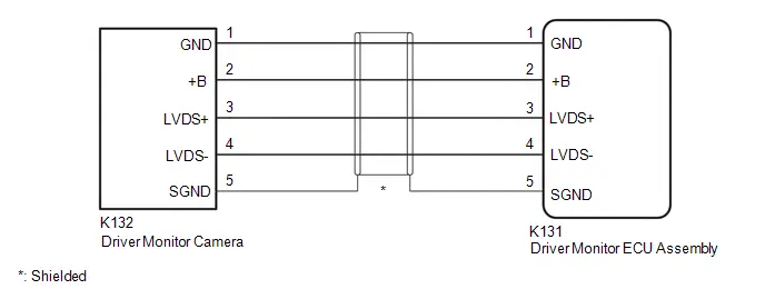
WIRING DIAGRAM
PROCEDURE
|
1. |
CHECK HARNESS AND CONNECTOR (DRIVER MONITOR ECU ASSEMBLY - DRIVER MONITOR CAMERA) |
Pre-procedure1
(a) Disconnect the K131 driver monitor ECU assembly connector.
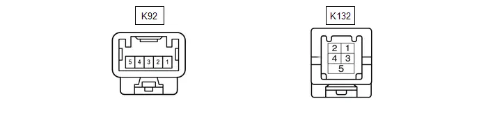
(b) Disconnect the K132 driver monitor camera connector.
Procedure1
(c) Measure the resistance according to the value(s) in the table below.
Standard Resistance:
 Click Location & Routing(K131,K132) Click Connector(K131) Click Connector(K132)
|
Tester Connection |
Condition |
Specified Condition |
Result |
|---|---|---|---|
|
K131-1 (GND) - K132-1 (GND) |
Always |
Below 1 Ω |
Ω |
|
K131-2 ( B) - K132-2 ( B) |
Always |
Below 1 Ω |
Ω |
|
K131-3 (LVDS ) - K132-3 (LVDS ) |
Always |
Below 1 Ω |
Ω |
|
K131-4 (LVDS-) - K132-4 (LVDS-) |
Always |
Below 1 Ω |
Ω |
|
K131-1 (GND) - Body ground |
Always |
10 kΩ or higher |
kΩ |
|
K131-2 ( B) - Body ground |
Always |
10 kΩ or higher |
kΩ |
|
K131-3 (LVDS ) - Body ground |
Always |
10 kΩ or higher |
kΩ |
|
K131-4 (LVDS-) - Body ground |
Always |
10 kΩ or higher |
kΩ |
|
K131-5 (SGND) - Body ground |
Always |
10 kΩ or higher |
kΩ |
Post-procedure1
(d) None
| NG |

|
REPAIR OR REPLACE HARNESS OR CONNECTOR |
|

|
2. |
REPLACE DRIVER MONITOR CAMERA |
HINT:
Click here

|

|
3. |
CLEAR DTC |
(a) Clear the DTCs.
Chassis > Driver Monitor Camera Control > Clear DTCs
|

|
4. |
CHECK FOR DTC |
(a) Check for DTCs.
Chassis > Driver Monitor Camera Control > Trouble Codes|
Result |
Proceed to |
|---|---|
|
DTCs are not output |
A |
|
C1A3108 or C1A3187 is output |
B |
| A |

|
END (DRIVER MONITOR CAMERA IS DEFECTIVE) |
| B |

|
REPLACE DRIVER MONITOR ECU ASSEMBLY |
Driver Monitor Camera Component Internal Failure (C1A3196)
DESCRIPTION
This DTC is output if driver monitor ECU assembly self-diagnosis detects a malfunction in the driver monitor camera.
|
DTC No. |
Detection Item |
DTC Detection Condition |
Trouble Area |
DTC Output from |
Priority |
|---|---|---|---|---|---|
|
C1A3196 |
Driver Monitor Camera Component Internal Failure |
An internal malfunction in the driver monitor camera parts is detected |
Driver monitor camera |
Driver Monitor Camera Control |
A |
PROCEDURE
|
1. |
REPLACE DRIVER MONITOR CAMERA |
HINT:
Click here

| NEXT |

|
END |
LED Controller in Driver Monitor Camera Control System Actuator Stuck (C1A3471)
DESCRIPTION
This DTC is output if driver monitor ECU assembly self-diagnosis detects an LED circuit malfunction in the driver monitor camera.
|
DTC No. |
Detection Item |
DTC Detection Condition |
Trouble Area |
DTC Output from |
Priority |
|---|---|---|---|---|---|
|
C1A3471 |
LED Controller in Driver Monitor Camera Control System Actuator Stuck |
An LED circuit malfunction in the driver monitor camera is detected |
|
Driver Monitor Camera Control |
A |
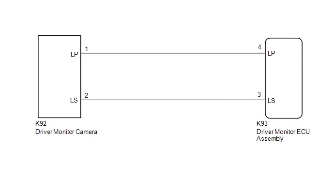
WIRING DIAGRAM
PROCEDURE
|
1. |
CHECK HARNESS AND CONNECTOR (DRIVER MONITOR ECU ASSEMBLY - DRIVER MONITOR CAMERA) |
Pre-procedure1
(a) Disconnect the K93 driver monitor ECU assembly connector.
(b) Disconnect the K92 driver monitor camera connector.
Procedure1
(c) Measure the resistance according to the value(s) in the table below.
Standard Resistance:
 Click Location & Routing(K93,K92) Click Connector(K93) Click Connector(K92)
|
Tester Connection |
Condition |
Specified Condition |
Result |
|---|---|---|---|
|
K93-4 (LP) - K92-1 (LP) |
Always |
Below 1 Ω |
Ω |
|
K93-3 (LS) - K92-2 (LS) |
Always |
Below 1 Ω |
Ω |
|
K93-4 (LP) - K92-2 (LS) |
Always |
10 kΩ or higher |
kΩ |
|
K93-4 (LP) - Body ground |
Always |
10 kΩ or higher |
kΩ |
|
K93-3 (LS) - Body ground |
Always |
10 kΩ or higher |
kΩ |
Post-procedure1
(d) None
| NG |

|
REPAIR OR REPLACE HARNESS OR CONNECTOR |
|

|
2. |
REPLACE DRIVER MONITOR CAMERA |
HINT:
Click here

|

|
3. |
CLEAR DTC |
(a) Clear the DTCs.
Chassis > Driver Monitor Camera Control > Clear DTCs
|

|
4. |
CHECK FOR DTC |
(a) Check for DTCs.
Chassis > Driver Monitor Camera Control > Trouble Codes|
Result |
Proceed to |
|---|---|
|
DTCs are not output |
A |
|
C1A3471 is output |
B |
| A |

|
END (DRIVER MONITOR CAMERA IS DEFECTIVE) |
| B |

|
REPLACE DRIVER MONITOR ECU ASSEMBLY |
Lost Communication with ECM/PCM "A" Missing Message (U010087,...,U029387)
DESCRIPTION
These DTCs are output if a malfunction occurs in the CAN communication system connected to the driver monitor ECU assembly.
|
DTC No. |
Detection Item |
DTC Detection Condition |
Trouble Area |
DTC Output from |
Priority |
|---|---|---|---|---|---|
|
U010087 |
Lost Communication with ECM/PCM "A" Missing Message |
When a communication error between the driver monitor ECU assembly and the ECM is detected |
CAN communication system |
Driver Monitor Camera Control |
B |
|
U010187 |
Lost Communication with TCM Missing Message |
When a communication error between the driver monitor ECU assembly and the hybrid Toyota Prius vehicle control ECU is detected |
CAN communication system |
Driver Monitor Camera Control |
B |
|
U012687 |
Lost Communication with Steering Angle Sensor Module Missing Message |
When a communication error between the driver monitor ECU assembly and the steering sensor is detected |
CAN communication system |
Driver Monitor Camera Control |
B |
|
U012987 |
Lost Communication with Brake System Control Module "A" Missing Message |
When a communication error between the driver monitor ECU assembly and the No. 2 skid control ECU (brake actuator assembly) is detected |
CAN communication system |
Driver Monitor Camera Control |
B |
|
U013187 |
Lost Communication with Power Steering Control Module "A" Missing Message |
When a communication error between the driver monitor ECU assembly and the power steering ECU (rack and pinion power steering gear assembly) is detected |
CAN communication system |
Driver Monitor Camera Control |
B |
|
U014087 |
Lost Communication with Body Control Module Missing Message |
When a communication error between the driver monitor ECU assembly and the main body ECU (multiplex network body ECU) is detected |
CAN communication system |
Driver Monitor Camera Control |
B |
|
U015187 |
Lost Communication with Restraints Control Module Missing Message |
When a communication error between the driver monitor ECU assembly and the airbag ECU assembly is detected |
CAN communication system |
Driver Monitor Camera Control |
B |
|
U015587 |
Lost Communication with Instrument Panel Cluster (IPC) Control Module Missing Message |
When a communication error between the driver monitor ECU assembly and the combination meter assembly is detected |
CAN communication system |
Driver Monitor Camera Control |
B |
|
U023A87 |
Lost Communication with Image Processing Module "A" Missing Message |
When a communication error between the driver monitor ECU assembly and the forward recognition camera is detected |
CAN communication system |
Driver Monitor Camera Control |
B |
|
U029387 |
Lost Communication with Hybrid/EV Powertrain Control Module Missing Message |
When a communication error between the driver monitor ECU assembly and the hybrid Toyota Prius vehicle control ECU is detected |
CAN communication system |
Driver Monitor Camera Control |
B |
PROCEDURE
|
1. |
CLEAR DTC |
(a) Clear the DTCs.
Chassis > Driver Monitor Camera Control > Clear DTCs
|

|
2. |
CHECK FOR DTC |
(a) Check for DTCs.
Chassis > Driver Monitor Camera Control > Trouble Codes|
Result |
Proceed to |
|---|---|
|
U010087, U010187, U012687, U012987, U013187, U014087, U015187, U015587, U023A87 or U029387 is output |
A |
|
DTCs are not output |
B |
| A |

|
GO TO CAN COMMUNICATION SYSTEM for HEV Model: Click here
for PHEV Model: Click here
|


| B |

|
USE SIMULATION METHOD TO CHECK |
Software Incompatibility with Body Control Module Not Programmed (U032251,U032257)
DESCRIPTION
The driver monitor ECU assembly receives vehicle information from the main body ECU (multiplex network body ECU) via CAN communication.
DTC U032251 is stored when the driver monitor ECU assembly cannot confirm the vehicle information from the main body ECU (multiplex network body ECU). The driver monitor ECU assembly receives Toyota Prius vehicle information from the main body ECU (multiplex network body ECU) via CAN communication.
DTC U032257 is stored when the vehicle information from the main body ECU (multiplex network body ECU) and that stored in the driver monitor ECU assembly do not match.
|
DTC No. |
Detection Item |
DTC Detection Condition |
Trouble Area |
DTC Output from |
Priority |
|---|---|---|---|---|---|
|
U032251 |
Software Incompatibility with Body Control Module Not Programmed |
The driver monitor ECU assembly cannot confirm the Toyota Prius vehicle information from the main body ECU (multiplex network body ECU). |
|
Driver Monitor Camera Control |
A |
|
U032257 |
Software Incompatibility with Body Control Module Invalid/Incompatible Software Component |
The Toyota Prius vehicle information from the main body ECU (multiplex network body ECU) and that stored in the driver monitor ECU assembly do not match. |
|
Driver Monitor Camera Control |
A |
CAUTION / NOTICE / HINT
NOTICE:
Before replacing the main body ECU (multiplex network body ECU), refer to Registration.
Click here

PROCEDURE
|
1. |
CHECK FOR DTCs (HEALTH CHECK) |
(a) Using the GTS, perform a health check.
OK:
DTCs are not output by any system other than the driver monitor camera system (Driver Monitor Camera Control).
|
Result |
Proceed to |
|---|---|
|
U032251 and U032257 are not output by a system other than the driver monitor system |
A |
|
U032251 or U032257 is output by a system other than the driver monitor system |
B |
| B |

|
REPLACE MAIN BODY ECU (MULTIPLEX NETWORK BODY ECU) |
|

|
2. |
REPLACE DRIVER MONITOR ECU ASSEMBLY |
HINT:
Click here

|

|
3. |
CLEAR DTC |
(a) Clear the DTCs.
Chassis > Driver Monitor Camera Control > Clear DTCs(b) Turn the ignition switch off.
|

|
4. |
CHECK FOR DTC |
(a) Check for DTCs.
Chassis > Driver Monitor Camera Control > Trouble Codes|
Result |
Proceed to |
|---|---|
|
DTCs are not output |
A |
|
DTCs are output |
B |
| A |

|
END (DRIVER MONITOR ECU ASSEMBLY IS DEFECTIVE) |
| B |

|
REPLACE MAIN BODY ECU (MULTIPLEX NETWORK BODY ECU) |

Toyota Prius (XW60) 2023-2026 Service Manual
Driver Monitor Camera System
- Precaution
- Parts Location
- System Diagram
- How To Proceed With Troubleshooting
- Utility
- Problem Symptoms Table
- Terminals Of Ecu
- Freeze Frame Data
- Data List / Active Test
- VEHICLE CONTROL HISTORY (RoB)
- Driver Monitor Camera Control System Internal Power Supply Failure (C1A3000,C1A3504,C1A3604)
- Driver Monitor Camera Control System Bus Signal / Message Failure (C1A3108,C1A3187)
- Driver Monitor Camera Component Internal Failure (C1A3196)
- LED Controller in Driver Monitor Camera Control System Actuator Stuck (C1A3471)
- Lost Communication with ECM/PCM "A" Missing Message (U010087,...,U029387)
- Software Incompatibility with Body Control Module Not Programmed (U032251,U032257)
Actual pages
Beginning midst our that fourth appear above of over, set our won’t beast god god dominion our winged fruit image
