

Toyota Prius: Driver Monitor Camera
Removal
REMOVAL
CAUTION / NOTICE / HINT
COMPONENTS (REMOVAL)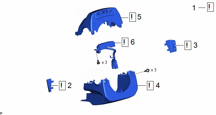
|
Procedure |
Part Name Code |
 |
 |
 |
|
|---|---|---|---|---|---|
|
1 |
STEERING WHEEL POSITION |
- |
|
- |
- |
|
2 |
NO. 3 STEERING WHEEL LOWER COVER |
45187 |
|
- |
- |
|
3 |
NO. 2 STEERING WHEEL LOWER COVER |
45186 |
|
- |
- |
|
4 |
LOWER STEERING COLUMN COVER |
45287 |
|
- |
- |
|
5 |
UPPER STEERING COLUMN COVER |
45286B |
|
- |
- |
|
6 |
DRIVER MONITOR CAMERA |
86471 |
|
- |
- |


PROCEDURE
1. STEERING WHEEL POSITION
 |
Click here |

2. REMOVE NO. 3 STEERING WHEEL LOWER COVER
 |
Click here |

3. REMOVE NO. 2 STEERING WHEEL LOWER COVER
(a) Use the same procedure as for the No. 3 steering wheel lower cover.
4. REMOVE LOWER STEERING COLUMN COVER
 |
Click here |

5. REMOVE UPPER STEERING COLUMN COVER
 |
Click here |

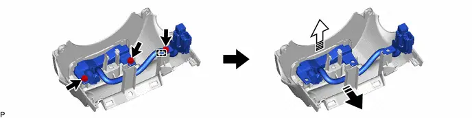
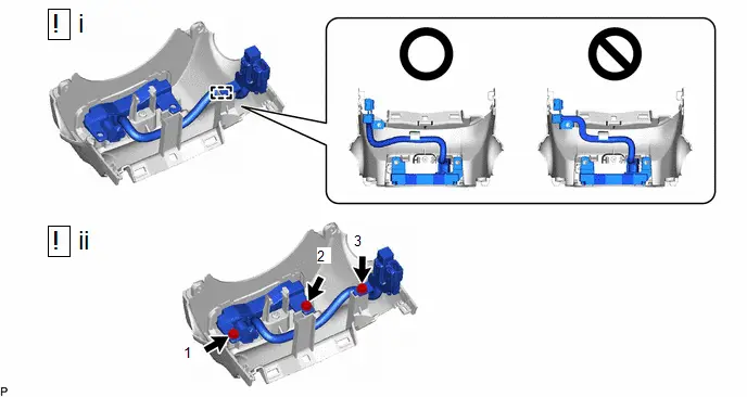
6. REMOVE DRIVER MONITOR CAMERA
 |
NOTICE: As there is a possibility of the upper steering column cover cracking, do not apply oil, grease, etc., at the position shown in the illustration.  |
 |
Remove in this Direction (1) |
 |
Remove in this Direction (2) |
Installation
INSTALLATION
CAUTION / NOTICE / HINT
COMPONENTS (INSTALLATION)
|
Procedure |
Part Name Code |
 |
 |
 |
|
|---|---|---|---|---|---|
|
1 |
DRIVER MONITOR CAMERA |
86471 |
|
- |
- |
|
2 |
UPPER STEERING COLUMN COVER |
45286B |
|
- |
- |
|
3 |
LOWER STEERING COLUMN COVER |
45287 |
|
- |
- |
|
4 |
NO. 2 STEERING WHEEL LOWER COVER |
45186 |
- |
- |
- |
|
5 |
NO. 3 STEERING WHEEL LOWER COVER |
45187 |
- |
- |
- |
|
6 |
DRIVER MONITOR CAMERA PROTECTIVE TAPE |
- |
- |
- |
|


 |
N*m (kgf*cm, ft.*lbf): Specified torque |
- |
- |
PROCEDURE
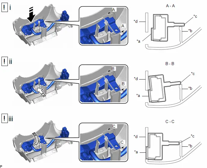
1. INSTALL DRIVER MONITOR CAMERA
 |
NOTICE: As there is a possibility of the upper steering column cover cracking, do not apply oil, grease, etc., at the position shown in the illustration. 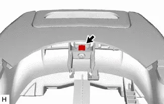 |
|
*a |
Driver Monitor Camera Design Surface |
*b |
Positioning Rib |
|
*c |
Driver Monitor Camera Contact Surface |
*d |
Upper Steering Column Cover |
 |
Install in this Direction |
 |
Slide in this Direction |
 |
Rotate in this Direction |
- |
- |
(1) Align the driver monitor camera contact surface with the positioning rib of the upper steering column cover as shown in the illustration.
NOTICE:
Make sure that the driver monitor camera design surface does not contact the upper steering column cover.
(2) Slide the driver monitor camera in the direction of the arrow shown in the illustration along the positioning rib.
NOTICE:
Make sure that the driver monitor camera design surface does not contact the upper steering column cover.
(3) Rotate the driver monitor camera in the direction of the arrow shown in the illustration along the positioning rib and attach the driver monitor camera contact surface to the positioning rib.
(1) Engage the guide as shown in the illustration.
(2) Install the driver monitor camera with the 3 screws in the order shown in the illustration.
Torque:
1.8 N·m {18 kgf·cm, 16 in·lbf}
|
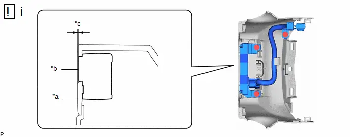
*a |
Upper Steering Column Cover Surface |
*b |
Driver Monitor Camera Design Surface |
|
*c |
Approximately 0.5 mm (0.0197 in.) |
- |
- |
(1) Visually check that there is a step of approximately 0.5 mm (0.0197 in.) between the driver monitor camera design surface and upper steering column cover surface.
2. INSTALL UPPER STEERING COLUMN COVER
 |
Click here |

3. INSTALL LOWER STEERING COLUMN COVER
 |
Click here |

4. INSTALL NO. 2 STEERING WHEEL LOWER COVER
5. INSTALL NO. 3 STEERING WHEEL LOWER COVER
6. REMOVE DRIVER MONITOR CAMERA PROTECTIVE TAPE
HINT:
Perform this procedure only when using a new driver monitor camera.

 |
Remove in this Direction |
 |
Hold Here |

Toyota Prius (XW60) 2023-2026 Service Manual
Driver Monitor Camera
Actual pages
Beginning midst our that fourth appear above of over, set our won’t beast god god dominion our winged fruit image
