

Toyota Prius: Automatic High Beam System
- Parts Location
- How To Proceed With Troubleshooting
- Problem Symptoms Table
- Automatic High Beam Switch Circuit
- Automatic High Beam Switch Indicator does not Come ON
Parts Location
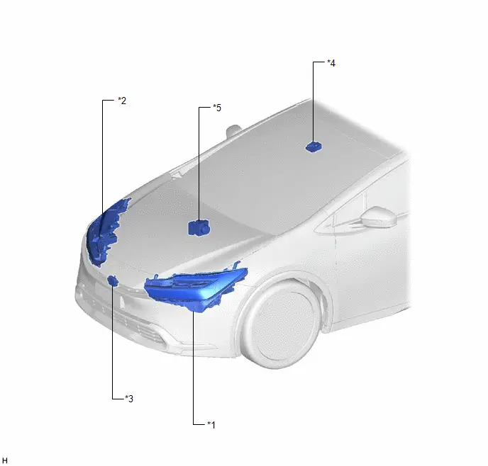
PARTS LOCATION
ILLUSTRATION
|
*1 |
HEADLIGHT ASSEMBLY LH |
*2 |
HEADLIGHT ASSEMBLY RH |
|
*3 |
MILLIMETER WAVE RADAR SENSOR ASSEMBLY |
*4 |
FORWARD RECOGNITION CAMERA |
|
*5 |
NO. 2 SKID CONTROL ECU (BRAKE ACTUATOR ASSEMBLY) |
- |
- |
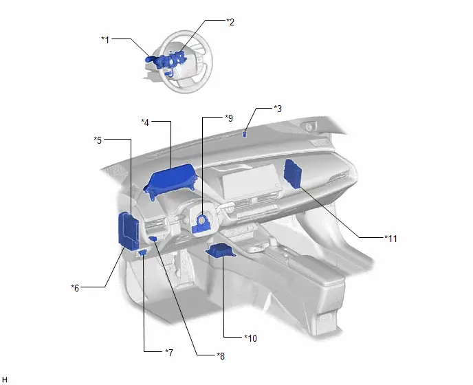
ILLUSTRATION
|
*1 |
TURN SIGNAL SWITCH |
*2 |
STEERING WHEEL SWITCH HOUSING |
|
*3 |
AUTOMATIC LIGHT CONTROL SENSOR |
*4 |
COMBINATION METER ASSEMBLY |
|
*5 |
MAIN BODY ECU (MULTIPLEX NETWORK BODY ECU) |
*6 |
POWER DISTRIBUTION BOX ASSEMBLY - ECU-B NO. 2 FUSE |
|
*7 |
DLC3 |
*8 |
AUTO HIGH BEAM SWITCH |
|
*9 |
STEERING SENSOR |
*10 |
AIRBAG ECU ASSEMBLY |
|
*11 |
HYBRID Toyota Prius Vehicle CONTROL ECU |
- |
- |
How To Proceed With Troubleshooting
CAUTION / NOTICE / HINT
HINT:
- Use the following procedure to troubleshoot the automatic high beam system.
- *: Use the GTS.
PROCEDURE
|
1. |
Toyota Prius Vehicle BROUGHT TO WORKSHOP |
|

|
2. |
CUSTOMER PROBLEM ANALYSIS |
HINT:
- In troubleshooting, confirm that the problem symptoms have been accurately identified. Preconceptions should be discarded in order to make an accurate judgment. To clearly understand what the problem symptoms are, it is extremely important to ask the customer about the problem and the conditions at the time the malfunction occurred.
- Gather as much information as possible for reference. Past problems that seem unrelated may also help in some cases.
- The following 5 items are important points for problem analysis:
What
Toyota Prius Vehicle model, system name
When
Date, time, occurrence frequency
Where
Road conditions
Under what conditions?
Driving conditions, weather conditions
How did it happen?
Problem symptoms
|

|
3. |
PRE-CHECK |
(a) Measure the auxiliary battery voltage with the ignition switch off.
Standard Voltage:
11 to 14 V
If the voltage is below 11 V, recharge or replace the auxiliary battery before proceeding to the next step.
(b) Check the fuses and relays.
(c) Check the connector connections and terminals to make sure that there are no abnormalities such as loose connections, deformation, etc.
|

|
4. |
CHECK COMMUNICATION FUNCTION OF CAN COMMUNICATION SYSTEM* |
(a) Using the GTS, check for CAN communication system DTCs.
Click here

|
Result |
Proceed to |
|---|---|
|
CAN DTCs are not output |
A |
|
CAN DTCs are output |
B |
| B |

|
GO TO CAN COMMUNICATION SYSTEM |
|

|
5. |
CHECK FOR DTC* |
(a) Check for DTCs.
Body Electrical > Main Body > Trouble Codes|
Result |
Proceed to |
|---|---|
|
DTCs are not output |
A |
|
DTCs are output |
B |
| B |

|
GO TO DIAGNOSTIC TROUBLE CODE CHART |
|

|
6. |
CHECK FOR DTC* |
(a) Check for DTCs.
Chassis > Front Recognition Camera > Trouble Codes|
Result |
Proceed to |
|---|---|
|
DTCs are not output |
A |
|
DTCs are output |
B |
| B |

|
GO TO DIAGNOSTIC TROUBLE CODE CHART |
|

|
7. |
CHECK Toyota Prius Vehicle CONTROL HISTORY* |
(a) Using the GTS, check for Vehicle Control History (RoB).
Chassis > Front Recognition Camera > Utility|
Tester Display |
|---|
|
Toyota Prius Vehicle Control History (RoB) |
NOTICE:
Make sure to record the output Vehicle Control History.
|
Result |
Proceed to |
|---|---|
|
Toyota Prius Vehicle Control History codes are not output |
A |
|
Vehicle Control History codes are output |
B |
| B |

|
GO TO Toyota Prius Vehicle CONTROL HISTORY |
|

|
8. |
PROBLEM SYMPTOMS TABLE |
(a) Refer to Problem Symptoms Table.
Click here

|
Result |
Proceed to |
|---|---|
|
Fault is not listed in Problem Symptoms Table |
A |
|
Fault is listed in Problem Symptoms Table |
B |
| B |

|
GO TO PROBLEM SYMPTOMS TABLE |
|

|
9. |
OVERALL ANALYSIS AND TROUBLESHOOTING* |
(a) Operation Check.
Click here

(b) Terminals of ECU.
Click here

(c) Data List / Active Test.
Click here

(d) On-Toyota Prius vehicle Inspection.
(e) Inspection.
|

|
10. |
ADJUST, REPAIR OR REPLACE |
|

|
11. |
CONFIRMATION TEST |
| NEXT |

|
END |
Problem Symptoms Table
PROBLEM SYMPTOMS TABLE
NOTICE:
- When replacing the forward recognition camera, replace it with a new one. If a forward recognition camera which was installed to another vehicle is used, the information stored in the forward recognition camera will not match the information from the Toyota Prius vehicle and a DTC may be stored.
- When the forward recognition camera has been replaced with a new one,
make sure to clear all stored vehicle control history of each system and
the forward recognition camera beam axis alignment data.
HINT:
Forward recognition camera beam axis alignment can be performed by using "One Time Recognition", "Driving Adjustment" or "Camera Axis Adjustment Value Write".
One Time Recognition: Click here

Driving Adjustment: Click here

Camera Axis Adjustment Value Write: Click here

- If the forward recognition camera has been replaced with a new one,
make sure to perform Software Version Confirmation.
Click here

- When replacing the millimeter wave radar sensor assembly, always replace it with a new one. If a millimeter wave radar sensor assembly which was installed to another Toyota Prius vehicle is used, the information stored in the millimeter wave radar sensor assembly will not match the information from the vehicle and a DTC may be stored.
- When the millimeter wave radar sensor assembly has been replaced with
a new one, it is necessary to perform millimeter wave radar sensor assembly
beam axis alignment and to clear the Toyota Prius vehicle control history.
Before performing the Driving Adjustment, make sure to read Before Starting
Driving Adjustment.
HINT:
Beam axis alignment of the millimeter wave radar sensor assembly can be performed using either Triangle Target, Flat Surface Target or Driving Adjustment.
Triangle Target: Click here

Flat Surface Target: Click here

Driving Adjustment: Click here

- When replacing the combination meter assembly, always replace it with a new one. If a combination meter assembly which was installed to another Toyota Prius vehicle is used, the information stored in it will not match the information from the vehicle and a DTC may be stored.
- When replacing the forward recognition camera and combination meter
assembly, update the ECU security key.
Click here

HINT:
Use the table below to help determine the cause of problem symptoms. If multiple suspected areas are listed, the potential causes of the symptoms are listed in order of probability in the "Suspected Area" column of the table. Check each symptom by checking the suspected areas in the order they are listed. Replace parts as necessary.
Automatic High Beam System|
Symptom |
Suspected Area |
Link |
|---|---|---|
|
Automatic high beam indicator on the combination meter assembly does not illuminate |
Check operating conditions |
|
|
Meter/gauge system |

 |
|
|
Automatic high beam switch circuit |
|
|
|
Headlight dimmer switch circuit |
 |
|
|
Combination meter assembly |
 |
|
|
Forward recognition camera |
|
|
|
Main body ECU (Multiplex network body ECU) |

 |
|
|
Automatic high beam system does not operate |
Check operating conditions |
|
|
Check that the low beams and high beams operate manually |
- |
|
|
Check automatic light control system operation |
|
|
|
Automatic high beam switch circuit |
|
|
|
Headlight dimmer switch circuit |
 |
|
|
Forward recognition camera |
|
|
|
Millimeter wave radar sensor assembly |
|
|
|
Main body ECU (Multiplex network body ECU) |
|
|
|
Automatic high beam switch indicator does not come ON |
Refer to "Automatic High Beam Switch Indicator does not Come ON" |
|


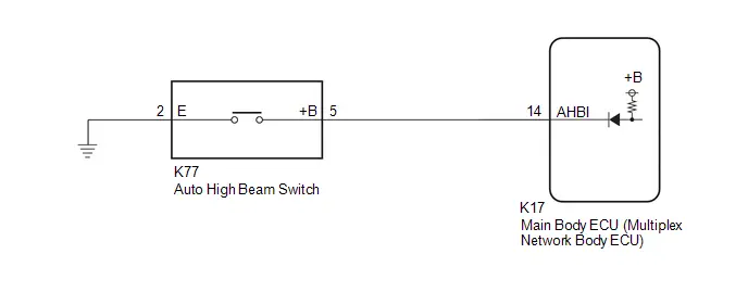
Automatic High Beam Switch Circuit
DESCRIPTION
The main body ECU (multiplex network body ECU) detects the ON/OFF signal of the auto high beam switch.
WIRING DIAGRAM
CAUTION / NOTICE / HINT
NOTICE:
Before replacing the main body ECU (multiplex network body ECU), refer to Registration.
Click here

PROCEDURE
|
1. |
READ VALUE USING GTS |
(a) Read the Data List according to the display on the GTS.
Body Electrical > Main Body > Data List|
Tester Display |
Measurement Item |
Range |
Normal Condition |
Diagnostic Note |
|---|---|---|---|---|
|
Auto High Beam Main Switch |
Auto high beam switch signal |
OFF or ON |
OFF: Auto high beam switch not pressed ON: Auto high beam switch pressed |
- |
|
Tester Display |
|---|
|
Auto High Beam Main Switch |
OK:
Normal conditions listed above are displayed.
| OK |

|
PROCEED TO NEXT SUSPECTED AREA SHOWN IN PROBLEM SYMPTOMS TABLE |
|

|
2. |
INSPECT AUTO HIGH BEAM SWITCH |
Click here

| NG |

|
REPLACE AUTO HIGH BEAM SWITCH |
|

|
3. |
CHECK HARNESS AND CONNECTOR (AUTO HIGH BEAM SWITCH - MAIN BODY ECU (MULTIPLEX NETWORK BODY ECU) AND BODY GROUND) |
(a) Disconnect the K17 main body ECU (multiplex network body ECU) connector.
(b) Measure the resistance according to the value(s) in the table below.
Standard Resistance:
 Click
Location & Routing(K77,K17) Click Connector(K77) Click Connector(K17)
Click
Location & Routing(K77,K17) Click Connector(K77) Click Connector(K17)
|
Tester Connection |
Condition |
Specified Condition |
|---|---|---|
|
K77-5 ( B) - K17-14 (AHBI) |
Always |
Below 1 Ω |
|
K77-5 ( B) or K17-14 (AHBI) - Body ground |
Always |
10 kΩ or higher |
|
K77-2 (E) - Body ground |
Always |
Below 1 Ω |
| OK |

|
REPLACE MAIN BODY ECU (MULTIPLEX NETWORK BODY ECU)
|


| NG |

|
REPAIR OR REPLACE HARNESS OR CONNECTOR |
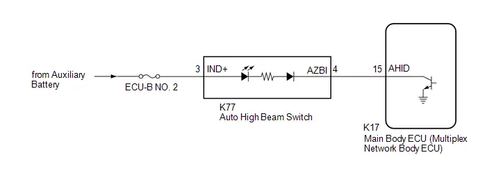
Automatic High Beam Switch Indicator does not Come ON
DESCRIPTION
When the automatic high beam system is on, the main body ECU (multiplex network body ECU) illuminates the auto high beam switch indicator.
WIRING DIAGRAM
CAUTION / NOTICE / HINT
NOTICE:
- Inspect the fuses for circuits related to this system before performing the following procedure.
- Before replacing the main body ECU (multiplex network body ECU), refer
to Registration.
Click here

PROCEDURE
|
1. |
READ VALUE USING GTS |
(a) Read the Data List according to the display on the GTS.
Body Electrical > Main Body > Active Test|
Tester Display |
Measurement Item |
Control Range |
Diagnostic Note |
|---|---|---|---|
|
Automatic High Beam Switch Light |
Auto high beam switch indicator light |
OFF or ON |
- |
|
Tester Display |
|---|
|
Automatic High Beam Switch Light |
OK:
Normal conditions listed above are displayed.
| OK |

|
USE SIMULATION METHOD TO CHECK |
|

|
2. |
INSPECT AUTO HIGH BEAM SWITCH |
Click here

| NG |

|
REPLACE AUTO HIGH BEAM SWITCH |
|

|
3. |
CHECK HARNESS AND CONNECTOR (POWER SOURCE - AUTO HIGH BEAM SWITCH) |
(a) Measure the voltage according to the value(s) in the table below.
Standard Voltage:
 Click Location & Routing(K77) Click Connector(K77)
|
Tester Connection |
Condition |
Specified Condition |
|---|---|---|
|
K77-3 (IND ) - Body ground |
Ignition switch off |
11 to 14 V |
| NG |

|
REPAIR OR REPLACE HARNESS OR CONNECTOR |
|

|
4. |
CHECK HARNESS AND CONNECTOR (AUTO HIGH BEAM SWITCH - MAIN BODY ECU (MULTIPLEX NETWORK BODY ECU)) |
(a) Disconnect the K17 main body ECU (multiplex network body ECU) connector.
(b) Measure the resistance according to the value(s) in the table below.
Standard Resistance:
 Click Location & Routing(K77,K17) Click Connector(K77) Click Connector(K17)
|
Tester Connection |
Condition |
Specified Condition |
|---|---|---|
|
K77-4 (AZBI) - K17-15 (AHID) |
Always |
Below 1 Ω |
|
K77-4 (AZBI) or K17-15 (AHID) - Body ground |
Always |
10 kΩ or higher |
| OK |

|
REPLACE MAIN BODY ECU (MULTIPLEX NETWORK BODY ECU)
|


| NG |

|
REPAIR OR REPLACE HARNESS OR CONNECTOR |

Toyota Prius (XW60) 2023-2026 Service Manual
Automatic High Beam System
- Parts Location
- How To Proceed With Troubleshooting
- Problem Symptoms Table
- Automatic High Beam Switch Circuit
- Automatic High Beam Switch Indicator does not Come ON
Actual pages
Beginning midst our that fourth appear above of over, set our won’t beast god god dominion our winged fruit image
