

Toyota Prius: Digital Inner Mirror
On-vehicle Inspection
ON-VEHICLE INSPECTION
PROCEDURE
1. INSPECT INNER REAR VIEW MIRROR ASSEMBLY
NOTICE:
- Perform this inspection indoors.
- When anti-glare is not operating, the mirror surface is bright. When anti-glare is operating, the mirror surface is darkened.
Pre-procedure1
(a) Turn the ignition switch to ON.
Procedure1
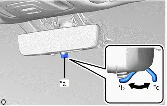
| (b) Confirm that the mode selection lever is set to the optical mirror mode side. HINT: If the mode selection lever is set to the digital mirror mode side, move it to the optical mirror mode side. |
|
| (c) Operate the menu switch and confirm that the cursor is in the location shown in the illustration and that anti-glare is not operating. HINT:
|
|
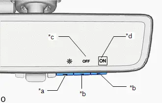
| (d) Using the menu switch and cursor operation switches, turn off automatic anti-glare mode. HINT: When automatic anti-glare mode is off, anti-glare does not operate regardless of the ambient conditions. |
|
(e) Using the menu switch and cursor operation switches, turn on automatic anti-glare mode.
(f) While covering the ambient light sensor with your hand, shine a light on the rearward facing light sensor and confirm that anti-glare operates.
(g) Remove your hand from the sensor and stop shining the light at the rearward facing light sensor and confirm that anti-glare stops operating.
NOTICE:
If the system does not operate as indicated above, perform the test several times with the digital inner mirror at different angles or with different ambient conditions.
Post-procedure1
(h) None
Removal
REMOVAL
CAUTION / NOTICE / HINT
The necessary procedures (adjustment, calibration, initialization or registration) that must be performed after parts are removed and installed, or replaced during inner rear view mirror assembly removal/installation are shown below.
Necessary Procedure After Parts Removed/Installed/Replaced| Replaced Part or Performed Procedure | Necessary Procedure | Effect/Inoperative Function When Necessary Procedures are not Performed | Link |
|---|---|---|---|
| Inner rear view mirror assembly | Register codes in the garage door opener system | Garage Door Opener System (for Digital Inner Mirror) |
|

CAUTION / NOTICE / HINT
COMPONENTS (REMOVAL)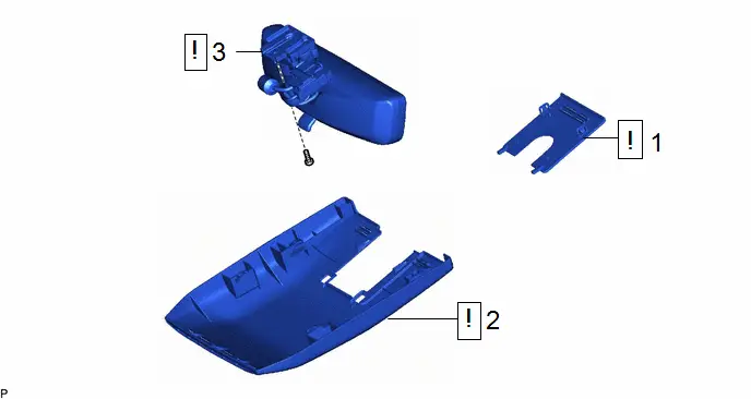
| Procedure | Part Name Code |

|

|

| |
|---|---|---|---|---|---|
| 1 | NO. 2 FORWARD RECOGNITION COVER | 86466E |
| - | - |
| 2 | NO. 1 FORWARD RECOGNITION COVER | 86466D |
| - | - |
| 3 | INNER REAR VIEW MIRROR ASSEMBLY | 87810 |
| - | - |


PROCEDURE
1. REMOVE NO. 2 FORWARD RECOGNITION COVER

| Click here
|


2. REMOVE NO. 1 FORWARD RECOGNITION COVER

| Click here
|


3. REMOVE INNER REAR VIEW MIRROR ASSEMBLY
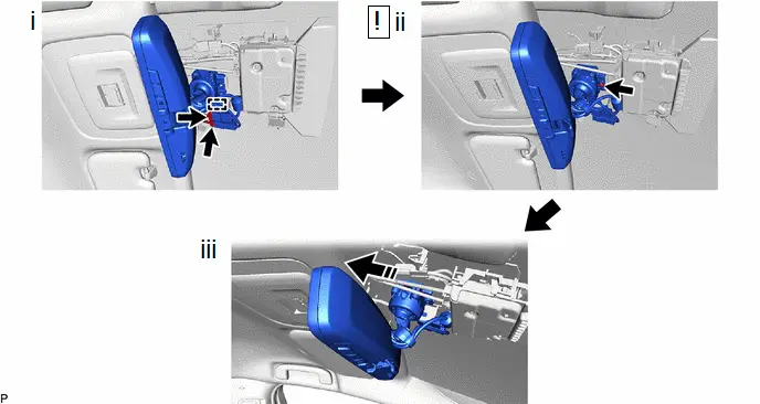

| Remove in this Direction | - | - |
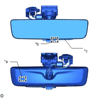
(1) Disengage the clamp and disconnect the 2 connectors.
(2) Using a T20 "TORX" socket wrench, remove the screw.
(3) Slide the inner rear view mirror assembly as shown in the illustration to remove it.
Inspection
INSPECTION
PROCEDURE
1. INSPECT INNER REAR VIEW MIRROR ASSEMBLY
Pre-procedure1
(a) Connect a positive ( ) lead from the auxiliary battery to terminal 1 and terminal 6 and a negative (-) lead to terminal 2.
(b) Confirm that the mode selection lever is set to the mirror surface mode side.
HINT:
If the mode selection lever is set to the digital mirror surface mode side, move it to the mirror surface mode side.
(c) Attach black colored tape to the ambient light sensor to prevent it from sensing.
(d) Using the menu switch and cursor operation switches, turn on automatic anti-glare mode.
Procedure1
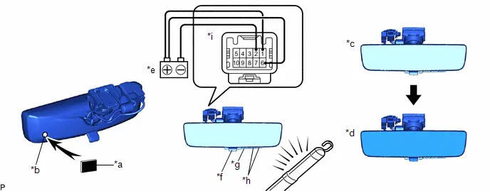
| *a | Black Colored Tape | *b | Ambient Light Sensor |
| *c | Bright | *d | Dark |
| *e | Auxiliary Battery | *f | Mode Selection Lever |
| *g | Menu Switch | *h | Cursor Operation Switch |
| *i | Component without harness connected (Inner Rear View Mirror Assembly) | - | - |
(1) Light up the mirror with an electric light, and check that the mirror surface changes from bright to dark.
OK:
Mirror surface changes from bright to dark.
If the result is not as specified, replace the inner rear view mirror assembly.
Post-procedure1
(f) None
Installation
INSTALLATION
CAUTION / NOTICE / HINT
COMPONENTS (INSTALLATION)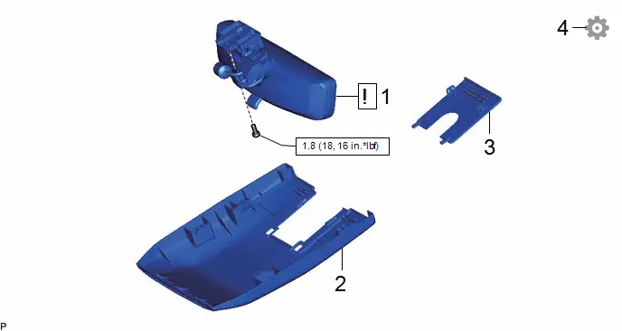
| Procedure | Part Name Code |

|

|

| |
|---|---|---|---|---|---|
| 1 | INNER REAR VIEW MIRROR ASSEMBLY | 87810 |
| - | - |
| 2 | NO. 1 FORWARD RECOGNITION COVER | 86466D | - | - | - |
| 3 | NO. 2 FORWARD RECOGNITION COVER | 86466E | - | - | - |
| 4 | PERFORM REGISTRATION | - | - | - |
|


| N*m (kgf*cm, ft.*lbf): Specified torque | - | - |
PROCEDURE
1. INSTALL INNER REAR VIEW MIRROR ASSEMBLY
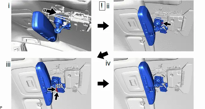

| Install in this Direction | - | - |
(1) Slide and temporarily install the inner rear view mirror assembly as shown in the illustration.
(2) Using a T20 "TORX" socket wrench, install the inner rear view mirror assembly with the screw.
Torque:
1.8 N·m {18 kgf·cm, 16 in·lbf}
(3) Engage the clamp and connect the 2 connectors.
(4) Check that there is no play in the inner rear view mirror assembly.
2. INSTALL NO. 1 FORWARD RECOGNITION COVER
3. INSTALL NO. 2 FORWARD RECOGNITION COVER
4. PERFORM REGISTRATION
Click here


Toyota Prius (XW60) 2023-2026 Service Manual
Digital Inner Mirror
Actual pages
Beginning midst our that fourth appear above of over, set our won’t beast god god dominion our winged fruit image
