

Toyota Prius: Cylinder Head
Precaution
PRECAUTION
HINT:
- Any digits beyond the 0.01 mm (1/1000 in.) place for standard, minimum and maximum values should be used as a reference only.
- When both standard and maximum or minimum values are listed for an inspection, use the standard value as a reference only and base any judgments on the maximum and minimum values.
Disassembly
DISASSEMBLY
CAUTION / NOTICE / HINT
The necessary procedures (adjustment, calibration, initialization or registration) that must be performed after parts are removed and installed, or replaced during engine unit removal/installation are shown below.
Necessary Procedures After Parts Removed/Installed/Replaced| Replaced Part or Performed Procedure | Necessary Procedure | Effect/Inoperative Function when Necessary Procedure not Performed | Link |
|---|---|---|---|
|
*: Even when not replacing the part, it is necessary to perform the specified necessary procedures after installation.
*1: Also necessary after performing a tire rotation. *2: It is not necessary to perform this procedure if the tire pressure warning valve and transmitters are installed to the same location. | |||
| Replacement of ECM | Update ECU security key | Toyota Prius Vehicle Control History (RoB) are stored |
|
| ECU configuration | - |
| |
| Perform Toyota Prius Vehicle Identification Number (VIN) registration | DTC is output |
| |
| Inspection after repair |
|
|
| Replacement of inverter with converter assembly | ECU configuration | - |
|
| Resolver learning |
|
| |
| Replacement of hybrid vehicle transaxle assembly |
|
|
|
| Suspension parts | Rear television camera assembly optical axis (Back camera position setting) | Parking Assist Monitor System |
|
| Parking assist ECU initialization | Panoramic View Monitor System |
| |
| Advanced Park |
| ||
| Tires |
| Tire Pressure Warning System | Refer to Procedures Necessary When Replacing Parts (for Tire Pressure Warning System) table below |
| Rear television camera assembly optical axis (Back camera position setting) | Parking Assist Monitor System |
| |
| Parking assist ECU initialization | Panoramic View Monitor System |
| |
| Advanced Park |
| ||
| Replacement of front bumper assembly* | Front television camera view adjustment | Panoramic View Monitor System |
|
| Advanced Park |
| ||


HINT:
When the cable is disconnected / reconnected to the auxiliary battery terminal, systems temporarily stop operating. However, each system has a function that completes learning the first time the system is used.
-
Learning completes when Toyota Prius vehicle is driven
Effect/Inoperative Function When Necessary Procedures are not Performed
Necessary Procedures
Link
Front Camera System
Drive the Toyota Prius vehicle straight ahead at 35 km/h (22 mph) or more for 5 seconds or more.

-
Learning completes when vehicle is operated normally
Effect/Inoperative Function When Necessary Procedures are not Performed
Necessary Procedures
Link
*1: w/o Power Back Door System *2: w/ Power Back Door System
Power Door Lock Control System*1
- Back door opener
Perform door unlock operation with door control switch or electrical key transmitter sub-assembly switch.

Power Back Door System*2
Reset back door close position

Air Conditioning System
After the ignition switch is turned to ON, the servo motor standard position is recognized.
-
CAUTION / NOTICE / HINT
COMPONENTS (DISASSEMBLY)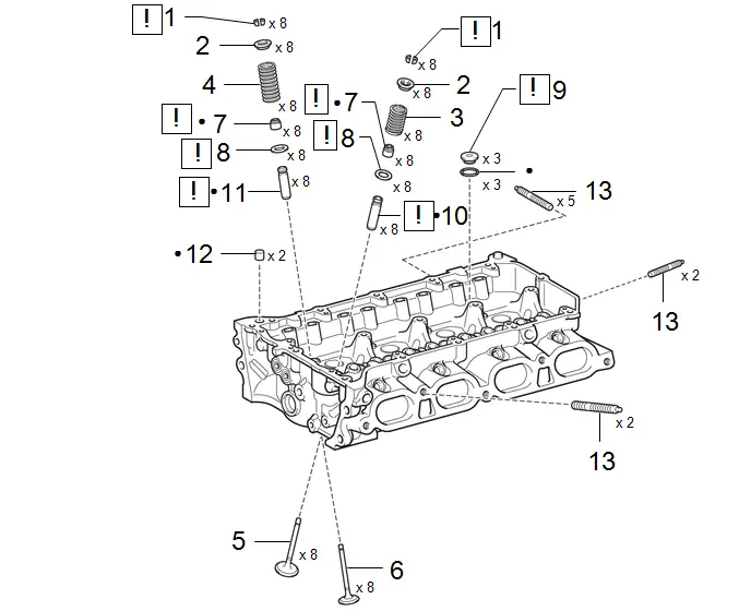
| Procedure | Part Name Code |

|

|

| |
|---|---|---|---|---|---|
| 1 | VALVE SPRING RETAINER ROCK | - |
| - | - |
| 2 | VALVE SPRING RETAINER | - | - | - | - |
| 3 | INTAKE VALVE COMPRESSION SPRING | - | - | - | - |
| 4 | EXHAUST VALVE COMPRESSION SPRING | - | - | - | - |
| 5 | INTAKE VALVE | 13711 | - | - | - |
| 6 | EXHAUST VALVE | 13715 | - | - | - |
| 7 | VALVE STEM OIL SEAL | - |
| - | - |
| 8 | VALVE SPRING SEAT | 13734 |
| - | - |
| 9 | NO. 1 STRAIGHT SCREW PLUG | 11117E |
| - | - |
| 10 | INTAKE VALVE GUIDE BUSH | 11122 |
| - | - |
| 11 | EXHAUST VALVE GUIDE BUSH | 11126 |
| - | - |
| 12 | RING PIN | - | - | - | - |
| 13 | STUD BOLT | - | - | - | - |


| ● | Non-reusable part | - | - |
PROCEDURE
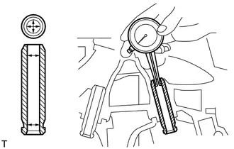
1. REMOVE VALVE SPRING RETAINER ROCK
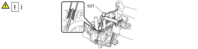
(1) Using SST and wooden blocks, compress the inner compression spring and remove the 16 valve spring retainer locks.
SST: 09202-70020
09202-01010
09202-01020
SST: 09202-00021
2. REMOVE VALVE SPRING RETAINER

3. REMOVE INTAKE VALVE COMPRESSION SPRING

4. REMOVE EXHAUST VALVE COMPRESSION SPRING
(a) Perform the same procedure as for the intake side.
5. REMOVE INTAKE VALVE

6. REMOVE EXHAUST VALVE
(a) Perform the same procedure as for the intake side.
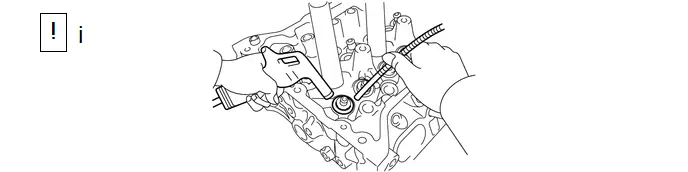
7. REMOVE VALVE STEM OIL SEAL

(1) Using needle-nose pliers, remove the 16 valve stem oil seals.
8. REMOVE VALVE SPRING SEAT
(1) Using compressed air and a Magnet Hand, remove the 16 valve spring seats from the cylinder head sub-assembly by blowing air onto them.
9. REMOVE NO. 1 STRAIGHT SCREW PLUG

| NOTICE: If coolant leaks from a No. 1 straight screw plug or a plug is corroded, replace it. |

(1) Using a 10 mm straight hexagon wrench, remove the 3 No. 1 straight screw plugs and 3 gaskets from the cylinder head sub-assembly.
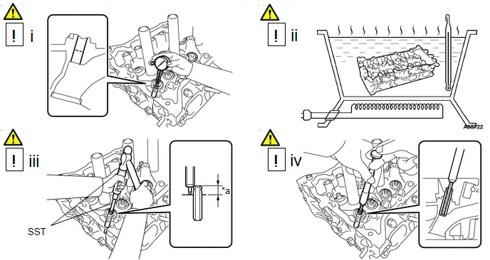
10. REMOVE INTAKE VALVE GUIDE BUSH
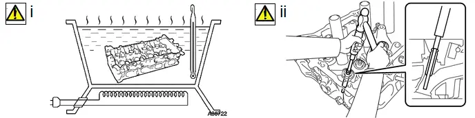
(1) Heat the cylinder head sub-assembly to 80 to 100°C (176 to 212°F).
(2) Using SST and a hammer, tap out the intake valve guide bush.
SST: 09201-10000
09201-01050
SST: 09950-70010
09951-07100
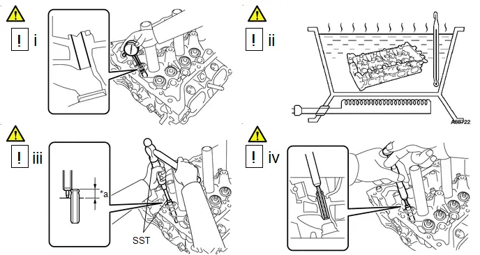
11. REMOVE EXHAUST VALVE GUIDE BUSH
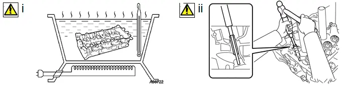
(1) Heat the cylinder head sub-assembly to 80 to 100°C (176 to 212°F).
(2) Using SST and a hammer, tap out the exhaust valve guide bush.
SST: 09201-10000
09201-01050
SST: 09950-70010
09951-07100
12. REMOVE RING PIN

13. REMOVE STUD BOLT
Inspection
INSPECTION
PROCEDURE
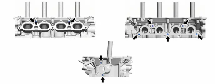
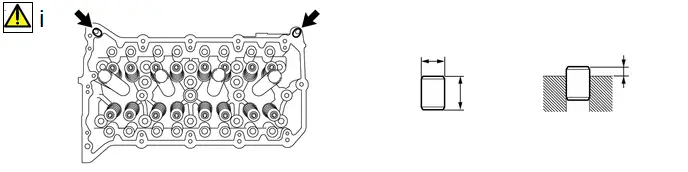
1. INSPECT CYLINDER HEAD SUB-ASSEMBLY FOR WARPAGE
| (a) Using a precision straightedge and feeler gauge, check the surfaces which contact the cylinder head sub-assembly and manifold for warpage. Maximum Warpage:
|
|
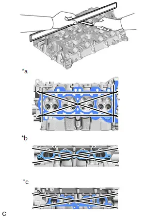
(b) If the warpage is more than the maximum, replace the cylinder head sub-assembly.
2. INSPECT CYLINDER HEAD SUB-ASSEMBLY FOR CRACKS
| (a) Using a dye penetrant, check the intake ports, exhaust ports and bottom surface of the cylinder head sub-assembly for cracks. |
|
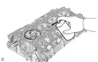
(b) If cracks are found, replace the cylinder head sub-assembly.
3. INSPECT INTAKE VALVE
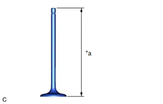
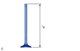
| (a) Using a vernier caliper, measure the overall length of the intake valve. Standard Overall Length:
(1) If the overall length is less than the minimum, replace the intake valve. |
|
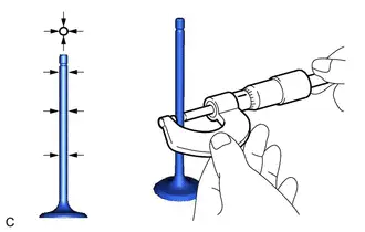
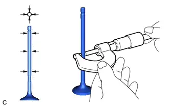
| (b) Using a micrometer, measure the diameter of the valve stem. Standard Valve Stem Diameter:
(1) If the valve stem diameter is not as specified, check the intake valve guide bush oil clearance. HINT: Click here
|
|

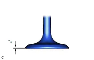
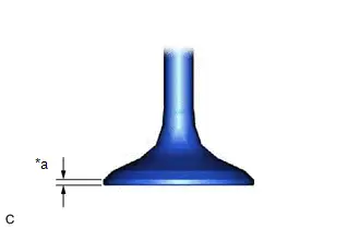
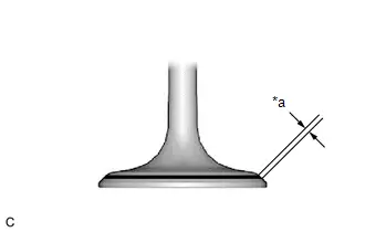
| (c) Using a vernier caliper, measure the valve head margin thickness. Standard Margin Thickness:
(1) If the margin thickness is less than the minimum, replace the intake valve. |
|
4. INSPECT EXHAUST VALVE
| (a) Using a vernier caliper, measure the overall length of the exhaust valve. Standard Overall Length:
(1) If the overall length is less than the minimum, replace the exhaust valve. |
|
| (b) Using a micrometer, measure the diameter of the valve stem. Standard Valve Stem Diameter:
(1) If the valve stem diameter is not as specified, check the exhaust valve guide bush oil clearance. HINT: Click here
|
|

| (c) Using a vernier caliper, measure the valve head margin thickness. Standard Margin Thickness:
(1) If the margin thickness is less than the minimum, replace the exhaust valve. |
|
5. INSPECT INNER COMPRESSION SPRING
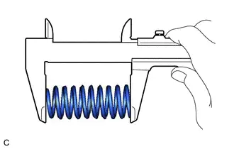
| (a) Using a vernier caliper, measure the free length of the inner compression spring. Standard Free Length:
NOTICE: Inner compression springs come in 2 different lengths. Make sure all inner compression springs are the same length when replacing them. |
|
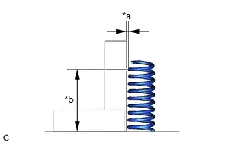
| (b) Using a steel square, measure the angle of the inner compression spring. Maximum Angle (Reference): 2° (1) If the deviation is greater than the maximum, replace the inner compression spring. |
|
6. INSPECT VALVE GUIDE BUSH OIL CLEARANCE
| (a) Using a caliper gauge, measure the inside diameter of the valve guide bush. Standard Valve Guide Bush Inside Diameter:
|
|
(b) Subtract the valve stem diameter measurement from the valve guide bush inside diameter measurement.
Standard Oil Clearance:
| Item | Maximum Oil Clearance | Specified Condition | Result |
|---|---|---|---|
| Intake Side | 0.080 mm 0.00315 in. | 0.025 to 0.060 mm 0.000984 to 0.00236 in. | mm in. |
| Exhaust Side | 0.085 mm 0.00335 in. | 0.030 to 0.065 mm 0.00118 to 0.00256 in. | mm in. |
HINT:
Oil clearance = Inside diameter - Valve stem diameter
(1) If the oil clearance is more than the maximum, replace the valve and valve guide bush.
7. INSPECT VALVE SEATS
Pre-procedure1
| (a) Apply a light coat of Prussian blue to the valve face. |
|
(b) Lightly press the valve face against the valve seat.
NOTICE:
Do not rotate the valve while pressing it.
Procedure1
(c) Check the valve face and valve seat.
(1) If Prussian blue appears 360° around the entire valve face, the valve face is concentric.
(2) If the valve face is not concentric, replace the valve.
(3) If Prussian blue appears 360° around the entire valve seat, the valve seat and valve face are concentric.
(4) If the valve face is not concentric, resurface the valve seat.
HINT:
Click here

(5) Measure the width of the contact area of the valve seat and valve face.
Standard Width:
| Item | Specified Condition | Result |
|---|---|---|
| Intake Side | 1.0 to 1.4 mm 0.0394 to 0.0551 in. | mm in. |
| Exhaust Side | 1.0 to 1.4 mm 0.0394 to 0.0551 in. | mm in. |
Post-procedure1
(d) None
Reassembly
REASSEMBLY
CAUTION / NOTICE / HINT
HINT:
Perform "Inspection After Repair" after replacing the cylinder head sub-assembly.
Click here

CAUTION / NOTICE / HINT
COMPONENTS (REASSEMBLY)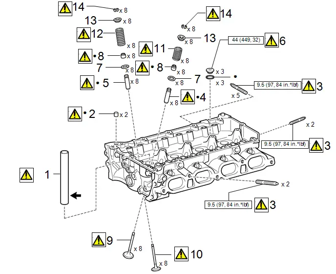
| Procedure | Part Name Code |

|

|

| |
|---|---|---|---|---|---|
| 1 | SPARK PLUG TUBE | - |
| - | - |
| 2 | RING PIN | - |
| - | - |
| 3 | STUD BOLT | - |
| - | - |
| 4 | INTAKE VALVE GUIDE BUSH | 11122 |
| - | - |
| 5 | EXHAUST VALVE GUIDE BUSH | 11126 |
| - | - |
| 6 | NO. 1 STRAIGHT SCREW PLUG | 11117E |
| - | - |
| 7 | VALVE SPRING SEAT | 13734 | - | - | - |
| 8 | VALVE STEM OIL SEAL | - |
| - | - |
| 9 | INTAKE VALVE | 13711 |
| - | - |
| 10 | EXHAUST VALVE | 13715 |
| - | - |
| 11 | INTAKE VALVE COMPRESSION SPRING | - |
| - | - |
| 12 | EXHAUST VALVE COMPRESSION SPRING | - |
| - | - |
| 13 | VALVE SPRING RETAINER | - | - | - | - |
| 14 | VALVE SPRING RETAINER ROCK | - |
| - | - |


| N*m (kgf*cm, ft.*lbf): Specified torque | ● | Non-reusable part |

| Adhesive 1324 | ★ | Precoated part |
PROCEDURE
1. INSTALL SPARK PLUG TUBE

| HINT: When using a new cylinder head sub-assembly, the spark plug tube must be replaced. |
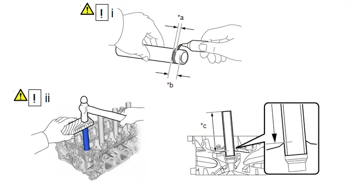
| *a | Application Width | *b | 1.0 to 13.0 mm (0.0394 to 0.512 in.) |
| *c | Protrusion Height | - | - |
(1) Apply adhesive to the area of a new spark plug tube shown in the illustration.
Adhesive:
Toyota Genuine Adhesive 1324, Three Bond 1324 or equivalent
Standard Application Width:
1.0 to 3.0 mm (0.0394 to 0.118 in.)
NOTICE:
- Install the spark plug tube within 3 minutes of applying adhesive.
- Be careful not to deform the spark plug tube.
- Be careful not to expose the adhesive to engine oil for at least 1 hour after installing the spark plug tube.
(2) Using a wooden block and hammer, tap in the spark plug tube to the specified protrusion height.
Standard Protrusion Height:
122 mm (4.80 in.)
NOTICE:
To avoid tapping in the spark plug tube too far, measure the protrusion height while tapping it.
2. INSTALL RING PIN
(1) Using a plastic hammer, tap in 2 new ring pins to the specified protrusion height.
Standard Ring Pin:
| Item | Height | Width | Protrusion Height |
|---|---|---|---|
| Ring pin | 11.7 to 12.3 mm (0.461 to 0.484 in.) | 12.0 mm (0.472 in.) | 6.5 to 7.5 mm (0.256 to 0.295 in.) |
3. INSTALL STUD BOLT
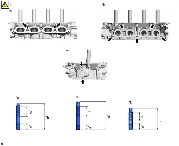
| *a | Intake Manifold Side | *b | Exhaust Manifold Side |
| *c | Cylinder Head Rear Side | *d | 55 mm (2.17 in.) |
| *e | 13 mm (0.512 in.) | *f | 26 mm (1.02 in.) |
| *g | 24 mm (0.945 in.) | *h | 49.5 mm (1.95 in.) |
| *i | 20 mm (0.787 in.) | *j | 42 mm (1.65 in.) |
(1) Using E7 and E8 "TORX" socket wrenches, install the 9 stud bolts to the cylinder head sub-assembly.
Torque:
9.5 N·m {97 kgf·cm, 84 in·lbf}
4. INSTALL INTAKE VALVE GUIDE BUSH
| *a | Height | - | - |
(1) Using a caliper gauge, measure the intake valve guide bush bore diameter of the cylinder head sub-assembly.
Standard Intake Valve Guide Bush Bore Diameter:
10.285 to 10.306 mm (0.4049 to 0.4057 in.)
New Guide Bush Selection Chart (STD or O/S 0.05):
| Bush Size | Bush Diameter |
|---|---|
| STD | 10.333 to 10.344 mm (0.4068 to 0.4072 in.) |
| O/S 0.05 | 10.383 to 10.394 mm (0.4088 to 0.4092 in.) |
HINT:
- If the intake valve guide bush bore diameter is more than 10.306 mm (0.40575 in.), machine the intake valve guide bush bore to a dimension of 10.335 to 10.356 mm (0.40689 to 0.40772 in.) to install an O/S 0.05 intake valve guide bush.
- If the intake valve guide bush bore diameter of the cylinder head sub-assembly is more than 10.356 mm (0.40772 in.), replace the cylinder head sub-assembly.
(2) Heat the cylinder head sub-assembly to 80 to 100°C (176 to 212°F).
(3) Using SST and a hammer, tap in a new intake valve guide bush to the specified protrusion height.
Standard Protrusion Height:
9.9 to 10.3 mm (0.390 to 0.406 in.)
SST: 09201-10000
09201-01050
SST: 09950-70010
09951-07100
(4) Using a sharp 5.5 mm reamer, ream the intake valve guide bush to obtain the standard oil clearance between the intake valve guide bush and valve stem.
Standard Oil Clearance:
0.025 to 0.060 mm (0.000984 to 0.002362 in.)
5. INSTALL EXHAUST VALVE GUIDE BUSH
| *a | Height | - | - |
(1) Using a caliper gauge, measure the exhaust valve guide bush bore diameter of the cylinder head sub-assembly.
Standard Exhaust Valve Guide Bush Bore Diameter:
10.285 to 10.306 mm (0.4049 to 0.4057 in.)
New Guide Bush Selection Chart (STD or O/S 0.05):
| Bush Size | Bush Diameter |
|---|---|
| STD | 10.333 to 10.344 mm (0.4068 to 0.4072 in.) |
| O/S 0.05 | 10.383 to 10.394 mm (0.4088 to 0.4092 in.) |
HINT:
- If the exhaust valve guide bush bore diameter is more than 10.306 mm (0.40575 in.), machine the exhaust valve guide bush bore to a dimension of 10.335 to 10.356 mm (0.40689 to 0.40772 in.) to install an O/S 0.05 exhaust valve guide bush.
- If the exhaust valve guide bush bore diameter of the cylinder head sub-assembly is more than 10.356 mm (0.40772 in.), replace the cylinder head sub-assembly.
(2) Heat the cylinder head sub-assembly to 80 to 100°C (176 to 212°F).
(3) Using SST and a hammer, tap in a new exhaust valve guide bush to the specified protrusion height.
SST: 09201-10000
09201-01050
SST: 09950-70010
09951-07100
Standard Protrusion Height:
11.15 to 11.55 mm (0.439 to 0.455 in.)
(4) Using a sharp 5.5 mm reamer, ream the exhaust valve guide bush to obtain the standard oil clearance between the exhaust valve guide bush and valve stem.
Standard Oil Clearance:
0.030 to 0.065 mm (0.00118 to 0.00256 in.)
6. INSTALL NO. 1 STRAIGHT SCREW PLUG
HINT:
If coolant leaks from a No. 1 straight screw plug or a plug is corroded, replace it.

(1) Using a 10 mm straight hexagon wrench, install 3 new gaskets and the 3 No. 1 straight screw plugs to the cylinder head sub-assembly.
Torque:
44 N·m {449 kgf·cm, 32 ft·lbf}
7. INSTALL VALVE SPRING SEAT
8. INSTALL VALVE STEM OIL SEAL
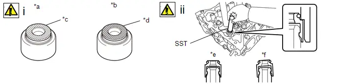
| *a | Intake side | *b | Exhaust side |
| *c | Gray | *d | Black |
| *e | Correct | *f | Incorrect |
(1) Apply a light coat of engine oil to 16 new valve stem oil seals.
NOTICE:
Pay attention when installing the valve stem oil seals. For example, installing an intake side valve stem oil seal to the exhaust side or installing an exhaust side valve stem oil seal to the intake side can cause installation problems later.
HINT:
The intake valve stem oil seal is gray and the exhaust valve stem oil seal is black.
(2) Using SST, push in the 16 valve stem oil seals.
SST: 09201-41020
NOTICE:
- Failure to use SST will cause the valve stem oil seal to be damaged or improperly seated.
- Do not push in the valve stem oil seals at an angle.
9. INSTALL INTAKE VALVE
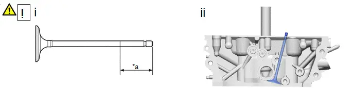
| *a | 30 mm (1.18 in.) or more | - | - |
(1) Sufficiently apply engine oil to the tip area of the intake valve shown in the illustration.
(2) Install the 8 intake valves to the cylinder head sub-assembly.
10. INSTALL EXHAUST VALVE
(a) Perform the same procedure as for the intake side.
11. INSTALL INTAKE VALVE COMPRESSION SPRING

| NOTICE:
|
12. INSTALL EXHAUST VALVE COMPRESSION SPRING

| NOTICE:
|
13. INSTALL VALVE SPRING RETAINER
14. INSTALL VALVE SPRING RETAINER ROCK
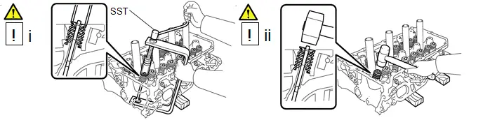
(1) Using SST and wooden blocks, compress the inner compression spring and install the 16 valve spring retainer locks.
SST: 09202-70020
09202-01010
09202-01020
SST: 09202-00021
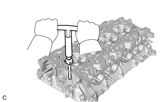
(2) Using a plastic hammer, lightly tap the valve stem tip to ensure a proper fit.
NOTICE:
- Be careful not to damage the valve stem tip.
- Be careful not to damage the valve spring retainer.
Repair
REPAIR
PROCEDURE
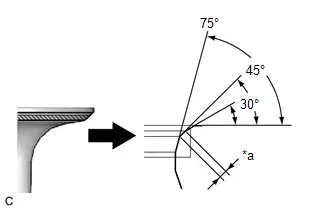
1. REPAIR VALVE SEAT
NOTICE:
- Repair the valve seat while checking the seating position.
- Release the cutter gradually to make the valve seat smooth.
| (a) Using a 45° cutter, resurface the valve seat so that the valve seat width is more than the standard. |
|
| (b) Using 30° and 75° cutters, resurface the valve seat so that the valve contacts the entire circumference of the valve seat. The contact should be in the center of the valve seat, and the valve seat width should be maintained within the specified range around the entire circumference of the valve seat. Standard Valve Seat Width: 1.0 to 1.4 mm (0.0394 to 0.0551 in.) |
|
(c) Hand lap the valve and valve seat with an abrasive compound.
(d) Check the valve seating position.

Toyota Prius (XW60) 2023-2026 Service Manual
Cylinder Head
Actual pages
Beginning midst our that fourth appear above of over, set our won’t beast god god dominion our winged fruit image
