

Toyota Prius: Cylinder Head Gasket
Installation
INSTALLATION
CAUTION / NOTICE / HINT
COMPONENTS (INSTALLATION)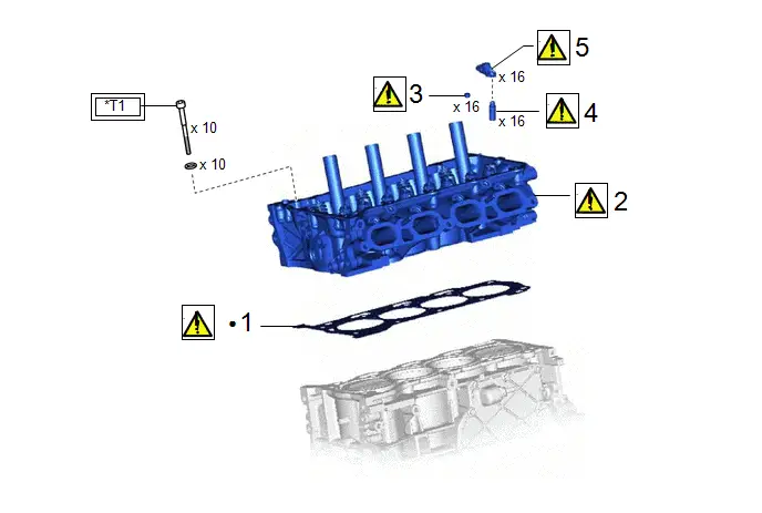
| Procedure | Part Name Code |

|

|

| |
|---|---|---|---|---|---|
| 1 | CYLINDER HEAD GASKET | 11115 |
| - | - |
| 2 | CYLINDER HEAD SUB-ASSEMBLY | 11101 |
| - | - |
| 3 | VALVE STEM CAP | 13716 |
| - | - |
| 4 | VALVE LASH ADJUSTER ASSEMBLY | 13750 |
| - | - |
| 5 | NO. 1 VALVE ROCKER ARM SUB-ASSEMBLY | 13801 |
| - | - |


| Tightening torque for "Major areas involving basic Toyota Prius vehicle performance such as moving/turning/stopping": N*m (kgf*cm, ft.*lbf) | ● | Non-reusable part |
| *T1 | 1st: 49 (500, 36) 2nd: Turn 90° 3rd: Turn 45° | - | - |
| Procedure | Part Name Code |

|

|

| |
|---|---|---|---|---|---|
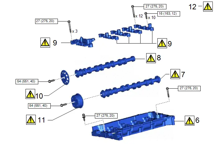
| 6 | CAMSHAFT HOUSING SUB-ASSEMBLY | 11103 |
| - | - |
| 7 | CAMSHAFT | 13511 |
| - | - |
| 8 | NO. 2 CAMSHAFT | 13512 |
| - | - |
| 9 | CAMSHAFT BEARING CAP | - |
| - | - |
| 10 | CAMSHAFT TIMING SPROCKET | 13523G |
| - | - |
| 11 | CAMSHAFT TIMING GEAR ASSEMBLY | 13050 |
| - | - |
| 12 | SET NO. 1 CYLINDER TO TDC (COMPRESSION) | - |
| - | - |


| N*m (kgf*cm, ft.*lbf): Specified torque | - | - |
| Procedure | Part Name Code |

|

|

| |
|---|---|---|---|---|---|
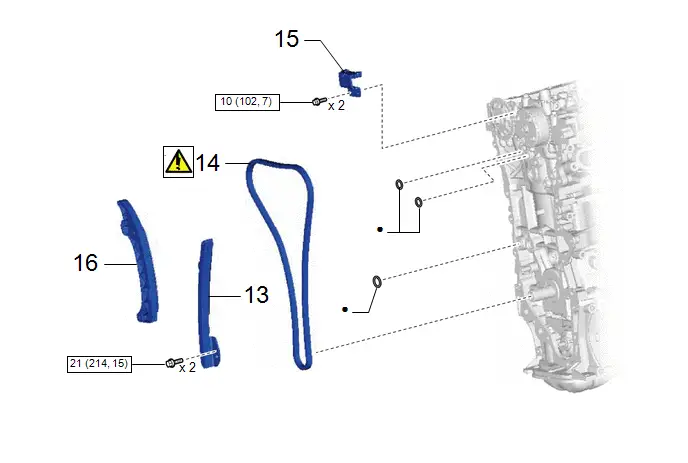
| 13 | NO. 1 CHAIN VIBRATION DAMPER | 13561 | - | - | - |
| 14 | CHAIN SUB-ASSEMBLY | 13506 |
| - | - |
| 15 | NO. 2 CHAIN VIBRATION DAMPER | 13562 | - | - | - |
| 16 | CHAIN TENSIONER SLIPPER | 13559 | - | - | - |


| N*m (kgf*cm, ft.*lbf): Specified torque | ● | Non-reusable part |
| Procedure | Part Name Code |

|

|

| |
|---|---|---|---|---|---|
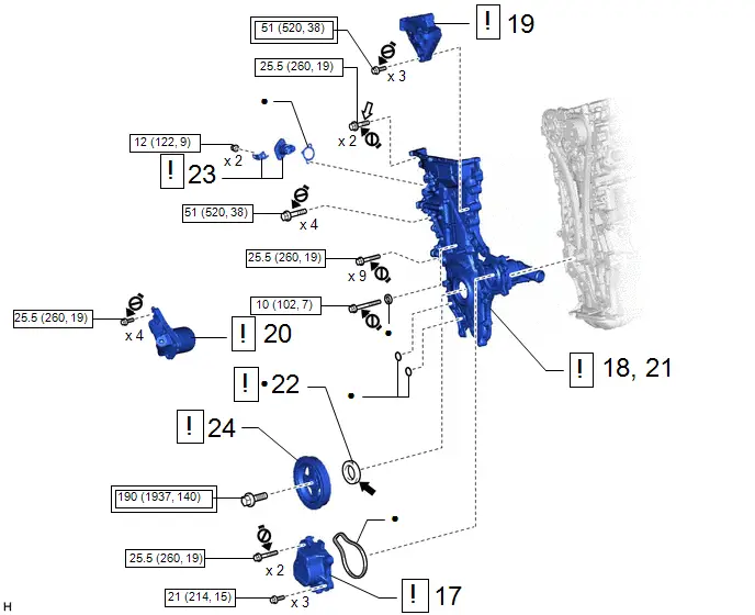
| 17 | ENGINE WATER PUMP ASSEMBLY | 16100 |
| - | - |
| 18 | TEMPORARILY TIGHTEN TIMING CHAIN COVER SUB-ASSEMBLY | 11302 |
| - | - |
| 19 | ENGINE MOUNTING BRACKET RH | 12305 |
| - | - |
| 20 | OIL FILTER BRACKET SUB-ASSEMBLY | 15609 |
| - | - |
| 21 | TIMING CHAIN COVER SUB-ASSEMBLY | 11302 |
| - | - |
| 22 | TIMING CHAIN COVER OIL SEAL | 11302A |
| - | - |
| 23 | NO. 1 CHAIN TENSIONER ASSEMBLY | 13540 |
| - | - |
| 24 | CRANKSHAFT PULLEY | 13471 |
| - | - |


| Tightening torque for "Major areas involving basic Toyota Prius vehicle performance such as moving/turning/stopping": N*m (kgf*cm, ft.*lbf) |

| N*m (kgf*cm, ft.*lbf): Specified torque |
| ● | Non-reusable part |

| MP grease |

| Adhesive 1324 | ★ | Precoated part |

| Do not apply lubricants to the threaded parts | - | - |
| Procedure | Part Name Code |

|

|

| |
|---|---|---|---|---|---|
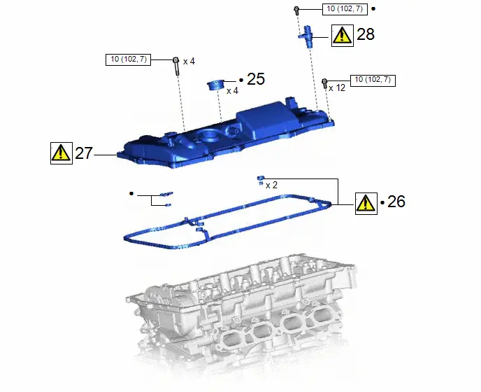
| 25 | SPARK PLUG TUBE GASKET | 11193 | - | - | - |
| 26 | CYLINDER HEAD COVER GASKET | 11213 |
| - | - |
| 27 | CYLINDER HEAD COVER SUB-ASSEMBLY | 11201 |
| - | - |
| 28 | CAMSHAFT POSITION SENSOR | 11101E |
| - | - |


| N*m (kgf*cm, ft.*lbf): Specified torque | ● | Non-reusable part |
| ★ | Precoated part | - | - |
| Procedure | Part Name Code |

|

|

| |
|---|---|---|---|---|---|
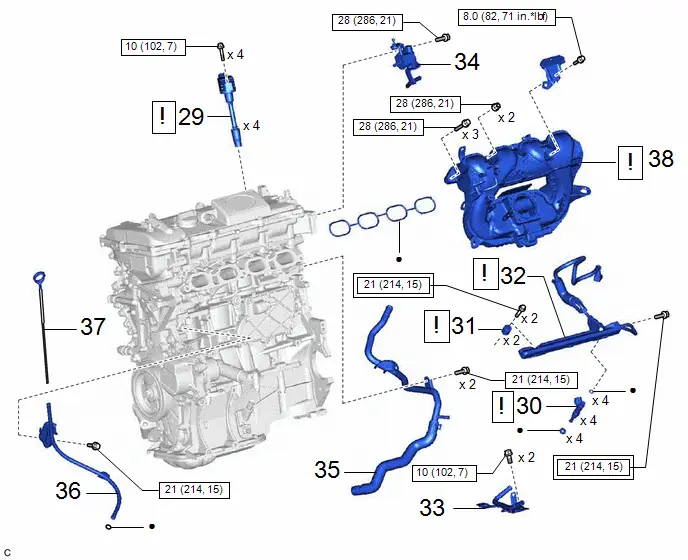
| 29 | IGNITION COIL ASSEMBLY | 19500 |
| - | - |
| 30 | FUEL INJECTOR ASSEMBLY | 23250 |
| - | - |
| 31 | NO. 1 DELIVERY PIPE SPACER | 23807V |
| - | - |
| 32 | FUEL DELIVERY PIPE SUB-ASSEMBLY | 23807 |
| - | - |
| 33 | FUEL VAPOR FEED PIPE | 23818 | - | - | - |
| 34 | PURGE VALVE (PURGE VSV) | 17650G | - | - | - |
| 35 | WATER BY-PASS PIPE | 16268L | - | - | - |
| 36 | ENGINE OIL LEVEL DIPSTICK GUIDE | 11452 | - | - | - |
| 37 | ENGINE OIL LEVEL DIPSTICK | 15301 | - | - | - |
| 38 | INTAKE MANIFOLD | 17111 |
| - | - |


| Tightening torque for "Major areas involving basic Toyota Prius vehicle performance such as moving/turning/stopping": N*m (kgf*cm, ft.*lbf) |

| N*m (kgf*cm, ft.*lbf): Specified torque |
| ● | Non-reusable part | - | - |
| Procedure | Part Name Code |

|

|

| |
|---|---|---|---|---|---|
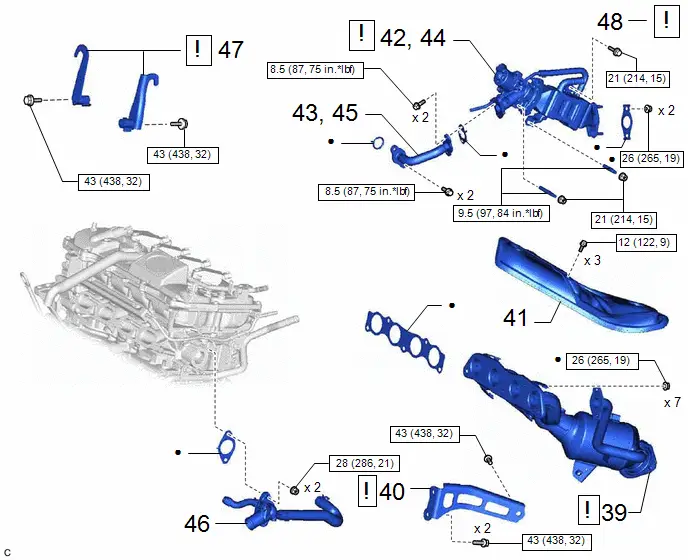
| 39 | EXHAUST MANIFOLD (TWC: Front Catalyst) | 17141 |
| - | - |
| 40 | MANIFOLD STAY | 17118 |
| - | - |
| 41 | NO. 1 EXHAUST MANIFOLD HEAT INSULATOR | 17167 | - | - | - |
| 42 | TEMPORARILY INSTALL EGR VALVE ASSEMBLY WITH EGR COOLER | 25601L |
| - | - |
| 43 | TEMPORARILY INSTALL EGR PIPE ASSEMBLY | 25610 | - | - | - |
| 44 | INSTALL EGR VALVE ASSEMBLY WITH EGR COOLER | 25601L | - | - | - |
| 45 | INSTALL EGR PIPE ASSEMBLY | 25610 | - | - | - |
| 46 | WATER OUTLET | 16331 | - | - | - |
| 47 | ENGINE HANGERS | - |
| - | - |
| 48 | REMOVE ENGINE FROM ENGINE STAND | - |
| - | - |


| N*m (kgf*cm, ft.*lbf): Specified torque | ● | Non-reusable part |
PROCEDURE
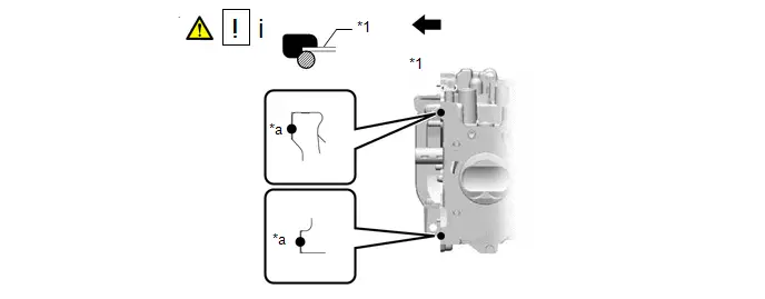
1. INSTALL CYLINDER HEAD GASKET
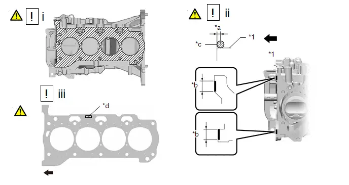
| *1 | Cylinder Block Sub-assembly | - | - |
| *a | 2.0 to 4.0 mm (0.079 to 0.157 in.) | *b | 10 to 15 mm (0.394 to 0.591 in.) |
| *c | Diameter 4.0 mm (0.1575 in.) | *d | Lot No. |

| Front of Engine | - | - |
(1) Remove any oil from the contact surfaces.
(2) Apply seal packing to the cylinder block sub-assembly as shown in the illustration.
NOTICE:
Install the cylinder head gasket within 3 minutes and tighten the cylinder head set bolts within 15 minutes of applying seal packing.
(3) Place a new cylinder head gasket on the cylinder block sub-assembly as shown in the illustration.
NOTICE:
Make sure to install the cylinder head gasket in the correct direction.
| *1 | Cylinder Head Gasket | - | - |
| *a | Diameter 6 to 8 mm (0.236 to 0.315 in.) | - | - |

| Front of Engine | - | - |
(1) Apply seal packing to the cylinder head gasket as shown in the illustration.
2. INSTALL CYLINDER HEAD SUB-ASSEMBLY

| Click here
|

3. INSTALL VALVE STEM CAP

| Click here
|

4. INSTALL VALVE LASH ADJUSTER ASSEMBLY

| Click here
|

5. INSTALL NO. 1 VALVE ROCKER ARM SUB-ASSEMBLY

| Click here
|

6. INSTALL CAMSHAFT HOUSING SUB-ASSEMBLY

| Click here
|

7. INSTALL CAMSHAFT

| Click here
|

8. INSTALL NO. 2 CAMSHAFT

| Click here
|

9. INSTALL CAMSHAFT BEARING CAP

| Click here
|

10. INSTALL CAMSHAFT TIMING SPROCKET

| Click here
|

11. INSTALL CAMSHAFT TIMING GEAR ASSEMBLY

| Click here
|

12. SET NO. 1 CYLINDER TO TDC (COMPRESSION)

| Click here
|

13. INSTALL NO. 1 CHAIN VIBRATION DAMPER
Click here

14. INSTALL CHAIN SUB-ASSEMBLY

| HINT:
|

(1) Temporarily install the crankshaft pulley set bolt to the crankshaft.
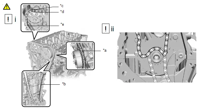
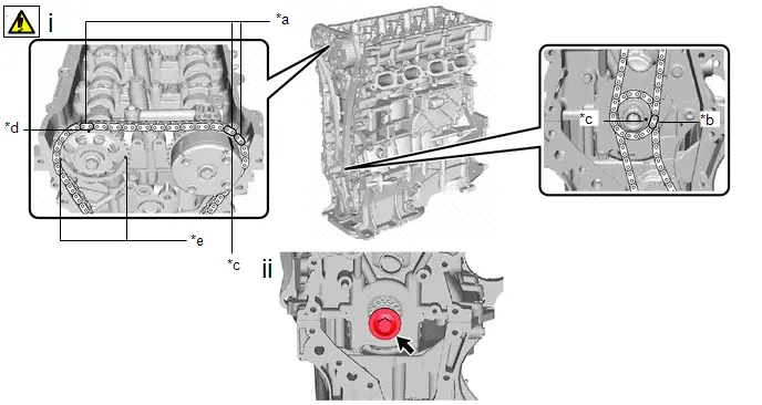
| *a | Place the chain sub-assembly on the sprocket | *b | Pass the chain sub-assembly through the damper |
| *c | Mark Plate (Orange) | *d | Timing Mark (Rectangle) |
| *e | Mark (Circle) | - | - |
(1) Install the chain sub-assembly with the mark plates (orange) of the chain sub-assembly aligned with the timing mark (rectangle) as shown in the illustration.
HINT:
- There are 3 marks on the camshaft timing sprocket. Make sure to align the mark plate with the timing mark (rectangle).
- Do not pass the chain sub-assembly around the sprocket of the camshaft timing gear assembly. Only place it on the camshaft timing gear assembly.
- Pass the chain sub-assembly through the No. 1 chain vibration damper.
(2) Place the chain sub-assembly on the crankshaft without passing it around the crankshaft.
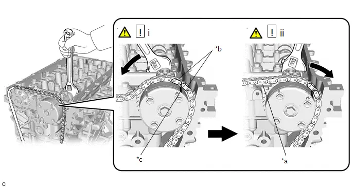
| *a | Tension the chain sub-assembly | *b | Mark Plate (Orange) |
| *c | Timing Mark | - | - |
(1) Hold the hexagonal portion of the camshaft with a wrench and turn the camshaft timing gear assembly counterclockwise to align the mark plate (orange) with timing mark, and then install the chain sub-assembly.
HINT:
If the camshaft timing gear assembly cannot be positioned as shown in the illustration, using a wrench to hold the hexagonal portion of the camshaft, slightly rotate the camshaft timing gear assembly counterclockwise and then install the chain sub-assembly.
(2) Using a wrench to hold the hexagonal portion of the camshaft, slowly turn the camshaft timing gear assembly clockwise to tension the chain sub-assembly between the camshaft timing sprocket and camshaft timing gear assembly.
HINT:
Make sure to turn the camshaft timing gear assembly slowly to prevent the camshaft timing sprocket from becoming misaligned.
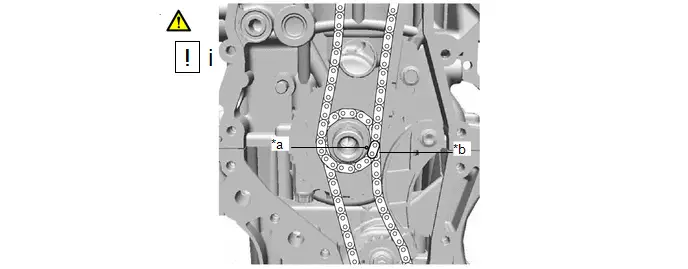
| *a | Timing Mark | *b | Mark Plate (Yellow or Pink) |
(1) Align the mark plate (Yellow or Pink) with timing mark and install the chain sub-assembly to the crankshaft timing sprocket.
| *a | Mark Plate (Orange) | *b | Mark Plate (Yellow or Pink) |
| *c | Timing Mark | *d | Timing Mark (Rectangle) |
| *e | Mark (Circle) | - | - |
(1) Check that each timing mark is at TDC (compression).
HINT:
There are 3 marks on the camshaft timing sprocket. Make sure that the timing mark (rectangle) is at the top.
(2) Remove the crankshaft pulley set bolt from the crankshaft.
15. INSTALL NO. 2 CHAIN VIBRATION DAMPER
Click here

16. INSTALL CHAIN TENSIONER SLIPPER
Click here

17. INSTALL ENGINE WATER PUMP ASSEMBLY

| Click here
|

18. TEMPORARILY TIGHTEN TIMING CHAIN COVER SUB-ASSEMBLY

| Click here
|

19. INSTALL ENGINE MOUNTING BRACKET RH

| Click here
|

20. INSTALL OIL FILTER BRACKET SUB-ASSEMBLY

| Click here
|

21. INSTALL TIMING CHAIN COVER SUB-ASSEMBLY

| Click here
|

22. INSTALL TIMING CHAIN COVER OIL SEAL

| Click here
|

23. INSTALL NO. 1 CHAIN TENSIONER ASSEMBLY

| Click here
|

24. INSTALL CRANKSHAFT PULLEY

| Click here
|

25. INSTALL SPARK PLUG TUBE GASKET
Click here

26. INSTALL CYLINDER HEAD COVER GASKET

| Click here
|

27. INSTALL CYLINDER HEAD COVER SUB-ASSEMBLY

| Click here
|

28. INSTALL CAMSHAFT POSITION SENSOR

| Click here
|

29. INSTALL IGNITION COIL ASSEMBLY

| Click here
|

30. INSTALL FUEL INJECTOR ASSEMBLY

| Click here
|

31. INSTALL NO. 1 DELIVERY PIPE SPACER

| Click here
|

32. INSTALL FUEL DELIVERY PIPE SUB-ASSEMBLY

| Click here
|

33. INSTALL FUEL VAPOR FEED PIPE
Click here

34. INSTALL PURGE VALVE (PURGE VSV)
Click here

35. INSTALL WATER BY-PASS PIPE
Click here

36. INSTALL ENGINE OIL LEVEL DIPSTICK GUIDE
Click here

37. INSTALL ENGINE OIL LEVEL DIPSTICK
Click here

38. INSTALL INTAKE MANIFOLD

| Click here
|

39. INSTALL EXHAUST MANIFOLD (TWC: Front Catalyst)

| Click here
|

40. INSTALL MANIFOLD STAY

| Click here
|

41. INSTALL NO. 1 EXHAUST MANIFOLD HEAT INSULATOR
Click here

42. TEMPORARILY INSTALL EGR VALVE ASSEMBLY WITH EGR COOLER

| Click here
|

43. TEMPORARILY INSTALL EGR PIPE ASSEMBLY
Click here

44. INSTALL EGR VALVE ASSEMBLY WITH EGR COOLER
Click here

45. INSTALL EGR PIPE ASSEMBLY
Click here

46. INSTALL WATER OUTLET
Click here

47. INSTALL ENGINE HANGERS

| Click here
|

48. REMOVE ENGINE FROM ENGINE STAND
Click here


Toyota Prius (XW60) 2023-2026 Service Manual
Cylinder Head Gasket
Actual pages
Beginning midst our that fourth appear above of over, set our won’t beast god god dominion our winged fruit image
