

Toyota Prius: Cylinder Block
Precaution
PRECAUTION
HINT:
- Any digits beyond the 0.01 mm (1/1000 in.) place for standard, minimum and maximum values should be used as a reference only.
- When both standard and maximum or minimum values are listed for an inspection, use the standard value as a reference only and base any judgments on the maximum and minimum values.
Disassembly
DISASSEMBLY
CAUTION / NOTICE / HINT
The necessary procedures (adjustment, calibration, initialization or registration) that must be performed after parts are removed and installed, or replaced during engine unit removal/installation are shown below.
Necessary Procedures After Parts Removed/Installed/Replaced| Replaced Part or Performed Procedure | Necessary Procedure | Effect/Inoperative Function when Necessary Procedure not Performed | Link |
|---|---|---|---|
|
*: Even when not replacing the part, it is necessary to perform the specified necessary procedures after installation.
*1: Also necessary after performing a tire rotation. *2: It is not necessary to perform this procedure if the tire pressure warning valve and transmitters are installed to the same location. | |||
| Replacement of ECM | Update ECU security key | Toyota Prius Vehicle Control History (RoB) are stored |
|
| ECU configuration | - |
| |
| Perform Toyota Prius Vehicle Identification Number (VIN) registration | DTC is output |
| |
| Inspection after repair |
|
|
| Replacement of inverter with converter assembly | ECU configuration | - |
|
| Resolver learning |
|
| |
| Replacement of hybrid vehicle transaxle assembly |
|
|
|
| Suspension parts | Rear television camera assembly optical axis (Back camera position setting) | Parking Assist Monitor System |
|
| Parking assist ECU initialization | Panoramic View Monitor System |
| |
| Advanced Park |
| ||
| Tires |
| Tire Pressure Warning System | Refer to Procedures Necessary When Replacing Parts (for Tire Pressure Warning System) table below |
| Rear television camera assembly optical axis (Back camera position setting) | Parking Assist Monitor System |
| |
| Parking assist ECU initialization | Panoramic View Monitor System |
| |
| Advanced Park |
| ||
| Replacement of front bumper assembly* | Front television camera view adjustment | Panoramic View Monitor System |
|
| Advanced Park |
| ||


HINT:
When the cable is disconnected / reconnected to the auxiliary battery terminal, systems temporarily stop operating. However, each system has a function that completes learning the first time the system is used.
-
Learning completes when Toyota Prius vehicle is driven
Effect/Inoperative Function When Necessary Procedures are not Performed
Necessary Procedures
Link
Front Camera System
Drive the Toyota Prius vehicle straight ahead at 35 km/h (22 mph) or more for 5 seconds or more.

-
Learning completes when vehicle is operated normally
Effect/Inoperative Function When Necessary Procedures are not Performed
Necessary Procedures
Link
*1: w/o Power Back Door System *2: w/ Power Back Door System
Power Door Lock Control System*1
- Back door opener
Perform door unlock operation with door control switch or electrical key transmitter sub-assembly switch.

Power Back Door System*2
Reset back door close position

Air Conditioning System
After the ignition switch is turned to ON, the servo motor standard position is recognized.
-
CAUTION / NOTICE / HINT
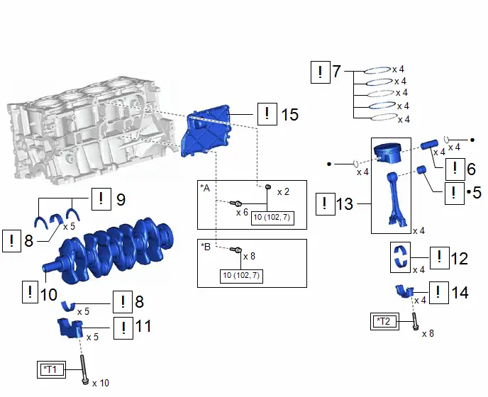
COMPONENTS (DESASSEMBLY)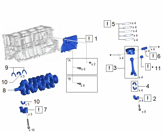
| Procedure | Part Name Code |

|

|

| |
|---|---|---|---|---|---|
| 1 | NO. 1 VENTILATION CASE | 12211 |
| - | - |
| 2 | CONNECTING ROD CAP | - |
| - | - |
| 3 | PISTON SUB-ASSEMBLY WITH CONNECTING ROD | - |
| - | - |
| 4 | CONNECTING ROD BEARING | 13041 | - | - | - |
| 5 | PISTON RING SET | 13011 |
| - | - |
| 6 | PISTON PIN | - |
| - | - |
| 7 | CRANKSHAFT BEARING CAP | - |
| - | - |
| 8 | CRANKSHAFT | 13411 | - | - | - |
| 9 | UPPER CRANKSHAFT THRUST WASHER | 11791 | - | - | - |
| 10 | CRANKSHAFT BEARING | 11711 | - | - | - |
| 11 | CONNECTING ROD SMALL END BUSH | 13201A |
| - | - |


| *A | Type A | *B | Type B |
| ● | Non-reusable part | - | - |
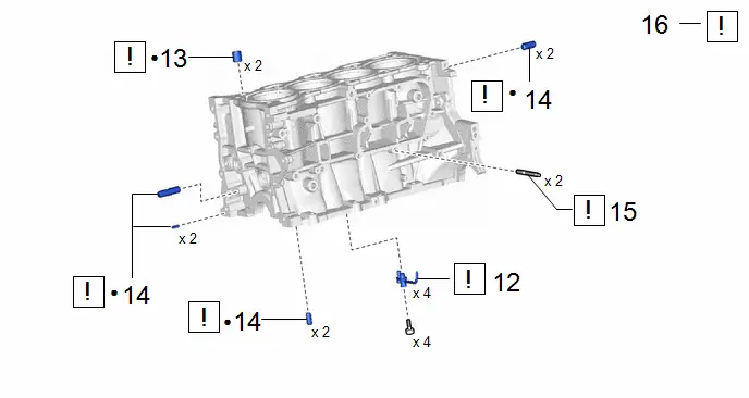
| Procedure | Part Name Code |

|

|

| |
|---|---|---|---|---|---|
| 12 | NO. 1 OIL NOZZLE SUB-ASSEMBLY | 15708 |
| - | - |
| 13 | RING PIN | - |
| - | - |
| 14 | STRAIGHT PIN | - |
| - | - |
| 15 | STUD BOLT | - |
| - | - |
| 16 | CLEAN CYLINDER BLOCK | - |
| - | - |


| ● | Non-reusable part | - | - |
PROCEDURE
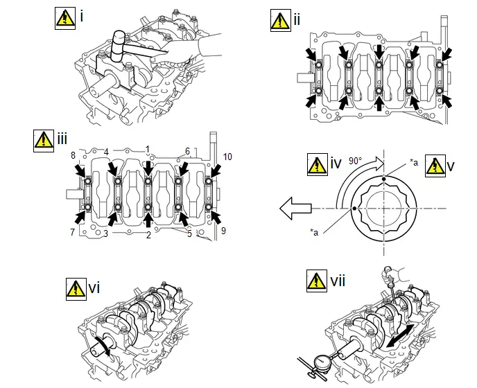
1. REMOVE NO. 1 VENTILATION CASE
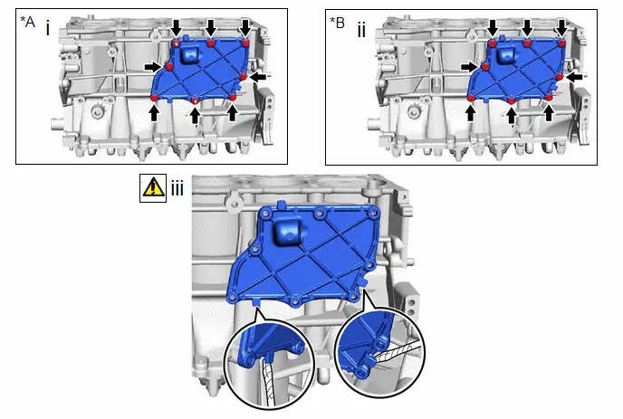
| *A | Type A | *B | Type B |
(1) Type A:
Remove the 6 bolts and 2 nuts.
(2) Type B:
Remove the 8 bolts.
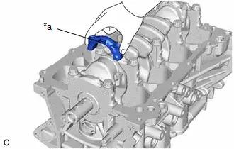
(3) Remove the No. 1 ventilation case by prying between the No. 1 ventilation case and cylinder block sub-assembly with a screwdriver with its tip wrapped with protective tape.
NOTICE:
Be careful not to damage the contact surfaces of the cylinder block sub-assembly and No. 1 ventilation case.
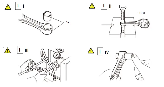
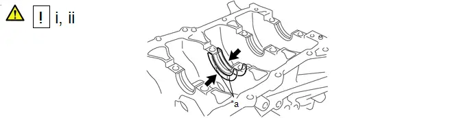
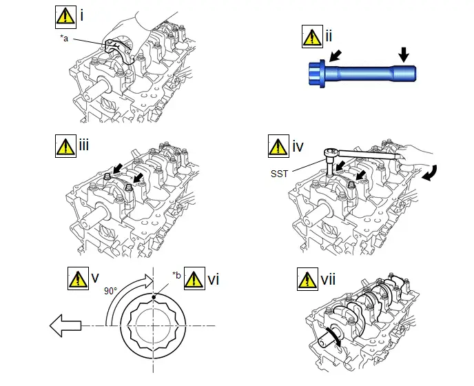
2. REMOVE CONNECTING ROD CAP
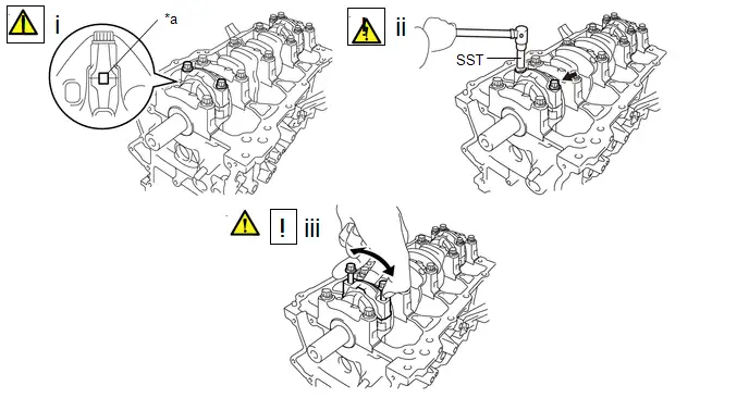
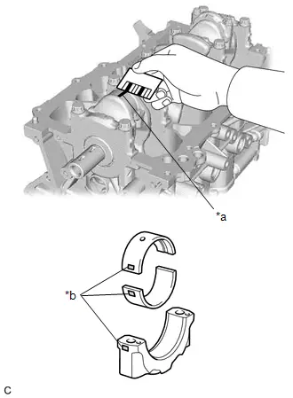
| *a | Paint Mark | - | - |
(1) Place a paint mark across each corresponding connecting rod and connecting rod cap.
HINT:
The paint marks are used to ensure that the same parts are installed in the same combination to their original locations.
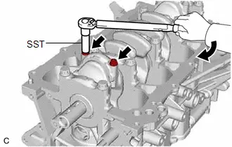
(2) Using SST, remove the 8 connecting rod bolts from the connecting rod caps.
SST: 09205-16011
(3) Using the 2 removed connecting rod bolts, remove the 4 connecting rod caps with connecting rod bearings by wiggling each connecting rod cap left and right.
HINT:
Keep the connecting rod bearing installed to the connecting rod cap.
3. REMOVE PISTON SUB-ASSEMBLY WITH CONNECTING ROD
(1) Using a ridge reamer, scrape off any carbon on the top of the cylinder.
(2) Push out the 4 pistons with 4 connecting rods and 4 connecting rod bearings through the top of the cylinder block sub-assembly.
HINT:
- Keep the connecting rod bearings, connecting rods and connecting rod caps together.
- Arrange the removed parts in such a way that they can be reinstalled to their original locations.
4. REMOVE CONNECTING ROD BEARING
5. REMOVE PISTON RING SET
(1) Using a piston ring expander, remove the No. 1 compression ring and No. 2 compression ring from the piston.
(2) Remove the oil ring expander, upper side rail and lower side rail from the piston by hand.
HINT:
Arrange the removed parts in such a way that they can be reinstalled to their original locations.
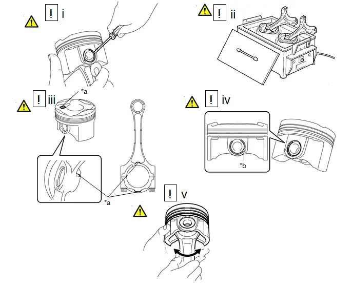
6. REMOVE PISTON PIN
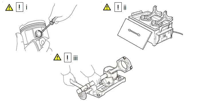
(1) Using a screwdriver, pry out the piston pin hole snap ring from the piston.
NOTICE:
- Do not remove the piston pin hole snap ring (rear side) unless it is being replaced.
- Be careful not to damage the piston when removing the piston pin hole snap ring (rear side).
(2) Gradually heat each piston to approximately 80 to 90°C (176 to 194°F).
CAUTION:
Be sure to wear protective gloves.
(3) Using a plastic hammer and brass bar, lightly tap out the piston pin and remove the connecting rod.
HINT:
- The piston and piston pin are a matched set.
- Arrange the pistons, piston pins, piston rings, connecting rods and connecting rod bearings in the correct order.
7. REMOVE CRANKSHAFT BEARING CAP
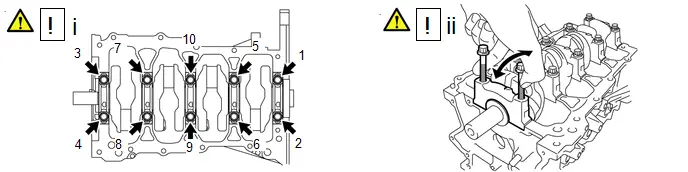
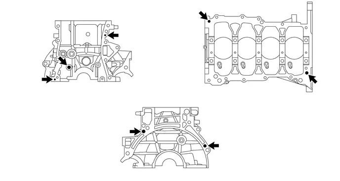
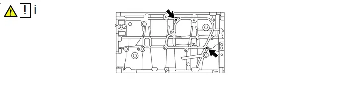
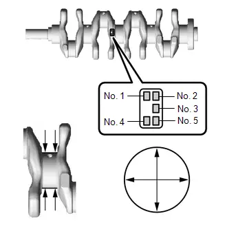
(1) Uniformly loosen and remove the 10 crankshaft bearing cap set bolts in several steps in the order shown in the illustration.
(2) Using the 2 removed crankshaft bearing cap set bolts, remove the 5 crankshaft bearing caps from the cylinder block sub-assembly by wiggling each crankshaft bearing cap back and forth.
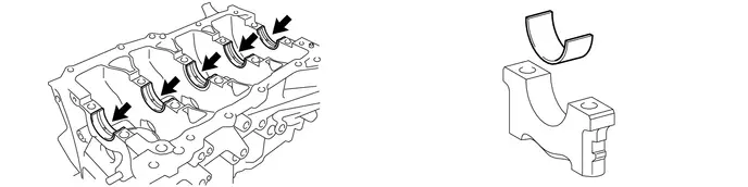
8. REMOVE CRANKSHAFT

9. REMOVE UPPER CRANKSHAFT THRUST WASHER

10. REMOVE CRANKSHAFT BEARING
11. REMOVE CONNECTING ROD SMALL END BUSH
(1) Using SST and a press, press out the connecting rod small end bush.
SST: 09222-30010
12. REMOVE NO. 1 OIL NOZZLE SUB-ASSEMBLY
(1) Using a 5 mm hexagon socket wrench, remove the 4 bolts and 4 No. 1 oil nozzle sub-assemblies from the cylinder block sub-assembly.
13. REMOVE RING PIN

| NOTICE: It is not necessary to remove the ring pins unless they are being replaced. |

14. REMOVE STRAIGHT PIN

| NOTICE: It is not necessary to remove the straight pins unless they are being replaced. |
15. REMOVE STUD BOLT

| NOTICE: If a stud bolt is deformed or its threads are damaged, replace it. |
(1) Using an E6 "TORX" socket wrench, remove the 2 stud bolts from the cylinder block sub-assembly.
16. CLEAN CYLINDER BLOCK

| NOTICE: If the cylinder is washed at high temperature, the cylinder liner will stick out beyond the cylinder block. Always wash the cylinder block at a temperature of 45°C (113°F) or less. |
Inspection
INSPECTION
PROCEDURE
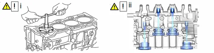
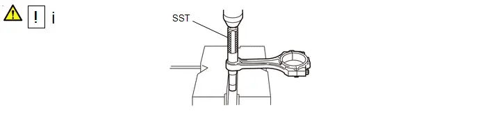
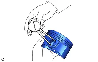
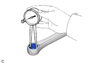
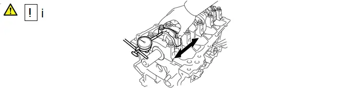
1. INSPECT CONNECTING ROD THRUST CLEARANCE
| (a) Using a dial indicator, measure the thrust clearance while moving the connecting rod back and forth. Standard Thrust Clearance:
|
|
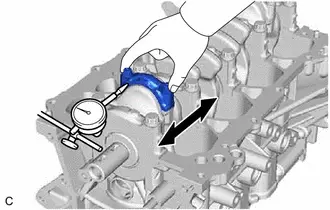
(b) If the thrust clearance is more than the maximum, replace the connecting rod. If necessary, replace the crankshaft.
2. INSPECT CONNECTING ROD OIL CLEARANCE
HINT:
Using SST, install and alternately tighten the 2 connecting rod bolts in several steps.
Pre-procedure1
(a) Remove the connecting rod cap.
HINT:
Click here

(b) Remove the connecting rod bearing.
HINT:
Click here

(c) Clean the crankshaft crank pin and connecting rod bearing.
(d) Check the crankshaft crank pin and connecting rod bearing for pitting and scratches.
(e) If the crank pin or upper connecting rod bearing is damaged, replace the connecting rod bearings. If necessary, replace the crankshaft.
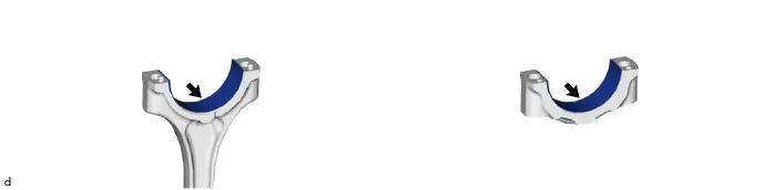
| (f) Lay a strip of Plastigage on the crank pin. |
|
| (g) Check that the front mark of the connecting rod cap is facing the correct direction, and install the connecting rod bearing cap to the connecting rod. |
|
(h) Apply a light coat of engine oil to the threads and under the heads of the 2 connecting rod bolts.
| (i) Using SST, install and alternately tighten the 2 connecting rod bolts in several steps. SST: 09205-16011 Torque: 20 N·m {204 kgf·cm, 15 ft·lbf} |
|
(j) Mark the front of each connecting rod bolt with paint.
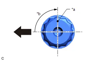
| *a | Paint Mark |
| *b | 90° |

| Front of Engine |
(k) Tighten the connecting rod bolts 90° as shown in the illustration.
NOTICE:
Do not turn the crankshaft during the measurement.
(l) Remove the 2 connecting rod bolts and connecting rod bearing cap.
Procedure1
| (m) Measure the Plastigage at its widest point. Standard Oil Clearance:
HINT: If replacing a connecting rod bearing, select a new one with the same number as marked on the connecting rod cap. There are 3 sizes of standard connecting rod bearings, marked "1", "2", or "3" accordingly. Standard Connecting Rod Large End Bore Diameter:
Standard Connecting Rod Bearing Thickness:
Standard Crankshaft Pin Diameter:
NOTICE: Completely remove the Plastigage after the measurement. |
|
(n) If the oil clearance is more than the maximum, replace the connecting rod bearings. If necessary, replace the crankshaft.
Post-procedure1
(o) None
3. INSPECT CRANKSHAFT THRUST CLEARANCE
| (a) Using a dial indicator, measure the crankshaft thrust clearance while prying the crankshaft back and forth with a screwdriver. Standard Thrust Clearance:
Standard Thrust Washer Thickness:
|
|
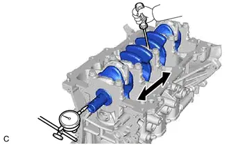
(b) If the thrust clearance is more than the maximum, replace the crankshaft thrust washer set. If necessary, replace the crankshaft.
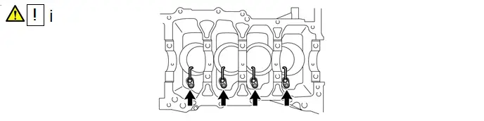
4. INSPECT CRANKSHAFT OIL CLEARANCE
Pre-procedure1
(a) Check the crankshaft journals and crankshaft bearings for pitting and scratches.
(b) Install the crankshaft bearings.
HINT:
Click here

(c) Install the upper crankshaft thrust washers.
HINT:
Click here

(d) Clean each main journal and crankshaft bearing.
(e) Place the crankshaft on the cylinder block sub-assembly.
| (f) Lay a strip of Plastigage across each journal. |
|
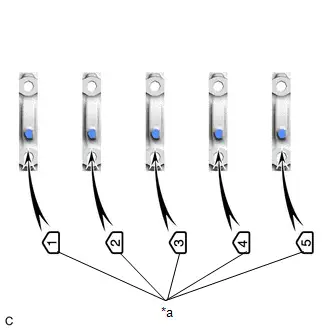
| (g) Confirm the front marks and numbers, and place the 5 crankshaft bearing caps on the cylinder block sub-assembly. HINT: A number is marked on each crankshaft bearing cap to indicate the installation position. |
|
(h) Install the crankshaft bearing caps.
NOTICE:
Do not turn the crankshaft.
HINT:
Click here

(i) Remove the crankshaft bearing caps.
HINT:
Click here

Procedure1
(j) Measure the Plastigage at its widest point.
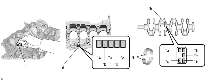
| *a | No. 1 | *b | No. 2 |
| *c | No. 3 | *d | No. 4 |
| *e | No. 5 | *f | Plastigage |
| *g | Cylinder Block Number Mark | *h | Crankshaft Number Mark |
| *i | Diameter Mark | - | - |
Standard Oil Clearance:
| Maximum Warpage | Specified Condition | Result |
|---|---|---|
| 0.05 mm 0.00197 in. | 0.014 to 0.038 mm 0.00055 to 0.00150 in. | mm in. |
NOTICE:
Completely remove the Plastigage after the measurement.
(k) If replacing a crankshaft bearing, select a new one with the same number.
HINT:
- If the number of the crankshaft bearing cannot be determined, select the correct crankshaft bearing number by adding together the numbers imprinted on the cylinder block sub-assembly and crankshaft. Then refer to the following table for the appropriate crankshaft bearing number. There are 4 sizes of standard crankshaft bearings, marked "1", "2", "3" or "4" accordingly.
- Example: Cylinder block "4" Crankshaft "3" = Total number 7 (Use crankshaft bearing "3")
Crankshaft Bearing:
| Cylinder block sub-assembly Crankshaft | Crankshaft bearing to be used |
|---|---|
| 0 to 2 | "1" |
| 3 to 5 | "2" |
| 6 to 8 | "3" |
| 9 to 11 | "4" |
Standard Cylinder Block Journal Bore Diameter:
| Mark | Specified Condition |
|---|---|
| 0 | 52.000 to 52.002 mm (2.04724 to 2.04732 in.) |
| 1 | 52.003 to 52.004 mm (2.04736 to 2.04740 in.) |
| 2 | 52.005 to 52.006 mm (2.04744 to 2.04748 in.) |
| 3 | 52.007 to 52.009 mm (2.04752 to 2.04759 in.) |
| 4 | 52.010 to 52.011 mm (2.04763 to 2.04767 in.) |
| 5 | 52.012 to 52.013 mm (2.04771 to 2.04775 in.) |
| 6 | 52.014 to 52.016 mm (2.04779 to 2.04787 in.) |
Standard Crankshaft Journal Diameter:
| Mark | Specified Condition |
|---|---|
| 0 | 47.999 to 48.000 mm (1.88972 to 1.88976 in.) |
| 1 | 47.997 to 47.998 mm (1.88964 to 1.88968 in.) |
| 2 | 47.995 to 47.996 mm (1.88956 to 1.88960 in.) |
| 3 | 47.993 to 47.994 mm (1.88948 to 1.88952 in.) |
| 4 | 47.991 to 47.992 mm (1.88941 to 1.88945 in.) |
| 5 | 47.988 to 47.990 mm (1.88929 to 1.88937 in.) |
Standard Bearing Center Wall Thickness:
| Mark | Specified Condition |
|---|---|
| 1 | 1.991 to 1.994 mm (0.07839 to 0.07850 in.) |
| 2 | 1.995 to 1.997 mm (0.07854 to 0.07862 in.) |
| 3 | 1.998 to 2.000 mm (0.07866 to 0.07874 in.) |
| 4 | 2.001 to 2.003 mm (0.07878 to 0.07886 in.) |
Post-procedure1
(l) None
5. INSPECT CYLINDER BLOCK FOR WARPAGE
| (a) Using a precision straightedge and feeler gauge, check the surfaces which contact the cylinder head gasket for warpage. Maximum Warpage:
|
|
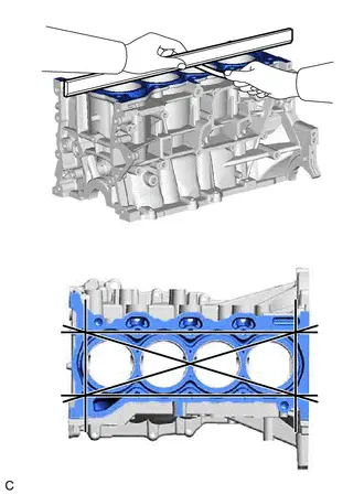
(b) If the warpage is more than the maximum, replace the cylinder block sub-assembly.
6. INSPECT CYLINDER BORE
(a) Using a cylinder gauge, measure the cylinder bore diameter at the positions (A) and (B) in the thrust and axial directions.
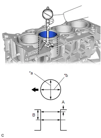
| *a | Thrust Direction |
| *b | Axial Direction |

| Front of Engine |
Reference Diameter (New Parts):
| Maximum Diameter | Specified Condition | Result |
|---|---|---|
| 80.63 mm 3.17 in. | 80.500 to 80.513 mm 3.16929 to 3.16980 in. | mm in. |
Measurement Position:
| Measurement Position | Cylinder Bore Position |
|---|---|
| (A) | 10 mm (0.394 in.) from top edge |
| (B) | 50 mm (1.97 in.) from top edge |
(b) If the average diameter of 4 positions is more than the maximum, replace the cylinder block sub-assembly.
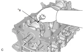
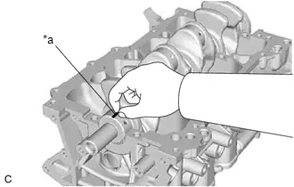
7. INSPECT NO. 1 OIL NOZZLE SUB-ASSEMBLY
| (a) Push the check valve with a pin to check that it is not stuck. |
|
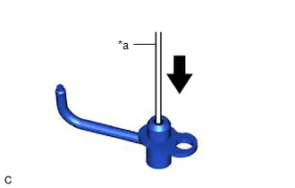
(b) If the check valve is stuck, replace the No. 1 oil nozzle sub-assembly.
| (c) Apply air into (A). Check that air does not leak through (B). |
|
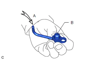
(d) If air leaks, clean or replace the No. 1 oil nozzle sub-assembly.
| (e) Push the check valve with a pin while applying air into (A). Check that air passes through (B). |
|
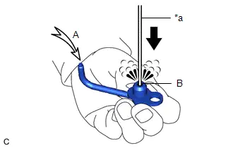
(f) If air does not pass through (B), clean or replace the No. 1 oil nozzle sub-assembly.
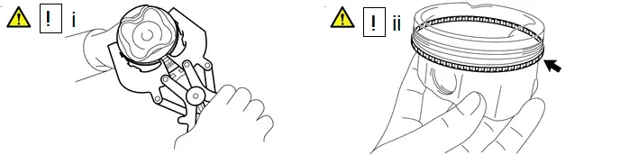
8. INSPECT PISTON SUB-ASSEMBLY WITH CONNECTING ROD
| (a) Check the fitting condition between the piston and piston pin by trying to move the piston back and forth on the piston pin. |
|
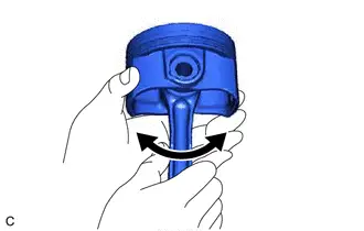
(b) If abnormal movement is felt, replace the piston and piston pin as a set.
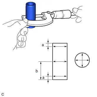
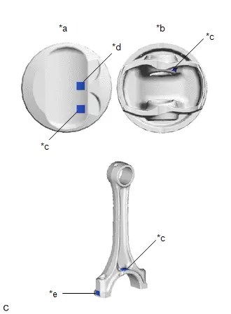
9. INSPECT PISTON
| (a) Using a micrometer, measure the piston diameter at a position 9.0 mm (0.354 in.) from the bottom of the piston (refer to the illustration). Reference Piston Diameter (New Parts):
|
|
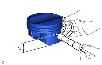
(b) If the piston diameter is less than the minimum, replace the piston and piston pin as a set.
10. INSPECT PISTON OIL CLEARANCE
(a) Subtract the piston diameter measurement from the cylinder bore diameter measurement.
Reference Oil Clearance (New Parts):
| Maximum Oil Clearance | Specified Condition | Result |
|---|---|---|
| 0.08 mm 0.00315 in. | -0.003 to 0.040 mm -0.000118 to 0.00157 in. | mm in. |
(b) If the piston oil clearance is more than the maximum, replace all the pistons with piston pins. If necessary, replace the cylinder block sub-assembly.
11. INSPECT RING GROOVE CLEARANCE
| (a) Using a feeler gauge, measure the clearance between a new piston ring set and the wall of the ring groove. Standard Ring Groove Clearance:
|
|
(b) If the groove clearance is not as specified, replace the piston and piston pin as a set.
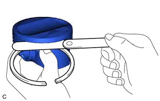
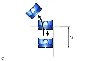
12. INSPECT PISTON RING END GAP
Pre-procedure1
| (a) Using a piston, push the piston ring a little beyond the bottom of the ring travel, 50 mm (1.97 in.) from the top of the cylinder block sub-assembly. |
|
Procedure1
| (b) Using a feeler gauge, measure the end gap. Standard End Gap:
|
|
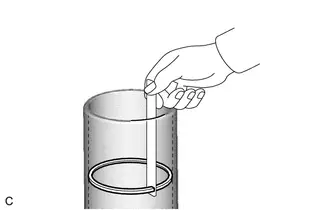
(c) If the end gap is more than the maximum, replace the piston ring. If the end gap is more than the maximum even with a new piston ring, replace the cylinder block sub-assembly.
Post-procedure1
(d) None
13. INSPECT PISTON PIN OIL CLEARANCE
HINT:
When replacing the piston and piston pin with supply parts, there are a number of piston diameter sizes to choose from, but there is only one size of piston pin diameter.
| (a) Using a caliper gauge, measure the piston pin bore diameter. Standard Piston Pin Bore Diameter: 20.006 to 20.015 mm (0.78764 to 0.78799 in.)
|
|
(b) If the diameter is not as specified, replace the piston and piston pin as a set.
| (c) Using a micrometer, measure the piston pin diameter. Standard Piston Pin Diameter: 20.004 to 20.013 mm (0.78756 to 0.78791 in.)
Measurement Position:
|
|
(d) If the diameter is not as specified, replace the piston and piston pin as a set.
| (e) Using a caliper gauge, measure the connecting rod small end bush bore diameter. Standard Connecting Rod Small End Bush Bore Diameter: 20.012 to 20.021 mm (0.78787 to 0.78823 in.)
|
|
(f) If the diameter is not as specified, replace the connecting rod small end bush.
| (g) Subtract the piston pin diameter measurement from the piston pin bore diameter measurement. Standard Oil Clearance:
|
|
(h) If the oil clearance is more than the maximum, replace the piston and piston pin as a set.
(i) Subtract the piston pin diameter measurement from the bushing inside diameter measurement.
Standard Oil Clearance:
| Maximum Oil Clearance | Specified Condition | Result |
|---|---|---|
| 0.014 mm 0.000551 in. | 0.005 to 0.011 mm 0.000197 to 0.000433 in. | mm in. |
(j) If the oil clearance is more than the maximum, replace the connecting rod small end bush. If necessary, replace the piston and piston pin as a set.
14. INSPECT CONNECTING ROD BOLT
| (a) Using a vernier caliper, measure the diameter of the connecting rod bolt at several points within the area shown in the illustration. Standard Diameter:
NOTICE:
|
|
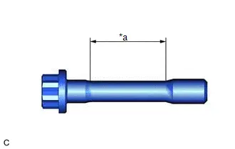
(b) If the diameter is less than the minimum, replace the connecting rod bolt.
15. INSPECT CRANKSHAFT
(a) Inspect the runout.
| (1) Using a dial indicator and V-blocks, measure the runout as shown in the illustration. Maximum Runout:
|
|
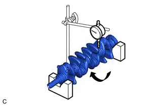
(2) If the runout is more than the maximum, replace the crankshaft.
(b) Inspect the main journals.
| (1) Using a micrometer, measure the diameter of each main journal. Standard Diameter: 47.988 to 48.000 mm (1.88929 to 1.88976 in.) Standard Diameter (Reference):
|
|
(2) If the diameter is not as specified, check the crankshaft oil clearance.
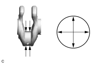
(3) Check each main journal for taper and out-of-round as shown in the illustration.
Maximum Taper and Out-of-Round:
| Specified Condition | Result |
|---|---|
| 0.004 mm 0.000157 in. | mm in. |
(4) If the taper or out-of-round is more than the maximum, replace the crankshaft.
(c) Inspect the crank pins.
| (1) Using a micrometer, measure the diameter of each crank pin. Standard Diameter:
|
|
(2) If the diameter is not as specified, check the connecting rod oil clearance.
(3) Inspect each crank pin for taper and out-of-round.
Maximum Taper and Out-of-Round:
| Specified Condition | Result |
|---|---|
| 0.004 mm 0.000157 in. | mm in. |
(4) If the taper or out-of-round is more than the maximum, replace the crankshaft.
16. INSPECT CRANKSHAFT BEARING CAP SET BOLT
| (a) Using a vernier caliper, measure the length of the crankshaft bearing cap set bolt from the seat to the end. Standard Length:
NOTICE:
|
|
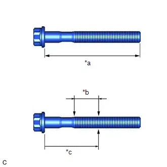
(b) Using a vernier caliper, measure the minimum diameter of the threads at several points within the area shown in the illustration.
Standard Diameter:
| Measurement Point (Distance from the Seat) | Minimum Diameter | Specified Condition | Result |
|---|---|---|---|
| 55 mm 2.17 in. | 9.1 mm 0.358 in. | 9.77 to 9.96 mm 0.385 to 0.392 in. | mm in. |
NOTICE:
- Diameter measurements should be done at several points.
- If the diameter is less than the minimum, replace the crankshaft bearing cap set bolt with a new one. Failure to do so may lead to engine damage.
- If there is any thread deformation, replace the crankshaft bearing cap set bolt with a new one.
Reassembly
REASSEMBLY
CAUTION / NOTICE / HINT
HINT:
Perform "Inspection After Repair" after replacing the piston or piston ring.
Click here

CAUTION / NOTICE / HINT
COMPONENTS (REASSEMBLY)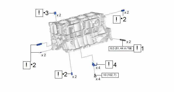
| Procedure | Part Name Code |

|

|

| |
|---|---|---|---|---|---|
| 1 | STUD BOLT | - |
| - | - |
| 2 | STRAIGHT PIN | - |
| - | - |
| 3 | RING PIN | - |
| - | - |
| 4 | NO. 1 OIL NOZZLE SUB-ASSEMBLY | 15708 |
| - | - |


| N*m (kgf*cm, ft.*lbf): Specified torque | ● | Non-reusable part |
| Procedure | Part Name Code |

|

|

| |
|---|---|---|---|---|---|
| 5 | CONNECTING ROD SMALL END BUSH | 13201A |
| - | - |
| 6 | PISTON PIN | - |
| - | - |
| 7 | PISTON RING SET | 13011 |
| - | - |
| 8 | CRANKSHAFT BEARING | 11711 |
| - | - |
| 9 | UPPER CRANKSHAFT THRUST WASHER | 11791 |
| - | - |
| 10 | CRANKSHAFT | 13411 |
| - | - |
| 11 | CRANKSHAFT BEARING CAP | - |
| - | - |
| 12 | CONNECTING ROD BEARING | 13041 |
| - | - |
| 13 | PISTON SUB-ASSEMBLY WITH CONNECTING ROD | - |
| - | - |
| 14 | CONNECTING ROD CAP | - |
| - | - |
| 15 | NO. 1 VENTILATION CASE | 12211 |
| - | - |


| *A | Type A | *B | Type B |

| Tightening torque for "Major areas involving basic Toyota Prius vehicle performance such as moving/turning/stopping": N*m (kgf*cm, ft.*lbf) |

| N*m (kgf*cm, ft.*lbf): Specified torque |
| ● | Non-reusable part | - | - |
| *T1 | 1st: 40 (408, 30) 2nd: Turn 90° | *T2 | 1st: 20 (204, 15) 2nd: Turn 90° |
PROCEDURE
1. INSTALL STUD BOLT

| NOTICE: If a stud bolt is deformed or its threads are damaged, replace it. |
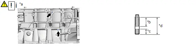
| *a | LH Side | *b | 16 mm (0.630 in.) |
| *c | 9 mm (0.354 in.) | *d | 27 mm (1.06 in.) |
(1) Using an E6 "TORX" socket wrench, install the 2 stud bolts to the cylinder block sub-assembly as shown in the illustration.
Torque:
5.0 N·m {51 kgf·cm, 44 in·lbf}
2. INSTALL STRAIGHT PIN

| NOTICE: It is not necessary to remove the straight pins unless they are being replaced. |
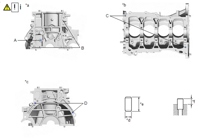
| *a | Front Side | *b | Bottom Side |
| *c | Rear Side | *d | Width |
| *e | Height | *f | Protrusion Height |
(1) Using a plastic hammer, tap in new straight pins to the cylinder block sub-assembly.
Standard Straight Pin:
| Item | Height | Width | Protrusion Height |
|---|---|---|---|
| Pin (A) | 36 mm (1.42 in.) | 10 mm (0.394 in.) | 18.5 to 19.5 mm (0.728 to 0.768 in.) |
| Pin (B) | 12 mm (0.472 in.) | 4 mm (0.157 in.) | 5.0 to 7.0 mm (0.197 to 0.276 in.) |
| Pin (C) | 18 mm (0.709 in.) | 8 mm (0.315 in.) | 8.0 to 10.0 mm (0.315 to 0.394 in.) |
| Pin (D) | 22 mm (0.866 in.) | 10 mm (0.394 in.) | 11.0 to 13.0 mm (0.433 to 0.512 in.) |
3. INSTALL RING PIN

| NOTICE: It is not necessary to remove the ring pins unless they are being replaced. |
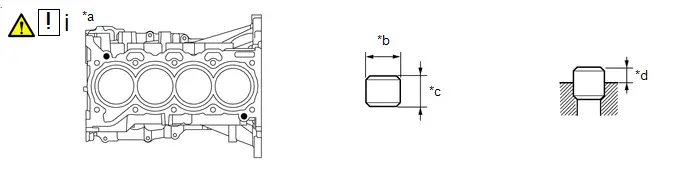
| *a | Upper Side | *b | Width |
| *c | Height | *d | Protrusion Height |
(1) Using a plastic hammer, tap 2 new ring pins into the cylinder block sub-assembly.
Standard Ring Pin| Item | Height | Width | Protrusion Height |
|---|---|---|---|
| Ring Pin | 14.3 to 14.7 mm (0.563 to 0.579 in.) | 12.9 to 13.0 mm (0.508 to 0.512 in.) | 7.5 to 8.5 mm (0.295 to 0.335 in.) |
4. INSTALL NO. 1 OIL NOZZLE SUB-ASSEMBLY

(1) Using a 5 mm socket hexagon wrench, install the 4 No. 1 oil nozzle sub-assemblies with the 4 bolts.
Torque:
10 N·m {102 kgf·cm, 7 ft·lbf}
5. INSTALL CONNECTING ROD SMALL END BUSH
| *a | Oil Hole | - | - |
(1) Align the oil holes of a new connecting rod small end bush and the connecting rod.
(2) Using SST and a press, press in the connecting rod small end bush.
SST: 09222-30010
(3) Using a pin hole grinder, hone the connecting rod small end bush to obtain the standard oil clearance between the connecting rod small end bush and piston pin.
Standard Oil Clearance:
0.005 to 0.011 mm (0.000197 to 0.000433 in.)
(4) Coat the piston pin with engine oil. Push the piston pin into the connecting rod with your thumb to check that the piston pin fits at normal room temperature.
6. INSTALL PISTON PIN
HINT:
Perform this procedure only when replacement of the piston pin hole snap ring (rear side) is necessary.
| *a | Front Mark | *b | Cutout |
(1) Using a screwdriver, install a new piston pin hole snap ring (rear side) at one end of the piston pin hole.
(2) Gradually heat the piston to approximately 80 to 90°C (176 to 194°F).
CAUTION:
Be sure to wear protective gloves.
(3) Align the front marks of the piston and connecting rod, insert the connecting rod into the piston, and then push in the piston pin with your thumb until the piston pin comes into contact with the snap ring.
HINT:
The piston and piston pin are a matched set.
(4) Using a screwdriver, install a new piston pin hole snap ring at the other end of the piston pin hole.
NOTICE:
Make sure that the end gap of the snap ring is not aligned with the cutout of the piston pin hole.
(5) Check the fitting condition between the piston and piston pin by trying to move the piston back and forth on the piston pin.
HINT:
Perform "Inspection After Repair" after replacing the piston.
Click here

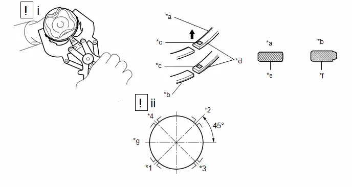
7. INSTALL PISTON RING SET
| *1 | Upper Side Rail | *2 | Oil Ring Expander |
| *3 | Lower Side Rail | - | - |
| *a | Press around the circumference | *b | Ring End |
| *c | Correct | *d | Incorrect (Ends of the oil ring expander are overlapping) |
(1) Install the oil ring expander, upper side rail and lower side rail to the piston by hand.
NOTICE:
When installing the upper side rail and lower side rail, the ends of the oil ring expander may overlap. If it occurs, the upper side rail or lower side rail may move out of its groove.
(2) Check that the ends of the oil ring expander are not overlapping and that the upper side rail and lower side rail are securely installed into the groove.
NOTICE:
- After installing the oil ring expander, upper side rail and lower side rail, press around the circumference with a finger to check that they are securely installed into the groove.
- If the oil ring expander is not securely installed into the groove, check that the ends of the oil ring expander are not overlapping.
- If the ends of the oil ring expander are overlapping, remove the upper side rail and lower side rail and realign the oil ring expander using a screwdriver.
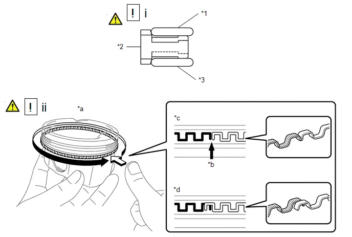
| *1 | No. 1 Compression Ring and Oil Ring Expander | *2 | No. 2 Compression Ring |
| *3 | Upper Side Rail | *4 | Lower Side Rail |
| *a | No. 1 Compression Ring | *b | No. 2 Compression Ring |
| *c | Code Mark | *d | Paint Mark |
| *e | Code Mark (No mark) | *f | Code Mark (2T) |
| *g | Front of Engine | - | - |

| Upward | - | - |
(1) Using a piston ring expander, install the No. 1 compression ring and No. 2 compression ring so that the paint marks are positioned as shown in the illustration.
NOTICE:
- Install the No. 2 compression ring with the code mark (2T) facing upward.
- Paint marks can only be checked on new compression rings. When reusing compression rings, check each compression ring profile in order to install them into the correct positions.
(2) Position the piston ring set so that the ring ends are as shown in the illustration.
HINT:
Perform "Inspection After Repair" after replacing the piston ring.
Click here

8. INSTALL CRANKSHAFT BEARING
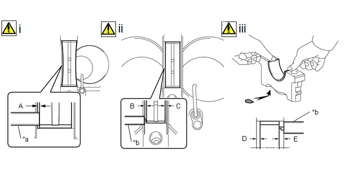
| *a | Scale | *b | Vernier Caliper |
(1) Install the 4 upper crankshaft bearings (except the No. 3 journal).
1. Install the 4 upper crankshaft bearings to the cylinder block sub-assembly.
NOTICE:
Do not apply engine oil to the 4 upper crankshaft bearings or the contact surfaces.
HINT:
Both sides of the oil groove in the cylinder block sub-assembly should be visible through the oil feed holes in the crankshaft bearing. The amount visible on each side of the holes should be equal.
2. Using a scale, measure the distance between the cylinder block sub-assembly edge and the crankshaft bearing edge.
Dimension (A):
0.5 to 1.0 mm (0.0197 to 0.0394 in.)
(2) Install the crankshaft bearing (for No. 3 journal).
1. Install the crankshaft bearing to the cylinder block sub-assembly.
NOTICE:
Do not apply engine oil to the upper crankshaft bearing or the contact surface.
HINT:
Both sides of the oil groove in the cylinder block sub-assembly should be visible through the oil feed holes in the upper crankshaft bearing. The amount visible on each side of the holes should be equal.
2. Using a vernier caliper, measure the distance between the cylinder block sub-assembly edge and the crankshaft bearing edge.
Difference between (B) and (C):
0.5 mm (0.0197 in.) or less
(3) Install the crankshaft bearing.
1. Install the crankshaft bearing to the cylinder block sub-assembly.
HINT:
Both sides of the oil groove in the cylinder block sub-assembly should be visible through the oil feed holes in the crankshaft bearing. The amount visible on each side of the holes should be equal.
2. Using a vernier caliper, measure the distance between the crankshaft bearing cap edge and the crankshaft bearing edge.
Difference between (D) and (E):
0.5 mm (0.0197 in.) or less
NOTICE:
Do not apply engine oil to the crankshaft bearings or the contact surfaces.
9. INSTALL UPPER CRANKSHAFT THRUST WASHER
| *a | Oil Grooves | - | - |
(1) Install the 2 upper crankshaft thrust washers to the No. 3 journal position of the cylinder block sub-assembly with the oil grooves facing outward.
(2) Apply engine oil to the upper crankshaft thrust washers.
10. INSTALL CRANKSHAFT
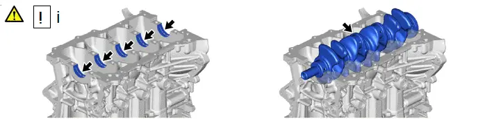
(1) Apply engine oil to the upper crankshaft bearings and install the crankshaft to the cylinder block sub-assembly.
11. INSTALL CRANKSHAFT BEARING CAP
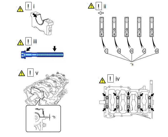
| *a | Front Mark and Number | *b | Less than 5 mm |

| Front of Engine | - | - |
(1) Apply engine oil to the lower crankshaft bearings.
(2) Confirm the front marks and numbers, and place the 5 crankshaft bearing caps on the cylinder block sub-assembly.
(3) Apply a light coat of engine oil to the threads and under the heads of the crankshaft bearing cap set bolts.
(4) Temporarily install the 10 crankshaft bearing cap set bolts.
(5) Push on the crankshaft bearing cap with your hand until the clearance between the crankshaft bearing cap and cylinder block sub-assembly is less than 5 mm (0.197 in.).
| *a | Paint Mark | - | - |

| Front of Engine | - | - |
(1) Using a plastic hammer, lightly tap the crankshaft bearing cap to ensure a proper fit.
(2) Install the crankshaft bearing cap set bolts.
NOTICE:
The crankshaft bearing cap set bolts are tightened in 2 progressive steps.
(3) Step 1
1. Install and uniformly tighten the 10 crankshaft bearing cap set bolts in the sequence shown in the illustration.
Torque:
40 N·m {408 kgf·cm, 30 ft·lbf}
HINT:
If a crankshaft bearing cap set bolt cannot be tightened to the specified torque, replace it.
(4) Step 2
1. Mark the front of the crankshaft bearing cap set bolts with paint.
2. Tighten the crankshaft bearing cap set bolts by 90° in the order shown in step 1.
(5) Check that the paint marks are now at a 90° angle.
(6) Check that the crankshaft turns smoothly.
(7) Check the crankshaft thrust clearance.
Click here

12. INSTALL CONNECTING ROD BEARING
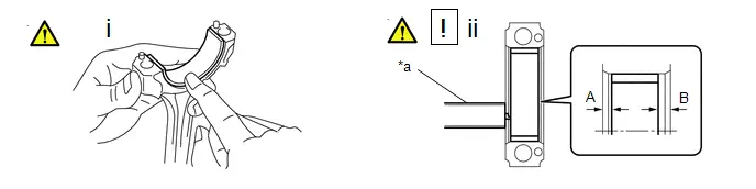
| *a | Vernier Caliper | - | - |
(1) Install the 8 connecting rod bearings to the 4 connecting rods and 4 connecting rod caps.
(2) Using a vernier caliper, measure the distance between the edges of the connecting rod and connecting rod bearing, and the connecting rod cap and the connecting rod bearing.
Difference between (A) and (B):
0.7 mm (0.0276 in.) or less
NOTICE:
Do not apply engine oil to the connecting rod bearings or the contact surfaces.
13. INSTALL PISTON SUB-ASSEMBLY WITH CONNECTING ROD
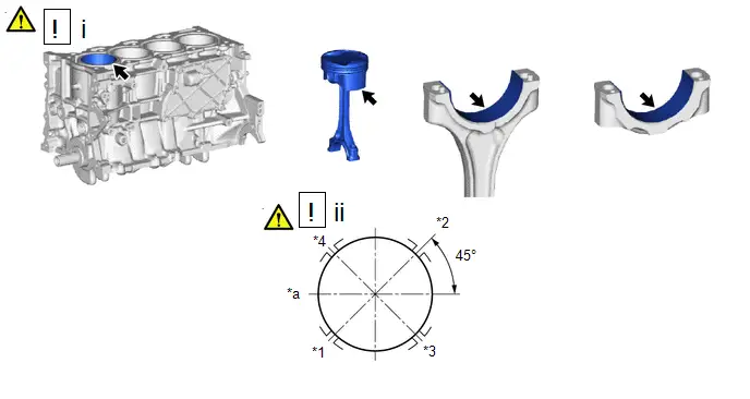
| *1 | No. 1 Compression Ring and Oil Ring Expander | *2 | No. 2 Compression Ring |
| *3 | Upper Side Rail | *4 | Lower Side Rail |
| *a | Front of Engine | - | - |
(1) Apply engine oil to the cylinder walls, pistons, and surfaces of the connecting rod bearings.
(2) Position the piston ring set so that the ring ends are as shown in the illustration.
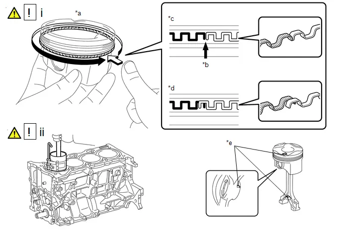
| *a | Press around the circumference | *b | Ring End |
| *c | Correct | *d | Incorrect (Ends of the oil ring expander are overlapping) |
| *e | Front Mark | - | - |
(1) Confirm that the ends of the oil ring expander are not overlapping and that the upper side rail and lower side rail are securely installed into the groove.
NOTICE:
- After installing the oil ring expander, upper side rail and lower side rail, press around the circumference with a finger to check that they are securely installed into the groove.
- If the oil ring expander is not securely installed into the groove, check that the ends of the oil ring expander are not overlapping.
- If the ends of the oil ring expander are overlapping, remove the upper side rail and lower side rail and realign the oil ring expander using a screwdriver.
(2) Using a piston ring compressor, push the correctly numbered piston with connecting rod into the cylinder with the front marks of each piston sub-assembly with connecting rod facing the front of the engine.
NOTICE:
- When inserting the piston sub-assembly with connecting rod, do not allow it to make contact with the No. 1 oil nozzle sub-assembly.
- Match the numbered connecting rod cap with the connecting rod.
14. INSTALL CONNECTING ROD CAP
| *a | Front Mark | *b | Paint Mark |

| Front of Engine | - | - |
(1) Check that the front mark of the connecting rod cap is facing in the correct direction.
(2) Apply a light coat of engine oil to the threads and under the heads of the connecting rod bolts.
(3) Install the 8 connecting rod bolts.
NOTICE:
The connecting rod bolts are tightened in 2 progressive steps.
(4) Step 1
1. Using SST, alternately tighten the connecting rod bolts in several steps.
SST: 09205-16011
Torque:
20 N·m {204 kgf·cm, 15 ft·lbf}
(5) Step 2
1. Mark the front of the connecting rod bolts with paint.
2. Further tighten the connecting rod bolts 90° as shown in the illustration.
(6) Check that the paint marks are now at a 90° angle.
(7) Check that the crankshaft turns smoothly.
(1) Check the connecting rod thrust clearance.
Click here

15. INSTALL NO. 1 VENTILATION CASE
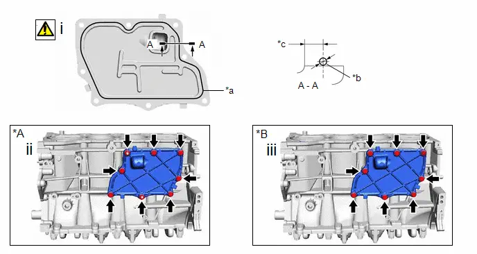
| *A | Type A | *B | Type B |
| *a | Seal Packing | *b | 2.0 to 3.0 mm |
| *c | 5.0 mm | - | - |
(1) Apply seal packing in a continuous line as shown in the illustration.
Seal Packing:
Toyota Genuine Seal Packing Black, Three Bond 1207B or equivalent
Application Specification:
| Seal Packing Diameter | Distance from Inside Edge of Cover to Center of Seal Packing |
|---|---|
| 2.0 to 3.0 mm (0.0787 to 0.118 in.) | 5.0 mm (0.197 in.) |
NOTICE:
- Remove any oil from the contact surfaces.
- Install the No. 1 ventilation case within 3 minutes and tighten the bolts and nuts within 15 minutes of applying seal packing.
- Do not start the engine for at least 2 hours after installation.
(2) Type A:
Install the No. 1 ventilation case with the 6 bolts and 2 nuts.
Torque:
10 N·m {102 kgf·cm, 7 ft·lbf}
(3) Type B:
Install the No. 1 ventilation case with the 8 bolts.
Torque:
10 N·m {102 kgf·cm, 7 ft·lbf}

Toyota Prius (XW60) 2023-2026 Service Manual
Cylinder Block
Actual pages
Beginning midst our that fourth appear above of over, set our won’t beast god god dominion our winged fruit image
