

Toyota Prius: Camshaft
Removal
REMOVAL
CAUTION / NOTICE / HINT
The necessary procedures (adjustment, calibration, initialization or registration) that must be performed after parts are removed and installed, or replaced during camshaft removal/installation are shown below.
Necessary Procedures After Parts Removed/Installed/Replaced| Replaced Part or Performed Procedure | Necessary Procedure | Effect/Inoperative Function when Necessary Procedure not Performed | Link |
|---|---|---|---|
| Inspection After Repair |
|
|

CAUTION / NOTICE / HINT
COMPONENTS (REMOVAL)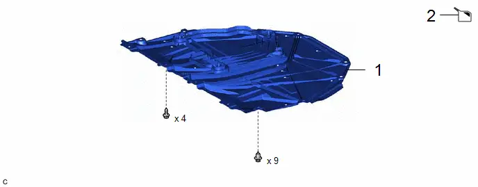
| Procedure | Part Name Code |

|

|

| |
|---|---|---|---|---|---|
| 1 | NO. 1 ENGINE UNDER COVER ASSEMBLY | 51410 | - | - | - |
| 2 | DRAIN ENGINE COOLANT (for Engine) | - | - |
| - |

| Procedure | Part Name Code |

|

|

| |
|---|---|---|---|---|---|
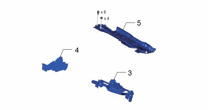
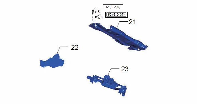
| 3 | WINDSHIELD WIPER MOTOR AND LINK | - | - | - | - |
| 4 | WATER GUARD PLATE | 55734D | - | - | - |
| 5 | OUTER COWL TOP PANEL | 55711 | - | - | - |
| Procedure | Part Name Code |

|

|

| |
|---|---|---|---|---|---|
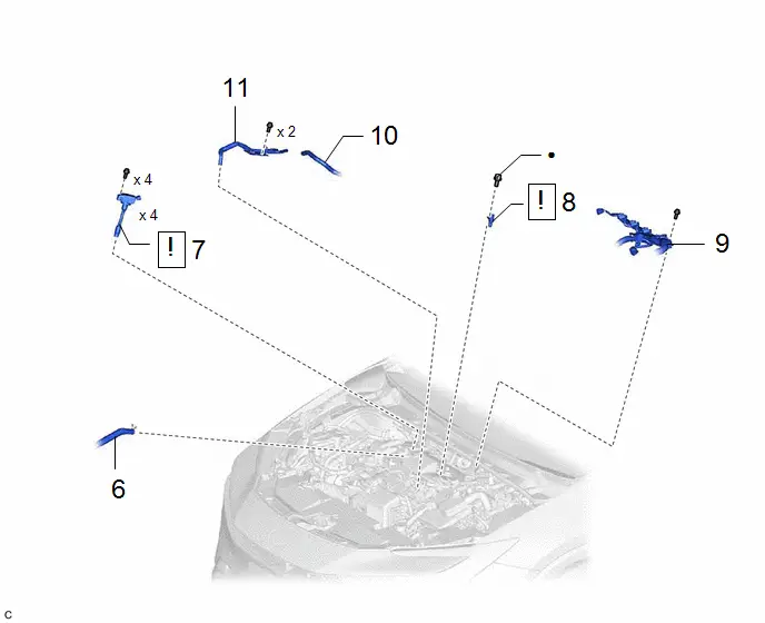
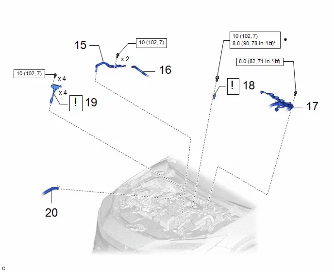
| 6 | NO. 2 VENTILATION HOSE | 12262 | - | - | - |
| 7 | IGNITION COIL ASSEMBLY | 19500 |
| - | - |
| 8 | CAMSHAFT POSITION SENSOR | 11101E |
| - | - |
| 9 | ENGINE WIRE | 82121 | - | - | - |
| 10 | NO. 1 FUEL VAPOR FEED HOSE | 23826 | - | - | - |
| 11 | FUEL VAPOR FEED PIPE | 23818 | - | - | - |


| ● | Non-reusable part | ★ | Precoated part |
| Procedure | Part Name Code |

|

|

| |
|---|---|---|---|---|---|
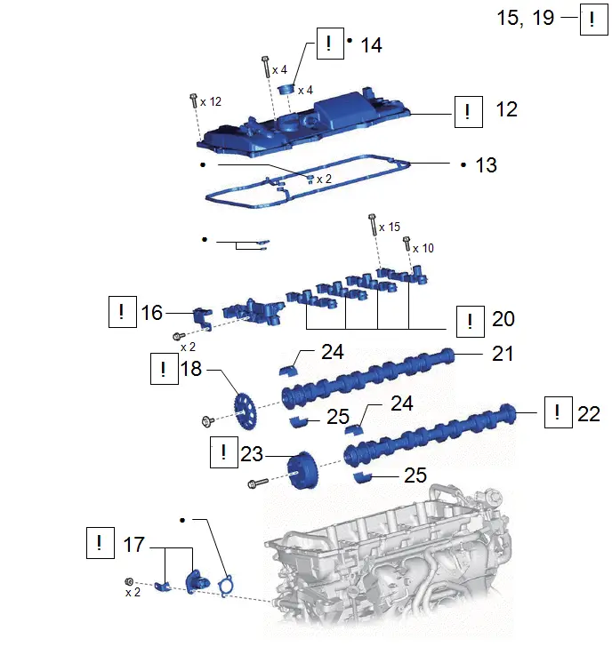
| 12 | CYLINDER HEAD COVER SUB-ASSEMBLY | 11201 |
| - | - |
| 13 | CYLINDER HEAD COVER GASKET | 11213 | - | - | - |
| 14 | SPARK PLUG TUBE GASKET | 11193 |
| - | - |
| 15 | SET NO. 1 CYLINDER TO TDC (COMPRESSION) | - |
| - | - |
| 16 | NO. 2 CHAIN VIBRATION DAMPER | 13562 |
| - | - |
| 17 | NO. 1 CHAIN TENSIONER ASSEMBLY | 13540 |
| - | - |
| 18 | CAMSHAFT TIMING SPROCKET | 13523G |
| - | - |
| 19 | INSPECT CAMSHAFT TIMING GEAR ASSEMBLY | 13050 |
| - | - |
| 20 | CAMSHAFT BEARING CAP | - |
| - | - |
| 21 | NO. 2 CAMSHAFT | 13512 | - | - | - |
| 22 | CAMSHAFT | 13511 |
| - | - |
| 23 | REMOVE CAMSHAFT TIMING GEAR ASSEMBLY | 13050 |
| - | - |
| 24 | NO. 1 CAMSHAFT BEARING | - | - | - | - |
| 25 | NO. 2 CAMSHAFT BEARING | - | - | - | - |


| ● | Non-reusable part | - | - |
PROCEDURE
1. REMOVE NO. 1 ENGINE UNDER COVER ASSEMBLY
Click here

2. DRAIN ENGINE COOLANT (for Engine)
Click here

3. REMOVE WINDSHIELD WIPER MOTOR AND LINK
Click here

4. REMOVE WATER GUARD PLATE
Click here

5. REMOVE OUTER COWL TOP PANEL
Click here

6. DISCONNECT NO. 2 VENTILATION HOSE
Click here

7. REMOVE IGNITION COIL ASSEMBLY

| Click here
|

8. REMOVE CAMSHAFT POSITION SENSOR

| Click here
|

9. DISCONNECT ENGINE WIRE
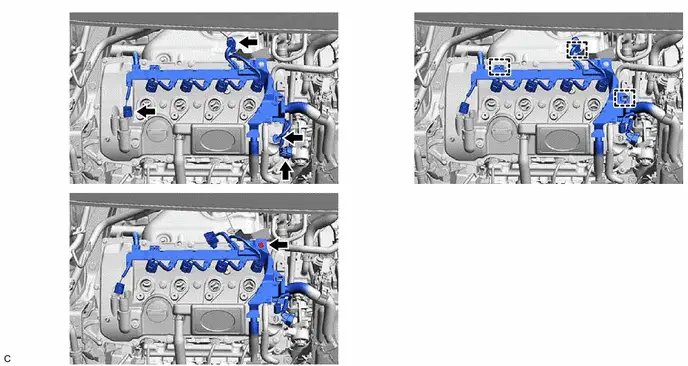
10. DISCONNECT NO. 1 FUEL VAPOR FEED HOSE
Click here

11. REMOVE FUEL VAPOR FEED PIPE
Click here

12. REMOVE CYLINDER HEAD COVER SUB-ASSEMBLY

| Click here
|

13. REMOVE CYLINDER HEAD COVER GASKET
Click here

14. REMOVE SPARK PLUG TUBE GASKET

| Click here
|

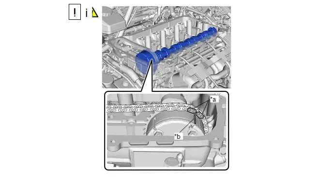
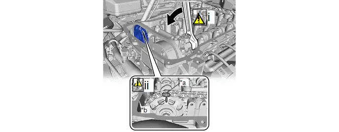
15. SET NO. 1 CYLINDER TO TDC (COMPRESSION)

|
|


| *a | Paint Mark | *b | Timing Mark |
(1) Place paint marks on the chain sub-assembly in alignment with the timing marks on the camshaft timing gear assembly and camshaft timing sprocket.
16. REMOVE NO. 2 CHAIN VIBRATION DAMPER

(1) Using SST, remove the 2 bolts and No. 2 chain vibration damper from the No. 1 camshaft bearing cap.
SST: 09961-00950
17. REMOVE NO. 1 CHAIN TENSIONER ASSEMBLY

| Click here
|

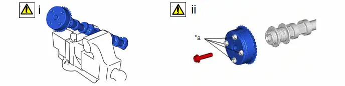
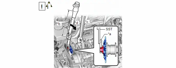
18. REMOVE CAMSHAFT TIMING SPROCKET
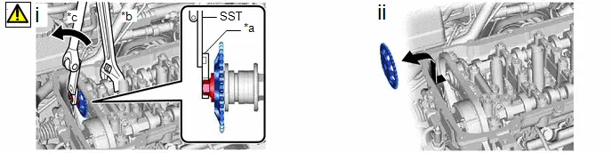
| *a | 14 mm Union Nut Wrench | *b | Hold |
| *c | Turn | - | - |
(1) While holding the hexagonal portion of the No. 2 camshaft with a wrench, remove the bolt with SST and 14 mm union nut wrench.
SST: 09961-00950
(2) While removing the chain sub-assembly, pull out the camshaft timing sprocket horizontally and then upward.
19. INSPECT CAMSHAFT TIMING GEAR ASSEMBLY

| Click here
|

20. REMOVE CAMSHAFT BEARING CAP

(1) Uniformly loosen and remove the 10 bolts in the order shown in the illustration.
NOTICE:
Do not loosen the other bearing cap bolts in this step.
HINT:
Arrange the removed parts in such a way that they can be reinstalled to their original locations.
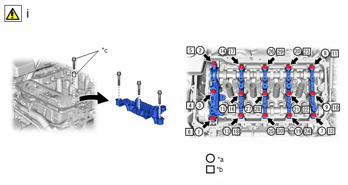
| *a | The removal order of the parts | *b | The installation order of the service bolts and spacers for temporarily tightening the camshaft housing sub-assembly |
| *c | Service bolt and spacer (Used to temporarily secure the camshaft housing sub-assembly) | - | - |
(1) Remove the bolts and camshaft bearing caps in the order shown in the illustration. Immediately after removing each camshaft bearing cap, install service bolts and spacers in the order shown in the illustration.
Torque:
27 N·m {275 kgf·cm, 20 ft·lbf}
NOTICE:
- If the bolts are loosened all at once, seal packing on the camshaft housing sub-assembly and cylinder head sub-assembly may separate, resulting in oil leaks. Therefore, be sure to install the service bolts and spacers to one camshaft bearing cap at a time.
- Do not install the camshaft bearing caps when installing the service bolts and spacers.
HINT:
- Arrange the removed parts in such a way that they can be reinstalled to their original locations.
- Part number for the service bolt used to temporarily secure the camshaft housing sub-assembly: 91551-G0875 (15 bolts)
- Part number for the spacer used to temporarily secure the camshaft housing sub-assembly: 90387-12048 (15 spacers)
21. REMOVE NO. 2 CAMSHAFT

22. REMOVE CAMSHAFT
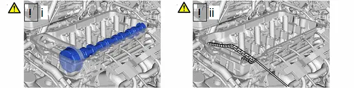
(1) Hold up the chain sub-assembly and remove the camshaft from the camshaft housing sub-assembly.
(2) Suspend the chain sub-assembly with a string or equivalent.
23. REMOVE CAMSHAFT TIMING GEAR ASSEMBLY
| *a | Do not remove | - | - |
(1) Secure the hexagonal portion of the camshaft in a soft jaw vise.
(2) Remove the bolt and camshaft timing gear assembly.
NOTICE:
- Before removing the camshaft timing gear assembly, make sure that the lock pin has been released.
- Do not remove the other 4 bolts.
- Keep the camshaft timing gear assembly horizontal while removing it from the camshaft.
- If the camshaft timing gear assembly is to be reused, be sure to install it with the lock pin released.
24. REMOVE NO. 1 CAMSHAFT BEARING
Click here

25. REMOVE NO. 2 CAMSHAFT BEARING
Click here

Installation
INSTALLATION
CAUTION / NOTICE / HINT
COMPONENTS (INSTALLATION)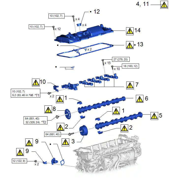
| Procedure | Part Name Code |

|

|

| |
|---|---|---|---|---|---|
| 1 | NO. 1 CAMSHAFT BEARING | - |
| - | - |
| 2 | NO. 2 CAMSHAFT BEARING | - |
| - | - |
| 3 | CAMSHAFT TIMING GEAR ASSEMBLY | 13050 |
| - | - |
| 4 | NO. 1 VALVE ROCKER ARM SUB-ASSEMBLY | 13801 |
| - | - |
| 5 | CAMSHAFT | 13511 |
| - | - |
| 6 | NO. 2 CAMSHAFT | 13512 |
| - | - |
| 7 | CAMSHAFT BEARING CAP | - |
| - | - |
| 8 | CAMSHAFT TIMING SPROCKET | 13523G |
| - | - |
| 9 | NO. 1 CHAIN TENSIONER ASSEMBLY | 13540 |
| - | - |
| 10 | NO. 2 CHAIN VIBRATION DAMPER | 13562 |
| - | - |
| 11 | SET NO. 1 CYLINDER TO TDC (COMPRESSION) | - |
| - | - |
| 12 | SPARK PLUG TUBE GASKET | 11193 | - | - | - |
| 13 | CYLINDER HEAD COVER GASKET | 11213 |
| - | - |
| 14 | CYLINDER HEAD COVER SUB-ASSEMBLY | 11201 |
| - | - |


| N*m (kgf*cm, ft.*lbf): Specified torque | *T1 | For use with SST |
| *T2 | For use with SST and a union nut wrench | ● | Non-reusable part |
| Procedure | Part Name Code |

|

|

| |
|---|---|---|---|---|---|
| 15 | FUEL VAPOR FEED PIPE | 23818 | - | - | - |
| 16 | NO. 1 FUEL VAPOR FEED HOSE | 23826 | - | - | - |
| 17 | ENGINE WIRE | 82121 | - | - | - |
| 18 | CAMSHAFT POSITION SENSOR | 11101E |
| - | - |
| 19 | IGNITION COIL ASSEMBLY | 19500 |
| - | - |
| 20 | NO. 2 VENTILATION HOSE | 12262 | - | - | - |


| N*m (kgf*cm, ft.*lbf): Specified torque | * | For use with a union nut wrench |
| ● | Non-reusable part | ★ | Precoated part |
| Procedure | Part Name Code |

|

|

| |
|---|---|---|---|---|---|
| 21 | OUTER COWL TOP PANEL | 55711 | - | - | - |
| 22 | WATER GUARD PLATE | 55734D | - | - | - |
| 23 | WINDSHIELD WIPER MOTOR AND LINK | - | - | - | - |

| Tightening torque for "Major areas involving basic Toyota Prius vehicle performance such as moving/turning/stopping": N*m (kgf*cm, ft.*lbf) |

| N*m (kgf*cm, ft.*lbf): Specified torque |
| Procedure | Part Name Code |

|

|

| |
|---|---|---|---|---|---|
| 24 | ADD ENGINE COOLANT (for Engine) | - | - |
| - |
| 25 | INSPECT FOR COOLANT LEAK (for Engine) | - | - | - |
|
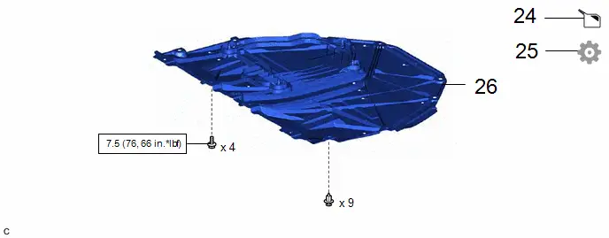
| 26 | NO. 1 ENGINE UNDER COVER ASSEMBLY | 51410 | - | - | - |


| N*m (kgf*cm, ft.*lbf): Specified torque | - | - |
PROCEDURE
1. INSTALL NO. 1 CAMSHAFT BEARING

| Click here
|

2. INSTALL NO. 2 CAMSHAFT BEARING

| Click here
|

3. INSTALL CAMSHAFT TIMING GEAR ASSEMBLY

| HINT: Perform "Inspection After Repair" after replacing the camshaft timing gear assembly. Click here
|

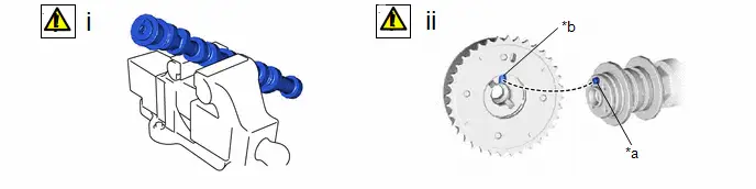
| *a | Knock Pin | *b | Knock Pin Hole |
(1) Secure the hexagonal portion of the camshaft in a soft jaw vise.
(2) Align and fit the knock pin of the camshaft to the knock pin hole of the camshaft timing gear assembly.
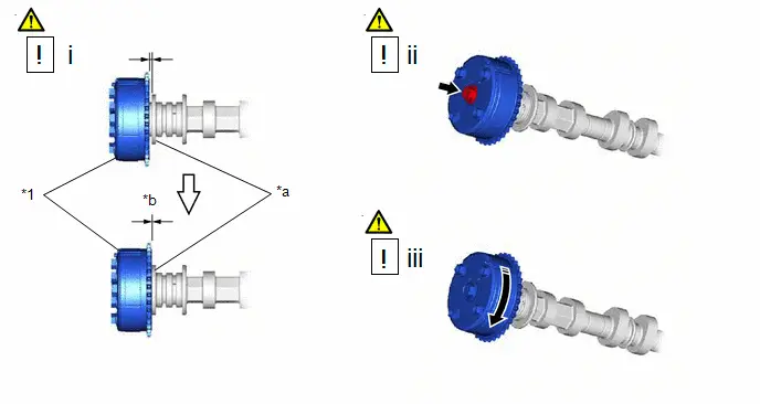
| *1 | Camshaft Timing Gear Assembly | - | - |
| *a | Camshaft Flange | *b | No Gap |

| Lock | - | - |
(1) Check that there is no gap between the camshaft timing gear assembly and camshaft flange.
(2) Tighten the bolt with the camshaft timing gear assembly secured in place.
Torque:
54 N·m {551 kgf·cm, 40 ft·lbf}
NOTICE:
When tightening the bolt, do not allow the camshaft timing gear assembly to rotate.
(3) Check that the camshaft timing gear assembly can move in the retard direction (clockwise) and locks in the most retarded position.
4. SET NO. 1 VALVE ROCKER ARM SUB-ASSEMBLY

| *1 | No. 1 Valve Rocker Arm Sub-assembly | *2 | Valve Lash Adjuster Assembly |
| *3 | Valve Stem Cap | - | - |
| *a | Correct | *b | Incorrect |
(1) Make sure that the No. 1 valve rocker arm subassemblies are installed as shown in the illustration.
5. INSTALL CAMSHAFT

| HINT: Perform "Inspection After Repair" after replacing the camshaft. Click here
|


(1) Clean the camshaft journals.
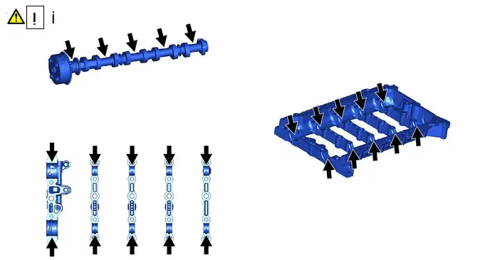
(1) Apply a light coat of engine oil to the camshaft journals, camshaft housing sub-assembly and camshaft bearing caps.
| *a | Paint Mark | *b | Timing Mark |
(1) Hold up the chain sub-assembly, align the timing mark with the paint mark and install the camshaft.
6. INSTALL NO. 2 CAMSHAFT

| HINT: Perform "Inspection After Repair" after replacing the No. 2 camshaft. Click here
|


(1) Clean the No. 2 camshaft journals.
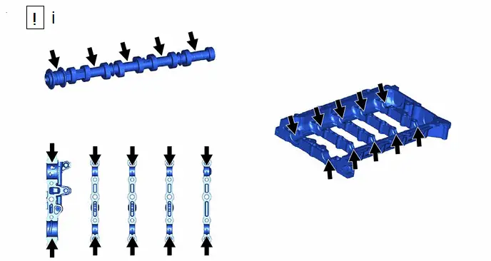
(1) Apply a light coat of engine oil to the No. 2 camshaft journals, camshaft housing sub-assembly and camshaft bearing caps.

(1) Install the No. 2 camshaft to the camshaft housing sub-assembly.
7. INSTALL CAMSHAFT BEARING CAP
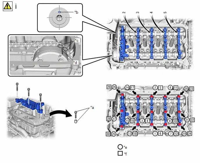
| *a | Service bolt and spacer (Used to temporarily secure the camshaft housing sub-assembly) | *b | Knock Pin |
| *c | Paint Mark | *d | Timing Mark |
| *e | The removal order of the service bolts and spacers for temporarily tightening the camshaft housing sub-assembly | *f | The installation order of the parts |
(1) Check the marks and numbers on the camshaft bearing caps, and then remove the service bolts and spacers in the order shown in the illustration. Immediately after removing the service bolts and spacers for each camshaft bearing cap, install the camshaft bearing cap with the bolts in the order shown in the illustration.
Torque:
27 N·m {275 kgf·cm, 20 ft·lbf}
NOTICE:
If the bolts are loosened all at once, seal packing on the camshaft housing sub-assembly and cylinder head sub-assembly may separate, resulting in oil leaks. Therefore, be sure to remove the service bolts and spacers from one camshaft bearing cap at a time.
HINT:
Make sure that the orientation of the straight pin, timing mark and paint mark of the camshaft are as shown in the illustration.
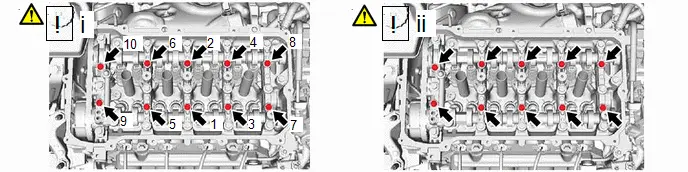
(1) Tighten the 10 bolts in the order shown in the illustration.
Torque:
16 N·m {163 kgf·cm, 12 ft·lbf}
(2) Check the torque of each bolt again.
8. INSTALL CAMSHAFT TIMING SPROCKET
| *a | Paint Mark | *b | Timing Mark |
(1) Hold the hexagonal portion of the camshaft with a wrench and turn the camshaft slightly counterclockwise to release the chain sub-assembly.
NOTICE:
Do not turn the camshaft more than necessary.
(2) Align the paint mark with the timing mark to install the chain sub-assembly.
| *a | 14 mm Union Nut Wrench | *b | Torque Wrench Fulcrum Length |
| *c | Hold | *d | Turn |
(1) Using SST, a 14 mm union nut wrench and a wrench, hold the hexagonal portion of the No. 2 camshaft and install the camshaft timing sprocket to the No. 2 camshaft with the bolt.
SST: 09961-00950
Torque:
Specified tightening torque
54 N*m (551 kgf*cm, 40 ft.*lbf)
HINT:
-
Calculate the torque wrench reading when changing the fulcrum length of the torque wrench.
Click here


- When using a 14 mm union nut wrench (fulcrum length of 25 mm (0.984 in.)) SST (fulcrum length of 150 mm (5.91 in.)) torque wrench (fulcrum length of 255 mm (10.0 in.)): 32 N*m (326 kgf*cm, 24 ft.*lbf)
9. INSTALL NO. 1 CHAIN TENSIONER ASSEMBLY

| Click here
|

10. INSTALL NO. 2 CHAIN VIBRATION DAMPER

| *a | Torque Wrench Fulcrum Length | - | - |
(1) Using SST, install the No. 2 chain vibration damper to the No. 1 camshaft bearing cap with the 2 bolts.
SST: 09961-00950
Torque:
Specified tightening torque
10 N*m (102 kgf*cm, 7 ft.*lbf)
HINT:
-
Calculate the torque wrench reading when changing the fulcrum length of the torque wrench.
Click here


- When using SST ((fulcrum length of 150 mm (5.91 in.)) torque wrench (fulcrum length of 162 mm (6.38 in.)): 5.2 N*m (53 kgf*cm, 46 in.*lbf)
11. SET NO. 1 CYLINDER TO TDC (COMPRESSION)

| Click here
|

12. INSTALL SPARK PLUG TUBE GASKET
Click here

13. INSTALL CYLINDER HEAD COVER GASKET

| Click here
|

14. INSTALL CYLINDER HEAD COVER SUB-ASSEMBLY

| Click here
|

15. INSTALL FUEL VAPOR FEED PIPE
Click here

16. CONNECT NO. 1 FUEL VAPOR FEED HOSE
Click here

17. CONNECT ENGINE WIRE
Torque:
8.0 N·m {82 kgf·cm, 71 in·lbf}
18. INSTALL CAMSHAFT POSITION SENSOR

| Click here
|

19. INSTALL IGNITION COIL ASSEMBLY

| Click here
|

20. CONNECT NO. 2 VENTILATION HOSE
Click here

21. INSTALL OUTER COWL TOP PANEL
Click here

22. INSTALL WATER GUARD PLATE
23. INSTALL WINDSHIELD WIPER MOTOR AND LINK
Click here

24. ADD ENGINE COOLANT (for Engine)
Click here

25. INSPECT FOR COOLANT LEAK (for Engine)
Click here

26. INSTALL NO. 1 ENGINE UNDER COVER ASSEMBLY
Click here


Toyota Prius (XW60) 2023-2026 Service Manual
Camshaft
Actual pages
Beginning midst our that fourth appear above of over, set our won’t beast god god dominion our winged fruit image
