

Toyota Prius: Condenser (for Hev Model)
On-vehicle Inspection
ON-VEHICLE INSPECTION
PROCEDURE
1. INSPECT COOLER CONDENSER ASSEMBLY
(a) If the cooler condenser assembly fins are dirty, clean them with water and dry them with compressed air.
NOTICE:
Do not damage the cooler condenser assembly fins.
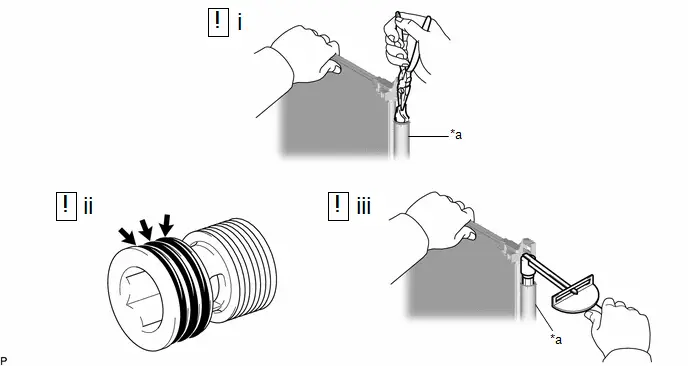
(b) If any cooler condenser assembly fins are bent, straighten them using a screwdriver or pliers.
2. INSPECT FOR REFRIGERANT LEAK
(a) Using a gas leak detector, check the pipe joints for refrigerant leaks.
(b) If a refrigerant leak is detected in a joint, check the torque of the joint.
Removal
REMOVAL
CAUTION / NOTICE / HINT
The necessary procedures (adjustment, calibration, initialization or registration) that must be performed after parts are removed and installed, or replaced during condenser removal/installation are shown below.
Necessary Procedures After Parts Removed/Installed/Replaced| Replaced Part or Performed Procedure | Necessary Procedures | Effect/Inoperative Function When Necessary Procedures are not Performed | Link |
|---|---|---|---|
| *: Even when not replacing the part, it is necessary to perform the specified necessary procedures after installation. | |||
| Front bumper assembly* | Front television camera view adjustment | Panoramic View Monitor System |
|
| Advanced Park |
| ||


CAUTION / NOTICE / HINT
COMPONENTS (REMOVAL)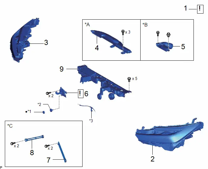
| Procedure | Part Name Code |

|

|

| |
|---|---|---|---|---|---|
| 1 | RECOVER REFRIGERANT FROM REFRIGERATION SYSTEM | - |
| - | - |
| 2 | HEADLIGHT ASSEMBLY LH | - | - | - | - |
| 3 | HEADLIGHT ASSEMBLY RH | - | - | - | - |
| 4 | INLET NO. 1 AIR CLEANER | 17751 | - | - | - |
| 5 | INLET NO. 2 AIR CLEANER | 17752 | - | - | - |
| 6 | HOOD LOCK ASSEMBLY | 53510 |
| - | - |
| 7 | UPPER RADIATOR MOUNTING BRACKET LH | 53254A | - | - | - |
| 8 | UPPER RADIATOR MOUNTING BRACKET RH | 53253D | - | - | - |
| 9 | UPPER RADIATOR SUPPORT SUB-ASSEMBLY | 53205 | - | - | - |


| *A | for M20A-FXS | *B | for 2ZR-FXE |
| *C | w/ Bracket | - | - |
| *1 | HOOD LOCK NUT CAP | *2 | HOOD LOCK BOLT |
| *3 | HOOD LOCK CONTROL CABLE ASSEMBLY | - | - |
| Procedure | Part Name Code |

|

|

| |
|---|---|---|---|---|---|
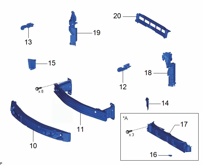
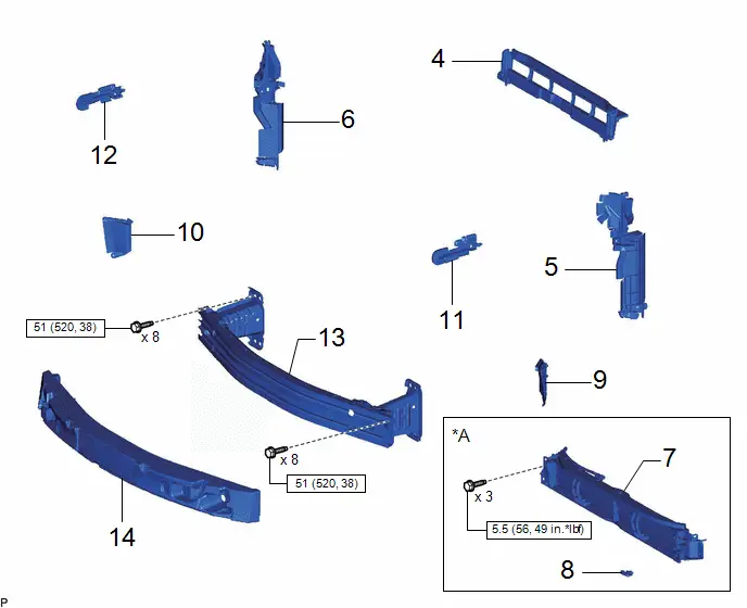
| 10 | FRONT BUMPER ENERGY ABSORBER | 52611 | - | - | - |
| 11 | FRONT BUMPER REINFORCEMENT | - | - | - | - |
| 12 | NO. 3 RADIATOR TO SUPPORT SEAL | 16563C | - | - | - |
| 13 | NO. 2 RADIATOR TO SUPPORT SEAL | 16562K | - | - | - |
| 14 | FRONT RADIATOR SIDE AIR GUIDE PLATE LH | 16695A | - | - | - |
| 15 | FRONT RADIATOR SIDE AIR GUIDE PLATE RH | 16691A | - | - | - |
| 16 | THERMISTOR ASSEMBLY | 88790B | - | - | - |
| 17 | RADIATOR SHUTTER ASSEMBLY | 53180D | - | - | - |
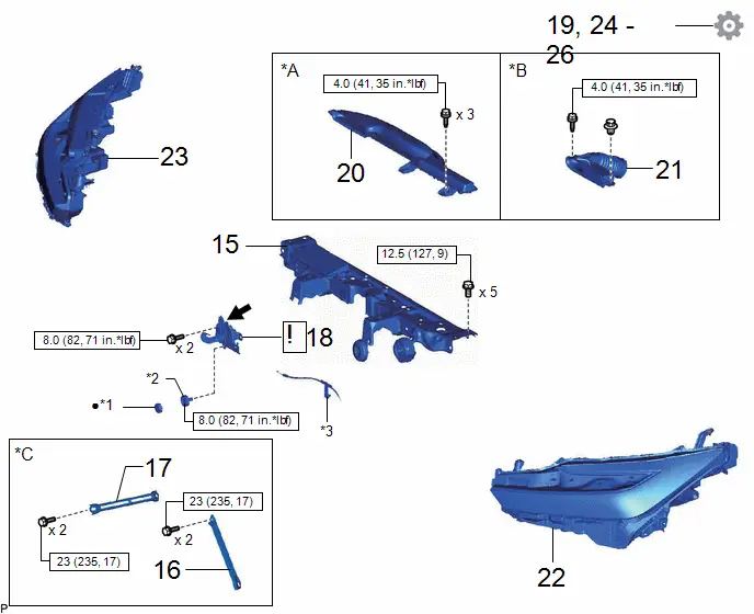
| 18 | NO. 1 RADIATOR AIR GUIDE LH | 16595B | - | - | - |
| 19 | NO. 1 RADIATOR AIR GUIDE RH | 16593B | - | - | - |
| 20 | NO. 2 RADIATOR AIR GUIDE | 16594A | - | - | - |
| *A | w/ Grille Shutter | - | - |
| Procedure | Part Name Code |

|

|

| |
|---|---|---|---|---|---|
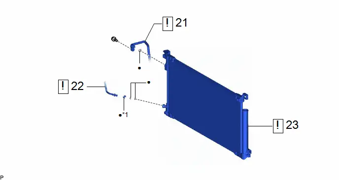
| 21 | DISCHARGE HOSE SUB-ASSEMBLY | 88703 |
| - | - |
| 22 | AIR CONDITIONING TUBE AND ACCESSORY ASSEMBLY | 88710E |
| - | - |
| 23 | COOLER CONDENSER ASSEMBLY | 884A0 |
| - | - |


| *1 | PIPING CLAMP | - | - |
| ● | Non-reusable part | - | - |
PROCEDURE
1. RECOVER REFRIGERANT FROM REFRIGERATION SYSTEM
(a) for HFC-134a (R134a):
Click here

(b) for HFO-1234yf (R1234yf):
Click here


2. REMOVE HEADLIGHT ASSEMBLY LH
Click here

3. REMOVE HEADLIGHT ASSEMBLY RH
(a) Use the same procedure as for the LH side.
4. REMOVE INLET NO. 1 AIR CLEANER (for M20A-FXS)
Click here

5. REMOVE INLET NO. 2 AIR CLEANER (for 2ZR-FXE)
Click here

6. REMOVE HOOD LOCK ASSEMBLY

| Click here
|


7. REMOVE UPPER RADIATOR MOUNTING BRACKET LH (w/ Bracket)
Click here

8. REMOVE UPPER RADIATOR MOUNTING BRACKET RH (w/ Bracket)
(a) Use the same procedure as for the LH side.
9. REMOVE UPPER RADIATOR SUPPORT SUB-ASSEMBLY
(a) for M20A-FXS:
Click here

(b) for 2ZR-FXE:
Click here

10. REMOVE FRONT BUMPER ENERGY ABSORBER
Click here

11. REMOVE FRONT BUMPER REINFORCEMENT
Click here

12. REMOVE NO. 3 RADIATOR TO SUPPORT SEAL

13. REMOVE NO. 2 RADIATOR TO SUPPORT SEAL
(a) Use the same procedure as for the No. 3 radiator to support seal.
14. REMOVE FRONT RADIATOR SIDE AIR GUIDE PLATE LH

15. REMOVE FRONT RADIATOR SIDE AIR GUIDE PLATE RH
(a) Use the same procedure as for the LH side.
16. REMOVE THERMISTOR ASSEMBLY (w/ Grille Shutter)
Click here

17. REMOVE RADIATOR SHUTTER ASSEMBLY (w/ Grille Shutter)
Click here

18. REMOVE NO. 1 RADIATOR AIR GUIDE LH


| Remove in this Direction | - | - |
19. REMOVE NO. 1 RADIATOR AIR GUIDE RH
(a) Use the same procedure as for the LH side.
20. REMOVE NO. 2 RADIATOR AIR GUIDE
(a) for M20A-FXS:
Click here

(b) for 2ZR-FXE:
Click here

21. DISCONNECT DISCHARGE HOSE SUB-ASSEMBLY
(1) Remove the bolt and disconnect the discharge hose sub-assembly.
(2) Remove the O-ring from the discharge hose sub-assembly.
NOTICE:
Seal the openings of the disconnected parts using vinyl tape to prevent entry of moisture and foreign matter.
22. DISCONNECT AIR CONDITIONING TUBE AND ACCESSORY ASSEMBLY
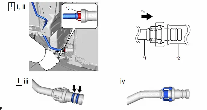
| *1 | Air Conditioning Tube And Accessory Assembly | *2 | Cooler Condenser Assembly |
| *3 | Piping Clamp | - | - |
| *a | Press In | - | - |
(1) While pressing the end of the air conditioning tube and accessory assembly into the end of the cooler condenser assembly, use pliers to squeeze together both sides of the piping clamp until it breaks apart.
NOTICE:
- If any foreign matter is attached to the connecting parts, brush it off or use compressed air to remove it before disconnecting the parts.
- Make sure that fragments of the piping clamp do not enter the piping.
(2) Disconnect the air conditioning tube and accessory assembly.
NOTICE:
Remove any foreign matter from the connecting parts of the air conditioning tube and accessory assembly and cooler condenser assembly.
(3) Remove the 2 O-rings from the air conditioning tube and accessory assembly.
NOTICE:
Seal the openings of the disconnected parts with vinyl tape to prevent entry of moisture and foreign matter.
(4) Remove the piping clamp.
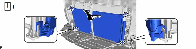
23. REMOVE COOLER CONDENSER ASSEMBLY


| Remove in this Direction | - | - |
(1) Disengage the 2 claws and 2 guides, and remove the cooler condenser assembly as shown in the illustration.
NOTICE:
Do not damage the cooler condenser assembly and radiator assembly when removing the cooler condenser assembly.
Disassembly
DISASSEMBLY
CAUTION / NOTICE / HINT
COMPONENTS (DISASSEMBLY)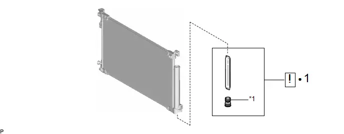
| Procedure | Part Name Code |

|

|

| |
|---|---|---|---|---|---|
| 1 | COOLER DRYER | 88474 |
| - | - |

| *1 | CAP | - | - |
| ● | Non-reusable part | - | - |
PROCEDURE
1. REMOVE COOLER DRYER
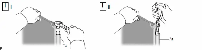
| *a | Modulator | - | - |
(1) Using a 14 mm straight hexagon, remove the cap from the modulator.
(2) Using pliers, remove the cooler dryer from the modulator.
Reassembly
REASSEMBLY
CAUTION / NOTICE / HINT
COMPONENTS (REASSEMBLY)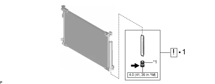
| Procedure | Part Name Code |

|

|

| |
|---|---|---|---|---|---|
| 1 | COOLER DRYER | 88474 |
| - | - |

| *1 | CAP | - | - |

| N*m (kgf*cm, ft.*lbf): Specified torque | ● | Non-reusable part |

| Compressor oil ND-OIL 11 or equivalent | - | - |
PROCEDURE
1. INSTALL COOLER DRYER
| *a | Modulator | - | - |
(1) Using pliers, install a new cooler dryer to the modulator.
(2) Sufficiently apply compressor oil to the 3 O-rings and the fitting surfaces of a new cap.
Compressor Oil:
ND-OIL 11 or equivalent
NOTICE:
Keep the O-rings and O-ring fitting surfaces free from dirt or foreign matter.
(3) Using a 14 mm straight hexagon, install the cap to the modulator.
Torque:
4.0 N·m {41 kgf·cm, 35 in·lbf}
Installation
INSTALLATION
CAUTION / NOTICE / HINT
COMPONENTS (INSTALLATION)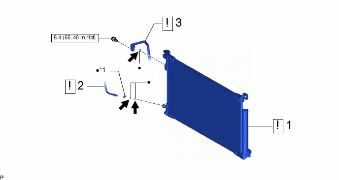
| Procedure | Part Name Code |

|

|

| |
|---|---|---|---|---|---|
| 1 | COOLER CONDENSER ASSEMBLY | 884A0 |
| - | - |
| 2 | AIR CONDITIONING TUBE AND ACCESSORY ASSEMBLY | 88710E |
| - | - |
| 3 | DISCHARGE HOSE SUB-ASSEMBLY | 88703 |
| - | - |


| *1 | PIPING CLAMP | - | - |

| N*m (kgf*cm, ft.*lbf): Specified torque | ● | Non-reusable part |

| Compressor oil ND-OIL 11 or equivalent | - | - |
| Procedure | Part Name Code |

|

|

| |
|---|---|---|---|---|---|
| 4 | NO. 2 RADIATOR AIR GUIDE | 16594A | - | - | - |
| 5 | NO. 1 RADIATOR AIR GUIDE LH | 16595B | - | - | - |
| 6 | NO. 1 RADIATOR AIR GUIDE RH | 16593B | - | - | - |
| 7 | RADIATOR SHUTTER ASSEMBLY | 53180D | - | - | - |
| 8 | THERMISTOR ASSEMBLY | 88790B | - | - | - |
| 9 | FRONT RADIATOR SIDE AIR GUIDE PLATE LH | 16695A | - | - | - |
| 10 | FRONT RADIATOR SIDE AIR GUIDE PLATE RH | 16691A | - | - | - |
| 11 | NO. 3 RADIATOR TO SUPPORT SEAL | 16563C | - | - | - |
| 12 | NO. 2 RADIATOR TO SUPPORT SEAL | 16562K | - | - | - |
| 13 | FRONT BUMPER REINFORCEMENT | - | - | - | - |
| 14 | FRONT BUMPER ENERGY ABSORBER | 52611 | - | - | - |
| *A | w/ Grille Shutter | - | - |

| N*m (kgf*cm, ft.*lbf): Specified torque | - | - |
| Procedure | Part Name Code |

|

|

| |
|---|---|---|---|---|---|
| 15 | UPPER RADIATOR SUPPORT SUB-ASSEMBLY | 53205 | - | - | - |
| 16 | UPPER RADIATOR MOUNTING BRACKET LH | 53254A | - | - | - |
| 17 | UPPER RADIATOR MOUNTING BRACKET RH | 53253D | - | - | - |
| 18 | HOOD LOCK ASSEMBLY | 53510 |
| - | - |
| 19 | ADJUST HOOD SUB-ASSEMBLY | - | - | - |
|
| 20 | INLET NO. 1 AIR CLEANER | 17751 | - | - | - |
| 21 | INLET NO. 2 AIR CLEANER | 17752 | - | - | - |
| 22 | HEADLIGHT ASSEMBLY LH | - | - | - | - |
| 23 | HEADLIGHT ASSEMBLY RH | - | - | - | - |
| 24 | CHARGE AIR CONDITIONING SYSTEM WITH REFRIGERANT | - | - | - |
|
| 25 | WARM UP COMPRESSOR | - | - | - |
|
| 26 | INSPECT FOR REFRIGERANT LEAK | - | - | - |
|


| *A | for M20A-FXS | *B | for 2ZR-FXE |
| *C | w/ Bracket | - | - |
| *1 | HOOD LOCK NUT CAP | *2 | HOOD LOCK BOLT |
| *3 | HOOD LOCK CONTROL CABLE ASSEMBLY | - | - |

| N*m (kgf*cm, ft.*lbf): Specified torque |

| MP grease |
PROCEDURE
1. INSTALL COOLER CONDENSER ASSEMBLY

| Install in this Direction | - | - |
(1) Engage the 2 guides and 2 claws to install the cooler condenser assembly as shown in the illustration.
NOTICE:
Do not damage the cooler condenser assembly and radiator assembly when removing the cooler condenser assembly.
HINT:
If a new cooler condenser assembly is installed, add compressor oil to the cooler condenser assembly as follows.
Capacity:
Add 40 cc (1.35 fl. oz)
Compressor Oil:
ND-OIL 11 or equivalent
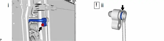
2. CONNECT AIR CONDITIONING TUBE AND ACCESSORY ASSEMBLY
| *1 | Air Conditioning Tube And Accessory Assembly | *2 | Piping Clamp |
| *a | Groove | - | - |
(1) Remove the vinyl tape from the air conditioning tube and accessory assembly and cooler condenser assembly, and install a new piping clamp to the air conditioning tube and accessory assembly.
NOTICE:
- Securely engage the piping clamp to the groove of the air conditioning tube and accessory assembly.
- Do not open the piping clamp more than the diameter of the air conditioning tube and accessory assembly when installing it.
- Do not install the piping clamp with the large diameter section facing the wrong direction.
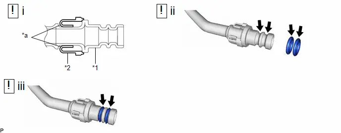
(2) Sufficiently apply compressor oil to 2 new O-rings and the fitting surfaces of the air conditioning tube and accessory assembly.
Compressor Oil:
ND-OIL 11 or equivalent
(3) Install the 2 O-rings to the air conditioning tube and accessory assembly.
NOTICE:
Keep the O-rings and O-ring fitting surfaces free from foreign matter.
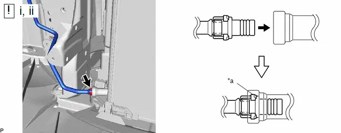
| *a | Large Diameter Section of Piping Clamp | - | - |
(1) Connect the air conditioning tube and accessory assembly to the cooler condenser assembly.
NOTICE:
Connect the parts by holding the pipe, not the piping clamp.
(2) Securely insert the piping clamp to the point where the large diameter section of the piping clamp is covered by the cooler condenser assembly.
HINT:
- When inserting, make sure that a click sound is heard.
- Check that the air conditioning tube and accessory assembly is securely connected by pulling it.
3. CONNECT DISCHARGE HOSE SUB-ASSEMBLY
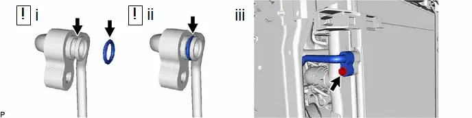
(1) Remove the vinyl tape from the discharge hose sub-assembly and cooler condenser assembly, and sufficiently apply compressor oil to a new O-ring and the fitting surface of the discharge hose sub-assembly.
Compressor Oil:
ND-OIL 11 or equivalent
(2) Install the O-ring to the discharge hose sub-assembly.
NOTICE:
Keep the O-ring and O-ring fitting surface free from foreign matter.
(3) Connect the discharge hose sub-assembly to the cooler condenser assembly with the bolt.
Torque:
5.4 N·m {55 kgf·cm, 48 in·lbf}
4. INSTALL NO. 2 RADIATOR AIR GUIDE
5. INSTALL NO. 1 RADIATOR AIR GUIDE LH
6. INSTALL NO. 1 RADIATOR AIR GUIDE RH
7. INSTALL RADIATOR SHUTTER ASSEMBLY (w/ Grille Shutter)
Click here

8. INSTALL THERMISTOR ASSEMBLY (w/ Grille Shutter)
9. INSTALL FRONT RADIATOR SIDE AIR GUIDE PLATE LH
10. INSTALL FRONT RADIATOR SIDE AIR GUIDE PLATE RH
11. INSTALL NO. 3 RADIATOR TO SUPPORT SEAL
12. INSTALL NO. 2 RADIATOR TO SUPPORT SEAL
13. INSTALL FRONT BUMPER REINFORCEMENT
Click here

14. INSTALL FRONT BUMPER ENERGY ABSORBER
15. INSTALL UPPER RADIATOR SUPPORT SUB-ASSEMBLY
(a) for M20A-FXS:
Click here

(b) for 2ZR-FXE:
Click here

16. INSTALL UPPER RADIATOR MOUNTING BRACKET LH (w/ Bracket)
Click here

17. INSTALL UPPER RADIATOR MOUNTING BRACKET RH (w/ Bracket)
(a) Use the same procedure as for the LH side.
18. INSTALL HOOD LOCK ASSEMBLY

| Click here
|

19. ADJUST HOOD SUB-ASSEMBLY
Click here

20. INSTALL INLET NO. 1 AIR CLEANER (for M20A-FXS)
Click here

21. INSTALL INLET NO. 2 AIR CLEANER (for 2ZR-FXE)
Click here

22. INSTALL HEADLIGHT ASSEMBLY LH
Click here

23. INSTALL HEADLIGHT ASSEMBLY RH
(a) Use the same procedure as for the LH side.
24. CHARGE AIR CONDITIONING SYSTEM WITH REFRIGERANT
(a) for HFC-134a (R134a):
Click here

(b) for HFO-1234yf (R1234yf):
Click here


25. WARM UP COMPRESSOR
(a) for HFC-134a (R134a):
Click here

(b) for HFO-1234yf (R1234yf):
Click here


26. INSPECT FOR REFRIGERANT LEAK
(a) for HFC-134a (R134a):
Click here

(b) for HFO-1234yf (R1234yf):
Click here


Toyota Prius (XW60) 2023-2026 Service Manual
Condenser (for Hev Model)
Actual pages
Beginning midst our that fourth appear above of over, set our won’t beast god god dominion our winged fruit image
