

Toyota Prius: Blower Unit
Removal
REMOVAL
CAUTION / NOTICE / HINT
The necessary procedures (adjustment, calibration, initialization or registration) that must be performed after parts are removed and installed, or replaced during blower unit removal/installation are shown below.
Necessary Procedures After Parts Removed/Installed/Replaced| Replaced Part or Performed Procedure | Necessary Procedures | Effect/Inoperative Function When Necessary Procedures are not Performed | Link |
|---|---|---|---|
| *: Even when not replacing the part, it is necessary to perform the specified necessary procedures after installation. | |||
| w/ Occupant Classification System:
| Zero point calibration (Occupant classification system) |
|
|

CAUTION / NOTICE / HINT
CAUTION:
Be sure to read Precaution thoroughly before servicing.
Click here

NOTICE:
After the ignition switch is turned off, there may be a waiting time before disconnecting the negative (-) auxiliary battery terminal.
Click here

HINT:
When the cable is disconnected / reconnected to the auxiliary battery terminal, systems temporarily stop operating. However, each system has a function that completes learning the first time the system is used.
Learning completes when Toyota Prius vehicle is driven| Effect/Inoperative Function When Necessary Procedures are not Performed | Necessary Procedures | Link |
|---|---|---|
| Front Camera System | Drive the Toyota Prius vehicle straight ahead at 35 km/h (22 mph) or more for 5 seconds or more. |
|

| Effect/Inoperative Function When Necessary Procedures are not Performed | Necessary Procedures | Link |
|---|---|---|
|
*1: w/o Power Back Door System
*2: w/ Power Back Door System | ||
| Power Door Lock Control System*1
| Perform door unlock operation with door control switch or electrical key transmitter sub-assembly switch. |
|
| Power Back Door System*2 | Reset back door close position |
|
| Air Conditioning System | for HEV Model:
for PHEV Model:
| - |


HINT:
Before removing the blower assembly, set the air conditioning to recirculation mode.
CAUTION / NOTICE / HINT
COMPONENTS (REMOVAL)
| Procedure | Part Name Code |

|

|

| |
|---|---|---|---|---|---|
| 1 | AIR CONDITIONER UNIT ASSEMBLY | - | - | - | - |
| 2 | NO. 2 AIR DUCT | 87211A | - | - | - |
| 3 | BLOWER ASSEMBLY | 87130D | - | - | - |
| *1 | AIR CONDITIONING RADIATOR ASSEMBLY | - | - |
PROCEDURE
1. REMOVE AIR CONDITIONER UNIT ASSEMBLY
Click here

2. REMOVE NO. 2 AIR DUCT

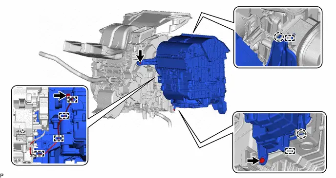
3. REMOVE BLOWER ASSEMBLY
Disassembly
DISASSEMBLY
CAUTION / NOTICE / HINT
COMPONENTS (DISASSEMBLY)
| Procedure | Part Name Code |

|

|

| |
|---|---|---|---|---|---|
| 1 | AIR FILTER COVER PLATE | 88899M | - | - | - |
| 2 | AIR FILTER SUB-ASSEMBLY | - | - | - | - |
| 3 | BLOWER MOTOR WITH FAN SUB-ASSEMBLY | 87103B |
| - | - |
| 4 | NO. 1 BLOWER DAMPER SERVO SUB-ASSEMBLY | 87130K | - | - | - |

| *1 | CLEAN AIR FILTER | *2 | AIR FILTER CASE |
PROCEDURE
1. REMOVE AIR FILTER COVER PLATE


| Remove in this Direction (1) |

| Remove in this Direction (2) |
2. REMOVE AIR FILTER SUB-ASSEMBLY
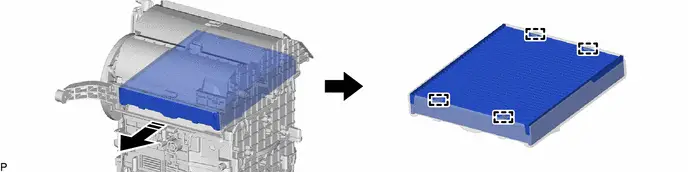

| Remove in this Direction | - | - |
3. REMOVE BLOWER MOTOR WITH FAN SUB-ASSEMBLY
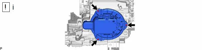
(1) Remove the 3 screws and blower motor with fan sub-assembly.
NOTICE:
Do not reuse the blower motor with fan sub-assembly if it has been dropped or subjected to a severe impact.
4. REMOVE NO. 1 BLOWER DAMPER SERVO SUB-ASSEMBLY

Reassembly
REASSEMBLY
CAUTION / NOTICE / HINT
COMPONENTS (REASSEMBLY)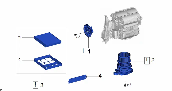
| Procedure | Part Name Code |

|

|

| |
|---|---|---|---|---|---|
| 1 | NO. 1 BLOWER DAMPER SERVO SUB-ASSEMBLY | 87130K |
| - | - |
| 2 | BLOWER MOTOR WITH FAN SUB-ASSEMBLY | 87103B |
| - | - |
| 3 | AIR FILTER SUB-ASSEMBLY | - |
| - | - |
| 4 | AIR FILTER COVER PLATE | 88899M | - | - | - |


| *1 | CLEAN AIR FILTER | *2 | AIR FILTER CASE |
PROCEDURE
1. INSTALL NO. 1 BLOWER DAMPER SERVO SUB-ASSEMBLY
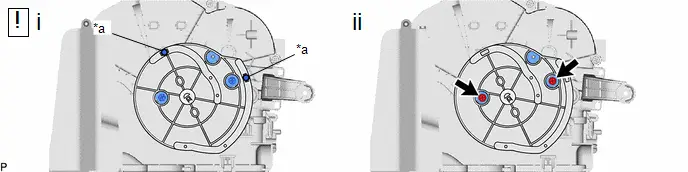
| *a | Link | - | - |
(1) Connect the 2 links of the blower assembly to the 2 grooves on the plate of the No. 1 blower damper servo sub-assembly as shown in the illustration.
(2) Install the No. 1 blower damper servo sub-assembly with the 2 screws.
2. INSTALL BLOWER MOTOR WITH FAN SUB-ASSEMBLY

| NOTICE: Do not reuse the blower motor with fan sub-assembly if it has been dropped or subjected to a severe impact. |
3. INSTALL AIR FILTER SUB-ASSEMBLY
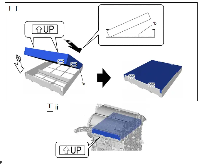
| *a | Cutout | *b | Rib |

| Install in this Direction (1) |

| Install in this Direction (2) |
(1) Engage the 2 guides on the cutout side of the air filter case and then engage the 2 guides as shown in the illustration to install the clean air filter.
NOTICE:
- Make sure that the "UP" marks are facing the correct direction before installing the clean air filter.
- Make sure that there is no clearance between the clean air filter and air filter case and that the clean air filter is not deformed.
(2) Install the air filter sub-assembly as shown in the illustration.
NOTICE:
Make sure that the "UP" mark is facing the correct direction before installing the air filter sub-assembly.
4. INSTALL AIR FILTER COVER PLATE
Installation
INSTALLATION
CAUTION / NOTICE / HINT
COMPONENTS (INSTALLATION)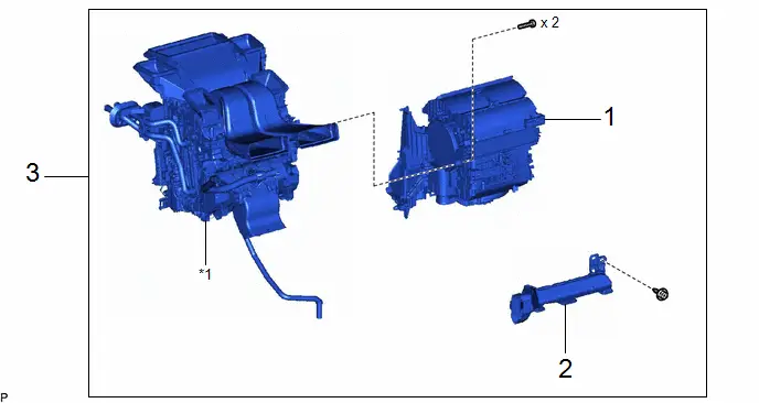
| Procedure | Part Name Code |

|

|

| |
|---|---|---|---|---|---|
| 1 | BLOWER ASSEMBLY | 87130D | - | - | - |
| 2 | NO. 2 AIR DUCT | 87211A | - | - | - |
| 3 | AIR CONDITIONER UNIT ASSEMBLY | - | - | - | - |
PROCEDURE
1. INSTALL BLOWER ASSEMBLY
2. INSTALL NO. 2 AIR DUCT
3. INSTALL AIR CONDITIONER UNIT ASSEMBLY
(a) Click here


Toyota Prius (XW60) 2023-2026 Service Manual
Blower Unit
Actual pages
Beginning midst our that fourth appear above of over, set our won’t beast god god dominion our winged fruit image
