

Toyota Prius: Charge Lid Opener System
- Precaution
- Parts Location
- System Diagram
- How To Proceed With Troubleshooting
- Problem Symptoms Table
- Data List / Active Test
- Multi-information Display Indicates Open when Charge Lid is Closed
Precaution
PRECAUTION
PRECAUTIONS FOR DISCONNECTING CABLE FROM NEGATIVE (-) AUXILIARY BATTERY TERMINAL
NOTICE:
After the ignition switch is turned off, there may be a waiting time before disconnecting the negative (-) auxiliary battery terminal.
Click here

HINT:
When disconnecting and reconnecting the auxiliary battery, there is an automatic learning function that completes learning when the respective system is used.
Click here

PRECAUTIONS FOR INSPECTING CHARGE LID OPENER SYSTEM
(a) Refer to the precaution of plug-in charge control system when inspecting the charge lid opener system.
Click here

Parts Location
PARTS LOCATION
ILLUSTRATION
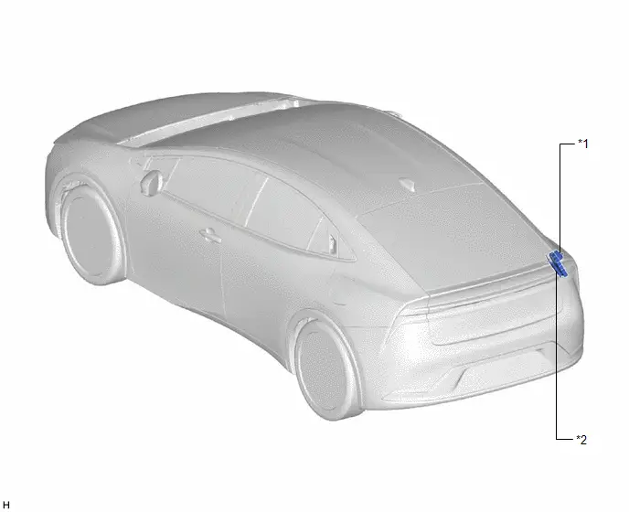
| *1 | CHARGE LID WITH MOTOR LOCK ASSEMBLY - COURTESY SWITCH | *2 | PLUGIN CHARGE CONTROL ECU ASSEMBLY |
ILLUSTRATION
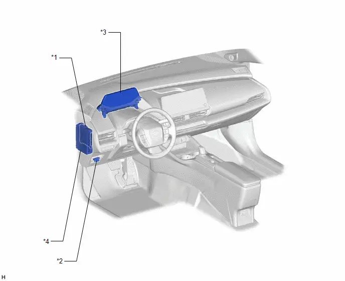
| *1 | MAIN BODY ECU (MULTIPLEX NETWORK BODY ECU) | *2 | DLC3 |
| *3 | COMBINATION METER ASSEMBLY | *4 | POWER DISTRIBUTION BOX ASSEMBLY - ECU-B NO.3 FUSE |
System Diagram
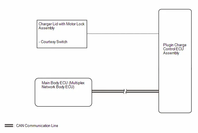
SYSTEM DIAGRAM
How To Proceed With Troubleshooting
CAUTION / NOTICE / HINT
HINT:
- Use the following procedure to troubleshoot the charge lid opener system.
- *: Use the GTS.
PROCEDURE
| 1. | Toyota Prius Vehicle BROUGHT TO WORKSHOP |
|

| 2. | CUSTOMER PROBLEM ANALYSIS |
HINT:
- In troubleshooting, confirm that the problem symptoms have been accurately identified. Preconceptions should be discarded in order to make an accurate judgment. To clearly understand what the problem symptoms are, it is extremely important to ask the customer about the problem and the conditions at the time the malfunction occurred.
- Gather as much information as possible for reference. Past problems that seem unrelated may also help in some cases.
-
The following 5 items are important points for problem analysis:
What
Toyota Prius Vehicle model, system name
When
Date, time, occurrence frequency
Where
Road conditions
Under what conditions?
Driving conditions, weather conditions
How did it happen?
Problem symptoms
|

| 3. | PRE-CHECK |
(a) Measure the auxiliary battery voltage with the ignition switch off.
Standard voltage:
11 to 14 V
If the voltage is below 11 V, recharge or replace the auxiliary battery before proceeding to the next step.
(b) Check the fuses and relays.
(c) Check the connector connections and terminals to make sure that there are no abnormalities such as loose connections, deformation, etc.
|

| 4. | CHECK COMMUNICATION FUNCTION OF CAN COMMUNICATION SYSTEM* |
(a) Using the GTS, check for CAN communication system DTCs.
Click here

| Result | Proceed to |
|---|---|
| CAN DTCs are not output | A |
| CAN DTCs are output | B |
| B |

| GO TO CAN COMMUNICATION SYSTEM |
|

| 5. | PROBLEM SYMPTOMS TABLE |
(a) Refer to Problem Symptoms Table.
Click here

| Result | Proceed to |
|---|---|
| Fault is not listed in Problem Symptoms Table | A |
| Fault is listed in Problem Symptoms Table | B |
| B |

| GO TO STEP 7 |
|

| 6. | OVERALL ANALYSIS AND TROUBLESHOOTING* |
(a) Data List / Active Test
Click here

(b) Inspection
|

| 7. | REPAIR OR REPLACE |
|

| 8. | CONFIRMATION TEST |
| NEXT |

| END |
Problem Symptoms Table
PROBLEM SYMPTOMS TABLE
HINT:
- Use the table below to help determine the cause of problem symptoms. If multiple suspected areas are listed, the potential causes of the symptoms are listed in order of probability in the "Suspected Area" column of the table. Check each symptom by checking the suspected areas in the order they are listed. Replace parts as necessary.
- Inspect the fuses and relays related to this system before inspecting the suspected areas below.
| Symptom | Suspected Area | Link |
|---|---|---|
| Multi-information display indicates open when charge lid is closed | Proceed to "Multi-information Display Indicates Open when Charge Lid is Closed" |
|

Data List / Active Test
DATA LIST / ACTIVE TEST
NOTICE:
In the table below, the values listed under "Normal Condition" are reference values. Do not depend solely on these reference values when deciding whether a part is faulty or not.
HINT:
Using the GTS to read the Data List allows the values or states of switches, sensors, actuators and other items to be read without removing any parts. This non-intrusive inspection can be very useful because intermittent conditions or signals may be discovered before parts or wiring is disturbed. Reading the Data List information early in troubleshooting is one way to save diagnostic time.
DATA LIST
(a) Read the Data List according to the display on the GTS.
Powertrain > Plug-in Control > Data List| Tester Display | Measurement Item | Range | Normal Condition | Diagnostic Note |
|---|---|---|---|---|
| Charging Lid Switch Status | Charging lid switch status | OFF/ON | OFF: Charging port lid close (push lifter of charger lid with motor lock assembly pushed in) ON: Charging port lid open (push lifter of charger lid with motor lock assembly extended) | (LDSW terminal) |
| Charging Connector Connect Status Voltage | PISW terminal voltage used for checking electric Toyota Prius vehicle charger cable assembly connection condition | 0.00 to 79.99 V | 0.35 to 2.02 V: Electric vehicle charger cable assembly inserted 2.02 to 3.57 V: Electric vehicle charger cable assembly inserted and the latch release button (PI switch) engaged 3.57 to 4.73 V: Electric Toyota Prius vehicle charger cable assembly not inserted | (PISW terminal) |
| Charging Connector Lock Pin Status | Charging connector lock pin status | Unlock/Lock | Unlock: Charging connector lock pin not extended Lock: Charging connector lock pin extended | (CBSW terminal) |
| Charging Connector Lock Motor Unlock Direction Revolution Request Current | Output of current to operate charging connector lock motor or charging port lid lock motor in reverse* | OFF/ON | OFF: Charging connector lock motor or charging port lid lock motor not operated ON: Unlocking charging connector or charging port lid (operating charging connector lock motor or charging port lid lock motor in reverse) | (CBMN terminal) |
| Charging Connector Lock Motor Lock Direction Revolution Request Current | Output of current to operate charging connector lock motor or charging port lid lock motor forward* | OFF/ON | OFF: Charging connector lock motor or charging port lid lock motor not operated ON: Unlocking charging connector or charging port lid (operating charging connector lock motor or charging port lid lock motor forward) | (CBMP terminal) |
- *: Cannot be used
Multi-information Display Indicates Open when Charge Lid is Closed
DESCRIPTION
The plugin charge control ECU assembly detects and sends the charger lid with motor lock assembly (courtesy switch) on/off signal to the combination meter assembly via CAN communication, and the charge lid open/close information is displayed on the multi-information display.
When the charge lid open/close information is not correctly displayed on the multi-information display, the charger lid with motor lock assembly (courtesy switch) may be improperly installed, the wire harness between the charger lid with motor lock assembly (courtesy switch) and plugin charge control ECU assembly may be malfunctioning, or there may be an internal malfunction in the plugin charge control ECU assembly.
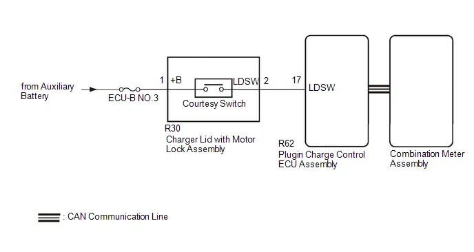
WIRING DIAGRAM
CAUTION / NOTICE / HINT
CAUTION:
Refer to the precautions before inspecting high voltage circuit.
Click here

NOTICE:
-
After turning the power switch off, waiting time may be required before disconnecting the cable from the negative (-) auxiliary battery terminal. Therefore, make sure to read the disconnecting the cable from the negative (-) auxiliary battery terminal notices before proceeding with work.
Click here

-
The charge lid opener system uses the CAN communication system. Inspect the communication function by following How to Proceed with Troubleshooting. Troubleshoot the charge lid opener system after confirming that the communication system is functioning properly.
Click here

- Check that there are no electrical key transmitter sub-assemblies in the Toyota Prius vehicle.
- Inspect the fuses for circuits related to this system before performing the following procedure.
- To protect the charging port lid lock motor, if the charging port lid lock/unlock is operated repeatedly, operation of the unlock will be prohibited. Wait for 3 minutes or more to allow the motor to cool and then resume the inspection.
- To protect the charging port lid lock motor, if the charging port lid lock/unlock is operated repeatedly in quick succession, operation of the unlock will be prohibited for a certain amount of time. Wait for 3 seconds or more after operation was prohibited and then resume the inspection.
- If the charging port lid lock pin or lid lifter is dirty or frozen, or if foreign matter is caught between the charging port lid lock pin and charging port lid, the charging port lid lock pin may not be able to be locked/unlocked. Clean the charging port lid lock pin before performing the inspection.
-
The charging port lid lock may not operate if the charge inlet box assembly has damaged. Thus, check the charge inlet box assembly first.
Click here

PROCEDURE
| 1. | CHECK FOR DTC |
(a) Check for DTCs.
Powertrain > Plug-in Control > Trouble CodesOK:
DTC is not output
| NG |

| GO TO PLUG-IN CHARGE CONTROL SYSTEM |
|

| 2. | READ VALUE USING GTS (CHARGING LID SWITCH STATUS) |
(a) Read the Data List according to the display on the GTS.
Powertrain > Plug-in Control| Tester Display | Measurement Item | Range | Normal Condition | Diagnostic Note |
|---|---|---|---|---|
| Charging Lid Switch Status | Charging lid switch status | OFF/ON | OFF: Charging port lid close (push lifter of charger lid with motor lock assembly pushed in) ON: Charging port lid open (push lifter of charger lid with motor lock assembly extended) | - |
| Tester Display |
|---|
| Charging Lid Switch Status |
OK:
The GTS display changes correctly in response to the charger lid with motor lock assembly (courtesy switch) operation.
| OK |

| REPLACE COMBINATION METER ASSEMBLY |
|

| 3. | CHECK THE INSTALLATION CONDITION OF CHARGE LID WITH MOTOR LOCK ASSEMBLY (COURTESY SWITCH) |
(a) Install charger lid with motor lock assembly (courtesy switch) properly.
Click here

|

| 4. | INSPECT CHARGE LID WITH MOTOR LOCK ASSEMBLY (COURTESY SWITCH) |
(a) Unlock the any doors.
(b) Push the charge lid to open/close it.
(c) Close the charge lid.
(d) Check that charge lid open message is not displayed on the multi-information display.
OK:
Charge lid open message is not displayed.
| OK |

| END (PROBLEM DUE TO THE INSTALLATION CONDITION OF CHARGE LID WITH MOTOR LOCK ASSEMBLY (COURTESY SWITCH)) |
|

| 5. | INSPECT CHARGE LID WITH MOTOR LOCK ASSEMBLY |
Click here

| NG |

| REPLACE CHARGE LID WITH MOTOR LOCK ASSEMBLY |
|

| 6. | CHECK HARNESS AND CONNECTOR (CHARGE LID WITH MOTOR LOCK ASSEMBLY (COURTESY SWITCH) - PLUGIN CHARGE CONTROL ECU ASSEMBLY (LDSW TERMINAL)) |
CAUTION:
Be sure to wear insulated gloves.
(a) Disconnect the R30 charger lid with motor lock assembly connector.
(b) Disconnect the R62 plugin charge control ECU assembly connector.
(c) Measure the resistance according to the value(s) in the table below.
Standard Resistance:
 Click Location & Routing(R30,R62) Click Connector(R30) Click Connector(R62)
 | Tester Connection | Condition | Specified Condition |
|---|---|---|
| R30-2 (LDSW) - R62-17 (LDSW) | Always | Below 1 Ω |
| R30-2 (LDSW) or R62-17 (LDSW) - Body ground | Always | 10 kΩ or higher |
| OK |

| REPLACE PLUGIN CHARGE CONTROL ECU ASSEMBLY |
| NG |

| REPAIR OR REPLACE HARNESS OR CONNECTOR |

Toyota Prius (XW60) 2023-2026 Service Manual
Charge Lid Opener System
- Precaution
- Parts Location
- System Diagram
- How To Proceed With Troubleshooting
- Problem Symptoms Table
- Data List / Active Test
- Multi-information Display Indicates Open when Charge Lid is Closed
Actual pages
Beginning midst our that fourth appear above of over, set our won’t beast god god dominion our winged fruit image
