

Toyota Prius: Charge Lid Opener Motor Assembly
Removal
REMOVAL
CAUTION / NOTICE / HINT
The necessary procedures (adjustment, calibration, initialization or registration) that must be performed after parts are removed and installed, or replaced during battery charger connector opening lid sub-assembly removal/installation are shown below.
CAUTION:
-
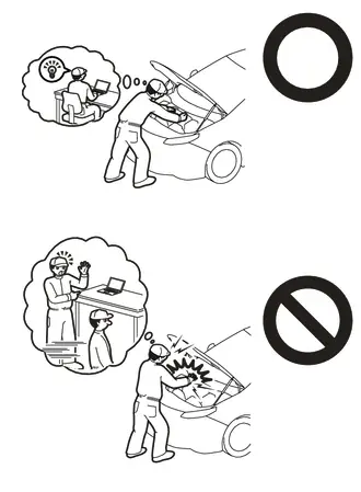
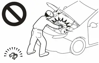
Orange wire harnesses and connectors indicate high-voltage circuits. To prevent electric shock, always follow the procedure described in the repair manual.
Click here

-
To prevent electric shock, wear insulated gloves when working on wire harnesses and components of the high voltage system.
NOTICE:
- After the ignition switch is turned off, the radio and display receiver assembly recordsvarious types of memory and settings. As a result, after turning the ignition switch off,make sure to wait at least 3 minutes before disconnecting the cable from the negative(-) auxiliary battery terminal.
- When the cable is disconnected from the negative (-) auxiliary battery terminal and thesecurity lock setting has been enabled, multi-display operations will be disabled uponnext startup unless the password is entered. Be sure to check the security lock settingbefore disconnecting the cable from the negative (-) auxiliary battery terminal.
CAUTION / NOTICE / HINT
HINT:
-
When the cable is disconnected / reconnected to the auxiliary battery terminal, systems temporarily stop operating. However, each system has a function that completes learning the first time the system is used.
-
Learning completes when Toyota Prius vehicle is driven
Effect/Inoperative Function When Necessary Procedures are not Performed
Necessary Procedures
Link
Front Camera System
Drive the Toyota Prius vehicle straight ahead at 35 km/h (22 mph) or more for 5 seconds or more.

-
Learning completes when vehicle is operated normally
Effect/Inoperative Function When Necessary Procedures are not Performed
Necessary Procedures
Link
*1: w/o Power Back Door System *2: w/ Power Back Door System
Power Door Lock Control System*1
- Back door opener
Perform door unlock operation with door control switch or electrical key transmitter sub-assembly switch.

Power Back Door System*2
Reset back door close position

Air Conditioning System
After the ignition switch is turned to ON, the servo motor and expansion valve standard position is recognized.
-
-
Learning completes when Toyota Prius vehicle is driven
- Use the same procedure for the RH side and LH side.
- The following procedure is for the LH side.
CAUTION / NOTICE / HINT
COMPONENTS (REMOVAL)
| Procedure | Part Name Code |

|

|

| |
|---|---|---|---|---|---|
| 1 | BATTERY CHARGER CONNECTOR OPENING LID SUB-ASSEMBLY | 58409E | - | - | - |
| 2 | CHARGE LID LOCK WITH MOTOR ASSEMBLY | 77030B | - | - | - |
PROCEDURE
1. REMOVE BATTERY CHARGER CONNECTOR OPENING LID SUB-ASSEMBLY
Click here

2. REMOVE CHARGE LID LOCK WITH MOTOR ASSEMBLY

Inspection
INSPECTION
PROCEDURE
1. CHARGE LID LOCK WITH MOTOR ASSEMBLY
(a) Check the operation of the charge lid lock with motor assembly (motor operation).
| (1) Apply auxiliary battery voltage to the charge lid lock with motor assembly connector, and check the operation of the charge lid lock with motor assembly. OK:  Click Location & Routing(R30) Click Connector(R30) Click Location & Routing(R30) Click Connector(R30)
|
|
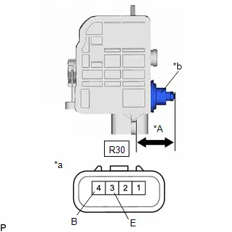
(2) If the result is not as specified, replace the charge lid lock with motor assembly.
(b) Measure the shaft stroke.
OK:
| Area | Condition | Specified Condition |
|---|---|---|
| *A | Lever pulled | 23.2 to 39.5 mm (0.913 to 1.56 in.) |
(1) If the result is not as specified, replace the charge lid lock with motor assembly.
Installation
INSTALLATION
CAUTION / NOTICE / HINT
COMPONENTS (INSTALLATION)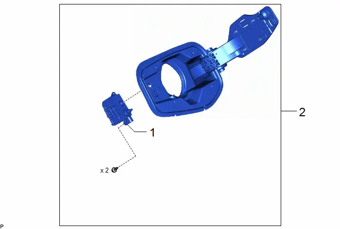
| Procedure | Part Name Code |

|

|

| |
|---|---|---|---|---|---|
| 1 | CHARGE LID LOCK WITH MOTOR ASSEMBLY | 77030B | - | - | - |
| 2 | BATTERY CHARGER CONNECTOR OPENING LID SUB-ASSEMBLY | 58409E | - | - | - |
PROCEDURE
1. INSTALL CHARGE LID LOCK WITH MOTOR ASSEMBLY
2. INSTALL BATTERY CHARGER CONNECTOR OPENING LID SUB-ASSEMBLY
Click here


Toyota Prius (XW60) 2023-2026 Service Manual
Charge Lid Opener Motor Assembly
Actual pages
Beginning midst our that fourth appear above of over, set our won’t beast god god dominion our winged fruit image
