

Toyota Prius: Center Airbag Sensor Assembly
Removal
REMOVAL
CAUTION / NOTICE / HINT
The necessary procedures (adjustment, calibration, initialization or registration) that must be performed after parts are removed and installed, or replaced during airbag ECU assembly removal/installation are shown below.
Necessary Procedures After Parts Removed/Installed/Replaced| Replaced Part or Performed Procedure | Necessary Procedure | Effect/Inoperative Function when Necessary Procedure not Performed | Link |
|---|---|---|---|
| *: Even when not replacing the part, it is necessary to perform the specified necessary procedures after installation. | |||
| Airbag ECU assembly | ECU configuration | Toyota Prius Vehicle Control History (RoB) are stored |
|
| Update ECU security key | Vehicle Control History (RoB) are stored |
| |
| Write the VIN/Toyota Prius Vehicle Identification Number | - |
| |
| Switch the specification information | - |
| |
| Perform "Calibration"* |
|
| |
| w/ Occupant Classification System:
|
|
| |


CAUTION / NOTICE / HINT
HINT:
When the cable is disconnected / reconnected to the auxiliary battery terminal, systems temporarily stop operating. However, each system has a function that completes learning the first time the system is used.
Learning completes when Toyota Prius vehicle is driven| Effect/Inoperative Function when Necessary Procedure not Performed | Necessary Procedure | Link |
|---|---|---|
| Front Camera System | Drive the Toyota Prius vehicle straight ahead at 35 km/h (22 mph) or more for 5 seconds or more. |
|

| Effect/Inoperative Function when Necessary Procedure not Performed | Necessary Procedure | Link |
|---|---|---|
|
*1: w/o Power Back Door System
*2: w/ Power Back Door System | ||
| Power Door Lock Control System*1
| Perform door unlock operation with door control switch or electrical key transmitter sub-assembly switch. |
|
| Power Back Door System*2 | Reset back door close position |
|
| Air Conditioning System | for HEV Model:
for PHEV Model:
| - |


CAUTION / NOTICE / HINT
COMPONENTS (REMOVAL)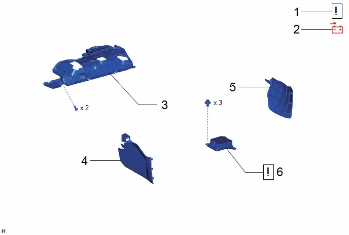
| Procedure | Part Name Code |

|

|

| |
|---|---|---|---|---|---|
| 1 | PRECAUTION | - |
| - | - |
| 2 | DISCONNECT CABLE FROM NEGATIVE AUXILIARY BATTERY TERMINAL | - |
| - | - |
| 3 | NO. 1 INSTRUMENT PANEL UNDER COVER SUB-ASSEMBLY | 55606 | - | - | - |
| 4 | FRONT NO. 1 CONSOLE BOX INSERT | 58816D | - | - | - |
| 5 | FRONT NO. 2 CONSOLE BOX INSERT | 58817A | - | - | - |
| 6 | AIRBAG ECU ASSEMBLY | 89170A |
| - | - |


PROCEDURE
1. PRECAUTION

| CAUTION: Be sure to read Precaution thoroughly before servicing. 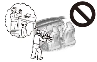 Click here
NOTICE: After the ignition switch is turned off, there may be a waiting time before disconnecting the negative (-) auxiliary battery terminal. Click here
|


2. DISCONNECT CABLE FROM NEGATIVE AUXILIARY BATTERY TERMINAL

| CAUTION: Wait at least 60 seconds after disconnecting the cable from the negative (-) auxiliary battery terminal to disable the SRS system. 
|
-
for M20A-FXS:
Click here

-
for 2ZR-FXE:
Click here

3. REMOVE NO. 1 INSTRUMENT PANEL UNDER COVER SUB-ASSEMBLY
Click here

4. REMOVE FRONT NO. 1 CONSOLE BOX INSERT
Click here

5. REMOVE FRONT NO. 2 CONSOLE BOX INSERT
Click here

6. REMOVE AIRBAG ECU ASSEMBLY
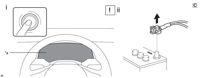
| *a | Illumination off | - | - |
(1) Check that the ignition switch is off.
(2) Check that the cable is disconnected from the negative (-) auxiliary battery terminal.
CAUTION:
Wait at least 60 seconds after disconnecting the cable from the negative (-) auxiliary battery terminal to disable the SRS system.
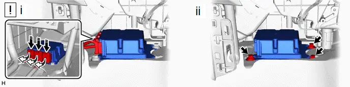

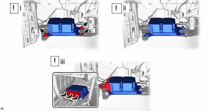
| Release the lock |

| Disconnect the connector |
(1) Release the lock, and then disconnect the connectors.
NOTICE:
When disconnecting any airbag connector, take care not to damage the airbag wire harness.
(2) Remove the 3 bolts and airbag ECU assembly.
Installation
INSTALLATION
CAUTION / NOTICE / HINT
NOTICE:
- After replacing the airbag ECU assembly, make sure to perform ECU Configuration, Update ECU Security Key, Write VIN/Vehicle Identification Number, and Switching Specification Information.
- After performing the ECU configuration procedure and update ECU security key procedure, make sure to perform the initialization procedure for when the cable has been disconnected and reconnected to the negative (-) auxiliary battery terminal.
CAUTION / NOTICE / HINT
COMPONENTS (INSTALLATION)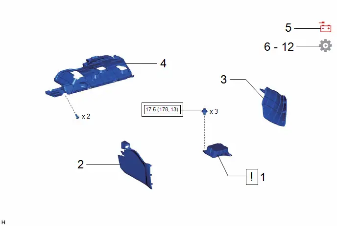
| Procedure | Part Name Code |

|

|

| |
|---|---|---|---|---|---|
| 1 | AIRBAG ECU ASSEMBLY | 89170A |
| - | - |
| 2 | FRONT NO. 1 CONSOLE BOX INSERT | 58816D | - | - | - |
| 3 | FRONT NO. 2 CONSOLE BOX INSERT | 58817A | - | - | - |
| 4 | NO. 1 INSTRUMENT PANEL UNDER COVER SUB-ASSEMBLY | 55606 | - | - | - |
| 5 | CONNECT CABLE TO NEGATIVE AUXILIARY BATTERY TERMINAL | - |
| - | - |
| 6 | ECU CONFIGURATION | - | - | - |
|
| 7 | UPDATE ECU SECURITY KEY | - | - | - |
|
| 8 | WRITE VIN/Toyota Prius Vehicle IDENTIFICATION NUMBER | - | - | - |
|
| 9 | SWITCHING SPECIFICATION INFORMATION | - | - | - |
|
| 10 | INSPECT SRS WARNING LIGHT | - | - | - |
|
| 11 | INITIALIZATION AFTER RECONNECTING AUXILIARY BATTERY TERMINAL | - | - | - |
|
| 12 | PERFORM INITIALIZATION | - | - | - |
|


| Tightening torque for "Major areas involving basic Toyota Prius vehicle performance such as moving/turning/stopping": N*m (kgf*cm, ft.*lbf) | - | - |
| Procedure | Part Name Code |

|

|

| |
|---|---|---|---|---|---|
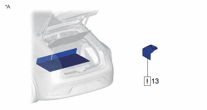
| 13 | BATTERY SERVICE HOLE COVER ASSEMBLY | 58440 |
| - | - |

| *A | for M20A-FXS | - | - |
PROCEDURE
1. INSTALL AIRBAG ECU ASSEMBLY

| *a | Illumination off | - | - |
(1) Check that the ignition switch is off.
(2) Check that the cable is disconnected from the negative (-) auxiliary battery terminal.
CAUTION:
Wait at least 60 seconds after disconnecting the cable from the negative (-) auxiliary battery terminal to disable the SRS system.

| Move in this Direction | - | - |
(1) Install the airbag ECU assembly with the 3 bolts.
Torque:
17.5 N·m {178 kgf·cm, 13 ft·lbf}
NOTICE:
- Temporarily tighten the bolt (A) and then fully tighten the 3 bolts in the order of (B), (C) and (A).
- If the airbag ECU assembly has been dropped, or there are any cracks, dents or other defects in the case or connector, replace it with a new one.
- When installing the airbag ECU assembly, make sure that the wire harness does not interfere with other parts and is not pinched.
- When the ignition switch is first turned to ON after the airbag ECU assembly has been replaced, make sure that no one is in the Toyota Prius vehicle.
(2) Check that there is no looseness in the installed parts of the airbag ECU assembly.
(3) Temporarily connect the connectors and then move the lock lever in the direction indicated by the arrow to securely connect the connectors.
NOTICE:
When connecting any airbag connector, take care not to damage the airbag wire harness.
2. INSTALL FRONT NO. 1 CONSOLE BOX INSERT
3. INSTALL FRONT NO. 2 CONSOLE BOX INSERT
4. INSTALL NO. 1 INSTRUMENT PANEL UNDER COVER SUB-ASSEMBLY
5. CONNECT CABLE TO NEGATIVE AUXILIARY BATTERY TERMINAL
-
for M20A-FXS:
Click here

-
for 2ZR-FXE:
Click here

6. ECU CONFIGURATION
Click here

7. UPDATE ECU SECURITY KEY
Click here

8. WRITE VIN/Toyota Prius Vehicle IDENTIFICATION NUMBER
Click here

9. SWITCHING SPECIFICATION INFORMATION
Click here

10. INSPECT SRS WARNING LIGHT
Click here

11. INITIALIZATION AFTER RECONNECTING AUXILIARY BATTERY TERMINAL
HINT:
When disconnecting and reconnecting the auxiliary battery, there is an automatic learning function that completes learning when the respective system is used.
Click here


12. PERFORM INITIALIZATION
for Electronically Controlled Brake System: Click here

for Occupant Classification System: Click here

13. INSTALL BATTERY SERVICE HOLE COVER ASSEMBLY (for M20A-FXS)

| Click here
|


Toyota Prius (XW60) 2023-2026 Service Manual
Center Airbag Sensor Assembly
Actual pages
Beginning midst our that fourth appear above of over, set our won’t beast god god dominion our winged fruit image
